JP2007178018A - Heat exchanger - Google Patents
Heat exchanger Download PDFInfo
- Publication number
- JP2007178018A JP2007178018A JP2005374269A JP2005374269A JP2007178018A JP 2007178018 A JP2007178018 A JP 2007178018A JP 2005374269 A JP2005374269 A JP 2005374269A JP 2005374269 A JP2005374269 A JP 2005374269A JP 2007178018 A JP2007178018 A JP 2007178018A
- Authority
- JP
- Japan
- Prior art keywords
- header
- header tank
- plate
- refrigerant
- intermediate plate
- Prior art date
- Legal status (The legal status is an assumption and is not a legal conclusion. Google has not performed a legal analysis and makes no representation as to the accuracy of the status listed.)
- Granted
Links
Images


Abstract
Description
この発明は、熱交換器に関し、さらに詳しくは、たとえばCO2(二酸化炭素)などの超臨界冷媒が用いられる超臨界冷凍サイクルのガスクーラとして好適に使用される熱交換器に関する。 The present invention relates to a heat exchanger, and more particularly to a heat exchanger suitably used as a gas cooler of a supercritical refrigeration cycle in which a supercritical refrigerant such as CO 2 (carbon dioxide) is used.
この明細書および特許請求の範囲において、「超臨界冷凍サイクル」とは、高圧側において、冷媒が臨界圧力を超えた超臨界状態となる冷凍サイクルを意味するものとし、「超臨界冷媒」とは、超臨界冷凍サイクルに用いられる冷媒を意味するものとする。 In this specification and claims, the term “supercritical refrigeration cycle” means a refrigeration cycle in which the refrigerant is in a supercritical state exceeding the critical pressure on the high pressure side, and “supercritical refrigerant” It shall mean a refrigerant used in a supercritical refrigeration cycle.
一般に車両用や屋内用の空気調和装置の冷凍サイクルの冷媒としては、ハイドロクロロフルオロカーボンやハイドロフルオロカーボンなどのフロン系のものが広く使用されているが、フロン系冷媒は、オゾン破壊物質、地球温暖化物質であることから、大気中への排出が厳しく制限されており、フロン系冷媒の代替物質の開発、いわゆる脱フロン化の技術開発が進められている。 Generally, chlorofluorocarbons and hydrofluorocarbons such as hydrochlorofluorocarbons are widely used as refrigeration cycle refrigerants for vehicles and indoor air conditioners. Since it is a substance, its emission to the atmosphere is severely restricted, and the development of alternative substances for chlorofluorocarbon refrigerants, so-called de-fluorocarbon technology development, is underway.
脱フロン対策の1つとして、たとえばCO2(二酸化炭素)を冷媒として用いる超臨界冷凍サイクルが提案されている。CO2は自然界に存在する自然冷媒の1つで、フロン系冷媒に比べ地球温暖化に対する影響を示す地球温暖化係数がはるかに低く、地球環境にほとんど影響を及ぼさない。 As one of countermeasures against chlorofluorocarbons, a supercritical refrigeration cycle using, for example, CO 2 (carbon dioxide) as a refrigerant has been proposed. CO 2 is one of natural refrigerants existing in the natural world, and has a much lower global warming coefficient that shows an effect on global warming than a chlorofluorocarbon refrigerant, and hardly affects the global environment.
ところで、CO2を蒸気圧縮式冷凍サイクルの冷媒に使用した場合、CO2固有の熱力学的性質により凝縮課程を伴わない遷臨界サイクルとなり、高圧側の熱交換器内で凝縮が発生しないため、高圧側熱交換器はガスクーラと呼ばれており、圧縮機、ガスクーラ、エバポレータ、減圧器、ガスクーラから出てきた冷媒とエバポレータから出てきた冷媒とを熱交換させる中間熱交換器、およびアキュムレータによって超臨界冷凍サイクルが構成されるようになっている。 By the way, when CO 2 is used as a refrigerant for a vapor compression refrigeration cycle, it becomes a transcritical cycle without a condensation process due to the thermodynamic properties inherent to CO 2 , and condensation does not occur in the high-pressure side heat exchanger. The high-pressure side heat exchanger is called a gas cooler. A critical refrigeration cycle is configured.
超臨界冷凍サイクルのガスクーラに用いられる熱交換器として、互いに間隔をおいて配置された上下方向に伸びる1対のヘッダタンクと、両ヘッダタンク間に上下方向に間隔をおいて配置され、かつ両端部が両ヘッダタンクに接続された複数の扁平状熱交換管とを備えており、第1のヘッダタンクに、入口ヘッダ部と出口ヘッダ部とが上下に並んで設けられ、第2のヘッダタンクに、第1ヘッダタンクの隣り合う2つのヘッダ部に跨るように1つの中間ヘッダ部が設けられ、第1ヘッダタンクの入口ヘッダ部の上端部に冷媒入口が設けられるとともに、出口ヘッダ部の下端部に冷媒出口が設けられ、第2ヘッダタンクの中間ヘッダ部の上半部は、熱交換管を通って入口ヘッダ部から冷媒が流入する流入部となっており、すべての熱交換管が、上下に連続して並んだ複数の熱交換管からなる上下2つのパスに区分され、上側パスの熱交換管が入口ヘッダ部および中間ヘッダ部の流入部に接続され、下側パスの熱交換管が出口ヘッダ部および中間ヘッダ部の下半部に接続されている熱交換器が知られている(特許文献1参照)。 As a heat exchanger used in a gas cooler of a supercritical refrigeration cycle, a pair of header tanks extending vertically and spaced apart from each other, and vertically spaced between both header tanks, and both ends A plurality of flat heat exchange pipes connected to both header tanks, the first header tank is provided with an inlet header portion and an outlet header portion arranged vertically, and a second header tank In addition, one intermediate header portion is provided so as to straddle two adjacent header portions of the first header tank, a refrigerant inlet is provided at an upper end portion of the inlet header portion of the first header tank, and a lower end of the outlet header portion. The refrigerant outlet is provided in the part, the upper half of the intermediate header part of the second header tank is an inflow part through which the refrigerant flows from the inlet header part through the heat exchange pipe, and all the heat exchange pipes are It is divided into two upper and lower paths consisting of a plurality of heat exchange pipes arranged continuously below, and the heat exchange pipe of the upper path is connected to the inlet header part and the inflow part of the intermediate header part, and the heat exchange pipe of the lower path Is known that is connected to the lower half of the outlet header and the intermediate header (see Patent Document 1).
ところで、超臨界冷凍サイクルの圧縮機においては、通常、摺動部の潤滑のために潤滑油が使用されており、そのため超臨界冷媒中に( )〜( )質量%程度の潤滑油が必然的に混入しているが、ガスクーラの中には液相は存在しないので、冷媒と潤滑油とが分離してガスクーラ内を流動している。 By the way, in a compressor of a supercritical refrigeration cycle, a lubricating oil is usually used for lubrication of a sliding portion. Therefore, a lubricating oil of about () to () mass% is inevitable in the supercritical refrigerant. However, since there is no liquid phase in the gas cooler, the refrigerant and the lubricating oil are separated and flow in the gas cooler.
そして、特許文献1記載の熱交換器においては、上側パスの下端部側の熱交換管、すなわち冷媒入口からの距離が遠い熱交換管内に潤滑油が滞留して冷媒が流れにくくなり、放熱性能が低下するという問題がある。
In the heat exchanger described in
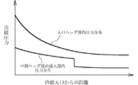
上記問題が発生する原因は、第1ヘッダタンクの入口ヘッダ部内の圧力分布と、第2ヘッダタンクの中間ヘッダ部内の圧力分布にある。すなわち、入口ヘッダ部内の圧力分布と、中間ヘッダ部の流入部内の圧力分布とは、図12に示すようになり、入口ヘッダ部内の圧力と中間ヘッダ部の流入部内の圧力との差圧は、冷媒入口に近い部分で大きく、冷媒入口からの距離が大きくなるにしたがって小さくなる。したがって、上側パスの下端部側の熱交換管内の冷媒流量が少なくなり、当該熱交換管内に粘性の大きな潤滑油が滞留して冷媒の流れをせき止めることになる。その結果、放熱性能が低下する。
この発明の目的は、上記問題を解決し、放熱性能の低下を防止ししうる熱交換器を提供することにある。 An object of the present invention is to provide a heat exchanger that can solve the above-described problems and prevent a decrease in heat dissipation performance.
本発明は、上記目的を達成するために以下の態様からなる。 In order to achieve the above object, the present invention comprises the following aspects.
1)互いに間隔をおいて配置された1対のヘッダタンクと、両ヘッダタンク間に並列状に配置されかつ両端部がそれぞれ両ヘッダタンクに接続された複数の熱交換管とを備えており、第1のヘッダタンクに、ヘッダタンクの長さ方向に並んだ複数のヘッダ部が設けられるとともに、第1ヘッダタンクの一端部のヘッダ部が、長さ方向外端部に冷媒入口を有する入口ヘッダ部となっており、第2ヘッダタンクに、熱交換管を通って入口ヘッダ部から冷媒が流入する流入部を有するヘッダ部が設けられている熱交換器において、
第2ヘッダタンクのヘッダ部の流入部に、抵抗付与手段が設けられている熱交換器。
1) A pair of header tanks spaced apart from each other and a plurality of heat exchange pipes arranged in parallel between both header tanks and having both ends connected to both header tanks, The first header tank is provided with a plurality of header portions arranged in the length direction of the header tank, and the header portion at one end portion of the first header tank has a refrigerant inlet at the outer end portion in the length direction. In the heat exchanger provided with a header part having an inflow part through which the refrigerant flows from the inlet header part through the heat exchange pipe into the second header tank,
A heat exchanger in which resistance imparting means is provided at the inflow portion of the header portion of the second header tank.
2)抵抗付与手段が、第2ヘッダタンクのヘッダ部の流入部における長さ方向の中程よりも冷媒入口とは反対側の位置に設けられている上記1)記載の熱交換器。 2) The heat exchanger according to 1), wherein the resistance applying means is provided at a position on the opposite side of the refrigerant inlet from the middle in the longitudinal direction of the inflow portion of the header portion of the second header tank.
3)第2ヘッダタンクが、外側プレートと、内側プレートと、これら両プレート間に介在させられた中間プレートとが互いに積層されてろう付されることにより構成され、外側プレートに、ヘッダタンクの長さ方向にのびかつ中間プレートにより開口が閉鎖された外方膨出部が形成されるとともに、第2ヘッダタンクの外方膨出部と対応する部分がヘッダ部となされ、内側プレートにおける外方膨出部と対応する部分に、複数の管挿入穴が長さ方向に間隔をおいて貫通状に形成され、中間プレートに、内側プレートの各管挿入穴を外側プレートの外方膨出部内に通じさせる連通穴が貫通状に形成され、熱交換管の一端部が第2ヘッダタンクの内側プレートの管挿入穴内に挿入されて内側プレートにろう付されており、外方膨出部内の冷媒流通部に通じる中間プレートの連通穴が、中間プレートにおける隣り合う連通穴どうしの間に形成された連通部により連通させられるとともに、これらの連通穴および連通部によって、外方膨出部の冷媒流通部に通じかつ冷媒が外方膨出部の長さ方向に流れる冷媒流通部が形成され、外方膨出部の冷媒流通部と中間プレートの冷媒流通部とによりヘッダ部の内部空間が形成され、
抵抗付与手段が、外方膨出部に一体に形成され、かつ外方膨出部内の冷媒流通部を長さ方向に分断する分断部よりなる上記1)または2)記載の熱交換器。
3) The second header tank is formed by laminating and brazing the outer plate, the inner plate, and the intermediate plate interposed between the two plates. An outwardly bulging portion that extends in the vertical direction and whose opening is closed by the intermediate plate is formed, and a portion corresponding to the outwardly bulging portion of the second header tank is formed as a header portion. A plurality of tube insertion holes are formed in the portion corresponding to the protruding portion so as to penetrate in the lengthwise direction, and each tube insertion hole of the inner plate is connected to the outer plate on the outer plate. The communication hole to be formed is formed in a penetrating manner, and one end portion of the heat exchange pipe is inserted into the pipe insertion hole of the inner plate of the second header tank and brazed to the inner plate, and the refrigerant circulation portion in the outer bulge portion The communication hole of the intermediate plate that communicates is communicated by a communication part formed between adjacent communication holes in the intermediate plate, and communicates with the refrigerant circulation part of the outward bulging part by the communication hole and the communication part. And the refrigerant circulation part through which the refrigerant flows in the length direction of the outward bulge part is formed, and the internal space of the header part is formed by the refrigerant circulation part of the outward bulge part and the refrigerant circulation part of the intermediate plate,
The heat exchanger according to 1) or 2), wherein the resistance applying means is formed integrally with the outward bulging portion and includes a dividing portion that divides the refrigerant circulation portion in the outward bulging portion in the length direction.
4)分断部が、外方膨出部の一部分に設けられた非膨出部からなる上記3)記載の熱交換器。 4) The heat exchanger according to 3) above, wherein the dividing part is a non-bulged part provided in a part of the outwardly bulged part.
5)第2ヘッダタンクが、外側プレートと、内側プレートと、これら両プレート間に介在させられた中間プレートとが互いに積層されてろう付されることにより構成され、外側プレートに、ヘッダタンクの長さ方向にのびかつ中間プレートにより開口が閉鎖された外方膨出部が形成されるとともに、第2ヘッダタンクの外方膨出部と対応する部分がヘッダ部となされ、内側プレートにおける外方膨出部と対応する部分に、複数の管挿入穴が長さ方向に間隔をおいて貫通状に形成され、中間プレートに、内側プレートの各管挿入穴を外側プレートの外方膨出部内に通じさせる連通穴が貫通状に形成され、熱交換管の一端部が第2ヘッダタンクの内側プレートの管挿入穴内に挿入されて内側プレートにろう付されており、外方膨出部内の冷媒流通部に通じる中間プレートの連通穴が、中間プレートにおける隣り合う連通穴どうしの間に形成された連通部により連通させられるとともに、これらの連通穴および連通部によって、外方膨出部の冷媒流通部に通じかつ冷媒が外方膨出部の長さ方向に流れる冷媒流通部が形成され、外方膨出部の冷媒流通部と中間プレートの冷媒流通部とによりヘッダ部の内部空間が形成され、
抵抗付与手段が、第2ヘッダタンクの中間プレートに一体に形成され、かつ中間プレートの冷媒流通部を長さ方向に分断する分断部よりなる上記1)または2)記載の熱交換器。
5) The second header tank is formed by laminating and brazing the outer plate, the inner plate, and the intermediate plate interposed between the two plates. An outwardly bulging portion that extends in the vertical direction and whose opening is closed by the intermediate plate is formed, and a portion corresponding to the outwardly bulging portion of the second header tank is formed as a header portion. A plurality of tube insertion holes are formed in the portion corresponding to the protruding portion so as to penetrate in the lengthwise direction, and each tube insertion hole of the inner plate is connected to the outer plate on the outer plate. The communication hole to be formed is formed in a penetrating manner, and one end portion of the heat exchange pipe is inserted into the pipe insertion hole of the inner plate of the second header tank and brazed to the inner plate, and the refrigerant circulation portion in the outer bulge portion The communication hole of the intermediate plate that communicates is communicated by a communication part formed between adjacent communication holes in the intermediate plate, and communicates with the refrigerant circulation part of the outward bulging part by the communication hole and the communication part. And the refrigerant circulation part through which the refrigerant flows in the length direction of the outward bulge part is formed, and the internal space of the header part is formed by the refrigerant circulation part of the outward bulge part and the refrigerant circulation part of the intermediate plate,
The heat exchanger according to 1) or 2), wherein the resistance applying means is formed integrally with the intermediate plate of the second header tank and includes a dividing portion that divides the refrigerant circulation portion of the intermediate plate in the length direction.
6)分断部が、中間プレートの隣り合う連通穴どうしの間に設けられた非連通部からなる上記5)記載の熱交換器。 6) The heat exchanger according to 5) above, wherein the dividing portion is a non-communication portion provided between adjacent communication holes of the intermediate plate.
7)第2ヘッダタンクが、外側プレートと、内側プレートと、これら両プレート間に介在させられた中間プレートとが互いに積層されてろう付されることにより構成され、外側プレートに、ヘッダタンクの長さ方向にのびかつ中間プレートにより開口が閉鎖された外方膨出部が形成されるとともに、第2ヘッダタンクの外方膨出部と対応する部分がヘッダ部となされ、内側プレートにおける外方膨出部と対応する部分に、複数の管挿入穴が長さ方向に間隔をおいて貫通状に形成され、中間プレートに、内側プレートの各管挿入穴を外側プレートの外方膨出部内に通じさせる連通穴が貫通状に形成され、熱交換管の一端部が第2ヘッダタンクの内側プレートの管挿入穴内に挿入されて内側プレートにろう付されており、外方膨出部内の冷媒流通部に通じる中間プレートの連通穴が、中間プレートにおける隣り合う連通穴どうしの間に形成された連通部により連通させられるとともに、これらの連通穴および連通部によって、外方膨出部の冷媒流通部に通じかつ冷媒が外方膨出部の長さ方向に流れる冷媒流通部が形成され、外方膨出部の冷媒流通部と中間プレートの冷媒流通部とによりヘッダ部の内部空間が形成され、
抵抗付与手段が、外方膨出部の一部分に設けられた非膨出部からなり、かつ外方膨出部内の冷媒流通部を長さ方向に分断する分断部と、中間プレートに形成され、かつ他の連通部よりも幅狭の連通部とよりなる上記1)または2)記載の熱交換器。
7) The second header tank is formed by laminating and brazing the outer plate, the inner plate, and the intermediate plate interposed between the two plates. An outwardly bulging portion that extends in the vertical direction and whose opening is closed by the intermediate plate is formed, and a portion corresponding to the outwardly bulging portion of the second header tank is formed as a header portion. A plurality of tube insertion holes are formed in the portion corresponding to the protruding portion so as to penetrate in the lengthwise direction, and each tube insertion hole of the inner plate is connected to the outer plate on the outer plate. The communication hole to be formed is formed in a penetrating manner, and one end portion of the heat exchange pipe is inserted into the pipe insertion hole of the inner plate of the second header tank and brazed to the inner plate, and the refrigerant circulation portion in the outer bulge portion The communication hole of the intermediate plate that communicates is communicated by a communication part formed between adjacent communication holes in the intermediate plate, and communicates with the refrigerant circulation part of the outward bulging part by the communication hole and the communication part. And the refrigerant circulation part through which the refrigerant flows in the length direction of the outward bulge part is formed, and the internal space of the header part is formed by the refrigerant circulation part of the outward bulge part and the refrigerant circulation part of the intermediate plate,
The resistance applying means is formed of a non-bulged portion provided in a part of the outward bulging portion, and is formed in the intermediate plate, a dividing portion that divides the refrigerant circulation portion in the outward bulging portion in the length direction, In addition, the heat exchanger according to 1) or 2) above, further comprising a communicating portion that is narrower than the other communicating portions.
8)第1ヘッダタンクが、外側プレートと、内側プレートと、これら両プレート間に介在させられた中間プレートとが互いに積層されてろう付されることにより構成され、外側プレートに、ヘッダタンクの長さ方向にのびかつ中間プレートにより開口が閉鎖された複数の外方膨出部が形成されるとともに、第1ヘッダタンクの各外方膨出部と対応する部分がヘッダ部となされ、内側プレートにおける各外方膨出部と対応する部分に、複数の管挿入穴が長さ方向に間隔をおいて貫通状に形成され、中間プレートに、内側プレートの各管挿入穴を外側プレートの外方膨出部内に通じさせる連通穴が貫通状に形成され、熱交換管の他端部が第1ヘッダタンクの内側プレートの管挿入穴内に挿入されて内側プレートにろう付されており、外方膨出部内の冷媒流通部に通じる中間プレートの連通穴が、中間プレートにおける隣り合う連通穴どうしの間に形成された連通部により連通させられるとともに、これらの連通穴および連通部によって、外方膨出部の冷媒流通部に通じかつ冷媒が外方膨出部の長さ方向に流れる冷媒流通部が形成され、外方膨出部の冷媒流通部と中間プレートの冷媒流通部とによりヘッダ部の内部空間が形成されている上記3)〜7)のうちのいずれかに記載の熱交換器。 8) The first header tank is constructed by laminating and brazing the outer plate, the inner plate, and the intermediate plate interposed between the two plates. A plurality of outward bulges that extend in the vertical direction and whose openings are closed by the intermediate plate are formed, and portions corresponding to the respective outward bulges of the first header tank serve as header parts. A plurality of tube insertion holes are formed in the portion corresponding to each outward bulging portion so as to penetrate in the longitudinal direction, and each tube insertion hole of the inner plate is formed in the intermediate plate. A communication hole communicating with the inside of the outlet is formed in a penetrating manner, and the other end of the heat exchange pipe is inserted into the pipe insertion hole of the inner plate of the first header tank and brazed to the inner plate, Internal The communication hole of the intermediate plate that communicates with the medium circulation part is communicated by a communication part formed between adjacent communication holes in the intermediate plate, and the refrigerant in the outward bulging part is formed by these communication holes and the communication part. A refrigerant circulation part that leads to the circulation part and flows in the length direction of the outward bulge part is formed, and an internal space of the header part is formed by the refrigerant circulation part of the outer bulge part and the refrigerant circulation part of the intermediate plate The heat exchanger according to any one of the above 3) to 7).
9)第1のヘッダタンクに、ヘッダタンクの長さ方向に並んだ複数のヘッダ部が設けられ、第2のヘッダタンクに、第1ヘッダタンクのヘッダ部の数よりも1つ少ないヘッダ部が、第1ヘッダタンクの隣り合う2つのヘッダ部に跨るように設けられ、第1ヘッダタンクの下端部のヘッダ部が冷媒出口を有する出口ヘッダ部となされている上記1)〜8)のうちのいずれかに記載の熱交換器。 9) The first header tank is provided with a plurality of header portions arranged in the length direction of the header tank, and the second header tank has one header portion less than the number of header portions of the first header tank. Among the above 1) to 8), the first header tank is provided so as to straddle two adjacent header sections, and the header section at the lower end of the first header tank is an outlet header section having a refrigerant outlet. The heat exchanger in any one.
10)第1ヘッダタンクのヘッダ部の数が2であり、第2ヘッダタンクのヘッダ部の数が1である上記9)記載の熱交換器。 10) The heat exchanger according to 9), wherein the number of header portions of the first header tank is 2, and the number of header portions of the second header tank is 1.
11)圧縮機、ガスクーラ、エバポレータ、減圧器、およびガスクーラから出てきた冷媒とエバポレータから出てきた冷媒とを熱交換させる中間熱交換器を備えており、かつ超臨界冷媒を用いる冷凍サイクルであって、ガスクーラが上記1)〜10)のうちのいずれかに記載の熱交換器からなる超臨界冷凍サイクル。 11) A refrigeration cycle comprising a compressor, a gas cooler, an evaporator, a decompressor, and an intermediate heat exchanger for exchanging heat between the refrigerant coming out of the gas cooler and the refrigerant coming out of the evaporator, and using a supercritical refrigerant. A supercritical refrigeration cycle in which the gas cooler includes the heat exchanger according to any one of 1) to 10) above.
12)超臨界冷媒が二酸化炭素からなる上記11)記載の超臨界冷凍サイクル。 12) The supercritical refrigeration cycle according to 11) above, wherein the supercritical refrigerant is carbon dioxide.
13)超臨界冷媒に混入している圧縮機潤滑油の量が3〜10質量%である上記11)または12)記載の超臨界冷凍サイクル。 13) The supercritical refrigeration cycle according to the above 11) or 12), wherein the amount of compressor lubricating oil mixed in the supercritical refrigerant is 3 to 10% by mass.
14)上記12)または13)記載の超臨界冷凍サイクルがカーエアコンとして搭載されている車両。 14) A vehicle equipped with the supercritical refrigeration cycle described in 12) or 13) above as a car air conditioner.
上記1)の熱交換器によれば、第2ヘッダタンクのヘッダ部の流入部に、抵抗付与手段が設けられているので、第2ヘッダタンクのヘッダ部の流入部内の圧力が低下し、入口ヘッダ部内の圧力と第2ヘッダタンクのヘッダ部の流入部内の圧力との差圧は、冷媒入口からの距離が大きくなったとしても、特許文献1記載の熱交換器の場合に比較して大きくなる。したがって、入口ヘッダ部内に通じている熱交換管群のうち、冷媒入口からの距離が大きい部位に配置されている熱交換管内の冷媒流量も、特許文献1記載の熱交換器の場合に比較して多くなり、当該熱交換管内への潤滑油の滞留が抑制される。その結果、熱交換器の放熱性能の低下を防止することができる。
According to the heat exchanger of 1) above, since the resistance applying means is provided at the inflow portion of the header portion of the second header tank, the pressure in the inflow portion of the header portion of the second header tank is reduced, and the inlet Even if the distance from the refrigerant inlet is increased, the differential pressure between the pressure in the header portion and the pressure in the inflow portion of the header portion of the second header tank is larger than that in the case of the heat exchanger described in
上記2)の熱交換器によれば、抵抗付与手段が、第2ヘッダタンクのヘッダ部の流入部における長さ方向の中程よりも冷媒入口とは反対側の位置に設けられているので、第2ヘッダタンクのヘッダ部の流入部内における抵抗付与手段を挟んで入口ヘッダ部の冷媒入口とは反対側の部分の圧力が低下し、入口ヘッダ部内の圧力と第2ヘッダタンクのヘッダ部の流入部内の圧力との差圧は、冷媒入口からの距離が大きくなったとしても、特許文献1記載の熱交換器の場合に比較して大きくなる。したがって、入口ヘッダ部内に通じている熱交換管群のうち、冷媒入口からの距離が大きい部位に配置されている熱交換管内の冷媒流量も、特許文献1記載の熱交換器の場合に比較して多くなり、当該熱交換管内への潤滑油の滞留が抑制される。その結果、熱交換器の放熱性能の低下を防止することができる。
According to the heat exchanger of the above 2), the resistance applying means is provided at a position on the opposite side of the refrigerant inlet from the middle in the length direction in the inflow portion of the header portion of the second header tank. The pressure of the portion of the inlet header portion opposite to the refrigerant inlet across the resistance applying means in the inflow portion of the header portion of the second header tank decreases, and the pressure in the inlet header portion and the inflow of the header portion of the second header tank Even if the distance from the refrigerant inlet increases, the differential pressure from the internal pressure becomes larger than that of the heat exchanger described in
上記3)の熱交換器によれば、抵抗付与手段が、外方膨出部に一体に形成され、かつ外方膨出部内の冷媒流通部を長さ方向に分断する分断部よりなるので、オリフィスなどの別部材を用いる必要がなくなる。 According to the heat exchanger of the above 3), the resistance imparting means is formed integrally with the outward bulging portion and includes a dividing portion that divides the refrigerant circulation portion in the outward bulging portion in the length direction. There is no need to use a separate member such as an orifice.
上記4)の熱交換器によれば、上記2)の分断部を比較的簡単に形成することができる。 According to the heat exchanger of 4), the dividing part of 2) can be formed relatively easily.
上記5)の熱交換器によれば、抵抗付与手段が、第2ヘッダタンクの中間プレートに一体に形成され、かつ中間プレートの冷媒流通部を長さ方向に分断する分断部よりなるので、オリフィスなどの別部材を用いる必要がなくなる。 According to the heat exchanger of 5) above, the resistance applying means is formed integrally with the intermediate plate of the second header tank and includes a dividing portion that divides the refrigerant circulation portion of the intermediate plate in the length direction. It is not necessary to use another member such as.
上記6)の熱交換器によれば、上記4)の分断部を比較的簡単に形成することができる。 According to the heat exchanger of 6), the divided part of 4) can be formed relatively easily.
上記7)の熱交換器によれば、抵抗付与手段が、外方膨出部の一部分に設けられた非膨出部からなり、かつ外方膨出部内の冷媒流通部を長さ方向に分断する分断部と、中間プレートに形成され、かつ他の連通部よりも幅狭の連通部とよりなるので、オリフィスなどの別部材を用いる必要がなくなる。しかも、抵抗付与手段を比較的簡単に形成することができる。 According to the heat exchanger of the above 7), the resistance applying means is composed of a non-bulged portion provided in a part of the outward bulging portion, and divides the refrigerant circulation portion in the outward bulging portion in the length direction. Therefore, it is not necessary to use a separate member such as an orifice because the dividing portion is formed on the intermediate plate and the communicating portion is narrower than the other communicating portions. In addition, the resistance applying means can be formed relatively easily.
以下、この発明の実施形態を、図面を参照して説明する。この実施形態は、この発明による熱交換器用ヘッダタンクを超臨界冷凍サイクルのガスクーラに適用したものである。 Embodiments of the present invention will be described below with reference to the drawings. In this embodiment, the header tank for a heat exchanger according to the present invention is applied to a gas cooler of a supercritical refrigeration cycle.
なお、以下の説明において、「アルミニウム」という用語には、純アルミニウムの他にアルミニウム合金を含むものとする。また、以下の説明において、通風方向下流側(図1に矢印Xで示す方向)を前、これと反対側を後といい、図1および図2の上下、左右を上下、左右というものとする。 In the following description, the term “aluminum” includes aluminum alloys in addition to pure aluminum. Further, in the following description, the downstream side in the ventilation direction (the direction indicated by the arrow X in FIG. 1) is referred to as the front, and the opposite side is referred to as the rear. .
図1および図2はこの発明による熱交換器を適用したガスクーラの全体構成を示し、図3〜図6はその要部の構成を示し、図7および図8は熱交換管を示す。 1 and 2 show the overall configuration of a gas cooler to which a heat exchanger according to the present invention is applied, FIGS. 3 to 6 show the configuration of the main part, and FIGS. 7 and 8 show a heat exchange tube.
図1において、超臨界冷媒、たとえばCO2を使用する超臨界冷凍サイクルのガスクーラ(1)は、左右方向に間隔をおいて配置されかつ上下方向にのびる2つのヘッダタンク(2)(3)と、両ヘッダタンク(2)(3)間に、上下方向に間隔をおいて並列状に配置された複数の扁平状熱交換管(4)と、隣接する熱交換管(4)どうしの間の通風間隙、および上下両端の熱交換管(4)の外側に配置されて熱交換管(4)にろう付されたコルゲートフィン(5)と、上下両端のコルゲートフィン(5)の外側にそれぞれ配置されてコルゲートフィン(5)にろう付されたアルミニウム製サイドプレート(6)とを備えている。なお、この実施形態において、右側のヘッダタンク(2)を第1ヘッダタンク、左側のヘッダタンク(3)を第2ヘッダタンクというものとする。 In FIG. 1, a gas cooler (1) of a supercritical refrigeration cycle using a supercritical refrigerant, for example, CO 2 , has two header tanks (2), (3) that are spaced apart in the left-right direction and extend in the up-down direction. Between the header tanks (2) and (3), a plurality of flat heat exchange pipes (4) arranged in parallel in the vertical direction and between adjacent heat exchange pipes (4) Corrugated fin (5) placed outside the heat exchange pipe (4) at the upper and lower ends and brazed to the heat exchange pipe (4), and outside the corrugated fin (5) at the upper and lower ends, respectively. And an aluminum side plate (6) brazed to the corrugated fin (5). In this embodiment, the right header tank (2) is referred to as a first header tank, and the left header tank (3) is referred to as a second header tank.
図2〜図5に示すように、第1ヘッダタンク(2)は、両面にろう材層を有するブレージングシート、ここではアルミニウムブレージングシートから形成された外側プレート(7)と、両面にろう材層を有するブレージングシート、ここではアルミニウムブレージングシートから形成された内側プレート(8)と、金属ベア材、ここではアルミニウムベア材からなりかつ外側プレート(7)と内側プレート(8)との間に介在させられた中間プレート(9)とが、積層されて互いにろう付されることにより構成されており、入口ヘッダ部(10A)および出口ヘッダ部(10B)が上下に並んで設けられている。 As shown in FIGS. 2 to 5, the first header tank (2) is composed of a brazing sheet having a brazing material layer on both sides, here an outer plate (7) formed from an aluminum brazing sheet, and a brazing material layer on both sides. A brazing sheet having an inner plate (8) formed of an aluminum brazing sheet, and a metal bear material, here an aluminum bear material, and interposed between the outer plate (7) and the inner plate (8). The intermediate plate (9) is laminated and brazed to each other, and the inlet header portion (10A) and the outlet header portion (10B) are provided side by side.
外側プレート(7)に、上下方向にのび、かつ膨出高さ、長さおよび幅の等しい複数、ここでは2つのドーム状外方膨出部(11A)(11B)が上下方向に間隔をおいて形成されている。外側プレート(7)における各外方膨出部(11A)(11B)の左側を向いた開口の周縁部は中間プレート(9)にろう付され、各外方膨出部(11A)(11B)の左側を向いた開口は中間プレート(9)により塞がれている。その結果、各外方膨出部(11A)(11B)内は上下両端が閉鎖された冷媒流通部(11a)(11b)となり、第1ヘッダタンク(2)の両外方膨出部(11A)(11B)と対応する部分が、入口ヘッダ部(10A)および出口ヘッダ部(10B)となっている。 A plurality of dome-shaped outward bulges (11A) and (11B), which extend in the vertical direction and have the same bulge height, length and width, are spaced apart from each other in the vertical direction on the outer plate (7). Formed. The peripheral edge of the opening facing the left side of each outward bulge portion (11A) (11B) in the outer plate (7) is brazed to the intermediate plate (9), and each outward bulge portion (11A) (11B) The opening facing the left side is closed by an intermediate plate (9). As a result, each of the outward bulges (11A) and (11B) becomes a refrigerant circulation part (11a) and (11b) whose upper and lower ends are closed, and both the outward bulges (11A) of the first header tank (2). ) (11B) correspond to the inlet header portion (10A) and the outlet header portion (10B).
外側プレート(7)の入口ヘッダ部(10A)における外方膨出部(11A)の頂部の上端部に冷媒入口(12)が形成されており、外方膨出部(11A)外面に、冷媒入口(12)に通じる冷媒流入路(14)を有する金属製、ここではアルミニウムベア材製入口部材(13)が、外側プレート(7)の外面のろう材を利用してろう付されている。また、出口ヘッダ部(10B)における外方膨出部(11B)の頂部の下端部に冷媒出口(15)が形成されており、外方膨出部(11B)外面に、冷媒出口(15)に通じる冷媒流出路(17)を有する金属製、ここではアルミニウムベア材製出口部材(16)が、外側プレート(7)の外面のろう材を利用してろう付されている。外側プレート(7)は、両面にろう材層を有するアルミニウムブレージングシートにプレス加工を施することにより形成されている。 A refrigerant inlet (12) is formed at the upper end of the top of the outward bulge portion (11A) in the inlet header portion (10A) of the outer plate (7), and the refrigerant is formed on the outer surface of the outward bulge portion (11A). An inlet member (13) made of metal having a refrigerant inflow passage (14) communicating with the inlet (12), here made of aluminum bare material, is brazed using a brazing material on the outer surface of the outer plate (7). A refrigerant outlet (15) is formed at the lower end of the top of the outward bulge portion (11B) in the outlet header portion (10B), and the refrigerant outlet (15) is formed on the outer surface of the outward bulge portion (11B). An outlet member (16) made of metal having a refrigerant outflow path (17) communicating with the outer periphery of the outer plate (7) is brazed using a brazing material on the outer surface of the outer plate (7). The outer plate (7) is formed by pressing an aluminum brazing sheet having a brazing material layer on both sides.
内側プレート(8)に、前後方向に長い複数の貫通状管挿入穴(18)が、上下方向に間隔をおいて形成されている。上半部の複数の管挿入穴(18)は、入口ヘッダ部(10A)における外側プレート(7)の外方膨出部(11A)の上下方向の範囲内に形成され、同じく下半部の複数の管挿入穴(18)は、出口ヘッダ部(10B)における外側プレート(7)の外方膨出部(11B)の上下方向の範囲内に形成されている。また、管挿入穴(18)の前後方向の長さは、各外方膨出部(11A)(11B)の前後方向の幅よりも若干長く、管挿入穴(18)の前後両端部は外方膨出部(11A)(11B)の前後両側縁よりも外方に突出している。また、内側プレート(8)の前後両側縁部に、それぞれ右方に突出して先端が外側プレート(7)の外面まで至り、かつ外側プレート(7)と中間プレート(9)との境界部分を全長にわたって覆う被覆壁(19)が一体に形成され、外側プレート(7)および中間プレート(9)の前後両側面にろう付されている。各被覆壁(19)の突出端に、外側プレート(7)の外面に係合する複数の係合部(21)が、上下方向に間隔をおいて一体に形成され、外側プレート(7)にろう付されている。内側プレート(8)は、両面にろう材層を有するアルミニウムブレージングシートにプレス加工を施すことにより形成されている。 A plurality of through-tube insertion holes (18) that are long in the front-rear direction are formed in the inner plate (8) at intervals in the vertical direction. The plurality of tube insertion holes (18) in the upper half are formed in the vertical range of the outward bulging portion (11A) of the outer plate (7) in the inlet header portion (10A), and The plurality of tube insertion holes (18) are formed in the vertical range of the outward bulging portion (11B) of the outer plate (7) in the outlet header portion (10B). The length in the front-rear direction of the tube insertion hole (18) is slightly longer than the width in the front-rear direction of each outward bulge (11A) (11B). It protrudes outward from the front and rear side edges of the side bulges (11A) and (11B). In addition, it protrudes to the right and left side edges of the inner plate (8) to the right, the tip reaches the outer surface of the outer plate (7), and the boundary between the outer plate (7) and the intermediate plate (9) A covering wall (19) is formed integrally and is brazed to both the front and rear side surfaces of the outer plate (7) and the intermediate plate (9). A plurality of engaging portions (21) that engage with the outer surface of the outer plate (7) are integrally formed at the protruding end of each covering wall (19) at intervals in the vertical direction, and are formed on the outer plate (7). It is brazed. The inner plate (8) is formed by pressing an aluminum brazing sheet having a brazing filler metal layer on both sides.
中間プレート(9)に、内側プレート(8)の管挿入穴(18)を外側プレート(7)の外方膨出部(11A)(11B)内に通じさせる貫通状連通穴(22)が、管挿入穴(18)と同じ数だけ形成されている。各連通穴(22)は、内側プレート(8)の各管挿入穴(18)と対応する位置に形成されており、連通穴(22)の穴幅は管挿入穴(18)と同じになっている。中間プレート(9)の連通穴(22)の穴長さ方向両端部(前後両端部)において、その内周面における中間プレート(9)の板厚方向の中間部に、連通穴(22)の内方に突出しかつ熱交換管(4)の端面が当接する段部(25)が形成されている。中間プレート(9)の段部(25)における連通穴(22)内周面からの突出高さは、熱交換管(4)の後述する冷媒通路(4a)を塞がないような高さとされている。そして、内側プレート(8)の上半部の複数の管挿入穴(18)は、中間プレート(9)の上半部の複数の連通穴(22)を介して入口ヘッダ部(10A)の外方膨出部(11A)内に通じさせられ、同じく下半部の複数の管挿入穴(18)は、中間プレート(9)の下半部の複数の連通穴(22)を介して出口ヘッダ部(10B)の外方膨出部(11B)内に通じさせられている。入口ヘッダ部(10A)の外方膨出部(11A)内に通じるすべての連通穴(22)、および出口ヘッダ部(10B)の外方膨出部(11B)内に通じるすべての連通穴(22)は、それぞれ中間プレート(9)における隣り合う連通穴(22)間の部分を切除することにより形成された連通部(23)により連通させられており、これにより中間プレート(9)に、外方膨出部(11A)(11B)内の冷媒流通部(11a)(11b)に通じる冷媒流通部(9a)(9b)が形成されている。そして、各外方膨出部(11A)(11B)内の冷媒流通部(11a)(11b)と、中間プレート(9)の冷媒流通部(9a)(9b)とによって、入口ヘッダ部(10A)および出口ヘッダ部(10B)の内部空間が形成されている。 The intermediate plate (9) has a through-hole communication hole (22) that allows the tube insertion hole (18) of the inner plate (8) to communicate with the outer bulges (11A) and (11B) of the outer plate (7). The same number as the tube insertion hole (18) is formed. Each communication hole (22) is formed at a position corresponding to each tube insertion hole (18) of the inner plate (8), and the hole width of the communication hole (22) is the same as the tube insertion hole (18). ing. At both ends (front and rear ends) of the communication hole (22) in the length direction of the communication hole (22) of the intermediate plate (9), the communication hole (22) A stepped portion (25) that protrudes inward and abuts the end face of the heat exchange tube (4) is formed. The projecting height from the inner peripheral surface of the communication hole (22) in the step portion (25) of the intermediate plate (9) is set so as not to block the refrigerant passage (4a) described later of the heat exchange pipe (4). ing. The plurality of tube insertion holes (18) in the upper half of the inner plate (8) are connected to the outside of the inlet header (10A) through the plurality of communication holes (22) in the upper half of the intermediate plate (9). The plurality of tube insertion holes (18) in the lower half are also passed through the plurality of communication holes (22) in the lower half of the intermediate plate (9). It is made to communicate in the outward bulging part (11B) of the part (10B). All communication holes (22) leading into the outer bulge (11A) of the inlet header (10A) and all communication holes (22B) leading to the outer bulge (11B) of the outlet header (10B) 22) is communicated by a communicating portion (23) formed by cutting a portion between adjacent communicating holes (22) in the intermediate plate (9), and thereby the intermediate plate (9), Refrigerant circulation portions (9a) and (9b) communicating with the refrigerant circulation portions (11a) and (11b) in the outward bulge portions (11A) and (11B) are formed. Then, the inlet header portion (10A) is formed by the refrigerant circulation portions (11a) and (11b) in the outer bulge portions (11A) and (11B) and the refrigerant circulation portions (9a) and (9b) of the intermediate plate (9). ) And the inner space of the outlet header portion (10B).
図2および図6に示すように、第2ヘッダタンク(3)は、第1ヘッダタンク(2)とほぼ同様な構成であり、同一物および同一部分に同一符号を付す。両ヘッダタンク(2)(3)は、内側プレート(8)どうしが対向するように配置されている。 As shown in FIGS. 2 and 6, the second header tank (3) has substantially the same configuration as the first header tank (2), and the same components and the same parts are denoted by the same reference numerals. Both header tanks (2) and (3) are arranged so that the inner plates (8) face each other.
第2ヘッダタンク(3)の外側プレート(7)に、第1ヘッダタンク(2)の外方膨出部(11A)(11B)の数よりも1つ少ない数、ここでは1つのドーム状外方膨出部(24)が、第1ヘッダタンク(2)の両外方膨出部(11A)(11B)にまたがるように外側プレート(7)の上端部から下端部にかけて形成されている。外側プレート(7)における外方膨出部(24)の右側を向いた開口の周縁部は中間プレート(9)にろう付され、外方膨出部(24)の右側を向いた開口は中間プレート(9)により塞がれている。その結果、外方膨出部(24)内は上下両端が閉鎖された冷媒流通部(24a)となり、第2ヘッダタンク(3)の外方膨出部(24)と対応する部分が中間ヘッダ部(20)となっている。すなわち、第2ヘッダタンク(3)に、第1ヘッダタンク(2)の2つのヘッダ部(10A)(10B)よりも1つ少ない数、ここでは1つの中間ヘッダ部(20)が、第1ヘッダタンク(2)の両ヘッダ部(10A)(10B)に跨るように設けられている。外方膨出部(24)に冷媒は入口および冷媒出口が形成されていない。 The outer plate (7) of the second header tank (3) is one less than the number of outward bulges (11A) (11B) of the first header tank (2), here one dome-shaped outer A side bulging portion (24) is formed from the upper end to the lower end of the outer plate (7) so as to straddle both outer bulging portions (11A) and (11B) of the first header tank (2). The peripheral edge of the opening facing the right side of the outward bulge (24) in the outer plate (7) is brazed to the intermediate plate (9), and the opening facing the right side of the outward bulge (24) is intermediate. It is blocked by a plate (9). As a result, the inside of the outward bulge portion (24) becomes a refrigerant circulation portion (24a) whose upper and lower ends are closed, and the portion corresponding to the outward bulge portion (24) of the second header tank (3) is the intermediate header. Part (20). That is, the number of the first header tank (3) is one less than the two header portions (10A) (10B) of the first header tank (2), in this case, one intermediate header portion (20). It is provided so as to straddle both header portions (10A) (10B) of the header tank (2). A refrigerant inlet and a refrigerant outlet are not formed in the outward bulging portion (24).
第2ヘッダタンク(3)の内側プレート(8)のすべての管挿入穴(18)は、中間プレート(9)のすべての連通穴(22)を介して中間ヘッダ部(20)の外方膨出部(24)内に通じさせられている。中間プレート(9)のすべての連通穴(22)は、中間プレート(9)における隣り合う連通穴(22)間の部分を切除することにより形成された連通部(23)により連通させられており、これにより中間プレート(9)に、外方膨出部(24)内の冷媒流通部(24a)に通じる冷媒流通部(9c)が形成されている。そして、外方膨出部(24)内の冷媒流通部(24a)と、中間プレート(9)の冷媒流通部(9c)とによって、中間ヘッダ部(20)の内部空間が形成されている。 All the pipe insertion holes (18) of the inner plate (8) of the second header tank (3) are expanded outwardly of the intermediate header part (20) through all the communication holes (22) of the intermediate plate (9). It is made to communicate in the exit part (24). All the communication holes (22) of the intermediate plate (9) are communicated by a communication part (23) formed by cutting out a portion between adjacent communication holes (22) in the intermediate plate (9). As a result, a refrigerant circulation part (9c) communicating with the refrigerant circulation part (24a) in the outward bulge part (24) is formed in the intermediate plate (9). An internal space of the intermediate header portion (20) is formed by the refrigerant circulation portion (24a) in the outward bulge portion (24) and the refrigerant circulation portion (9c) of the intermediate plate (9).
第2ヘッダタンク(3)の中間ヘッダ部(20)の上半部は、熱交換管(4)を通って入口ヘッダ部(10A)から冷媒が流入する流入部(20a)となっている。中間ヘッダ部(20)の流入部(20a)の下部、すなわち長さ方向の中程よりも冷媒入口(12)とは反対側の位置に、中間ヘッダ部(20)内を上下方向に流れるCO2の流れに抵抗を付与する抵抗付与手段が設けられている。抵抗付与手段は、外側プレート(7)の外方膨出部(24)に一体に形成され、かつ外方膨出部(24)内の冷媒流通部(24a)を上下方向に分断する非膨出部(26)(分断部)よりなる。非膨出部(26)は中間プレート(9)にろう付されている。 The upper half part of the intermediate header part (20) of the second header tank (3) is an inflow part (20a) through which the refrigerant flows from the inlet header part (10A) through the heat exchange pipe (4). CO flowing in the vertical direction in the intermediate header portion (20) at the lower portion of the inflow portion (20a) of the intermediate header portion (20), that is, at a position opposite to the refrigerant inlet (12) from the middle in the longitudinal direction. Resistance applying means for applying resistance to the flow of 2 is provided. The resistance applying means is integrally formed with the outer bulging portion (24) of the outer plate (7), and is a non-bulging that divides the refrigerant circulation portion (24a) in the outer bulging portion (24) in the vertical direction. Consists of outlet part (26) (parting part). The non-bulged portion (26) is brazed to the intermediate plate (9).
すべての熱交換管(4)は、右端部が第1ヘッダタンク(2)の入口ヘッダ部(10A)内に通じるとともに左端部が第2ヘッダタンク(3)の中間ヘッダ部(20)の流入部(20a)内に通じる複数の熱交換管(4)からなる熱交換管群と、右端部が第1ヘッダタンク(2)の出口ヘッダ部(10B)内に通じるとともに左端部が第2ヘッダタンク(3)の中間ヘッダ部(20)内の下半部に通じる複数の熱交換管(4)からなる熱交換管群とに分けられることにより、第1および第2の2つのパス(P1)(P2)に区分されており、各パス(P1)(P2)を構成する全ての熱交換管(4)における冷媒の流れ方向が同一となっているとともに、2つのパス(P1)(P2)の熱交換管(4)における冷媒の流れ方向が異なっている。そして、第1ヘッダタンク(2)の入口ヘッダ部(10A)内に通じている第1パス(P1)の熱交換管(4)内を流れてきた超臨界冷媒は、第2ヘッダタンク(3)の中間ヘッダ部(20)の流入部(20a)内に流入するようになっている。 All the heat exchange pipes (4) have a right end that leads into the inlet header (10A) of the first header tank (2) and a left end that flows into the intermediate header (20) of the second header tank (3). A heat exchange pipe group consisting of a plurality of heat exchange pipes (4) communicating with the inside of the section (20a), and the right end communicates with the outlet header (10B) of the first header tank (2) and the left end with the second header. By dividing into a heat exchange tube group consisting of a plurality of heat exchange tubes (4) leading to the lower half of the intermediate header portion (20) of the tank (3), the first and second two paths (P1 ) (P2), the flow direction of the refrigerant in all heat exchange pipes (4) constituting each path (P1) (P2) is the same, and two paths (P1) (P2 ) In the heat exchange pipe (4). Then, the supercritical refrigerant flowing in the heat exchange pipe (4) of the first path (P1) communicating with the inlet header portion (10A) of the first header tank (2) flows into the second header tank (3 ) In the inflow part (20a) of the intermediate header part (20).
各パス(P1)(P2)を構成する熱交換管(4)の数を全熱交換管(4)の数で除した値を「管比」と定義した場合、各パス(P1)(P2)の管比は0.45〜0.55となっていることが好ましい。なお、第1パス(P1)の管比と第2パス(P2)の管比の合計は1となる。上記管比が0.45未満であるか、あるいは0.55を超えた場合、このガスクーラ(1)のいずれか一方のパス(P1)(P2)における熱交換管(4)内で発生する圧力損失が増大するおそれがある。各パス(P1)(P2)の管比は、0.48〜0.52であることが好ましい。この場合も、第1パス(P1)の管比と第2パス(P2)の管比の合計は1となる。 When the value obtained by dividing the number of heat exchange pipes (4) constituting each path (P1) (P2) by the number of total heat exchange pipes (4) is defined as `` pipe ratio '', each path (P1) (P2 ) Is preferably 0.45 to 0.55. The sum of the pipe ratio of the first pass (P1) and the pipe ratio of the second pass (P2) is 1. When the pipe ratio is less than 0.45 or exceeds 0.55, the pressure generated in the heat exchange pipe (4) in one of the paths (P1) (P2) of the gas cooler (1) Loss may increase. The pipe ratio of each path (P1) (P2) is preferably 0.48 to 0.52. Also in this case, the sum of the pipe ratio of the first pass (P1) and the pipe ratio of the second pass (P2) is 1.
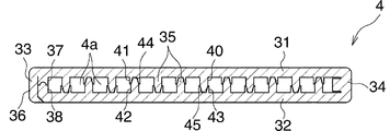
熱交換管(4)は、図7および図8に示すように、互いに対向する平らな上下壁(31)(32)(1対の平坦壁)と、上下壁(31)(32)の前後両側縁どうしにまたがる前後両側壁(33)(34)と、前後両側壁間(33)(34)において上下壁(31)(32)にまたがるとともに長さ方向に伸びかつ相互に所定間隔をおいて設けられた複数の補強壁(35)とよりなり、内部に幅方向に並んだ複数の冷媒通路(4a)を有するものであり、両面にろう材層を有するアルミニウムブレージングシートからなる管製造用金属板を曲げて必要部分をろう付することにより形成されている。 As shown in FIGS. 7 and 8, the heat exchange pipe (4) has flat upper and lower walls (31) and (32) (a pair of flat walls) facing each other and front and rear of the upper and lower walls (31) and (32). The front and rear side walls (33) and (34) straddling both side edges and the front and rear side walls (33) and (34) span the upper and lower walls (31) and (32) and extend in the longitudinal direction with a predetermined distance from each other. And a plurality of reinforcing walls (35) provided, and having a plurality of refrigerant passages (4a) arranged in the width direction inside, and for producing a pipe comprising an aluminum brazing sheet having a brazing filler metal layer on both sides It is formed by bending a metal plate and brazing a necessary part.
前側壁(33)は2重構造であり、上壁(31)の前側縁より下方隆起状に一体成形されかつ熱交換管(4)の全高にわたる外側側壁用凸条(36)と、外側側壁用凸条(36)の内側において上壁(31)より下方隆起状に一体成形された内側側壁用凸条(37)と、下壁(32)の前側縁より上方隆起状に一体成形された内側側壁用凸条(38)とよりなる。外側側壁用凸条(36)は、下端部が下壁(32)の下面前側縁部に係合された状態で両内側側壁用凸条(37)(38)および下壁(32)にろう付されている。両内側側壁用凸条(37)(38)は、相互に突き合わされてろう付されている。後側壁(34)は、上下壁(31)(32)と一体に形成されている。下壁(32)の内側側壁用凸条(38)の先端面に、その長手方向に伸びる凸起(38a)が全長にわたって一体に形成され、上壁(31)の内側側壁用凸条(37)の先端面に、その長手方向に伸びかつ凸起(38a)が圧入される凹溝(37a)が全長にわたって形成されている。 The front side wall (33) has a double structure, and is integrally formed in a raised shape below the front edge of the upper wall (31) and extends over the entire height of the heat exchange pipe (4), and the outer side wall ridge (36), The inner side wall ridges (37) are integrally formed in a bulging shape downward from the upper wall (31) inside the convex ridges (36), and the ridges are integrally formed above the front side edge of the lower wall (32). It consists of the convex for inner side wall (38). The outer side wall ridges (36) are connected to the inner side wall ridges (37) (38) and the lower wall (32) with the lower end engaged with the lower front edge of the lower wall (32). It is attached. Both the inner side wall ridges (37) and (38) are abutted against each other and brazed. The rear side wall (34) is formed integrally with the upper and lower walls (31) (32). A protrusion (38a) extending in the longitudinal direction is integrally formed over the entire length on the front end surface of the inner side wall projection (38) of the lower wall (32), and the inner side wall projection (37) of the upper wall (31) is formed. A concave groove (37a) that extends in the longitudinal direction and into which the protrusion (38a) is press-fitted is formed in the front end surface of
補強壁(35)は、上壁(31)より下方隆起状に一体成形された補強壁用凸条(40)(41)と、下壁(32)より上方隆起状に一体成形された補強壁用凸条(42)(43)とが、相互に突き合わされてろう付されることにより形成されている。上壁(31)および下壁(32)には、それぞれ突出高さの異なる高低2種の補強壁用凸条(40)(41)(42)(43)が前後方向に交互に形成されており、上壁(31)における突出高さの高い補強壁用凸条(40)と下壁(32)における突出高さの低い補強壁用凸条(43)とがろう付され、上壁(31)における突出高さの低い補強壁用凸条(41)と下壁(32)における突出高さの高い補強壁用凸条(42)とがろう付されている。以下、上下両壁(31)(32)の突出高さの高い補強壁用凸条(40)(42)をそれぞれ第1補強壁用凸条といい、同じく低い補強壁用凸条(41)(43)をそれぞれ第2補強壁用凸条というものとする。上下両壁(31)(32)の第2補強壁用凸条(41)(43)の先端面に、その長手方向に伸びかつ他方の壁(32)(31)の第1補強壁用凸条(42)(40)の先端部が嵌る凹溝(44)(45)が全長にわたって形成されており、上下両壁(31)(32)の第1補強壁用凸条(40)(42)の先端部が凹溝(45)(44)内に嵌め入れられた状態で、両補強壁用凸条(40)(43)および(41)(42)がろう付されている。 The reinforcing wall (35) is a reinforcing wall projection (40) (41) integrally formed in a raised shape from the upper wall (31) and a reinforcing wall integrally formed in a raised shape from the lower wall (32). The projecting ridges (42) and (43) are formed by being abutted against each other and brazed. The upper wall (31) and the lower wall (32) are formed with two ridges (40), (41), (42), and (43) for the reinforcing wall alternately in the front-rear direction. The reinforcing wall projections (40) having a high protruding height on the upper wall (31) and the reinforcing wall projections (43) having a low protruding height on the lower wall (32) are brazed, and the upper wall ( The reinforcing wall ridges (41) having a low protruding height in 31) and the reinforcing wall ridges (42) having a high protruding height in the lower wall (32) are brazed. Hereinafter, the ridges (40) and (42) for the reinforcing wall having the high protruding heights of the upper and lower walls (31) and (32) are referred to as the first ridges for the reinforcing wall, respectively, and the ridges for the lower reinforcing wall (41). (43) is referred to as a second reinforcing wall projection. The first reinforcing wall protrusions of the other walls (32) (31) extend in the longitudinal direction on the tip surfaces of the second reinforcing wall protrusions (41) (43) of the upper and lower walls (31) (32). Concave grooves (44) (45) into which the tips of the strips (42) and (40) fit are formed over the entire length, and the first reinforcing wall convex strips (40) and (42) on both the upper and lower walls (31) and (32). ), The reinforcing wall projections (40) (43) and (41) (42) are brazed in a state in which the tip of each of the reinforcing walls is fitted in the concave grooves (45) (44).
熱交換管(4)の両端部は、それぞれ両ヘッダタンク(2)(3)の内側プレート(8)の管挿入穴(18)および中間プレート(9)の連通穴(22)内に挿入されるとともに、その端面が中間プレート(9)の段部(25)に当接した状態で、内側プレート(8)のろう材層および上述した管製造用金属板(50)のろう材層を利用して、内側プレート(8)の管挿入穴(18)および中間プレート(9)の連通穴(22)の内周面にろう付されている。 Both ends of the heat exchange pipe (4) are inserted into the pipe insertion holes (18) of the inner plates (8) of both header tanks (2) (3) and the communication holes (22) of the intermediate plate (9), respectively. In addition, the brazing material layer of the inner plate (8) and the brazing material layer of the metal plate for pipe production (50) described above are used with its end face in contact with the step (25) of the intermediate plate (9). The inner peripheral surface of the pipe insertion hole (18) of the inner plate (8) and the communication hole (22) of the intermediate plate (9) are brazed.
コルゲートフィン(5)は両面にろう材層を有するブレージングシート、ここではアルミニウムブレージングシートを用いて波状に形成されたものである。 The corrugated fin (5) is formed in a wavy shape using a brazing sheet having a brazing filler metal layer on both sides, here an aluminum brazing sheet.
ガスクーラ(1)は、圧縮機、エバポレータ、減圧器およびガスクーラから出てきた冷媒とエバポレータから出てきた冷媒とを熱交換させる中間熱交換器とともに超臨界冷凍サイクルを構成し、カーエアコンとして車両、たとえば自動車に搭載される。 The gas cooler (1) constitutes a supercritical refrigeration cycle together with an intermediate heat exchanger that exchanges heat between the refrigerant that has come out of the compressor and the evaporator, the decompressor and the gas cooler and the refrigerant that has come out of the evaporator. For example, it is installed in a car.
上述したガスクーラ(1)において、圧縮機を通過したCO2 が、入口部材(13)の冷媒流入路(14)を通って冷媒入口(12)から第1ヘッダタンク(2)の入口ヘッダ部(10A)内に入り、分流して第1パス(P1)のすべての熱交換管(4)の冷媒通路(4a)内に流入する。冷媒通路(4a)内に流入したCO2は、冷媒通路(4a)内を左方に流れて第2ヘッダタンク(3)の中間ヘッダ部(20)の流入部(20a)内に流入する。中間ヘッダ部(20)の流入部(20a)内に流入したCO2はその内部を通って下方に流れ、分流して第2パス(P2)のすべての熱交換管(4)の冷媒通路(4a)内に流入し、流れ方向を変えて冷媒通路(4a)内を右方に流れて第1ヘッダタンク(2)の出口ヘッダ部(10B)内に入る。その後、CO2は冷媒出口(15)および出口部材(16)の冷媒流出路(17)を通って流出する。そして、CO2が熱交換管(4)の冷媒通路(4a)内を流れる間に、通風間隙を図1に矢印Xで示す方向に流れる空気と熱交換し、冷却される。CO2が流入部(20a)内を流れる際には、外方膨出部(24)内の冷媒流通部(24a)および中間プレート(9)の冷媒流通部(9c)を流れるが、非膨出部(26)が設けられている部分においては、中間プレート(9)の冷媒流通部(9c)のみを流れるので、抵抗が付与され、中間ヘッダ部(20)の流入部(20a)内における非膨出部(26)よりも下方の部分の圧力は低下する。 In the gas cooler (1) described above, the CO 2 that has passed through the compressor passes through the refrigerant inflow passage (14) of the inlet member (13) from the refrigerant inlet (12) to the inlet header portion (1) of the first header tank (2). 10A), flows into the refrigerant passages (4a) of all the heat exchange pipes (4) in the first path (P1). The CO 2 flowing into the refrigerant passage (4a) flows leftward in the refrigerant passage (4a) and flows into the inflow portion (20a) of the intermediate header portion (20) of the second header tank (3). The CO 2 that has flowed into the inflow portion (20a) of the intermediate header portion (20) flows downward through the inside thereof, and is divided into refrigerant passages (all of the heat exchange pipes (4) in the second path (P2)). 4a), the flow direction is changed, the refrigerant passage (4a) flows to the right and enters the outlet header portion (10B) of the first header tank (2). Thereafter, CO 2 flows out through the refrigerant outlet (15) and the refrigerant outlet path (17) of the outlet member (16). Then, while CO 2 flows in the refrigerant passage (4a) of the heat exchange pipe (4), the ventilation gap is heat-exchanged with the air flowing in the direction indicated by the arrow X in FIG. When CO 2 flows through the inflow part (20a), it flows through the refrigerant circulation part (24a) in the outward bulge part (24) and the refrigerant circulation part (9c) of the intermediate plate (9). In the part where the outlet part (26) is provided, since it flows only through the refrigerant circulation part (9c) of the intermediate plate (9), resistance is given, and in the inflow part (20a) of the intermediate header part (20) The pressure in the portion below the non-bulged portion (26) decreases.
上記超臨界冷凍サイクルの圧縮機においては、通常、摺動部の潤滑のために潤滑油が使用されており、そのため超臨界冷媒中に3〜10質量%程度の潤滑油が必然的に混入しており、この潤滑油がCO2とともに入口ヘッダ部(10A)内に流入するが、上述したように、流入部(20a)内を流れるCO2に抵抗が付与されるので、図9に示すように、第2ヘッダタンク(3)の外方膨出部(24)内、すなわち中間ヘッダ部(20)の流入部(20a)内における非膨出部(26)よりも下方の部分の圧力は低下し、その結果第1ヘッダタンク(2)の入口ヘッダ部(10A)内の圧力と第2ヘッダタンク(3)の中間ヘッダ部(20)の流入部(20a)内の圧力との差圧は、冷媒入口(12)からの距離が大きい場合にも大きくなる。したがって、入口ヘッダ部(10A)内に通じている第1パス(P1)のうち、冷媒入口(12)からの距離が大きい部位、すなわち下端部に配置されている熱交換管(4)内の冷媒流量も、比較的に多くなり、当該熱交換管(4)内への潤滑油の滞留が抑制される。その結果、第1パス(P1)の下端部側に位置する熱交換管(4)における冷媒流量の減少に伴う熱交換性能の悪化が防止され、ガスクーラ(1)全体の熱交換効率の低下が防止される。 In the compressor of the above supercritical refrigeration cycle, lubricating oil is usually used for lubrication of the sliding portion. Therefore, about 3 to 10% by mass of lubricating oil is inevitably mixed in the supercritical refrigerant. This lubricating oil flows into the inlet header portion (10A) together with CO 2 , but as described above, resistance is given to the CO 2 flowing in the inflow portion (20a), as shown in FIG. In addition, the pressure in the outer bulge portion (24) of the second header tank (3), that is, the pressure below the non-bulge portion (26) in the inflow portion (20a) of the intermediate header portion (20) is As a result, the pressure difference between the pressure in the inlet header portion (10A) of the first header tank (2) and the pressure in the inflow portion (20a) of the intermediate header portion (20) of the second header tank (3) Increases even when the distance from the refrigerant inlet (12) is large. Therefore, in the first path (P1) communicating with the inlet header (10A), the distance from the refrigerant inlet (12) is large, that is, in the heat exchange pipe (4) disposed at the lower end. The refrigerant flow rate also increases relatively, and the retention of lubricating oil in the heat exchange pipe (4) is suppressed. As a result, the heat exchange performance in the heat exchange pipe (4) located on the lower end side of the first pass (P1) is prevented from deteriorating, and the overall heat exchange efficiency of the gas cooler (1) is reduced. Is prevented.
図10は第2ヘッダタンク(3)の中間ヘッダ部(20)の流入部(20a)の下部に設けられた抵抗付与手段の変形例を示す。 FIG. 10 shows a modification of the resistance applying means provided at the lower part of the inflow part (20a) of the intermediate header part (20) of the second header tank (3).
図10に示すように、中間プレート(9)における中間ヘッダ部(20)の流入部(20a)の下部と対応する位置において、上下に隣り合う連通穴(22)どうしは連通させられておらず、ここに非連通部(60)が設けられている。そして、この非連通部(60)により抵抗付与手段が構成されている。また、外側プレート(7)の外方膨出部(24)には非膨出部(26)は設けられていない。 As shown in FIG. 10, at the position corresponding to the lower part of the inflow part (20a) of the intermediate header part (20) in the intermediate plate (9), the upper and lower communication holes (22) are not communicated with each other. Here, a non-communication portion (60) is provided. And this non-communication part (60) comprises the resistance provision means. Further, the outer bulging portion (24) of the outer plate (7) is not provided with the non-bulging portion (26).
そして、CO2が流入部(20a)内を流れる際には、外方膨出部(24)内の冷媒流通部(24a)および中間プレート(9)の冷媒流通部(9c)を流れるが、非連通部(60)が設けられている部分においては、外方膨出部(24)内の冷媒流通部(24a)のみを流れるので、抵抗が付与され、中間ヘッダ部(20)の流入部(20a)内における非連通部(60)よりも下方の部分の圧力は低下する。 Then, when the CO 2 flows through the inlet portion (20a) is flowing outward bulging portion (24) refrigerant flow section in (24a) and the refrigerant flow portion of the intermediate plate (9) to (9c), In the portion where the non-communication portion (60) is provided, only the refrigerant circulation portion (24a) in the outward bulge portion (24) flows, so that resistance is provided and the inflow portion of the intermediate header portion (20) The pressure in the part below (20a) below the non-communication part (60) decreases.
図11は第2ヘッダタンク(3)の中間ヘッダ部(20)の流入部(20a)の下部に設けられた抵抗付与手段の他の変形例を示す。 FIG. 11 shows another modification of the resistance applying means provided in the lower part of the inflow portion (20a) of the intermediate header portion (20) of the second header tank (3).
図11に示すように、中間プレート(9)における中間ヘッダ部(20)の流入部(20a)の下部と対応する位置において、上下に隣り合う連通穴(22)どうしは他の連通部(23)よりも前後方向の幅の狭い幅狭連通部(61)より連通させられている。また、外側プレート(7)の外方膨出部(24)には、上述した実施形態の場合と同様に、非膨出部(26)が設けられている。非膨出部(26)は、中間プレート(9)における幅狭連通部(61)の前後両側部分にろう付されている。そして、非膨出部(26)および幅狭連通部(61)により抵抗付与手段が構成されている。 As shown in FIG. 11, in the position corresponding to the lower part of the inflow part (20a) of the intermediate header part (20) in the intermediate plate (9), the upper and lower communication holes (22) are connected to other communication parts (23 ) And a narrow communication part (61) having a narrower width in the front-rear direction. Further, the outer bulging portion (24) of the outer plate (7) is provided with a non-bulging portion (26) as in the case of the above-described embodiment. The non-bulged portion (26) is brazed to both front and rear side portions of the narrow communication portion (61) in the intermediate plate (9). The non-bulged portion (26) and the narrow communication portion (61) constitute a resistance applying means.
そして、CO2が流入部(20a)内を流れる際には、外方膨出部(24)内の冷媒流通部(24a)および中間プレート(9)の冷媒流通部(9c)を流れるが、非膨出部(26)が設けられている部分においては、中間プレート(9)の冷媒流通部(9c)のみを流れるので、抵抗が付与される。また、非膨出部(26)が設けられている部分には幅狭連通部(61)が設けられているので、冷媒流通部(9c)の幅が絞られ、これによっても抵抗が付与される。したがって、中間ヘッダ部(20)の流入部(20a)内における非膨出部(26)よりも下方の部分の圧力は低下する。 Then, when the CO 2 flows through the inlet portion (20a) is flowing outward bulging portion (24) refrigerant flow section in (24a) and the refrigerant flow portion of the intermediate plate (9) to (9c), In the portion where the non-bulged portion (26) is provided, resistance flows because only the refrigerant circulation portion (9c) of the intermediate plate (9) flows. Further, since the narrow communication portion (61) is provided in the portion where the non-bulged portion (26) is provided, the width of the refrigerant circulation portion (9c) is narrowed, and this also provides resistance. The Accordingly, the pressure in the portion below the non-bulged portion (26) in the inflow portion (20a) of the intermediate header portion (20) decreases.
上記実施形態においては、この発明による熱交換器が適用されたガスクーラ(1)における第1ヘッダタンク(2)のヘッダ部(10A)(10B)の数が2であり、第2ヘッダタンク(3)のヘッダ部(20)の数が1であり、パス(P1)(P2)の数が2であるが、これに限定されるものではなく、第1ヘッダタンク(2)のヘッダ部の数が3以上であり、第2ヘッダタンク(3)のヘッダ部の数が第1ヘッダタンク(2)のヘッダ部の数よりも1つ少なく、パスの数が第1ヘッダタンク(2)のヘッダ部の数と同一であってもよい。また、この発明による熱交換器は、第1ヘッダタンクに、その長さ方向に並んだ複数のヘッダ部が設けられ、第2ヘッダタンクに、第1ヘッダタンクのヘッダ部と同数のヘッダ部がその長さ方向に並んで設けられ、第1ヘッダタンクの長さ方向の一端部のヘッダ部に冷媒入口が設けられるとともに、第2ヘッダタンクにおける冷媒入口とは反対側の端部のヘッダ部に冷媒出口が設けられ、すべての熱交換管が、ヘッダタンクの長さ方向に連続して並んだ複数の熱交換管からなりかつ両ヘッダタンクのヘッダ数よりも1つ多い数のパスに区分されているガスクーラに適用される場合もある。 In the above embodiment, the number of header portions (10A) (10B) of the first header tank (2) in the gas cooler (1) to which the heat exchanger according to the present invention is applied is 2, and the second header tank (3 The number of header sections (20) of 1) is 1 and the number of paths (P1) (P2) is 2, but the number of header sections of the first header tank (2) is not limited to this. Is 3 or more, the number of header sections of the second header tank (3) is one less than the number of header sections of the first header tank (2), and the number of passes is the header of the first header tank (2). It may be the same as the number of parts. In the heat exchanger according to the present invention, the first header tank is provided with a plurality of header portions arranged in the length direction, and the second header tank has the same number of header portions as the header portions of the first header tank. Provided side by side in the length direction, a refrigerant inlet is provided at a header portion at one end in the length direction of the first header tank, and at a header portion at the end opposite to the refrigerant inlet in the second header tank. A refrigerant outlet is provided, and all heat exchange tubes are composed of a plurality of heat exchange tubes arranged continuously in the length direction of the header tanks, and are divided into a number of paths one more than the number of headers of both header tanks. It may be applied to the existing gas cooler.
また、上記の実施形態においては、超臨界冷凍サイクルの超臨界冷媒として、CO2が使用されているが、これに限定されるものではなく、エチレン、エタン、酸化窒素などが使用可能である。 In the above embodiment, CO 2 is used as the supercritical refrigerant in the supercritical refrigeration cycle. However, the present invention is not limited to this, and ethylene, ethane, nitric oxide, and the like can be used.
さらに、上記の実施形態においては、熱交換管(4)は、両面にろう材層を有するアルミニウムブレージングシートからなる管製造用金属板を曲げた折り曲げ体からなるが、これに限定されるものではなく、たとえば外周面にろう材層を有するアルミニウム押出形材からなるものであってもよい。 Furthermore, in the above embodiment, the heat exchange tube (4) is composed of a bent body obtained by bending a metal plate for tube production composed of an aluminum brazing sheet having a brazing filler metal layer on both sides, but is not limited thereto. For example, it may be made of an extruded aluminum material having a brazing filler metal layer on the outer peripheral surface.
(1):ガスクーラ(熱交換器)
(2):第1ヘッダタンク
(3):第2ヘッダタンク
(4):熱交換管
(7):外側プレート
(8):内側プレート
(9):中間プレート
(9a)(9b)(9c):冷媒流通部
(10A):入口ヘッダ部
(10B):出口ヘッダ部
(11A)(11B):外方膨出部
(11a)(11b):冷媒流通部
(12):冷媒入口
(18):管挿入穴
(20):中間ヘッダ部
(20a):流入部
(22):連通穴
(23):連通部
(24):外方膨出部
(24a):冷媒流通部
(26):非膨出部(分断部)
(60):非連通部(分断部)
(61):幅狭連通部
(1): Gas cooler (heat exchanger)
(2): First header tank
(3): Second header tank
(4): Heat exchange pipe
(7): Outer plate
(8): Inside plate
(9): Intermediate plate
(9a) (9b) (9c): Refrigerant circulation part
(10A): Entrance header
(10B): Exit header
(11A) (11B): outward bulge
(11a) (11b): Refrigerant distribution part
(12): Refrigerant inlet
(18): Tube insertion hole
(20): Intermediate header
(20a): Inflow part
(22): Communication hole
(23): Communication part
(24): Outward bulge
(24a): Refrigerant Distribution Department
(26): Non-bulged part (divided part)
(60): Non-communication part (parting part)
(61): Narrow communication part
Claims (14)
第2ヘッダタンクのヘッダ部の流入部に、抵抗付与手段が設けられている熱交換器。 A pair of header tanks arranged at a distance from each other, and a plurality of heat exchange pipes arranged in parallel between the header tanks and having both end portions respectively connected to the header tanks. The header tank is provided with a plurality of header portions arranged in the length direction of the header tank, and the header portion at one end portion of the first header tank has an inlet header portion having a refrigerant inlet at the outer end portion in the length direction. In the heat exchanger provided with a header part having an inflow part into which refrigerant flows in from the inlet header part through the heat exchange pipe to the second header tank,
A heat exchanger in which resistance imparting means is provided at the inflow portion of the header portion of the second header tank.
抵抗付与手段が、外方膨出部に一体に形成され、かつ外方膨出部内の冷媒流通部を長さ方向に分断する分断部よりなる請求項1または2記載の熱交換器。 The second header tank is configured by laminating and brazing an outer plate, an inner plate, and an intermediate plate interposed between the two plates, and the outer plate has a length direction of the header tank. An outwardly bulging portion whose opening is closed by the intermediate plate is formed, and a portion corresponding to the outwardly bulging portion of the second header tank is a header portion, and the outwardly bulging portion in the inner plate A plurality of tube insertion holes are formed in the corresponding portion in a penetrating manner at intervals in the length direction, and the intermediate plate communicates with each tube insertion hole of the inner plate into the outer bulging portion of the outer plate. A hole is formed in a penetrating shape, and one end of the heat exchange pipe is inserted into the pipe insertion hole of the inner plate of the second header tank and brazed to the inner plate, and is connected to the refrigerant circulation part in the outer bulge part. The communicating hole of the intermediate plate is communicated by a communicating part formed between adjacent communicating holes in the intermediate plate, and the communicating hole and the communicating part allow the communicating hole to communicate with the refrigerant circulation part of the outward bulging part. A refrigerant circulation part that is communicated and flows in the length direction of the outward bulge part is formed, and an internal space of the header part is formed by the refrigerant circulation part of the outer bulge part and the refrigerant circulation part of the intermediate plate,
The heat exchanger according to claim 1 or 2, wherein the resistance applying means includes a dividing portion that is integrally formed with the outward bulging portion and that divides the refrigerant circulation portion in the outward bulging portion in the length direction.
抵抗付与手段が、第2ヘッダタンクの中間プレートに一体に形成され、かつ中間プレートの冷媒流通部を長さ方向に分断する分断部よりなる請求項1または2記載の熱交換器。 The second header tank is configured by laminating and brazing an outer plate, an inner plate, and an intermediate plate interposed between the two plates, and the outer plate has a length direction of the header tank. An outwardly bulging portion whose opening is closed by the intermediate plate is formed, and a portion corresponding to the outwardly bulging portion of the second header tank is a header portion, and the outwardly bulging portion in the inner plate A plurality of tube insertion holes are formed in the corresponding portion in a penetrating manner at intervals in the length direction, and the intermediate plate communicates with each tube insertion hole of the inner plate into the outer bulging portion of the outer plate. A hole is formed in a penetrating shape, and one end of the heat exchange pipe is inserted into the pipe insertion hole of the inner plate of the second header tank and brazed to the inner plate, and is connected to the refrigerant circulation part in the outer bulge part. The communicating hole of the intermediate plate is communicated by a communicating part formed between adjacent communicating holes in the intermediate plate, and the communicating hole and the communicating part allow the communicating hole to communicate with the refrigerant circulation part of the outward bulging part. A refrigerant circulation part that is communicated and flows in the length direction of the outward bulge part is formed, and an internal space of the header part is formed by the refrigerant circulation part of the outer bulge part and the refrigerant circulation part of the intermediate plate,
The heat exchanger according to claim 1 or 2, wherein the resistance applying means includes a dividing portion that is integrally formed with the intermediate plate of the second header tank and that divides the refrigerant circulation portion of the intermediate plate in the length direction.
抵抗付与手段が、外方膨出部の一部分に設けられた非膨出部からなり、かつ外方膨出部内の冷媒流通部を長さ方向に分断する分断部と、中間プレートに形成され、かつ他の連通部よりも幅狭の連通部とよりなる請求項1または2記載の熱交換器。 The second header tank is configured by laminating and brazing an outer plate, an inner plate, and an intermediate plate interposed between the two plates, and the outer plate has a length direction of the header tank. An outwardly bulging portion whose opening is closed by the intermediate plate is formed, and a portion corresponding to the outwardly bulging portion of the second header tank is a header portion, and the outwardly bulging portion in the inner plate A plurality of tube insertion holes are formed in the corresponding portion in a penetrating manner at intervals in the length direction, and the intermediate plate communicates with each tube insertion hole of the inner plate into the outer bulging portion of the outer plate. A hole is formed in a penetrating shape, and one end of the heat exchange pipe is inserted into the pipe insertion hole of the inner plate of the second header tank and brazed to the inner plate, and is connected to the refrigerant circulation part in the outer bulge part. The communicating hole of the intermediate plate is communicated by a communicating part formed between adjacent communicating holes in the intermediate plate, and the communicating hole and the communicating part allow the communicating hole to communicate with the refrigerant circulation part of the outward bulging part. A refrigerant circulation part that is communicated and flows in the length direction of the outward bulge part is formed, and an internal space of the header part is formed by the refrigerant circulation part of the outer bulge part and the refrigerant circulation part of the intermediate plate,
The resistance applying means is formed of a non-bulged portion provided in a part of the outward bulging portion, and is formed in the intermediate plate, a dividing portion that divides the refrigerant circulation portion in the outward bulging portion in the length direction, And the heat exchanger of Claim 1 or 2 which consists of a communicating part narrower than another communicating part.
Priority Applications (1)
| Application Number | Priority Date | Filing Date | Title |
|---|---|---|---|
| JP2005374269A JP4852307B2 (en) | 2005-12-27 | 2005-12-27 | Heat exchanger |
Applications Claiming Priority (1)
| Application Number | Priority Date | Filing Date | Title |
|---|---|---|---|
| JP2005374269A JP4852307B2 (en) | 2005-12-27 | 2005-12-27 | Heat exchanger |
Publications (2)
| Publication Number | Publication Date |
|---|---|
| JP2007178018A true JP2007178018A (en) | 2007-07-12 |
| JP4852307B2 JP4852307B2 (en) | 2012-01-11 |
Family
ID=38303386
Family Applications (1)
| Application Number | Title | Priority Date | Filing Date |
|---|---|---|---|
| JP2005374269A Expired - Fee Related JP4852307B2 (en) | 2005-12-27 | 2005-12-27 | Heat exchanger |
Country Status (1)
| Country | Link |
|---|---|
| JP (1) | JP4852307B2 (en) |
Cited By (4)
| Publication number | Priority date | Publication date | Assignee | Title |
|---|---|---|---|---|
| JP2009041797A (en) * | 2007-08-07 | 2009-02-26 | Showa Denko Kk | Heat exchanger |
| JP2013015233A (en) * | 2011-06-30 | 2013-01-24 | Daikin Industries Ltd | Heat exchanger |
| CN105229404A (en) * | 2013-05-15 | 2016-01-06 | 三菱电机株式会社 | Cascade type header box, heat exchanger and conditioner |
| CN111895845A (en) * | 2019-05-05 | 2020-11-06 | 浙江三花智能控制股份有限公司 | Header assembly and heat exchanger |
Citations (3)
| Publication number | Priority date | Publication date | Assignee | Title |
|---|---|---|---|---|
| JP2001279289A (en) * | 2000-03-31 | 2001-10-10 | Daikin Ind Ltd | Refrigeration unit using carbon dioxide gas refrigerant |
| JP2002130866A (en) * | 2000-10-24 | 2002-05-09 | Showa Denko Kk | Condenser for air conditioning |
| JP2005300135A (en) * | 2004-03-17 | 2005-10-27 | Showa Denko Kk | Header tank for heat exchanger, and heat exchanger using the same |
-
2005
- 2005-12-27 JP JP2005374269A patent/JP4852307B2/en not_active Expired - Fee Related
Patent Citations (3)
| Publication number | Priority date | Publication date | Assignee | Title |
|---|---|---|---|---|
| JP2001279289A (en) * | 2000-03-31 | 2001-10-10 | Daikin Ind Ltd | Refrigeration unit using carbon dioxide gas refrigerant |
| JP2002130866A (en) * | 2000-10-24 | 2002-05-09 | Showa Denko Kk | Condenser for air conditioning |
| JP2005300135A (en) * | 2004-03-17 | 2005-10-27 | Showa Denko Kk | Header tank for heat exchanger, and heat exchanger using the same |
Cited By (5)
| Publication number | Priority date | Publication date | Assignee | Title |
|---|---|---|---|---|
| JP2009041797A (en) * | 2007-08-07 | 2009-02-26 | Showa Denko Kk | Heat exchanger |
| JP2013015233A (en) * | 2011-06-30 | 2013-01-24 | Daikin Industries Ltd | Heat exchanger |
| CN105229404A (en) * | 2013-05-15 | 2016-01-06 | 三菱电机株式会社 | Cascade type header box, heat exchanger and conditioner |
| CN105229404B (en) * | 2013-05-15 | 2018-07-17 | 三菱电机株式会社 | Laminated type header box, heat exchanger and conditioner |
| CN111895845A (en) * | 2019-05-05 | 2020-11-06 | 浙江三花智能控制股份有限公司 | Header assembly and heat exchanger |
Also Published As
| Publication number | Publication date |
|---|---|
| JP4852307B2 (en) | 2012-01-11 |
Similar Documents
| Publication | Publication Date | Title |
|---|---|---|
| JP4724594B2 (en) | Heat exchanger | |
| US7992401B2 (en) | Evaporator | |
| US7448440B2 (en) | Heat exchanger | |
| JP2007147172A (en) | Heat exchanger | |
| JP2006132920A (en) | Heat exchanger | |
| JP2005326135A (en) | Heat exchanger | |
| JP2006200881A (en) | Heat exchanger | |
| JP2006078163A (en) | Flat tube, plate body for manufacturing flat tube, and heat exchanger | |
| JP4852307B2 (en) | Heat exchanger | |
| JP4122670B2 (en) | Heat exchanger | |
| JP2006170601A (en) | Evaporator | |
| JP2007032952A (en) | Header tank for heat exchanger, and heat exchanger using the same | |
| WO2011049015A1 (en) | Evaporator | |
| JP2007178017A (en) | Heat exchanger | |
| JP5202291B2 (en) | Air conditioner for vehicles | |
| JP2008089188A (en) | Heat exchanger | |
| JP5574737B2 (en) | Heat exchanger | |
| JP2009113625A (en) | Evaporator | |
| KR100606332B1 (en) | Flat tube for heat exchanger for use in air conditioning or refrigeration systems | |
| JP2009299923A (en) | Heat exchanger | |
| JP2007187435A (en) | Heat exchanger | |
| JP2008256234A (en) | Evaporator | |
| JP2006029765A (en) | Heat exchanger | |
| JP2005291693A (en) | Plate-shaped body for manufacturing flat tube, flat tube, heat exchanger and method of manufacturing heat exchanger | |
| JP2006284163A (en) | Integrated heat exchanging device |
Legal Events
| Date | Code | Title | Description |
|---|---|---|---|
| A621 | Written request for application examination |
Free format text: JAPANESE INTERMEDIATE CODE: A621 Effective date: 20080908 |
|
| A977 | Report on retrieval |
Free format text: JAPANESE INTERMEDIATE CODE: A971007 Effective date: 20110225 |
|
| A131 | Notification of reasons for refusal |
Free format text: JAPANESE INTERMEDIATE CODE: A131 Effective date: 20110412 |
|
| A521 | Written amendment |
Free format text: JAPANESE INTERMEDIATE CODE: A523 Effective date: 20110610 |
|
| TRDD | Decision of grant or rejection written | ||
| A01 | Written decision to grant a patent or to grant a registration (utility model) |
Free format text: JAPANESE INTERMEDIATE CODE: A01 Effective date: 20110927 |
|
| A01 | Written decision to grant a patent or to grant a registration (utility model) |
Free format text: JAPANESE INTERMEDIATE CODE: A01 |
|
| A61 | First payment of annual fees (during grant procedure) |
Free format text: JAPANESE INTERMEDIATE CODE: A61 Effective date: 20111024 |
|
| R150 | Certificate of patent or registration of utility model |
Ref document number: 4852307 Country of ref document: JP Free format text: JAPANESE INTERMEDIATE CODE: R150 Free format text: JAPANESE INTERMEDIATE CODE: R150 |
|
| FPAY | Renewal fee payment (event date is renewal date of database) |
Free format text: PAYMENT UNTIL: 20141028 Year of fee payment: 3 |
|
| S111 | Request for change of ownership or part of ownership |
Free format text: JAPANESE INTERMEDIATE CODE: R313113 |
|
| R350 | Written notification of registration of transfer |
Free format text: JAPANESE INTERMEDIATE CODE: R350 |
|
| R250 | Receipt of annual fees |
Free format text: JAPANESE INTERMEDIATE CODE: R250 |
|
| R250 | Receipt of annual fees |
Free format text: JAPANESE INTERMEDIATE CODE: R250 |
|
| R250 | Receipt of annual fees |
Free format text: JAPANESE INTERMEDIATE CODE: R250 |
|
| R250 | Receipt of annual fees |
Free format text: JAPANESE INTERMEDIATE CODE: R250 |
|
| R250 | Receipt of annual fees |
Free format text: JAPANESE INTERMEDIATE CODE: R250 |
|
| LAPS | Cancellation because of no payment of annual fees |