JP2007178002A - Sliding device - Google Patents
Sliding device Download PDFInfo
- Publication number
- JP2007178002A JP2007178002A JP2007023688A JP2007023688A JP2007178002A JP 2007178002 A JP2007178002 A JP 2007178002A JP 2007023688 A JP2007023688 A JP 2007023688A JP 2007023688 A JP2007023688 A JP 2007023688A JP 2007178002 A JP2007178002 A JP 2007178002A
- Authority
- JP
- Japan
- Prior art keywords
- screw shaft
- slider
- track rail
- attached
- support
- Prior art date
- Legal status (The legal status is an assumption and is not a legal conclusion. Google has not performed a legal analysis and makes no representation as to the accuracy of the status listed.)
- Granted
Links
Images


Landscapes
- Details Of Measuring And Other Instruments (AREA)
- Transmission Devices (AREA)
- Bearings For Parts Moving Linearly (AREA)
Abstract
Description
この発明は,例えば,工作機械,各種組立装置,又は試験装置等の直線摺動部に適用されるスライド装置に関する。 The present invention relates to a slide device applied to a linear sliding portion of, for example, a machine tool, various assembly devices, or a test device.
近年,メカトロ技術の発展が目覚ましく,当該技術を支える基礎的且つ汎用的な装置としてスライド装置がある。スライド装置は,現在では,工作機械,半導体製造装置,搬送装置,及び産業用ロボット等の各技術分野の装置に組み込まれて多用されているが,技術の発展と共にその用途は拡大している。そして,スライド装置自体に対しても高精度,高速摺動化,組立容易性,及び汎用化等の要求が益々高まっている。 In recent years, the development of mechatronics technology has been remarkable, and there is a slide device as a basic and general-purpose device that supports the technology. Currently, slide devices are widely used by being incorporated in devices in various technical fields such as machine tools, semiconductor manufacturing devices, transport devices, and industrial robots, but their applications are expanding with the development of technology. Further, demands for high accuracy, high speed sliding, ease of assembly, generalization, etc. are increasing for the sliding device itself.
スライド装置は,一般に,軌道溝を備えた軌道レール,前記軌道レール上を摺動自在なスライダ,前記スライダに設けられたねじ部に螺合するねじ軸,前記ねじ軸の両端部を軸支する支持プレート,いずれか一方の支持プレートに取り付けられ且つ前記ねじ軸を回転する駆動モータを備えている。このスライド装置は,電気・電子的に制御され,直線上を位置決め案内する。 In general, the slide device has a track rail having a track groove, a slider slidable on the track rail, a screw shaft that is screwed into a screw portion provided on the slider, and supports both ends of the screw shaft. A support motor is provided which is attached to one of the support plates and rotates the screw shaft. This slide device is controlled electrically and electronically, and guides positioning on a straight line.
従来のXY位置決めテーブル装置として,図17に示すようなものが知られている。該XY位置決めテーブル装置は,ベッド105上に固定された軌道レール106,軌道レール106上をスライダ113を介して往復動するXテーブル102,Xテーブル102上の支持台114に固定された軌道レール108,軌道レール108上をスライダ107を介して往復動するYテーブル101,ベッド105に取り付けられたX軸用駆動モータ104,及びXテーブル102に取り付けられたY軸用駆動モータ103を有する。更に,XY位置決めテーブル装置は,Y軸用駆動モータ103で回転駆動されるXテーブル102上の支持台114に軸受111を介して回転可能に支持されたボールねじ軸112,及びX軸用駆動モータ104で回転駆動されるベッド105上に軸受110を介して回転可能に支持されたボールねじ軸109を有する。Xテーブル102は,ボールねじ軸109の回転に応じてボールねじ軸109上を移動し,またYテーブル101は,ボールねじ軸112の回転に応じてボールねじ軸112上を移動する。
A conventional XY positioning table device as shown in FIG. 17 is known. The XY positioning table device includes a
従来,ボールねじとリニアガイド装置とを一体的に組み合わせてなるボールねじ一体型リニアガイド装置が知られている。該ボールねじ一体型リニアガイド装置は,凹溝とこの凹溝の両内側面にボール転動溝とを有するガイドレールと,このガイドレール上をボールの転動を介して凹溝内を軸方向に移動可能に遊嵌するナットと,このナットに螺合するボールねじ軸と,前記ねじ軸の両端部を軸支するサポートユニット,一方のサポートユニットに取り付けられ且つ前記ねじ軸を回転する駆動モータを備えている。凹溝は,潤滑及び冷却用の油のための油溜まりとしての機能を有しており,サポートユニットは,この油が漏れるのを防止するため,ガイドレールに対して端面にてシール材を介してボルト止めにて固定されている。また,ナットに固定されたカバーは,ガイドレールの凹溝を覆うように充分な長さを有している(例えば,特許文献1参照)。 Conventionally, a ball screw integrated linear guide device in which a ball screw and a linear guide device are integrally combined is known. The ball screw integrated linear guide device includes a guide rail having a concave groove and ball rolling grooves on both inner side surfaces of the concave groove, and an axial direction in the concave groove via the ball rolling on the guide rail. A nut that is loosely fitted to the nut, a ball screw shaft that is screwed to the nut, a support unit that supports both ends of the screw shaft, and a drive motor that is attached to one of the support units and rotates the screw shaft It has. The concave groove functions as an oil reservoir for lubricating and cooling oil, and the support unit has a sealing material at the end face against the guide rail to prevent this oil from leaking. It is fixed with bolts. Further, the cover fixed to the nut has a sufficient length so as to cover the groove of the guide rail (see, for example, Patent Document 1).
また,テーブルをガイドによって移動可能に支持し且つ送りねじ軸によって移送するテーブル移送装置が知られている。該テーブル移送装置は,断面コ字状を有し内側面に上下2条の転動体転走面を有するガイドレールと,このガイドレール上をボールの転動を介してガイドレール内側面によって挟み込むようにして移動自在に支持されたテーブルと,このテーブルに螺合する送りねじ軸とを備えている。前記送りねじ軸はモータによって回転駆動され,前記送りねじ軸の一端部はガイドレールの一端に設けられた軸受部に回動自在に支持され,前記送りねじ軸の他端部はガイドレールの他端に取り付けられるモータに継手部を介して作動連結されている(例えば,特許文献2又は3参照)。
There is also known a table transfer device that supports a table movably by a guide and transfers the table by a feed screw shaft. The table transfer device has a U-shaped cross section and a guide rail having two upper and lower rolling element rolling surfaces on the inner surface, and the guide rail is sandwiched by the inner surface of the guide rail via ball rolling. The table is movably supported, and a feed screw shaft that is screwed to the table. The feed screw shaft is rotationally driven by a motor, one end of the feed screw shaft is rotatably supported by a bearing provided at one end of the guide rail, and the other end of the feed screw shaft is the other of the guide rail. It is operatively connected to a motor attached to the end via a joint (for example, see
また,送りねじ装置とリニアガイド装置とを一体化したフィードユニット装置が知られている。該フィードユニット装置は,上方が開口した横断面コ字状をなし両内側面に互いに対向する軸方向のボール転動溝を有する長尺のガイドレールと,このガイドレールのボール転動溝に対向するボール転動溝を両外側面に有するナットブロックと,ナットブロックに螺合する送りねじ軸と,ガイドレールに固定され送りねじ軸を回転自在に且つ軸方向移動不能に支持するサポートユニットとを備えている。また,サポートユニットの位置決めについては,サポートユニットに植設したピンをガイドレールのボール転動溝に係合させることにより,サポートユニットのガイドレールへの取付けを簡素化している(例えば,特許文献4参照)。
ところで,近年,送りねじ装置とリニアガイド装置とを一体化したスライド装置としては,電子産業の発達と共にその製造装置や半導体製造装置等の用途が急拡大している。そして各用途及びその規模に合わせて,スライド装置全体を交換することはコスト上昇を招くと共に,交換作業が煩雑且つ長い作業時間を必要とする。したがって,スライド装置のサイズやテーブルの支持・搬送等の性能に変更が生じたとき等に対処するため,サイズや性能が自由に変更できると共に,安価で且つ迅速に交換作業を行うことができるスライド装置が求められている。 By the way, in recent years, as a slide device in which a feed screw device and a linear guide device are integrated, the use of a manufacturing device, a semiconductor manufacturing device, or the like is rapidly expanding with the development of the electronic industry. In addition, replacing the entire slide device in accordance with each application and its scale increases the cost, and the replacement work is complicated and requires a long work time. Therefore, in order to deal with changes in the size of the slide device and the performance of the table support / transport, etc., the slide can be freely changed in size and performance, and can be replaced quickly and inexpensively. A device is sought.
図17に示すXYテーブル装置では,ボールねじ軸109の軸受110が,モータが配置される側では軌道レール106内に,また,モータが配置されない側では軌道レール106の端面に設けられているため,軌道レール106の長さやボールねじ軸の変更だけをするにしても,軸受110の取付けのためのボルト穴の形成やその取付け作業等が煩雑である。
In the XY table apparatus shown in FIG. 17, the bearing 110 of the
上記各公報に開示の装置においても,ねじ軸の両端を軸支するサポート(支持プレート,サポートユニット)はガイドレールの端面に対して取付けられているので,メンテナンスのための分解や組立に際しての作業性及び位置合わせが煩雑になる。更に,ガイドレールの長さを変更する場合に切断した端面にタップ加工によりボルト穴を形成するに際して,ガイドレールを支持台に固定する固定治具を使用する必要があり,加工作業が煩雑となる。また,実公平7−28444号公報には,モータ側のサポートユニットをガイドレールに嵌合させる各種の取付け例が示されているが,嵌合部分を形成することは加工が煩雑となることを意味し,且つサポートユニットの嵌合位置は事実上当初の位置を変更できないことを意味するから,結局,加工精度と組立作業とが煩雑になる。 Even in the devices disclosed in the above publications, the support (support plate, support unit) that supports both ends of the screw shaft is attached to the end surface of the guide rail. And alignment becomes complicated. Furthermore, when changing the length of the guide rail, it is necessary to use a fixing jig that fixes the guide rail to the support base when forming the bolt hole on the cut end face by tapping, which complicates the processing work. . In addition, in Japanese Utility Model Publication No. 7-28444, various mounting examples for fitting the support unit on the motor side to the guide rail are shown. However, forming the fitting portion makes the processing complicated. This means that the fitting position of the support unit means that the initial position cannot be changed in practice, so that the processing accuracy and the assembly work are complicated.
この発明の目的は,上記課題を解決することであり,スライダを軌道レール上で摺動させるためのねじ軸と螺合するナット体をスライダに対して取外し可能とし且つねじ軸の両端部を支持するねじ軸支持体を軌道レールの上面に対して取り付けることによって,スライド装置のメンテナンスや軌道レールの長さ変更に対応して分解・組立作業を簡素化し,且つねじ軸支持体の取付けのための各種作業を簡素化することができるスライド装置を提供することである。 SUMMARY OF THE INVENTION An object of the present invention is to solve the above-mentioned problem, and a nut body screwed with a screw shaft for sliding a slider on a track rail can be removed from the slider and both ends of the screw shaft are supported. By attaching the screw shaft support to the upper surface of the track rail, the disassembly and assembly work can be simplified in response to maintenance of the slide device and the change of the length of the track rail. To provide a slide device capable of simplifying various operations.
この発明は,互いに連結された一対の側部を有する軌道レール,前記軌道レール上を摺動自在なスライダ,前記スライダに取外し可能に取り付けられると共に前記スライダを前記軌道レール上で摺動させるための送りねじ機構を構成するナット体,前記ナット体に螺合するねじ軸,前記ねじ軸の両端部を軸支し且つ前記一対の側部の上面に載置した状態で取り付けられた一対のねじ軸支持体,及び前記ねじ軸支持体のいずれか一方に取り付けられ且つ前記ねじ軸を回転駆動する駆動モータから成るスライド装置において,
前記軌道レールは前記一対の側部と前記一対の側部を連結する底部とによってU字状凹部を形成しており,前記スライダは前記一対の側部に設けられた軌道溝に対応した軌道溝を備えたケーシング,前記両軌道溝間を転走する転動体,前記ケーシングの端面に固定されたエンドキャップ,及び前記エンドキャップの端面に取り付けられたエンドシールを有し,前記スライダは前記軌道レールの前記U字状凹部内を摺動自在であり,前記送りねじ機構は前記ナット体,前記ねじ軸,及び前記ナット体の螺旋溝と前記ねじ軸の螺旋溝との間に介在されるボールを備えたボールねじで構成され,前記ねじ軸の少なくとも一方の前記端部は前記端部を軸支する軸受が嵌着された薄鋼板製の軸受支持金具を前記ねじ軸支持体に固定することによって前記ねじ軸支持体に対して支持されることを特徴とするスライド装置に関する。
The present invention provides a track rail having a pair of side portions connected to each other, a slider slidable on the track rail, and detachably attached to the slider, and for sliding the slider on the track rail. A nut body constituting a feed screw mechanism, a screw shaft screwed into the nut body, a pair of screw shafts attached to both ends of the screw shaft and mounted on the upper surfaces of the pair of side portions In a slide device comprising a support and a drive motor attached to one of the screw shaft support and rotating the screw shaft,
The track rail has a U-shaped recess formed by the pair of side portions and a bottom portion connecting the pair of side portions, and the slider is a track groove corresponding to a track groove provided on the pair of side portions. A rolling element that rolls between the raceway grooves, an end cap fixed to the end surface of the casing, and an end seal attached to the end surface of the end cap, and the slider is the track rail The feed screw mechanism includes a nut interposed between the nut body, the screw shaft, and a spiral groove of the nut body and a spiral groove of the screw shaft. A bearing support fitting made of a thin steel plate to which a bearing for supporting at least one end of the screw shaft is fitted is fixed to the screw shaft support body. Above Flip being supported about a slide and wherein the relative axial support.
このスライド装置は,上記のように構成されているので,メンテナンスやリードやねじ径を変更するために送りねじ機構を交換する場合等,送りねじ機構をスライド装置から取り外す必要が生じたときには,一対の側部の上面に載置した状態で取り付けられた一対のねじ軸支持体を,ねじ軸の軸支を解除した状態で,一対の側部の上方からの操作で軌道レールから取り外す。ねじ軸と共に送りねじ機構を構成するナット体はスライダから取外し自在であるので,スライダ全体をスライド装置から取り外したり取り替えたりすることなく,ねじ軸と螺合したままのナット体をスライダから取り外すことによって,メンテナンスを施したり,別のリードやねじ径を有するねじ軸及びナット体と交換することができる。 Since this slide device is configured as described above, when it is necessary to remove the feed screw mechanism from the slide device, such as when changing the feed screw mechanism for maintenance or changing the lead or screw diameter, The pair of screw shaft supports attached in a state of being placed on the upper surfaces of the side portions are removed from the track rail by operation from above the pair of side portions in a state where the shaft support of the screw shaft is released. Since the nut body that constitutes the feed screw mechanism together with the screw shaft is detachable from the slider, the nut body that remains screwed to the screw shaft can be removed from the slider without removing or replacing the entire slider from the slide device. , Maintenance can be performed or replaced with a screw shaft and nut body having a different lead or screw diameter.
また,このスライド装置では,ボールねじで構成される送りねじ機構は,ねじ軸の雄ねじ部とナット体の雌ねじ部との間に対向して形成される螺旋状の螺旋溝にボールという転がり要素が配置されているため,ねじ軸の駆動時においてねじ軸とスライダとの相対的な移動がスムーズになり,スライダの位置や速度を高精度で定めることが可能となる。スライダは,軌道レールを構成する一対の側部間に,転動体を介してガタツキなく嵌挿される。スライダは,直動転がり案内機構の基本的な構造を有しているので,軌道レールに対してスムーズに動き,スライダの位置や速度を高精度で定めることが可能となる。更に,薄鋼板製の軸受支持金具を用いる軸支持構造は,軸受支持金具の加工及びねじ軸支持体への組立が容易である。 In this slide device, the feed screw mechanism constituted by a ball screw has a rolling element called a ball in a spiral spiral groove formed oppositely between the male screw portion of the screw shaft and the female screw portion of the nut body. Therefore, when the screw shaft is driven, the relative movement between the screw shaft and the slider becomes smooth, and the position and speed of the slider can be determined with high accuracy. The slider is inserted between the pair of side portions constituting the track rail without rattling through the rolling elements. Since the slider has the basic structure of a linear motion rolling guide mechanism, it can move smoothly with respect to the track rail, and the position and speed of the slider can be determined with high accuracy. Furthermore, the shaft support structure using the bearing support bracket made of a thin steel plate is easy to process the bearing support bracket and to assemble the screw shaft support.
また,前記駆動モータは,前記駆動モータの取付け仕様に対応して配設されたモータアタッチメントに取り付けられ,前記モータアタッチメントに圧入固着された圧入リングを前記ねじ軸支持体に形成された取付け孔に嵌合させることにより,前記駆動モータが前記ねじ軸支持体に位置決めされるものである。スライド装置の使用用途に応じてモータの機種も変更される。駆動モータに対応して形成される取付孔等の位置及び大きさ等の取付け仕様も機種に応じて異なるので,ねじ軸支持体の取付けに際して,モータアタッチメントを介在させて仕様の違いによる取付け仕様の差異を吸収するので,モータの交換及び取付けのための構造が簡単化し且つそのための作業性が向上する。また,モータアタッチメントに圧入固着された圧入リングをねじ軸支持体に嵌合させるので,駆動モータのねじ軸支持体に位置決めが容易である。 The drive motor is attached to a motor attachment arranged according to the mounting specification of the drive motor, and a press-fitting ring press-fitted and fixed to the motor attachment is attached to an attachment hole formed in the screw shaft support. By engaging, the drive motor is positioned on the screw shaft support. The motor model is also changed according to the usage of the slide device. The mounting specifications such as the position and size of the mounting holes formed corresponding to the drive motor also differ depending on the model. Therefore, when mounting the screw shaft support, a motor attachment is interposed so that the mounting specifications differ depending on the specifications. Since the difference is absorbed, the structure for replacing and mounting the motor is simplified and the workability for that is improved. Further, since the press-fitting ring press-fitted and fixed to the motor attachment is fitted to the screw shaft support, positioning on the screw shaft support of the drive motor is easy.
また,前記ねじ軸支持体と前記スライダとの対向する端面の少なくとも一方には,薄鋼板の芯金と前記芯金に焼き付けられたゴムとから構成される緩衝作用を有するストッパが取り付けられている。スライダと軸受支持プレートとが衝突したときの衝撃を回避するため,一般には,スライダ又は軸受支持プレートとの対向面に,弾性体から構成されたストッパが,接着剤等で固定されている。このスライド装置における薄鋼板の芯金と芯金に焼き付けられたゴムとから構成されるストッパは,一つの部品としてボルトで固着可能であるので,ストッパの取付け取外しが容易となり,ストッパの交換及び取付作業性が改善される。 Further, a stopper having a buffering action composed of a core metal of a thin steel plate and a rubber baked on the core metal is attached to at least one of the opposing end surfaces of the screw shaft support and the slider. . In order to avoid an impact when the slider and the bearing support plate collide with each other, a stopper made of an elastic body is generally fixed to the surface facing the slider or the bearing support plate with an adhesive or the like. In this sliding device, the stopper composed of a thin metal core and rubber baked onto the core can be secured as a single part with bolts, making it easy to install and remove the stopper, and to replace and install the stopper. Workability is improved.
また,このスライド装置は,前記軌道レールには,前記軌道レールと前記スライダとの間を覆うカバー部と,前記カバー部の外側に一体的に形成され且つ前記スライダの位置を検出するセンサが取り付けられるセンサ取付けレール部とを有しているセンサレールが配設されている。センサレールには,長手方向の必要な任意の位置にセンサを取り付けることができるので,センサの取付け位置の変更やセンサの取付け作業が簡素化される。センサレールを軌道レールに取り付けることによって,カバー部が軌道レールとスライダとの間を覆うため,異物が軌道レールとスライダとの間に入り込むのが防止される。 Further, in the slide device, a cover portion that covers between the track rail and the slider, and a sensor that is integrally formed outside the cover portion and detects the position of the slider are attached to the track rail. A sensor rail having a sensor mounting rail portion is disposed. Since the sensor can be attached to the sensor rail at any required position in the longitudinal direction, the change of the sensor attachment position and the sensor attachment work are simplified. By attaching the sensor rail to the track rail, the cover portion covers the space between the track rail and the slider, so that foreign matter is prevented from entering between the track rail and the slider.
また,前記スライダと前記ねじ軸との上部は,前記ねじ軸支持体間に掛け渡された防塵カバーによって覆われており,前記スライダは,前記防塵カバーの側縁部から上方に延びて搭載物取付け用のフランジ部を有している。防塵カバーは,スライド装置の駆動部分であるスライダとねじ軸との上部を覆うので,上方からの異物の落下,侵入から駆動部分を保護する。特に,一対の側部と底部とで構成した軌道レールのU字状凹部内にスライダを嵌挿させているので,この溝の上部が防塵カバーで略覆われた保護構造となる。防塵カバーを用いる場合には,スライダは,搭載物(搬送物)を支持するために防塵カバーの側縁部から上方に延びる搭載物取付け用のフランジ部を有する構造となる。 The upper part of the slider and the screw shaft is covered with a dust-proof cover spanned between the screw-shaft supports, and the slider extends upward from the side edge of the dust-proof cover. It has a flange for mounting. The dustproof cover covers the upper part of the slider and the screw shaft, which are the drive part of the slide device, and thus protects the drive part from falling and intrusion of foreign matter from above. In particular, since the slider is fitted in the U-shaped concave portion of the track rail constituted by a pair of side portions and the bottom portion, a protective structure is obtained in which the upper portion of the groove is substantially covered with a dustproof cover. When a dustproof cover is used, the slider has a structure having a flange portion for mounting a load that extends upward from the side edge portion of the dustproof cover to support the load (conveyed item).
この発明によるスライド装置は,上記のように構成されているので,次のような効果を有する。即ち,このスライド装置は,互いに連結された一対の側部を有する軌道レール上を摺動自在なスライダに,送りねじ機構を構成するナット体を取外し可能に取り付けておき,ねじ軸をナット体に螺合し,一対の側部の上面に載置した状態で取り付けられた一対のねじ軸支持体によってねじ軸の両端部を軸支し,ねじ軸を回転駆動する駆動モータをねじ軸支持体のいずれか一方に取り付けたので,例えば,メンテナンスの場合やリード又はねじ径を変更するために送りねじ機構を交換する場合等,送りねじ機構をスライド装置から取り外す必要が生じたときには,一対の側部の上面に載置した状態で取り付けられた一対のねじ軸支持体を,ねじ軸の軸支を解除した状態で,一対の側部の上方からの操作で軌道レールから取り外すと,ねじ軸とスライダから取り外したナット体とをスライド装置から簡単に取り外すことができる。したがって,スライド装置自体を交換したり,スライダ全体をスライド装置から取り外したり取り替えたりすることなく,ねじ軸とナット体のみを取り外すことで,各種のメンテナンスを施したり,異なるリード又はねじ径を有する送りねじ機構と交換することができる。 Since the slide device according to the present invention is configured as described above, it has the following effects. That is, this slide device has a slider that is slidable on a track rail having a pair of side portions that are connected to each other, a nut body that constitutes the feed screw mechanism is detachably attached, and the screw shaft is attached to the nut body. A pair of screw shaft supports that are screwed together and mounted on the upper surfaces of the pair of side portions are pivotally supported at both ends of the screw shaft, and a drive motor that rotationally drives the screw shaft is mounted on the screw shaft support. When it is necessary to remove the feed screw mechanism from the slide device, for example, for maintenance or when changing the lead screw mechanism to change the lead or screw diameter, When the pair of screw shaft supports mounted on the upper surface of the shaft is removed from the track rail by operating from above the pair of side portions with the shaft support of the screw shaft released, the screw shaft and And removed nut from Ida can be easily removed from the sliding device. Therefore, various maintenance can be performed by removing only the screw shaft and nut body without changing the slide device itself, or removing or replacing the entire slider from the slide device, and feeding with different leads or screw diameters. Can be replaced with a screw mechanism.
以下,図面を参照して,この発明によるスライド装置の実施例を説明する。図1に示すように,スライド装置1は,基本的に,上面側が開口した断面U字状で長尺な軌道レール2,軌道レール2のU字状凹部5内に移動可能に嵌挿されたスライダ3,スライダ3に螺合するねじ軸4,及び後述する駆動モータ60から構成される。軌道レール2は取付け孔87(後述する)を挿通する取付けボルト等の固着手段によって図示しない支持台に固定され,スライダ3は,図示しない搭載物を取付けボルト等の固着手段によって固定する。スライダ3が軌道レール2に対して移動することにより,搭載物は支持台に対して移動することができる。スライダ3は,軌道レール2との間において直動転がり案内機構を介して摺動自在である。軌道レール2のU字状凹部5は,底部6とその両側から起立する一対の側部7とによって構成されている。即ち,一対の側部7は,底部6によって連結された構造を有している。一対の側部7の対向する内面には,スライダ3が転動する複数のボール10を介して滑らかで正確な直線走行を行うように,一対の軌道溝8が長手方向に平行に延びて形成されており,一対の軌道溝8とボール10とで直動転がり案内機構が構成されている。
Embodiments of a slide device according to the present invention will be described below with reference to the drawings. As shown in FIG. 1 , the
スライダ3は,外周に螺旋溝を有するねじ軸4が螺合する螺旋溝(図示せず)を有するナット体17を備えており,ねじ軸4とナット体17とは,ねじ軸4の回転に応じてスライダ3を軌道レール2の軸方向に直線移動する送りねじ機構を構成している。この実施例では,スライダ3が滑らかで正確に直線送りされるように両螺旋溝の間にボールが転動可能に介在されており,送りねじ機構は,ねじ軸4,ナット体17及びボールを備えたボールねじで構成されている。両螺旋溝に嵌合するボールが循環できるように,ナット体17内には,ボール循環路(図示せず)が形成されている。スライダ3の詳細な構造については,後述する。
The
ねじ軸4の各端部を回転可能に支持するモータ側のねじ軸支持体11とエンド側のねじ軸支持体12(それぞれの構造については後述する)は,アルミニウム合金製であり,軌道レール2の各側部7の上面13に対してタップ加工によって形成されたねじ穴にねじ込まれる取付けねじによって固定されている。軌道レール2の軌道溝8及び上面13は,互いに平行に加工されている。したがって,モータ側ねじ軸支持体11とエンド側ねじ軸支持体12をそのまま軌道レール2の上面13に対して固着すれば,垂直方向(上下方向)の位置合わせをする必要がない。モータ側ねじ軸支持体11とエンド側ねじ軸支持体12とを軌道レール2に対して水平方向(左右方向)の位置合わせだけを行って取り付ければ,スライダ3側の軌道溝9を軌道レール2側の軌道溝8に対応させた状態で,軌道レール2に配置したねじ軸4をスライダ3内に且つスライダ3の摺動方向に正確に配置させることができる。結局,モータ側ねじ軸支持体11とエンド側ねじ軸支持体12との軌道レール2に対する位置合わせを簡単に行うことができる。
A motor-side
モータ側ねじ軸支持体11とエンド側ねじ軸支持体12との軌道レール2への取付けは,取付けボルト14及び取付けボルト15を,それぞれ,モータ側ねじ軸支持体11とエンド側ねじ軸支持体12とに設けられた取付け用の貫通孔を通して軌道レール2に形成されたねじ穴にねじ込むことによって行われる。軌道レール2を途中で切断することによってその長さを調節する場合を含めて,ねじ穴は,軌道レール2の上面13に対して上方からタップ加工によって形成される。したがって,従来のように,固定治具によって軌道レール2を固定した状態で軌道レール2の側部7,7の端面に横方向からねじ穴を加工するのと比較して,加工作業能率が改善される。また,モータ側ねじ軸支持体11とエンド側ねじ軸支持体12とを軌道レール2に取り付けるには,各ねじ軸支持体11,12を軌道レール2の上面13に載置した状態で取付けボルト14,15を軌道レール2にねじ込む作業を行えばよく,垂直方向の位置合わせが不要となり水平方向の位置合わせだけを行えばよい。したがって,軌道レール2の側面に垂直方向(高さ位置)と水平方向(左右位置)とを同時に位置合わせをしながら行う従来の取付け作業と比較して,取付け作業の作業性も改善される。なお,取付けボルト14,15のような,各種の取付け用のボルト又は取付け用の孔(穴)の図面上への符号については,図面での煩雑さを回避するため,一つを代表して記載してある。
The motor-side
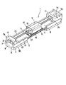
図2には,図1に示したスライド装置1の要部を一部切り欠いた分解斜視図が示されている。スライダ3に形成した貫通孔16には,ねじ軸4に螺合する螺旋溝を有するナット体17の筒部18が嵌合しており,筒部18と一体に形成されているフランジ部19の四隅に設けられた取付け孔を通してねじ軸取付けボルト20をスライダ3にねじ込むことによって,ナット体17がねじ軸4と共にスライダ3に取付けられる。したがって,ねじ軸4のリードを変更する場合やメンテナンス作業を行う場合等,ねじ軸4をスライド装置1から取り外す必要があるときには,ナット体17をスライダ3から分離してねじ軸4をナット体17と共に取り外すだけでよく,スライダ3全体或いは軌道レール2までも含めて取り外す必要はない。また,交換したねじ軸やメンテナンス終了後にねじ軸4をスライド装置1に戻す場合にも,スライダ3は軌道レール2に嵌合したままであるから,ボールねじのスライダ3への装填作業が簡単化される。
FIG. 2 is an exploded perspective view in which a main part of the
モータ側ねじ軸支持体11には,ねじ軸4の縮径されたモータ側端部21を支持するため,次のような軸受け支持構造が設けられている。即ち,モータ側ねじ軸支持体11には,モータ側端部21に対応して軸受孔23が形成されており,軸受孔23内に一対のアンギュラ軸受24,24がシム25を介在させて組み込まれている。アンギュラ軸受24,24の抜出しを防止するため,軸受孔23の両側は軸受押さえ26及び27が配置されている。軸受押さえ26,アンギュラ軸受24,24及び軸受押さえ27を貫通したねじ軸4のモータ側端部21は,更にカラー28を貫通し,ロックナット29によって締め付けられ,その結果,軸受け支持構造が完成すると共に,モータ側端部21が軸受け支持構造に回転自在に支持される。軸受押さえ26は,後述するように,スライダ3がモータ側ねじ軸支持体11に衝突する場合に,衝撃を緩和するストッパともなっている。
The motor side
ねじ軸4のエンド側端部22も,モータ側端部21と同様に縮径されており,次のような軸受け支持構造が設けられている。即ち,エンド側ねじ軸支持体12にはエンド側端部22に対応して軸受孔30が形成されており,軸受孔30内に外側から軸受支持金具34が嵌合されている。軸受孔30内に嵌合された軸受支持金具34内には,軸受31及びE型止め輪32が取り付けられている。軸受支持金具34は,軸受支持金具取付けボルト35によってエンド側ねじ軸支持体12に取付けられる。
The end
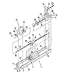
次に,スライダ3の詳細について説明する。図3はスライダ3の分解斜視図である。スライダ3は,側面下部にボール10が転動する軌道溝9と中央長手方向に貫通孔16とを有するケーシング40を備えている。軌道溝9の上面と軌道レール2との隙間は上面シール41によってシールされる。各軌道溝9からケーシング40内に形成した各ボール循環路42を通って或いはその逆の方向に多数のボール10を無限循環させるため,各無限循環路毎に循環溝スペーサ43が一対設けられ,循環溝スペーサ43を含んで方向転換路が形成された一対のエンドキャップ44がケーシング40に対して長手方向の端面に設けられている。エンドキャップ44,44の外側には軌道レール2との隙間をシールする一対のエンドシール45が設けられている。エンドキャップ44とエンドシール45とは,エンドキャップ44とエンドシール45とを貫通してボルト46によりケーシング40に取り付けられる。グリスニップル47が少なくとも一方のエンドシール45を通してエンドキャップ44に接続されて,外部からの潤滑油が各無限循環路内に供給される。また,この場合,他方のエンドキャップ44とエンドシール45とには,潤滑油が漏れるのを封じる止め栓48が設けられている。
Next, details of the
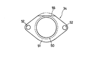
次に,エンド側ねじ軸支持体12におけるねじ軸4の端部22の支持構造について説明する。図4に示すように,エンド側ねじ軸支持体12をねじ軸4の軸線を含む垂直面で切断した断面図で見ると,軸受支持金具34は,軸受31の外輪が嵌合する円筒部50と,円筒部50の外側から径方向に広げられたフランジ部51とから構成されており,エンド側ねじ軸支持体12に組み付けた状態では,フランジ部51の一側がエンド側ねじ軸支持体12の端面に当接される。フランジ部51の両横部は拡大されて,取付けボルト35を挿通する挿通孔52が形成されている。挿通孔52に対応して,エンド側ねじ軸支持体12には取付けボルト35が挿通する挿通孔が形成されている。ストッパ33の中央には段部53が形成されており,段部53はエンド側ねじ軸支持体12の軸受孔30に嵌合している。
Next, the support structure of the
軸受支持金具34をエンド側ねじ軸支持体12に組み付けた状態で,取付けボルト35を軸受支持金具34の挿通孔52を挿通してエンド側ねじ軸支持体12にねじ込むことにより,軸受支持金具34はエンド側ねじ軸支持体12に固定される。ストッパ33は,衝撃を緩和する緩衝材を有しているので,エンド側ねじ軸支持体12に対して接着固定されている。なお,E型止め輪32は,ねじ軸4のエンド側端部22に形成された溝54に係止されて,軸受31がエンド側端部22から抜け出すのを防止している。また,軸受支持金具34のフランジ部51の上縁部はエンド側ねじ軸支持体12の上縁から突出しないように平坦縁55となっている。この軸支持構造は,簡単な構造の薄鋼板製の軸受支持金具34を用いているので,軸受支持金具34それ自体の加工が簡単であると共に,エンド側ねじ軸支持体12への位置合わせと組立とを容易に行うことができる。
With the
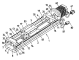
図7〜図11に図示された各構成要素について,図1〜図6に示したものと同様のものには同一符号を付してあるので,再度の説明を省略する。また,スライダ3が支持する搭載物の位置及び荷重に応じて,一つの軌道レール2に複数のスライダ3が配設される。搭載物を支持するのにスライダ3を同じねじ軸4に対して2台用いた例が図7に示されている。図7は,1台のスライダ3を実線で他の1台のスライダ3aを想像線で示すように,2台のスライダ3,3aを最も接近させた状態で並べて設置している。スライダ当たりの支持荷重は過大になることがなく,且つ搭載物の支持点,荷重共にバランス良く支持することができる。また,モータ側ねじ軸支持体11の端板70については,後の駆動モータの取付けに関連して詳述する。軌道レール2の底部6には,軌道レール2を支持台に固定するための取付けボルト(図示せず)が挿通される取付け孔87が二列になって所定間隔に形成されている。図9〜図11に示すように,スライド装置1の軌道レール2の断面における横軸線回り及び縦軸線回りの断面二次モーメントを大きくして軌道レール2の曲げ剛性が高められている。したがって,スライダ3が支持するテーブルの下方向荷重が作用しても,例えば,長手方向に隣接する二つの取付け孔87,87間において最も大きく変位するであろう箇所での軌道レール2に生じる変位量を抑制することができる。
7 to 11, the same components as those shown in FIGS. 1 to 6 are denoted by the same reference numerals, and the description thereof will not be repeated. A plurality of
図1及び図2に示したスライド装置1の軌道レール2,スライダ3,ねじ軸4,モータ側ねじ軸支持体11,及びエンド側ねじ軸支持体12から成る要部に対して駆動モータとセンサとが取り付けられる。図12は,駆動モータとセンサとをスライド装置1の要部に対して取り付けてスライド装置1の組立が完成した状態を示す斜視図である。駆動モータ60は,ステッピングモータであり,モータ用コネクタ61を介してコントローラ(図示せず)から制御電流が入力され,出力軸63(図13参照)に回転を出力する。駆動モータ60は,モータ側ねじ軸支持体11に取付けボルト(図示せず。ねじ軸4の軸方向と平行な方向に取り付ける)によって取り付けられたモータアタッチメント64に取付けボルト65によって取り付けられる。このように,駆動モータ60は,モータ側ねじ軸支持体11に対して,種々の駆動モータの取付仕様に合わせてなるモータアタッチメント64を介して取り付けられるので,モータ側ねじ軸支持体11に対してスライド装置1の使用用途に合わせて出力等の異なる各種駆動モータの取り付けを簡単に行うことができる。
A driving motor and a sensor for the main parts including the
また,駆動モータ60は,軌道レール2の上面13に載置した状態で取り付けられたモータ側ねじ軸支持体11にモータアタッチメント64を介して取り付けられているので,軌道レール2の端面にモータ側ねじ軸支持体を取り付け且つモータ側ねじ軸支持体に駆動モータを取り付ける構造と比較して,駆動モータが軌道レール2から大きく出っ張ることがなく,軌道レール2を支持台(ベース)に取り付けたときに軌道レール2でバランス良く荷重を支持することができる。
Further, since the
図13は図12に示されたスライド装置1に用いられるモータアタッチメントの側面図である。図13に示すように,モータアタッチメント64の中央には貫通孔67が形成されており,貫通孔67の途中まで圧入リング68の一部が圧入されて固着されている。圧入リング68の残る部分は,モータアタッチメント64の貫通孔67からはみ出しており,この部分はモータ側ねじ軸支持体11の端板70に形成された取付け孔71(図1及び図2参照)に嵌合されている。また,駆動モータ60の取付け凸部62が,貫通孔67の残りの部分に嵌合されている。モータアタッチメント64にリング部を一体に形成するよりも,別体に形成した圧入リングを上記のように圧入固定する方が,加工も容易であって精度を出すことができる。駆動モータ60の出力軸63は圧入リング68内を貫通しており,駆動モータ60の出力軸63とねじ軸4のモータ側端部21とは,モータ側ねじ軸支持体11内でカップリング69によって連結されている。
FIG. 13 is a side view of a motor attachment used in the
モータ側ねじ軸支持体11又はエンド側ねじ軸支持体12は,軌道レール2の上面13に載置された状態で取り付けられているので,U字状凹部5に対して,軌道レール2のモータ側又はエンド側の外部から,軌道レール2とねじ軸支持体11,12との間の空間を通して,スライダ3に対して長手方向にアクセスすることができる。このアクセスは,特にエンド側において行い易く且つ有利である。したがって,スライダ3のボール循環路42へ給油するためにエンドキャップ44に設けられたグリースニップル47に対して給油器を接続させようとする場合に,従来のように給油器をスライダ3に対して斜め状に無理な姿勢でアクセスすることなく,給油器をグリースニップル47に正対して無理なく接続することができる。
Since the motor side
スライド装置においては,スライダ3が,万一各ねじ軸支持体11と衝突しても,その時の衝撃による損傷を防止するために,軸受押さえでもなるストッパ26が,軸受押さえ27のような鋼板を芯板としてゴムを焼付けしたものとして予め構成されている。このように,ストッパ26は,芯板にゴムを焼付けた衝撃吸収部材として構成されているので,ボルトにてねじ軸支持体11に取り付けられる。したがって,従来,一般的には弾性体でなるゴム状のストッパがボルトによって直接的に固着することができないために,接着剤によって貼着していたことと比較して,衝撃吸収部材としてのストッパ26を,その芯板を軸受押さえ27と兼用させつつ,ねじ軸支持体11にボルトにて容易に取り付けることができる。なお,ねじ軸支持体11に対して軸受押さえ27を設けた場合には,ストッパ26をスライダ3側に設けてもよい。
In the slide device, even if the
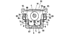
図14は,図12に示すスライド装置1を,図8に示す矢視A−Aと同様の位置と方向で見た断面図,即ち,スライダ3とねじ軸支持体11との間の位置においてねじ軸4に直交する平面で切断した断面図である。図12及び図14を参照すると,軌道レール2の一対の側壁7の外面には,それぞれセンサレール74が取付けボルト75によって取付けられている。各センサレール74には,位置を特定する必要がある任意の位置にセンサ76〜79が設けられている。例えば,センサ76は原点を検出するためのものであり,センサ78は原点前を検出するためのものである。センサ76〜79が検出した検出信号は,リード線81を経てセンサ用コネクタ80からコントローラ(図示せず)に入力される。一方,スライダ3の側面には,ドグ83がドグ取付けボルト84によって取り付けられており,スライダ3がねじ軸4の回転動作で軌道レール2に沿って移動するときに,センサ76〜79がドグ83を検出して,スライダ3の位置の情報をコントローラに送信する。なお,センサ76〜79とセンサ用コネクタ80とを結ぶリード線81は,ナイロンクランプ85によって,モータアタッチメント64に係止させることができる。
14 is a cross-sectional view of the
モータ用コネクタ61とセンサ用コネクタ80とを図示しないドライバと及びコントローラとに接続することにより,コントローラは,センサ用コネクタ80からのドク83を検出した検出信号に基づいて,駆動モータであるステッピングモータ60に制御信号を出力してその出力回転を制御する。図14に示されているように,センサレール74にはその長手方向に延びるリード線用溝86が形成されており,センサ76〜79に接続されるリード線81を収容することができる。また,センサレール74は,軌道レール2とスライダ3と側面部分を覆う防塵カバーにもなっており,幅広いカバー部88とセンサ取付けレール部89とが一体に形成されている。なお,この図において,軌道レール2の底部6には,軌道レール2を支持台(図示せず)に取付ける取付けボルトが挿通する取付け孔87が2列に所定間隔毎に形成されている。
By connecting the
図15は,この発明によるスライド装置の第2実施例であって,軌道レール2内に収容されるスライダ3やねじ軸4を外部から保護する防塵カバー91を設けたスライド装置90を示した斜視図であり,図16は,図15に示すスライド装置の図8に示す矢視A−Aと同様の位置と方向で見た断面図,即ち,スライダ93とねじ軸支持体11との間の位置においてねじ軸4に直交する平面で切断した断面図である。この第2実施例では,スライダの構造が異なる以外は,第1実施例で示したスライド装置1の構造と相違しないので,同一の構造及び同一の機能を有する構成要素には同じ符号を付しており,それらについての再度の説明を省略する。スライダ93は,防塵カバー91との干渉を回避するため,防塵カバー91の両側部を迂回するように,軌道レール2の横方向から上方に延びる一対のフランジ部94,94を有しており,搭載物(図示せず)はフランジ部94,94に取付けねじ穴95にねじ込まれる取付けボルト(図示けず)によって取り付けられる。フランジ部94,94は,スライド装置1におけるドグ83の機能も有している。なお,防塵カバー91は,モータ側ねじ軸支持体11とエンド側ねじ軸支持体12に対して取付けボルト92によって上方から取付けられる。
FIG. 15 is a perspective view showing a
この発明によるスライド装置は,例えば,工作機械,各種組立装置,又は試験装置等の直線摺動部に適用して好ましいものである。 The slide device according to the present invention is preferably applied to a linear sliding portion of, for example, a machine tool, various assembly devices, or a test device.
1,90 スライド装置
2 軌道レール
3,3a,93 スライダ
4 ねじ軸
5 U字状凹部
6 底部
7 側部
8,9 軌道溝
10 ボール
11 モータ側ねじ軸支持体
12 エンド側ねじ軸支持体
13 上面
16 貫通孔
17 ナット体
21 モータ側端部
22 エンド側端部
27 軸受押さえ
24,31 軸受
26,33 ストッパ
34 軸受支持金具
40 ケーシング
42 ボール循環路
44 エンドキャップ
45 エンドシール
47 グリースニップル
60 駆動モータ
64 モータアタッチメント
68 圧入リング
71 取付け孔
74 センサレール
76〜79 センサ
81 リード線
83 ドグ
88 カバー部
89 センサ取付けレール部
91 防塵カバー
94 フランジ部
DESCRIPTION OF
Claims (5)
前記軌道レールは前記一対の側部と前記一対の側部を連結する底部とによってU字状凹部を形成しており,前記スライダは前記一対の側部に設けられた軌道溝に対応した軌道溝を備えたケーシング,前記両軌道溝間を転走する転動体,前記ケーシングの端面に固定されたエンドキャップ,及び前記エンドキャップの端面に取り付けられたエンドシールを有し,前記スライダは前記軌道レールの前記U字状凹部内を摺動自在であり,前記送りねじ機構は前記ナット体,前記ねじ軸,及び前記ナット体の螺旋溝と前記ねじ軸の螺旋溝との間に介在されるボールを備えたボールねじで構成され,前記ねじ軸の少なくとも一方の前記端部は前記端部を軸支する軸受が嵌着された薄鋼板製の軸受支持金具を前記ねじ軸支持体に固定することによって前記ねじ軸支持体に対して支持されることを特徴とするスライド装置。 A track rail having a pair of side portions connected to each other, a slider slidable on the track rail, a removably attached to the slider, and a feed screw mechanism for sliding the slider on the track rail A nut body to be configured, a screw shaft that is screwed into the nut body, a pair of screw shaft supports attached to both ends of the screw shaft and mounted on the upper surfaces of the pair of side portions, and In a slide device comprising a drive motor attached to any one of the screw shaft supports and rotationally driving the screw shaft,
The track rail has a U-shaped recess formed by the pair of side portions and a bottom portion connecting the pair of side portions, and the slider is a track groove corresponding to a track groove provided on the pair of side portions. A rolling element that rolls between the raceway grooves, an end cap fixed to the end surface of the casing, and an end seal attached to the end surface of the end cap, and the slider is the track rail The feed screw mechanism includes a nut interposed between the nut body, the screw shaft, and a spiral groove of the nut body and a spiral groove of the screw shaft. A bearing support fitting made of a thin steel plate to which a bearing for supporting at least one end of the screw shaft is fitted is fixed to the screw shaft support body. Above Flip slide apparatus characterized by being supported with respect to the shaft support.
Priority Applications (1)
| Application Number | Priority Date | Filing Date | Title |
|---|---|---|---|
| JP2007023688A JP4796516B2 (en) | 2007-02-02 | 2007-02-02 | Slide device |
Applications Claiming Priority (1)
| Application Number | Priority Date | Filing Date | Title |
|---|---|---|---|
| JP2007023688A JP4796516B2 (en) | 2007-02-02 | 2007-02-02 | Slide device |
Related Parent Applications (1)
| Application Number | Title | Priority Date | Filing Date |
|---|---|---|---|
| JP19640397A Division JP3927285B2 (en) | 1997-07-08 | 1997-07-08 | Slide device |
Publications (2)
| Publication Number | Publication Date |
|---|---|
| JP2007178002A true JP2007178002A (en) | 2007-07-12 |
| JP4796516B2 JP4796516B2 (en) | 2011-10-19 |
Family
ID=38303373
Family Applications (1)
| Application Number | Title | Priority Date | Filing Date |
|---|---|---|---|
| JP2007023688A Expired - Lifetime JP4796516B2 (en) | 2007-02-02 | 2007-02-02 | Slide device |
Country Status (1)
| Country | Link |
|---|---|
| JP (1) | JP4796516B2 (en) |
Cited By (9)
| Publication number | Priority date | Publication date | Assignee | Title |
|---|---|---|---|---|
| JP2010263107A (en) * | 2009-05-08 | 2010-11-18 | Toray Eng Co Ltd | Multi-axial workpiece transfer method and device therefor |
| KR200488894Y1 (en) * | 2017-09-20 | 2019-04-01 | 티비아이 모션 테크놀로지 컴퍼니 리미티드 | Linear motion module |
| KR20190104698A (en) * | 2018-03-02 | 2019-09-11 | 하이윈 테크놀로지스 코포레이션 | Dustproof device for linear actuator |
| CN110712015A (en) * | 2019-10-27 | 2020-01-21 | 上海诺银机电科技有限公司 | Ball screw capable of running stably under extraordinary environment and preparation method thereof |
| CN112775682A (en) * | 2021-02-04 | 2021-05-11 | 成都福誉科技有限公司 | Integrated form guide rail |
| CN113685437A (en) * | 2021-07-23 | 2021-11-23 | 丽水市杰祥科技有限公司 | Linear guide rail assembly capable of being installed quickly |
| US11319996B2 (en) * | 2018-12-26 | 2022-05-03 | Thk Co., Ltd. | Sensor attachment structure for roller guiding device |
| CN116372534A (en) * | 2023-05-26 | 2023-07-04 | 廊坊精雕数控机床制造有限公司 | Ball screw assembly method based on machine tool |
| CN117092073A (en) * | 2023-10-20 | 2023-11-21 | 南京金铭新型装饰材料有限公司 | Floor appearance detection device |
Citations (10)
| Publication number | Priority date | Publication date | Assignee | Title |
|---|---|---|---|---|
| JPS5148545U (en) * | 1974-10-09 | 1976-04-12 | ||
| JPS61108520U (en) * | 1984-12-21 | 1986-07-09 | ||
| JPS62200016A (en) * | 1986-02-28 | 1987-09-03 | Tsubakimoto Seiko:Kk | Rectilinear motion ball bearing with built-in ball screw |
| JPS6345420U (en) * | 1986-09-10 | 1988-03-26 | ||
| JPS63190935A (en) * | 1987-02-04 | 1988-08-08 | Ogura Clutch Co Ltd | Normally and reversely rotating clutch |
| JPS6443230A (en) * | 1987-08-10 | 1989-02-15 | Nippon Telegraph & Telephone | Line of sight detection apparatus and line of sight input apparatus using the same |
| JPH01113557U (en) * | 1988-01-26 | 1989-07-31 | ||
| JPH0314353U (en) * | 1989-06-26 | 1991-02-13 | ||
| JPH04135187A (en) * | 1990-09-25 | 1992-05-08 | Yamaha Motor Co Ltd | Orthogonal co-ordinate assembling type robot |
| JPH08251863A (en) * | 1995-03-08 | 1996-09-27 | Smc Corp | Electric actuator |
-
2007
- 2007-02-02 JP JP2007023688A patent/JP4796516B2/en not_active Expired - Lifetime
Patent Citations (10)
| Publication number | Priority date | Publication date | Assignee | Title |
|---|---|---|---|---|
| JPS5148545U (en) * | 1974-10-09 | 1976-04-12 | ||
| JPS61108520U (en) * | 1984-12-21 | 1986-07-09 | ||
| JPS62200016A (en) * | 1986-02-28 | 1987-09-03 | Tsubakimoto Seiko:Kk | Rectilinear motion ball bearing with built-in ball screw |
| JPS6345420U (en) * | 1986-09-10 | 1988-03-26 | ||
| JPS63190935A (en) * | 1987-02-04 | 1988-08-08 | Ogura Clutch Co Ltd | Normally and reversely rotating clutch |
| JPS6443230A (en) * | 1987-08-10 | 1989-02-15 | Nippon Telegraph & Telephone | Line of sight detection apparatus and line of sight input apparatus using the same |
| JPH01113557U (en) * | 1988-01-26 | 1989-07-31 | ||
| JPH0314353U (en) * | 1989-06-26 | 1991-02-13 | ||
| JPH04135187A (en) * | 1990-09-25 | 1992-05-08 | Yamaha Motor Co Ltd | Orthogonal co-ordinate assembling type robot |
| JPH08251863A (en) * | 1995-03-08 | 1996-09-27 | Smc Corp | Electric actuator |
Cited By (13)
| Publication number | Priority date | Publication date | Assignee | Title |
|---|---|---|---|---|
| JP2010263107A (en) * | 2009-05-08 | 2010-11-18 | Toray Eng Co Ltd | Multi-axial workpiece transfer method and device therefor |
| KR200488894Y1 (en) * | 2017-09-20 | 2019-04-01 | 티비아이 모션 테크놀로지 컴퍼니 리미티드 | Linear motion module |
| KR20190104698A (en) * | 2018-03-02 | 2019-09-11 | 하이윈 테크놀로지스 코포레이션 | Dustproof device for linear actuator |
| KR102038349B1 (en) | 2018-03-02 | 2019-10-30 | 하이윈 테크놀로지스 코포레이션 | Dustproof device for linear actuator |
| US11319996B2 (en) * | 2018-12-26 | 2022-05-03 | Thk Co., Ltd. | Sensor attachment structure for roller guiding device |
| CN110712015A (en) * | 2019-10-27 | 2020-01-21 | 上海诺银机电科技有限公司 | Ball screw capable of running stably under extraordinary environment and preparation method thereof |
| CN112775682A (en) * | 2021-02-04 | 2021-05-11 | 成都福誉科技有限公司 | Integrated form guide rail |
| CN113685437A (en) * | 2021-07-23 | 2021-11-23 | 丽水市杰祥科技有限公司 | Linear guide rail assembly capable of being installed quickly |
| CN113685437B (en) * | 2021-07-23 | 2023-06-09 | 丽水市杰祥科技有限公司 | Linear guide rail assembly capable of being quickly installed |
| CN116372534A (en) * | 2023-05-26 | 2023-07-04 | 廊坊精雕数控机床制造有限公司 | Ball screw assembly method based on machine tool |
| CN116372534B (en) * | 2023-05-26 | 2023-08-01 | 廊坊精雕数控机床制造有限公司 | Ball screw assembly method based on machine tool |
| CN117092073A (en) * | 2023-10-20 | 2023-11-21 | 南京金铭新型装饰材料有限公司 | Floor appearance detection device |
| CN117092073B (en) * | 2023-10-20 | 2023-12-26 | 南京金铭新型装饰材料有限公司 | Floor appearance detection device |
Also Published As
| Publication number | Publication date |
|---|---|
| JP4796516B2 (en) | 2011-10-19 |
Similar Documents
| Publication | Publication Date | Title |
|---|---|---|
| JP3927285B2 (en) | Slide device | |
| JP4796516B2 (en) | Slide device | |
| US6722289B2 (en) | Table system with angular position controls | |
| US7878082B2 (en) | Sliding device for use in confined spaces | |
| US20100206599A1 (en) | Machine-tool spindle head | |
| US5678928A (en) | Linear motion rolling guide unit | |
| CN108386447B (en) | Rigid-flexible coupling sliding block and motion platform | |
| WO2019117152A1 (en) | Diagnosis system for ball screw unit, and motor control system | |
| JP2003194057A (en) | Rectilinear guide unit equipped with separator between rolling elements | |
| CN202057488U (en) | High-speed ball screw performance test bed capable of replace screw | |
| JP2003247543A (en) | Linear movement guide unit | |
| CN114589568A (en) | High-precision adjustable gear machining equipment | |
| CN2536348Y (en) | Unitary platform with movements in two dimensions | |
| TW201629370A (en) | Feed screw device | |
| JPH09239635A (en) | Xy positioning table device | |
| JP2003239963A (en) | Linear motion guide unit | |
| CN201193690Y (en) | Ball screw rod device | |
| JP5394831B2 (en) | Ball screw drive | |
| JP2013234692A (en) | Driving device using screw mechanism | |
| JP2003227516A (en) | Bearing unit | |
| CN217713538U (en) | Double-axis-center linear module with adjustable gap and pre-pressure | |
| JPH09103931A (en) | Dust preventing method of positioning error absorber | |
| CN117366183A (en) | Optical machine driving mechanism and optical machine | |
| CN209786952U (en) | Electronic jar of no back clearance | |
| CN220288588U (en) | Outer diameter detection mechanism for automatic detection of bearing |
Legal Events
| Date | Code | Title | Description |
|---|---|---|---|
| A977 | Report on retrieval |
Free format text: JAPANESE INTERMEDIATE CODE: A971007 Effective date: 20100630 |
|
| A131 | Notification of reasons for refusal |
Free format text: JAPANESE INTERMEDIATE CODE: A131 Effective date: 20100810 |
|
| A521 | Written amendment |
Free format text: JAPANESE INTERMEDIATE CODE: A523 Effective date: 20101005 |
|
| A131 | Notification of reasons for refusal |
Free format text: JAPANESE INTERMEDIATE CODE: A131 Effective date: 20101221 |
|
| A521 | Written amendment |
Free format text: JAPANESE INTERMEDIATE CODE: A523 Effective date: 20110215 |
|
| A131 | Notification of reasons for refusal |
Free format text: JAPANESE INTERMEDIATE CODE: A131 Effective date: 20110412 |
|
| A521 | Written amendment |
Free format text: JAPANESE INTERMEDIATE CODE: A523 Effective date: 20110609 |
|
| TRDD | Decision of grant or rejection written | ||
| A01 | Written decision to grant a patent or to grant a registration (utility model) |
Free format text: JAPANESE INTERMEDIATE CODE: A01 Effective date: 20110726 |
|
| A01 | Written decision to grant a patent or to grant a registration (utility model) |
Free format text: JAPANESE INTERMEDIATE CODE: A01 |
|
| A61 | First payment of annual fees (during grant procedure) |
Free format text: JAPANESE INTERMEDIATE CODE: A61 Effective date: 20110729 |
|
| R150 | Certificate of patent or registration of utility model |
Free format text: JAPANESE INTERMEDIATE CODE: R150 |
|
| FPAY | Renewal fee payment (event date is renewal date of database) |
Free format text: PAYMENT UNTIL: 20140805 Year of fee payment: 3 |
|
| R250 | Receipt of annual fees |
Free format text: JAPANESE INTERMEDIATE CODE: R250 |
|
| EXPY | Cancellation because of completion of term |