JP2007176183A - Ink film reel and ink film securing device - Google Patents
Ink film reel and ink film securing device Download PDFInfo
- Publication number
- JP2007176183A JP2007176183A JP2007046131A JP2007046131A JP2007176183A JP 2007176183 A JP2007176183 A JP 2007176183A JP 2007046131 A JP2007046131 A JP 2007046131A JP 2007046131 A JP2007046131 A JP 2007046131A JP 2007176183 A JP2007176183 A JP 2007176183A
- Authority
- JP
- Japan
- Prior art keywords
- reel
- ink film
- axial direction
- supply reel
- support
- Prior art date
- Legal status (The legal status is an assumption and is not a legal conclusion. Google has not performed a legal analysis and makes no representation as to the accuracy of the status listed.)
- Pending
Links
Images


Landscapes
- Impression-Transfer Materials And Handling Thereof (AREA)
Abstract
Description
本発明は、ファクシミリ、プリンタおよび複写機などの画像印刷機能を有する通信装置および情報処理装置に搭載されるライン印字式の熱転写型印刷装置に好適に実施することができるインクフィルムリールおよびインクフィルム保持装置に関する。 The present invention relates to an ink film reel and an ink film holding device which can be suitably implemented in a communication device having an image printing function such as a facsimile, a printer, and a copying machine, and a line printing type thermal transfer printing device mounted in an information processing device. .
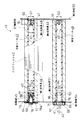
図8は、従来の技術のインクフィルムリールを備えるインクフィルム保持装置1を示す分解斜視図である。この保持装置1は、インクフィルム2が巻回されるインクフィルムリールである供給リール3と、供給リール3の軸線方向一端部に装着される第1支持具4と、供給リール3の軸線方向他端部に装着される第2支持具5と、供給リール3と平行に配置され、供給リール3から巻出されたインクフィルム2を巻き取るインクフィルムリールである巻取リール6と、巻取リール6の軸線方向一端部に装着される第3支持具7と、巻取リール6の軸線方向他端部に装着される第4支持具8と、第3支持具7をその軸線まわりに予め定める巻取方向Aに回転駆動する回転駆動源9とを有する。
FIG. 8 is an exploded perspective view showing an ink film holding device 1 having a conventional ink film reel. The holding device 1 includes a
第1支持具4は、直円筒状の筒部11と、筒部11の軸線方向両端部間の中間部に固定される円環状フランジ12と、筒部11の軸線方向一端部に固定される歯車13とを有する。第2支持具5は、直円筒状の筒部15と、筒部15の軸線方向両端部間の中間部に固定される円環状のフランジ16とを有する。第3支持具7は、直円筒状の筒部18と、筒部18の軸線方向両端部間の中間部に固定される円環状のフランジ19とを有する。第4支持具8は、直円筒状の筒部21と、筒部21の軸線方向両端部間の中間部に固定される円環状のフランジ22と、筒部21の軸線方向一端部に固定される歯車23とを有する。
The
第4支持具8の歯車23には、前記回転駆動源9の図示しない歯車が噛合し、印刷速度に同期して、巻取リール6を巻取り方向Aに回転させて、供給リール3から引出された転写後のインクフィルム2を巻き取ることができるように構成される。また、前記第1支持具4の歯車13には、図示しないバックテンション機構の歯車35が噛合し、印刷時にインクフィルム2に一定の張力を与え、インクフィルム2のたるみや皺の発生を防止している。
The gear 23 (not shown) of the
前記供給リール3および巻取リール6は、相互に間隔をあけて平行に配置され、これらの供給リール3および巻取リール6の各軸線方向の両側には、側板25,26が前記各軸線に垂直に配置される。各側板25,26には、上方(図8の上方)に開放した略U字状の切欠き27〜30が形成される。各切欠き27〜30には、第1〜第4支持具4,5,7,8の各筒部11,15,18,21が着脱自在に嵌まり込む。
The
これらの筒部11,15,18,21の各側板25,26から相互に対向する各内面31,32から内側に突出する部分は、前記供給リール3および巻取リール6の各軸線方向両端部に嵌まり込む。この状態では、第1〜第4支持具4,5,7,8の各フランジ12,16,19,22が各側板25,26の外側に臨む各外面34,35によって支持され、第1および第2支持具4,5は、供給リール3と共通な軸線をなして、インクフィルム2が巻回された供給リール3を回転自在に支持し、第3および第4支持具7,8は、巻取リールと共通な軸線をなして、インクフィルム2が巻回された巻取リール6を回転自在に支持している。
The portions projecting inwardly from the inner surfaces 31, 32 facing each other from the
このような保持装置1は、印刷機能を有するたとえばファクシミリなどの通信装置ならびにプリンタおよび複写機などの情報処理装置に装備されるライン印字式の熱転写型印刷装置に搭載される。 Such a holding device 1 is mounted on a line printing type thermal transfer printing device equipped in a communication device having a printing function such as a facsimile and an information processing device such as a printer and a copying machine.
他の従来の技術は、特許文献1に示されている。この従来の技術では、2枚の側板と、インクフィルムが巻回される供給リールと、供給リールから導かれるインクフィルムを巻き取る巻取リールと、供給リールおよび巻取リールの各軸線方向両端部にそれぞれ装着される4つの支持具と、供給リールおよび巻取リールの各軸線方向両端部に装着された各支持具を保持する2枚の側板と有し、各支持具を各側板の相互に対向する内面側にそれぞれ設けて、各支持具が各側板の外側面から突出しない一体構造とし、これによって保持装置の小形化を図るとともに、インクフィルムの交換作業を容易化することができるように構成されている。 Another conventional technique is disclosed in Patent Document 1. In this conventional technique, two side plates, a supply reel on which an ink film is wound, a take-up reel for winding up an ink film guided from the supply reel, and both axial ends of the supply reel and the take-up reel, respectively. There are four support tools to be mounted, and two side plates for holding the support tools mounted at both axial ends of the supply reel and the take-up reel, and the support tools are opposed to each other. Provided on the inner surface side, each support tool has an integrated structure that does not protrude from the outer surface of each side plate, thereby reducing the size of the holding device and facilitating the ink film replacement operation. Yes.
さらに他の従来の技術は、特許文献2に示されている。この従来の技術では、2枚の側板と、インクフィルムが巻回される供給リールと、供給リールから導かれるインクフィルムを巻き取る巻取リールと、供給リールおよび巻取リールの各軸線方向両端部に装着される4つの支持具と、供給リールおよび巻取リールの各軸線方向両端部に装着された各支持具を保持する2枚の側板と有し、前記4つの支持具のうちの片側に配置される歯車付きの2つの支持具を、一方の側板に歯車とフランジとによって前記一方の側板を挟むようにして傾動自在に取付け、これによってインクフィルムの交換時に、他方の側板に装着される各支持具だけを着脱して、供給リールおよび巻取リールの取外し作業および取付け作業を容易化することができるように構成されている。
Still another conventional technique is disclosed in
上記の図8に示される従来の技術では、インクフィルムの交換時に、供給リール3の軸線方向両端部および巻取リール6の軸線方向両端部の合計4箇所に対して、第1〜第4支持具4,5,7,8の取外し作業および取付け作業を行なわなければならず、これらの作業に手間を要し、インクフィルム交換の作業性が悪いという問題がある。またこの従来の技術では、供給リール側の第1支持具にバックテンションを与えるために、装置本体に前記バックテンションを与えるための機構として回転駆動源9が設けられているため、部品点数が多く、装置本体内の占有空間が大きくなるために装置が大形化してしまうという問題がある。
In the prior art shown in FIG. 8 above, the first to fourth support members are provided for a total of four locations at both ends in the axial direction of the
また、上記の特許文献1に示される従来の技術では、各側板に支持具をそれぞれ設けて一体構造とされるので、インクフィルムの交換時に、供給リールおよび巻取リールの各軸線方向一端部側に装着される各支持具と、供給リールおよび巻取リールの各軸線方向他端部側に設けられる各支持具とは、側板にそれぞれ装着された状態で、供給リールおよび巻取リールに対する取外し作業および取付け作業を行なう必要があり、これらの作業では側板と支持具とを片手で同時に把持しなければならず、操作性が悪く、インクフィルムの交換に手間を要するという問題がある。またこの従来の技術においても、上記の図8の従来の技術と同様に、バックテンション機構を装置本体に設ける必要があるため、部品点数が多く、装置本体内の占有空間が大きくなるために装置が大形化してしまうという問題がある。 Further, in the conventional technique shown in the above-mentioned Patent Document 1, since each side plate is provided with a support member to form an integrated structure, when the ink film is replaced, the supply reel and the take-up reel are arranged at one end in the axial direction. Each support tool to be mounted and each support tool provided on the other end side in the axial direction of the supply reel and the take-up reel are respectively attached to the side plate and removed from the supply reel and the take-up reel. It is necessary to perform attachment work. In these work, the side plate and the support must be gripped at the same time with one hand, so that the operability is poor, and there is a problem that it takes time to replace the ink film. Also in this conventional technique, the back tension mechanism needs to be provided in the apparatus main body as in the conventional technique of FIG. 8 described above, so that the number of parts is large and the occupied space in the apparatus main body becomes large. Has the problem of becoming larger.
さらに、上記の特許文献2に示される従来の技術では、供給リールおよび巻取リールの各軸線方向一端部に装着される2つの支持具は一方の側板に設けられているため、インクフィルムの交換時に、前記軸線方向一端部側に配置される片側の各支持具については、供給リールおよび巻取リールに対して取外し、かつ取付ける必要がないものの、これらの支持具は側板に対して傾動自在に緩やかに取付けられているため、取付け時において、側板に固定的には取付けられていない各支持具に対して、供給リールおよび巻取リールの各軸線方向一端部の向きを正確に位置決めした状態を維持しながら装着しなければならず、操作性が悪く、インクフィルムの交換に手間を要するという問題がある。また、この従来の技術においても、上記の図8および特許文献1に示される各従来の技術と同様に、バックテンション機構を装置本体に設ける必要があるため、部品点数が多く、装置本体内の占有空間が大きくなるために装置が大形化してしまうという問題がある。
Furthermore, in the conventional technique shown in the above-mentioned
さらに、上記の図8、特許文献1および特許文献2に示される各従来の技術では、供給リールおよび巻取リールは大略的に直円筒状の筒体であり、また各支持具は、前記供給リールおよび巻取リールの各軸線方向両端部に嵌まり込む円柱状の嵌合部と、供給リールおよび巻取リールの各軸線方向両端部の各端面が当接するフランジと、側板に支持される軸受部とを有する。
Further, in each of the conventional techniques shown in FIG. 8 and Patent Document 1 and
このような支持具によって、前記供給リールおよび巻取リールの各軸線方向両端部が各側板に回転自在に支持されているため、供給リールの軸線方向両端部の各端面と各側板との間および巻取リールの軸線方向両端部の各端面と各側板との間には、フランジと、供給リールおよび巻取リールの回転を許容できる程度の僅かな隙間とが存在する。このような構成によって、各側板の装置本体への配置上の間隔が決定されてしまうため、装置本体に各側板を前記間隔をあけて配置することができるスペースを確保しなければならず、装置を小形化することができないという問題がある。 Since both ends in the axial direction of the supply reel and the take-up reel are rotatably supported by the side plates by such a support tool, between the end surfaces of the both ends in the axial direction of the supply reel and the side plates and Between each end face of the both ends in the axial direction of the take-up reel and each side plate, there are a flange and a slight gap that allows the supply reel and the take-up reel to rotate. With such a configuration, since the interval on the arrangement of the side plates to the apparatus main body is determined, a space in which the side plates can be arranged at the intervals in the apparatus main body must be secured. There is a problem that cannot be miniaturized.
本発明の目的は、インクフィルム交換時の作業性の向上し、装置を小形化することができるインクフィルムリールおよびインクフィルム保持装置を提供することである。 An object of the present invention is to provide an ink film reel and an ink film holding device that can improve workability at the time of ink film replacement and can downsize the apparatus.
本発明は、インクフィルムが巻回される直円筒状のリール本体を有し、このリール本体の軸線方向両端部が、前記インクフィルムを用いて印刷する装置本体に、支持具によって前記軸線まわりに回転自在に支持されるインクフィルムリールにおいて、
前記リール本体の軸線方向他端部には、その軸線方向他端部の端面よりも軸線方向一端部寄りに退避して前記リール本体内に設けられ、前記支持具の先端部によって前記軸線まわりに回転自在に前記リール本体を支持するための軸受部を備えたことを特徴とするインクフィルムリールである。
The present invention has a right cylindrical reel body around which an ink film is wound, and both axial end portions of the reel body are rotatable around the axis line by a support on an apparatus body that prints using the ink film. In the ink film reel supported by
The other end portion in the axial direction of the reel body is provided in the reel body by being retracted closer to the one end portion in the axial direction than the end face of the other end portion in the axial direction. An ink film reel comprising a bearing portion for rotatably supporting the reel body.
また本発明は、インクフィルムが巻回される供給リールと、供給リールから供給されるインクフィルムを巻き取る巻取リールとを含み、巻取リールおよび供給リールの各軸線方向両端部が、前記インクフィルムを用いて印刷する装置本体に、それぞれ支持具によって前記軸線まわりに回転自在に支持されるインクフィルムリールにおいて、
前記供給リールには、その軸線方向他端部の端面よりも軸線方向一端部寄りに退避して軸受部が設けられ、この軸受部が前記支持具の先端部によって前記軸線まわりに回転自在に支持されることを特徴とするインクフィルムリールである。
The present invention also includes a supply reel on which the ink film is wound, and a take-up reel that winds up the ink film supplied from the supply reel. Both ends in the axial direction of the take-up reel and the supply reel use the ink film. In an ink film reel that is rotatably supported around the axis by a support tool,
The supply reel is provided with a bearing portion retracted closer to one end in the axial direction than the end face of the other end in the axial direction, and the bearing is supported rotatably around the axis by the tip of the support. The ink film reel is characterized by the above.
さらに本発明は、前記供給リールの内径と前記巻取リールの内径とが互いに異なることを特徴とする。 Furthermore, the present invention is characterized in that an inner diameter of the supply reel and an inner diameter of the take-up reel are different from each other.
さらに本発明は、前記供給リールは、その軸線方向一端部を、前記供給リールに装着され、かつ軸線まわりの回転に対して制動力を生じる回動部を有する支持具によって回転自在に支持されることを特徴とする。 Further, according to the present invention, the supply reel is rotatably supported at one end in the axial direction thereof by a support member that is mounted on the supply reel and has a rotating portion that generates a braking force against rotation around the axis. It is characterized by that.
さらに本発明は、前記供給リールは、その軸線方向一端部を、前記供給リールに装着され、かつ軸線まわりの回転に対して制動力を生じる回動部を有し、前記回動部には突起が設けられる支持具によって回転自在に支持され、前記供給リールの軸線方向一端部には、前記突起が嵌まり込む切欠きが形成されることを特徴とする。 Further, according to the present invention, the supply reel has a rotating portion which is attached to the supply reel and generates a braking force against rotation around the axial line, and has a protrusion on the rotating portion. The support reel is rotatably supported, and a notch into which the protrusion is fitted is formed at one end in the axial direction of the supply reel.
さらに本発明は、前記巻取リールは、その軸線方向一端部を、前記供給リールの軸線方向他端部を支持する支持具の回動部に設けられた突起とは周方向に間隔が異なる第2の突起が設けられる支持具によって回転自在に支持され、前記巻取リールの軸線方向一端部には、前記第2の突起が嵌まり込む第2の切欠きが形成されることを特徴とする。 Further, according to the present invention, the take-up reel has a first end portion in the axial direction that is spaced apart from a protrusion provided on a rotating portion of a support that supports the other end portion in the axial direction of the supply reel in the circumferential direction. And a second notch into which the second protrusion is fitted is formed at one end in the axial direction of the take-up reel. .
さらに本発明は、前記巻取リールは、その軸線方向一端部を、巻取り方向に回転駆動するための巻取り用歯車が設けられる支持具によって支持されることを特徴とする。 Furthermore, the present invention is characterized in that the take-up reel is supported by a support provided with a take-up gear for rotationally driving one end of the take-up reel in the take-up direction.
さらに本発明は、前記供給リールの軸受部は、前記供給リールに挿入される前記回動部の長さよりも短い位置に退避して設けられることを特徴とする。 Further, the present invention is characterized in that the bearing portion of the supply reel is retracted and provided at a position shorter than the length of the rotating portion inserted into the supply reel.
さらに本発明は、前記供給リールは、その軸線方向他端部の前記軸受部が、先細状に形成される支持具の先端部によって回転自在に支持されることを特徴とする。 Furthermore, the present invention is characterized in that the supply reel is rotatably supported by a tip portion of a support tool formed in a tapered shape at the bearing portion at the other end in the axial direction.
さらに本発明は、前記供給リールは、熱可塑性合成樹脂によって前記軸受部とともに一体的に形成されることを特徴とする。 Furthermore, the present invention is characterized in that the supply reel is integrally formed with the bearing portion by a thermoplastic synthetic resin.
さらに本発明は、前記供給リールの軸線方向一端部の内径が軸線方向他端部の内径よりも大きく形成されることを特徴とする。 Furthermore, the present invention is characterized in that an inner diameter of one end portion in the axial direction of the supply reel is formed larger than an inner diameter of the other end portion in the axial direction.
さらに本発明は、前記インクフィルムリールのリール本体の各軸線方向両端部が、それぞれ装置本体に対して回転自在に設けられた支持具によって支持されていることを特徴とするインクフィルム保持装置である。 Further, the present invention is the ink film holding device, wherein both end portions in the axial direction of the reel body of the ink film reel are supported by support members that are rotatably provided to the device body.
本発明によれば、リール本体には軸線方向他端部の端面よりも軸線方向一端部寄りに退避した位置に、支持具の先端部によって回転自在に支持される軸受部が設けられるので、リール本体の軸線方向他端部の端面と装置本体の前記支持具が設けられる位置との間隔を、前記軸受部がリール本体の軸線方向他端部の端面から軸線方向一端部寄りに退避した距離だけ少なくし、装置本体を小形化することができる。 According to the present invention, the reel body is provided with the bearing portion rotatably supported by the tip end portion of the support tool at the position retracted closer to the one end portion in the axial direction than the end face of the other end portion in the axial direction. The distance between the end surface of the other end in the axial direction of the main body and the position where the support of the apparatus main body is provided is the distance that the bearing portion is retracted from the end surface of the other end in the axial direction of the reel body toward the one end in the axial direction. It is possible to reduce the size of the apparatus main body.
また本発明によれば、供給リールの軸線方向両端部および巻取リールの軸線方向両端部は支持具によって装置本体に回転自在に支持され、供給リールの軸線まわりの回転および巻取リールの軸線まわりの回転が許容される。 Further, according to the present invention, both ends of the supply reel in the axial direction and both ends of the take-up reel in the axial direction are rotatably supported by the apparatus main body by the support, and rotate around the axis of the supply reel and around the axis of the take-up reel. Is allowed to rotate.
前記供給リールの軸線方向他端部には、この軸線方向他端部の端面から軸線方向一端部寄りに退避した位置に、支持具の先端部によって回転自在に支持される軸受部が設けられるので、供給リールの回転軸線を支持具の軸線に一致させて円滑な供給リールの回転が得られるようにして、供給リールから巻取リールにわたって張架されるインクフィルムの張力ばらつきによる印刷不良の発生を低減し、リール本体の軸線方向他端部の端面と装置本体の前記支持具が設けられる位置との間隔を、前記軸受部がリール本体の軸線方向他端部の端面から軸線方向一端部寄りに退避した距離だけ少なくし、装置本体を小形化することができる。 The other end in the axial direction of the supply reel is provided with a bearing portion that is rotatably supported by the tip of the support tool at a position retracted from the end surface of the other end in the axial direction toward the one end in the axial direction. The rotation axis of the supply reel coincides with the axis of the support so that smooth rotation of the supply reel can be obtained, thereby reducing the occurrence of printing defects due to variations in the tension of the ink film stretched from the supply reel to the take-up reel. The distance between the end surface of the other end in the axial direction of the reel body and the position where the support of the apparatus body is provided is retracted from the end surface of the other end in the axial direction of the reel body toward the one end in the axial direction. The main body of the apparatus can be reduced in size by reducing the distance.
さらに本発明によれば、供給リールの内径と前記巻取リールの内径とが互いに異なることによって、供給リールおよび巻取リールへの支持具の誤装着を防止することができ、供給リールおよび巻取リールの装置本体への装填ミスを防止することができる。 Further, according to the present invention, since the inner diameter of the supply reel and the inner diameter of the take-up reel are different from each other, it is possible to prevent erroneous attachment of the support to the supply reel and the take-up reel. It is possible to prevent a mistake in loading the reel into the apparatus main body.
さらに本発明によれば、供給リールの軸線方向一端部に回動部を有する支持具が装着されるので、供給リールの回転が制動され、これによって供給リールおよび巻取リール間にわたって張架されるインクフィルムに張力を発生させてバックテンションを与え、インクフィルムのインクが用紙に転写される領域におけるインクフィルムの皺やたるみを防いで、印刷画像のずれおよび乱れなどの印刷不良を防止することができる。 Furthermore, according to the present invention, since the support having the rotating portion is attached to one end portion in the axial direction of the supply reel, the rotation of the supply reel is braked, and thus the supply reel and the take-up reel are stretched. By applying tension to the ink film to give back tension, the ink film can be prevented from wrinkling and sagging in the region where the ink of the ink film is transferred to the paper, and printing defects such as misalignment and disorder of the printed image can be prevented.
さらに本発明によれば、供給リールの軸線方向一端部に回動部を有する支持具が装着されるので、供給リールの回転が制動され、これによって供給リールおよび巻取リール間にわたって張架されるインクフィルムに張力を発生させてバックテンションを与え、インクフィルムのインクが用紙に転写される領域におけるインクフィルムの皺やたるみを防いで、印刷画像のずれおよび乱れなどの印刷不良を防止することができる。また供給リールの軸線方向一端部に前記回動部の突起が嵌まり込むので、供給リールに回動部の回転を確実に伝達することができ、インクフィルムの皺およびたるみの発生を確実に防止することができる。 Furthermore, according to the present invention, since the support having the rotating portion is attached to one end portion in the axial direction of the supply reel, the rotation of the supply reel is braked, and thus the supply reel and the take-up reel are stretched. By applying tension to the ink film to give back tension, the ink film can be prevented from wrinkling and sagging in the region where the ink of the ink film is transferred to the paper, and printing defects such as misalignment and disorder of the printed image can be prevented. Further, since the protrusion of the rotating portion is fitted into one end of the supply reel in the axial direction, the rotation of the rotating portion can be reliably transmitted to the supply reel, and the occurrence of wrinkles and sagging of the ink film is surely prevented. be able to.
さらに本発明によれば、巻取リールの軸線方向一端部が前記供給リールの軸線方向他端部を支持する支持具の回動部に設けられた突起とは周方向に間隔が異なる第2の突起が設けられる支持具によって回転自在に支持され、巻取リールの軸線方向一端部に前記第2の突起が嵌まり込む第2の切欠きが形成されるので、供給リールおよび巻取リールへの支持具の誤装着を防止することができる。 Further, according to the present invention, the second end is different in the circumferential direction from the protrusion provided on the rotating portion of the support that has one axial end of the take-up reel supporting the other axial end of the supply reel. Since the second notch into which the second protrusion is fitted is formed at one end in the axial direction of the take-up reel, the support tool provided with the protrusion is rotatably supported. Incorrect mounting of the support can be prevented.
さらに本発明によれば、巻取リールの軸線方向一端部が巻取り方向に回転駆動するための巻取り用歯車が設けられる支持具によって支持されるので、巻取り用歯車に回転力を与えることによって巻取リールを巻取り方向に回転させ、供給リールおよび巻取リール間に弛緩状態で張架されるインクフィルムの張架部分を緊張させ、次の印刷動作が開始されるに先だって、インクフィルムの皺やたるみの発生を防止することができる。 Furthermore, according to the present invention, one end in the axial direction of the take-up reel is supported by the support provided with the take-up gear for rotationally driving in the take-up direction, so that a rotational force is applied to the take-up gear. Rotate the take-up reel in the take-up direction, tension the tension portion of the ink film stretched between the supply reel and the take-up reel in a relaxed state, and remove the ink film before the next printing operation is started. Occurrence of sagging can be prevented.
さらに本発明によれば、供給リールの軸受部が回動部の長さよりも短い位置に端面から退避して設けられるので、供給リールの軸線方向両端部への各支持具の誤装着を防止することができる。 Further, according to the present invention, since the bearing portion of the supply reel is provided to be retracted from the end surface at a position shorter than the length of the rotating portion, it is possible to prevent erroneous mounting of each support tool on both ends in the axial direction of the supply reel. be able to.
さらに本発明によれば、供給リールの軸線方向他端部に設けられる軸受部を先細状に形成される支持具の先端部によって回転自在に支持するので、供給リールの軸線方向他端部を支持具に装着し易く、インクフィルム交換時の供給リールの装置本体への装着作業を容易化することができる。また、支持具が先細状とされることによって、前記軸受部が支持具の先端部によって支持され、これによって供給リールの回転軸線を支持具の軸線に一致させて、円滑な供給リールの回転が得られ、供給リールから巻取リールにわたって張架されるインクフィルムの張力のばらつきが防ぎ、印刷不良の発生を低減することができる。 Furthermore, according to the present invention, the bearing provided at the other end in the axial direction of the supply reel is rotatably supported by the tip of the support formed in a tapered shape, so that the other end in the axial direction of the supply reel is supported. It is easy to mount on the tool, and the mounting work of the supply reel to the apparatus main body when replacing the ink film can be facilitated. Further, since the support tool is tapered, the bearing portion is supported by the tip end portion of the support tool, and thereby the rotation axis of the supply reel is made to coincide with the axis of the support tool, so that the supply reel can be smoothly rotated. As a result, variations in the tension of the ink film stretched from the supply reel to the take-up reel can be prevented, and the occurrence of printing defects can be reduced.
さらに本発明によれば、供給リールが熱可塑性合成樹脂によって軸受部とともに一体的に形成されるので、インクフィルムが使用された交換後のインクフィルムリールを再利用することができ、経済性を向上することができる。 Further, according to the present invention, since the supply reel is integrally formed with the bearing portion by the thermoplastic synthetic resin, the replaced ink film reel in which the ink film is used can be reused, and the economic efficiency is improved. Can do.
さらに本発明によれば、供給リールの軸線方向一端部の内径が軸線方向他端部の内径よりも大きく形成されるので、前記供給リールの軸線方向両端部への各支持具の誤装着を防止することができる。 Furthermore, according to the present invention, the inner diameter of the supply reel in the axial direction one end is formed larger than the inner diameter of the other end in the axial direction, thereby preventing erroneous mounting of each support tool at both axial ends of the supply reel. can do.
さらに本発明によれば、装置本体に支持具によってリール本体の各軸線方向両端部が回転自在に支持されることによって、張架されるインクフィルムの張力のばらつきによる印刷不良の発生が低減されるとともに、装置本体を小形化することができる。 Furthermore, according to the present invention, both end portions in the axial direction of the reel body are rotatably supported by the apparatus body by the support tool, thereby reducing the occurrence of printing defects due to variations in tension of the stretched ink film. The apparatus main body can be miniaturized.
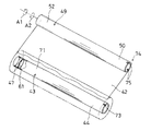
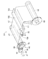
図1は、本発明の実施の一形態のインクフィルムリールを備えるインクフィルム保持装置41を示す断面図であり、図2は第1および第2側板54,55に設けられる第1〜第4支持具46,48,51,53を示す斜視図である。本実施の形態のインクフィルム保持装置41は、インクフィルム42が巻回される供給リール43と、供給リール43の軸線方向一端部44に嵌まり込み、かつ前記軸線まわりの回転に対して制動力が生じる回動部45を有し、前記供給リール43の軸線方向一端部44に着脱自在に装着される第1支持具46と、前記供給リール43の軸線方向他端部47に着脱自在に装着され、供給リール43の軸線方向他端部47を前記軸線まわりに回転自在に支持する第2支持具48と、供給リール43と平行に配置され、供給リール43から導かれたインクフィルム42を巻き取る巻取リール49と、巻取リール49の軸線方向一端部50に着脱自在に装着され、予め定める巻取り方向A1に回転駆動される第3支持具51と、巻取リール49の軸線方向他端部52に着脱自在に装着され、巻取リール49の軸線方向他端部52を前記軸線まわりに回転自在に支持する第4支持具53と、第1および第3支持具46,51を各軸線まわりに回転自在に支持する第1側板54と、第2および第4支持具48,53が固定される第2側板55とを含む。
FIG. 1 is a cross-sectional view showing an ink
前記供給リール43には、軸線方向他端部47の端面60よりも軸線方向一端部44寄りに前記第2支持具48によって回転自在に支持される軸受部61が設けられる。前記第2および第4支持具48,53は、第2側板55の第1側板54と対向する内面から前記第1側板54に近接するにつれて先細状に突出して形成される。
The
第2支持具48の供給リール43の装着完了位置における外径D1と、第4支持具53の巻取リール49の装着完了位置における外径D2とを異ならせ、かつ前記供給リール43の軸線方向他端部47の内径d1と、前記巻取リール49の軸線方向他端部52の内径d2とを、前記供給リール43の装着完了位置における外径D1および前記巻取リール49の装着完了位置における外径D2よりも僅かに大きく形成する。前記第2支持具48の供給リール43の装着完了位置における外径D1は、たとえば15mmに選ばれ、前記第4支持具53の巻取リール49の装着完了位置における外径D2は、たとえば13mmに選ばれる。
The outer diameter D1 of the
また、前記供給リール43の軸線方向他端部47の内径d1および前記巻取リール49の軸線方向他端部52の内径d2は、供給リール43の装着完了位置における第2支持具48の外径D1および巻取リール49の装着完了位置における第4支持具53の外径D2よりも僅かに大きい寸法として、供給リール43の内径d1は、たとえばD1+0.1mmに選ばれ、巻取リール49の内径d2は、たとえばD2+0.1mmに選ばれる。
The inner diameter d1 of the
第1支持具46は、供給リール43の回転に伴って回動する前述の回動部45と、この回動部45に同軸に装着される開閉作動部57と、回動部45を開閉作動部57に弾発的に押し付けて、回動部45の回転時に開閉作動部57から前記回動部45に回転方向とは逆向きに制動力を作用させるバックテンション用ばね58とを有する。このバックテンション用ばね58は、圧縮コイルばねによって実現され、ほぼ一定のばね力で前記回動部45を開閉作動部57に軸線方向に押圧して、そのばね力に応じた制動トルクを回動部45に作用させることができる。
The
回動部45は、供給リール43の軸線方向一端部44に挿入される直円筒状の筒部62と、筒部62の軸線方向一端部に一体的に形成されるフランジ63と、筒部62の前記フランジ63寄りの外周面から半径方向外方に突出する1つの回り止め突起64とを有する。筒部62の外径D3は、第2支持具46の供給リール装着完了位置における外径D1に等しく(D3=D1)、長さL2は、供給リール43の軸線方向他端部47の端面60から軸受部61までの距離L1よりも大きく選ばれ、第1および第2支持具46,48の供給リール43の軸線方向両端部への誤装着を防止している。
The rotating
第2支持具48は、軸線に関して軸対称に90°毎に設けられる複数(本実施の形態では4)の台形状のリブ59を有し、熱可塑性合成樹脂の一体成型によって大略的に四角錐状に形成される。前記第4支持具53もまた、前記第2支持具48と同様に構成され、各軸線は平行である。
The
第3支持具51は、巻取リール49の軸線方向一端部50に挿入される直円筒状の筒部66と、筒部66の軸線方向両端部間の中間部に一体的に形成されるフランジ67と、筒部66の軸線方向一端部に一体的に形成される巻取り用歯車68と、筒部66の前記フランジ63寄りの外周面から半径方向外方に突出し、周方向に間隔をあけて設けられる複数(本実施の形態では2)の回り止め突起69とを有する。筒部66の外径D4は、前記第4支持具53の巻取リール装着完了位置における外径D2に等しく(D4=D2)選ばれ、第3および第4支持具51,53の巻取リール49の軸線方向両端部への誤装着を防止している。
The
図3は、供給リール43および巻取リール49の構成を示す斜視図である。前記供給リール43は、大略的に直円筒状の供給リール本体71と、この供給リール本体71の軸線方向他端部に一体的に設けられる前記軸受部61とを有し、熱可塑性合成樹脂のインジェクション成型品によって実現される。供給リール本体71の軸線方向一端部44には、その端面72から軸線方向他端部47側へ切り込まれた1つの切欠き73が形成される。この切欠き73には、第1支持具46の前記回り止め突起64が嵌まり込み、回動部45の回転を確実に伝達することができるように構成される。
FIG. 3 is a perspective view showing the configuration of the
前記巻取リール49は、大略的に直円筒状であって、熱可塑性合成樹脂のインジェクション成型品または紙巻とも呼ばれる紙形成品によって実現される。巻取リール49の軸線方向一端部50には、その端面74から軸線方向他端部52へ切り込まれた2つの切欠き75が周方向に間隔をあけて形成される。これらの切欠き75には、第3支持具51の2つの回り止め突起69が嵌まり込み、第3支持具51の巻取り方向A1への回転を確実に伝達することができるように構成されている。
The take-
図4は第1支持具46の具体的構成を示す拡大断面図であり、図5は図4の右側から見た第1支持具46の正面図である。第1支持具46は、前述したように回動部45、開閉作動部57およびバックテンション用ばね58を含む。回動部45および開閉作動部57は、熱可塑性樹脂、たとえばポリオキシメチレン(polyoxymethlene;略称POM)などの摺動グレード材のインジェクション成型によって形成される。開閉作動部57は、外周部に複数の歯が形成されたピニオン78と、ピニオン78と同軸に一体成形されるスタッド79とを有する。
4 is an enlarged cross-sectional view showing a specific configuration of the
スタッド79は、一表面にピニオン78が一体に形成されるフランジ78aの他表面から垂直に突出する直円柱状の大径軸部81と、大径軸部81の先端部に同軸に突出する直円柱状の小径軸部82と、小径軸部82の先端部に連なる略T字状のばね受け片83とを有する。小径軸部82と大径軸部81との間には、軸線に垂直な仮想一平面内で円環状の段差面84が形成される。ばね受け片83には、小径軸部82に装着された前記バックテンション用ばね58の一端部が嵌まり込んで係止され、抜け出しが防止されている。
The
このようなスタッド79には、前記回動部45が装着される。回動部45は、前述したように、直円筒状の筒部62と、筒部62の軸線方向一端部に一体的に形成されるフランジ63と、筒部62の前記フランジ63寄りの付け根から突出する回り止め突起64とを有する。筒部62は、その内周面から半径方向内方に突出する円環状の内向きフランジ85を有する。
The rotating
この内向きフランジ85は、筒部62が前記スタッド79に装着された状態において、段差面84よりも遊端側、すなわち図4の右側に配置される。この内向きフランジ85には、前記バックテンション用ばね58の他端部が弾発的に当接して支持され、筒部62はピニオン78に近接する方向にほぼ一定の押圧力で押圧され、これによってフランジ63がピニオン78の円環状の摺動面86に弾発的に押し付けられる。
The
したがって開閉作動部57の回転が阻止された状態で前記回動部45がその軸線まわりに回転すると、回動部45のフランジ63には、摺動面86との摺動摩擦によって、その回転方向とは逆方向に制動トルクが作用し、インクフィルム42にバックテンション(=緊張力)を与え、皺およびたるみの発生を防止することができる。本実施の形態では、インクフィルム42のバックテンションは、一例として述べると、60gf・cm〜250gf・cmに選ばれ、好ましくは160gf・cm±30gf・cmに選ばれる。
Therefore, when the
このようなバックテンションの大きさは、前記バックテンション用ばね58のばね力の選定によって調整することができるが、ピニオン78およびフランジ63の材質または摺動グレードを変更して、摺動面86およびフランジ63の対向表面63aの動摩擦係数を変化させてもよく、さらに両者の接触面積を変化させて、インクフィルム42に最適なバックテンションを作用させるようにしてもよい。
The magnitude of such back tension can be adjusted by selecting the spring force of the
図6はインクフィルム保持装置41が搭載される印刷装置91の簡略化した断面図であり、図7は印刷装置91のインクフィルム検出部92の構成を説明するための簡略化した斜視図である。前述したインクフィルム保持装置41は、ファクシミリ、プリンタおよび複写機などの画像印刷機能を有する通信装置および情報処理装置に搭載されるライン印字式の熱転写型印刷装置などとして実現される印刷装置91に搭載される。
FIG. 6 is a simplified cross-sectional view of the
この印刷装置91は、装置本体94と、基端部に設けられるピン93によってその軸線95まわりに開放方向B1および閉鎖方向B2に角変位自在に連結される係合部材である搖動レバー96を有し、少なくとも前記第1支持具46が収容される領域を含む装置本体94を上方から覆う蓋体97とを備える。
This
前記蓋体97の搖動レバー96は、開閉動作に連動して、開放時に第1支持具46の回動部45を予め定めるインクフィルム繰出し方向A2に回転させ、閉鎖時に第1支持具46の回動部45を前記繰出し方向A2とは逆方向の巻取り方向A1に回転させるラック98が設けられる。このラック98は、第1支持具46のピニオン78に噛合し、ピニオン78の回転が前記摺動面86にバックテンション用ばね58のばね力によって押し当てられたフランジ63を介して筒部62に伝達され、供給リール43を、蓋体97の開放時には繰出し方向A2に回動させてインクフィルム42を弛緩させ、また閉鎖時には巻取り方向A1に回動させてインクフィルム42を緊張させることができる。
The
装置本体94は、本体ケース100を有する。この本体ケース100は、インクフィルム42が巻回される供給リール43が収容される上方に開放した供給リール収容空間101と、インクフィルム42が巻回される巻取リール49が収容される上方に開放した巻取リール収容空間102と、各収容空間101,102間に配置される印字ヘッド103が収容される印字ヘッド収容空間104とを有する。また前記本体ケース100内の内部空間105には、前記インクフィルム検出部92が設けられる。前記蓋体97には、閉鎖時に供給リール43および巻取リール49間に張架されるインクフィルム42を図示しない用紙とともに印字ヘッド103上に適度の接触圧で接触するように押圧する押さえローラ106が設けられる。
The apparatus main body 94 has a
前記インクフィルム検出部92は、本体ケース100の前記印字ヘッド収容空間104と供給リール収容空間101との間で上方に立ち上がる立上がり部107の開口部108からさらに上方に弾発的に突出する検知レバー109を備える。この検知レバー109は、前記立上がり部107上で、装置本体94に設けられるガイドピン110と供給リール43とにわたって張架されるインクフィルム42の張架部分に下方から軽く当接し、この張架部分によって参照符112max,112minで示されるように、最大巻回状態から最小巻回状態にわたって下方へ押し下げられると、スイッチング態様をオンからオフへ、またはオフからオンへ変化させ、蓋体97が閉鎖されてインクフィルム42が緊張したことを検出することができるように構成されている。
The ink
上記のように構成される本実施の形態のインクフィルム保持装置41によれば、前記供給リール43の軸線方向一端部44には第1支持具46が装着され、軸線方向他端部47には第2支持具48が装着される。また、巻取リール49の軸線方向一端部50には第3支持具51が装着され、軸線方向他端部52には第4支持具53が装着される。第1および第3支持具46,51は、第1側板54によって各軸線まわりに回転自在に支持され、第2および第4支持具48,53は第2側板55に固定される。
According to the ink
前記第3支持具51が巻取り方向A1に回転駆動されると、その回転が巻取リール49に伝達され、供給リール43から導かれるインクフィルム42が巻き取られ、このインクフィルム42の張力によって供給リール43が従動して回転する。このとき、第1支持具46の回動部45は、供給リール43に連動して回転するが、この回動部45はその回転に対してバックテンション用ばね58によって制動力が働くように構成されているので、前記供給リール43の回転は制動され、これによって供給リール43および巻取リール49間にわたって張架されるインクフィルム42に張力を発生させて、いわゆるバックテンションを与え、インクフィルム42のインクが用紙に転写される領域におけるインクフィルム42の皺やたるみを防いで、印刷画像のずれおよび乱れなどの印刷不良を防止することができる。
When the
このようなバックテンションは、前記第1支持具46によって実現されるので、この保持装置41が搭載される印刷装置91の装置本体94自体に、前記供給リール43の回転を制動するバックテンション機構を設ける必要がなく、したがって装置本体94内が前記バックテンション機構によって占有されず、装置の小形化を図ることが可能となる。また、インクフィルム42を交換するに際して、第2および第4支持具48,53が第2側板55に固定されるので、第2および第4支持具48,53が個々に分離されている場合に比べて、供給リール43の軸線方向他端部47と第2支持具48との着脱作業および巻取リール49の軸線方向他端部52と第4支持具53との着脱作業が簡素化され、インクフィルム42の交換作業が容易となり、作業性が向上される。
Since such back tension is realized by the
また、供給リール43の前記第2支持具48によって支持される軸線方向他端部47には、この軸線方向他端部47よりも軸線方向一端部44寄りに軸受部61が形成されるので、この軸受部61は供給リール43の軸線方向他端部47の端面60よりも前記軸線方向一端部44寄りに退避しており、したがって第2支持具48が供給リール43の軸線方向他端部47内に嵌まり込んだ状態で、前記供給リール43の軸線方向他端部47が支持される。これによって供給リール43の軸線方向他端部47の端面60と第2支持具48が設けられる第2側板55との間隔を、前記軸受部61が供給リール43の軸線方向他端部47の端面60から軸線方向一端部44寄りに退避した距離ΔL(図1参照)だけ少なくし、第1および第2側板54,55を互いに近接させて、保持装置41の占有空間を減少させ、この保持装置41が搭載される印刷装置91を小形化することができる。
In addition, since the
さらに、第2支持具48は上記のように第1側板54に向かって先細状に形成されるので、供給リール43の軸線方向他端部47を第2支持具48に装着し易く、インクフィルム交換時の供給リール43の装着作業が容易化される。また、第2支持具47が先細状とされることによって、前記軸受部61は第2支持具48の先端部によって支持され、これによって供給リール43の回転軸線を第2支持具48の軸線に一致させて、円滑な供給リール43の回転が得られ、供給リール43から巻取リール49にわたって張架されるインクフィルム42の張力のばらつきを防ぎ、印刷不良の発生を低減することができる。
Further, since the
さらに、第4支持具53が前記第2支持具48と同様に先細状に形成されるので、巻取リール49の軸線方向他端部52を第4支持具53に装着し易く、インクフィルム交換時の巻取リール49の装着作業が容易化される。
Further, since the
さらに、第2支持具48の供給リール43の装着完了位置における外径D1と、第4支持具53の巻取リール49の装着完了位置における外径D2とが異なり、供給リール43の軸線方向他端部47の内径d1と、前記巻取リール49の軸線方向他端部47の内径d2とが、前記供給リール43の装着完了位置における外径D1および前記巻取リール49の装着完了位置における外径D2よりもそれぞれ僅かに大きく形成されるので、供給リール43を第4支持具53に装着しようとし、また巻取リールを49を第2支持具48に装着しようとしても、挿入が不可能であるか、挿入できても遊嵌合状態であるため、作業者に誤装着であること容易に認識させ、供給リール43および巻取リール49の装填ミスを防止することができる。
Further, the outer diameter D1 of the
さらに、上記のように第2および第4支持具48,53は第2側板55に固定されるので、インクフィルム交換時に供給リール43および巻取リール49に対して、第2および第4支持具48,53の着脱作業が省略され、これによってインクフィルム交換時に供給リール43および巻取リール49に対して装着し、または抜き取られる部品点数が少なくて済み、作業が簡素化されて、インクフィルム交換作業の作業性が向上される。
Furthermore, since the second and
さらに、印刷装置91の蓋体97に係合部材であるラック98が設けられるので、インクフィルム交換時に前記蓋体97を開放することによって、第1支持具46の回動部45が繰出し方向A2に回転され、供給リール43および巻取リール49間にわたって張架されるインクフィルム42の張架部分111を弛緩させることができる。また、インクフィルム42の交換が終了して蓋体97を閉鎖すると、第1支持具46の回動部45がラック98によって巻取り方向A1に回転され、供給リール43および巻取リール49間に弛緩状態で張架されるインクフィルム42の張架部分111を緊張させ、次の印刷動作が開始されるに先だって、インクフィルム42の皺やたるみの発生を防止することができる。
Furthermore, since a
本発明の実施の他の形態では、前記供給リール43の軸線方向一端部44の内径d3を軸線方向他端部47の内径d1よりも大きく(d3>d1)し、供給リール43の軸線方向両端部44,47への第1および第2支持具46,48の誤装着を防止するように構成されてもよい。
In another embodiment of the present invention, the inner diameter d3 of the one
本発明の実施のさらに他の形態では、第1側板54に第1および第3支持具46,51が装着され、これらの第1および第3支持具46,51に供給リール43および巻取リール49の各軸線方向一端部44,50を装着してユニット化されてもよい。これによってインクフィルムの交換作業を容易かつ迅速に行うことができる。
In still another embodiment of the present invention, the first and
本発明の実施のさらに他の形態では、上記供給リール43と巻取リール49とが第1および第3支持具46,51を介して第1側板54に取付けられた構成に加えて、第2側板55に固定された第2および第4支持具48,53を供給リール43および巻取リール49の各軸線方向他端部47,52に装着してユニット化されてもよい。これによって、より一層インクフィルムの交換作業を容易かつ迅速に行うことができる。
In still another embodiment of the present invention, in addition to the configuration in which the
本発明は、次の実施の形態が可能である。
(1)インクフィルムが巻回される供給リールと、
前記供給リールの軸線方向一端部に嵌まり込み、かつ前記軸線まわりの回転に対して制動力が生じる回動部を有し、前記供給リールの軸線方向一端部に着脱自在に装着される第1支持具と、
前記供給リールの軸線方向他端部に着脱自在に装着され、前記供給リールの軸線方向他端部を前記軸線まわりに回転自在に支持する第2支持具と、
前記供給リールと平行に配置され、供給リールから導かれたインクフィルムを巻き取る巻取リールと、
前記巻取リールの軸線方向一端部に着脱自在に装着され、予め定める巻取り方向に回転駆動される第3支持具と、
前記巻取リールの軸線方向他端部に着脱自在に装着され、前記巻取リールの軸線方向他端部を前記軸線まわりに回転自在に支持する第4支持具と、
第1および第3支持具を各軸線まわりに回転自在に支持する第1側板と、
第2および第4支持具が固定される第2側板とを含むことを特徴とするインクフィルム保持装置。
The following embodiments are possible for the present invention.
(1) a supply reel on which the ink film is wound;
A first fitting portion that fits into one end portion in the axial direction of the supply reel and that generates a braking force against rotation around the axis, and is detachably attached to one end portion in the axial direction of the supply reel. A support,
A second support that is detachably attached to the other end in the axial direction of the supply reel, and rotatably supports the other end in the axial direction of the supply reel around the axis;
A take-up reel that is arranged in parallel with the supply reel and winds up an ink film guided from the supply reel;
A third support that is detachably attached to one end of the take-up reel in the axial direction and is driven to rotate in a predetermined take-up direction;
A fourth support that is detachably attached to the other end in the axial direction of the take-up reel, and that rotatably supports the other end in the axial direction of the take-up reel;
A first side plate that rotatably supports the first and third support members about each axis;
And a second side plate to which the second and fourth support members are fixed.
このような構成によれば、第1および第2側板間には、供給リールと巻取リールとが平行に配置され、供給リールに巻回されたインクフィルムは、巻取リールに巻き取られて回収され、第1および第2側板に対して、新しいインクフィルムが巻回された新たな供給リールおよびインクフィルムが巻回されていない新たな巻取リールに交換される。 According to such a configuration, the supply reel and the take-up reel are arranged in parallel between the first and second side plates, and the ink film wound around the supply reel is taken up and collected by the take-up reel. Then, the first and second side plates are replaced with a new supply reel on which a new ink film is wound and a new take-up reel on which no ink film is wound.
このようなインクフィルム保持装置において、前記供給リールの軸線方向一端部には第1支持具が装着され、軸線方向他端部には第2支持具が装着される。また、巻取リールの軸線方向一端部には第3支持具が装着され、軸線方向他端部には第4支持具が装着される。第1および第3支持具は、第1側板によって各軸線まわりに回転自在に支持され、第2および第4支持具は第2側板に固定される。 In such an ink film holding device, a first support is attached to one end of the supply reel in the axial direction, and a second support is attached to the other end in the axial direction. A third support is attached to one end in the axial direction of the take-up reel, and a fourth support is attached to the other end in the axial direction. The first and third support tools are supported by the first side plate so as to be rotatable about each axis, and the second and fourth support tools are fixed to the second side plate.
したがって供給リールの軸線まわりの回転は、軸線方向一端部に装着された第1支持具が第1側板によって回転自在に支持され、軸線方向他端部が第2支持具によって回転自在に支持されることによって、許容される。また、巻取リールの軸線まわりの回転は、軸線方向一端部に装着された第3支持具が第1側板によって回転自在に支持され、軸線方向他端部が第4支持具によって回転自在に支持されることによって、許容される。 Accordingly, the rotation of the supply reel around the axis is such that the first support attached to one end in the axial direction is rotatably supported by the first side plate, and the other end in the axial direction is rotatably supported by the second support. Is acceptable. In addition, the rotation of the take-up reel around the axis is supported by the first support plate rotatably on the third support attached to one end in the axial direction, and the other end of the take-up reel is supported rotatably by the fourth support. Is allowed.
前記第3支持具が予め定める巻取り方向に回転駆動されると、その回転が巻取リールに伝達され、供給リールから導かれるインクフィルムが巻き取られ、このインクフィルムの張力によって供給リールが従動して回転する。このとき、第1支持具の回動部は、供給リールに連動して回転するが、この回動部は回転に対して制動力が働くように構成されているので、前記供給リールの回転は制動され、これによって供給リールおよび巻取リール間にわたって張架されるインクフィルムに張力を発生させて、いわゆるバックテンションを与え、インクフィルムのインクが用紙に転写される領域におけるインクフィルムの皺やたるみを防いで、印刷画像のずれおよび乱れなどの印刷不良を防止することができる。 When the third support is rotated in a predetermined winding direction, the rotation is transmitted to the take-up reel, the ink film guided from the supply reel is taken up, and the supply reel is driven by the tension of the ink film. Rotate. At this time, the rotating portion of the first support member rotates in conjunction with the supply reel. Since the rotating portion is configured to act as a braking force against the rotation, the rotation of the supply reel is performed. The tension is applied to the ink film stretched between the supply reel and the take-up reel, thereby applying a so-called back tension to prevent the ink film from wrinkling and sagging in the area where the ink of the ink film is transferred to the paper. It is possible to prevent printing defects such as misalignment and disorder of the printed image.
このようなバックテンションをインクフィルムに与えるための供給リールの回転に対する制動は、前記第1支持具によって実現されるので、この保持装置が搭載される装置の装置本体に、前記供給リールの回転を制動するバックテンション機構を設ける必要がなく、したがって装置本体内が前記バックテンション機構によって占有されず、装置の小形化を図ることが可能となる。また、インクフィルムを交換するに際して、第2および第4支持具が第2側板に固定されるので、第2および第4支持具が個々に分離されている場合に比べて、供給リールの軸線方向他端部と第2支持具との着脱作業および巻取リールの軸線方向他端部と第4支持具との着脱作業が簡素化され、インクフィルム交換時の作業が容易となり、作業性が向上される。 Since the braking against the rotation of the supply reel for applying the back tension to the ink film is realized by the first support, the rotation of the supply reel is braked on the apparatus main body of the apparatus on which the holding device is mounted. Therefore, there is no need to provide a back tension mechanism, so that the interior of the apparatus is not occupied by the back tension mechanism, and the apparatus can be miniaturized. Further, when the ink film is replaced, the second and fourth support members are fixed to the second side plate, so that the axial direction of the supply reel and the like are different from those in the case where the second and fourth support members are individually separated. The attachment / detachment operation between the end portion and the second support member and the attachment / detachment operation between the other end portion in the axial direction of the take-up reel and the fourth support member are simplified, the operation at the time of ink film replacement is facilitated, and the workability is improved. .
(2)前記供給リールには、軸線方向他端部よりも軸線方向一端部寄りに前記第2支持具によって回転自在に支持される軸受部が設けられることを特徴とするインクフィルム保持装置。 (2) The ink film holding device, wherein the supply reel is provided with a bearing portion rotatably supported by the second support tool closer to one end in the axial direction than the other end in the axial direction.
このような構成によれば、供給リールの前記第2支持具によって支持される軸線方向他端部には、この軸線方向他端部よりも軸線方向一端部寄りに軸受部が形成されるので、この軸受部は供給リールの軸線方向他端部の端面よりも前記軸線方向一端部寄りに退避しており、したがって第2支持具が供給リールの軸線方向他端部内に嵌まり込んだ状態で、前記供給リールの軸線方向他端部が支持される。これによって供給リールの軸線方向他端部の端面と第2支持具が設けられる第2側板との間隔を、前記軸受部が供給リールの軸線方向他端部の端面から軸線方向一端部寄りに退避した距離だけ少なくし、第2支持具が設けられる第2側板を第1側板寄りに近接させて、保持装置の占有空間を減少させ、この保持装置が搭載される装置を小形化することができる。 According to such a configuration, a bearing portion is formed closer to one end in the axial direction than the other end in the axial direction at the other end in the axial direction supported by the second support of the supply reel. The bearing portion is retracted closer to the one end in the axial direction than the end surface of the other end in the axial direction of the supply reel, and thus the second support is fitted in the other end in the axial direction of the supply reel. The other end of the supply reel in the axial direction is supported. As a result, the interval between the end surface of the other end in the axial direction of the supply reel and the second side plate on which the second support is provided is retracted from the end surface of the other end in the axial direction of the supply reel toward the one end in the axial direction. The second side plate provided with the second support is made closer to the first side plate to reduce the occupied space of the holding device, and the device on which the holding device is mounted can be reduced in size. .
(3)第2支持具は、第2側板から突出するにつれて先細状に形成されることを特徴とするインクフィルム保持装置。 (3) The ink film holding device, wherein the second support is formed in a tapered shape as it protrudes from the second side plate.
このような構成によれば、第2支持具が先細状に形成されるので、供給リールの軸線方向他端部を第2支持具に装着し易く、インクフィルム交換時の供給リールの装着作業が容易化される。また、第2支持具が先細状とされることによって、前記軸受部は第2支持具の先端部によって支持され、これによって供給リールの回転軸線を第2支持具の軸線に一致させて、円滑な供給リールの回転が得られ、供給リールから巻取リールにわたって張架されるインクフィルムの張力のばらつきを防ぎ、印刷不良の発生を低減することができる。 According to such a configuration, since the second support tool is formed in a tapered shape, it is easy to attach the other axial end of the supply reel to the second support tool, and it is easy to attach the supply reel when replacing the ink film. It becomes. Further, since the second support tool is tapered, the bearing portion is supported by the tip end portion of the second support tool, and thereby the rotation axis of the supply reel is made to coincide with the axis of the second support tool, thereby smoothly Thus, the rotation of the supply reel can be obtained, variation in the tension of the ink film stretched from the supply reel to the take-up reel can be prevented, and the occurrence of printing defects can be reduced.
(4)第4支持具は、第2側板から突出するにつれて先細状に形成されることを特徴とするインクフィルム保持装置。 (4) The ink film holding device, wherein the fourth support is formed in a tapered shape as it protrudes from the second side plate.
このような構成によれば、第4支持具が先細状に形成されるので、巻取リールの軸線方向他端部を第4支持具に装着し易く、インクフィルム交換時の巻取リールの装着作業が容易化される。 According to such a configuration, since the fourth support tool is formed in a tapered shape, the other end in the axial direction of the take-up reel can be easily attached to the fourth support tool, and the take-up reel is attached when the ink film is replaced. Is facilitated.
(5)第2支持具の供給リールの装着完了位置における外径と、第4支持具の巻取リールの装着完了位置における外径とを異ならせ、かつ前記供給リールの軸線方向他端部の内径と、前記巻取リールの軸線方向他端部の内径とを、前記供給リールの装着完了位置における外径および前記巻取リールの装着完了位置における外径よりも僅かに大きく形成したことを特徴とするインクフィルム保持装置。 (5) The outer diameter of the supply reel of the second support tool at the mounting completion position is different from the outer diameter of the fourth support tool at the mounting completion position of the take-up reel, and the other end of the supply reel in the axial direction is different. The inner diameter and the inner diameter of the other end in the axial direction of the take-up reel are formed to be slightly larger than the outer diameter at the supply reel installation completion position and the outer diameter at the take-up reel installation completion position. Ink film holding device.
このような構成によれば、第2支持具の供給リールの装着完了位置における外径と、第4支持具の巻取リールの装着完了位置における外径とが異なり、供給リールの軸線方向他端部の内径と、前記巻取リールの軸線方向他端部の内径とが、前記供給リールの装着完了位置における外径および前記巻取リールの装着完了位置における外径よりも僅かに大きく形成されるので、供給リールを第4支持具に装着しようとし、または巻取リールを第2支持具に装着しようとしても、挿入が不可能であるか、挿入できても遊嵌合状態であるため、作業者に誤装着であること容易に認識させ、供給リールおよび巻取リールの装填ミスを防止することができる。 According to such a configuration, the outer diameter of the supply reel of the second support tool at the mounting completion position is different from the outer diameter of the fourth support tool at the mounting completion position of the take-up reel. And the inner diameter of the other end in the axial direction of the take-up reel are formed slightly larger than the outer diameter at the supply reel installation completion position and the outer diameter at the take-up reel installation completion position. Therefore, even if an attempt is made to attach the supply reel to the fourth support member or an attempt to attach the take-up reel to the second support member, the insertion is impossible, or even if it can be inserted, it is in a loosely fitted state. It is possible to easily recognize that it is erroneously installed by a person and to prevent a mistake in loading the supply reel and the take-up reel.
(6)第2側板は、前記インクフィルムを用いて印刷する装置の装置本体に固定されていることを特徴とするインクフィルム保持装置。 (6) The ink film holding device, wherein the second side plate is fixed to a device body of a device that prints using the ink film.
このような構成によれば、インクフィルム交換時に供給リールおよび巻取リールに対して、第2および第4支持具の着脱作業が省略され、これによってインクフィルム交換時に供給リールおよび巻取リールに対して装着し、または抜き取られる部品点数が少なくて済み、作業が簡素化されて、インクフィルム交換作業の作業性が向上される。 According to such a configuration, the work for attaching and detaching the second and fourth supports to the supply reel and the take-up reel when the ink film is replaced is omitted, and thus the attachment to the supply reel and the take-up reel is performed when the ink film is replaced. However, the number of parts to be extracted can be reduced, the operation is simplified, and the workability of the ink film replacement operation is improved.
(7)前記装置本体には、少なくとも前記第1支持具が収容される領域を覆う蓋体が開閉自在に設けられ、この蓋体には、蓋体の開閉動作に連動して、開放時に第1支持具の回動部を予め定めるインクフィルム繰出し方向に回転させ、閉鎖時に第1支持具の回動部を前記予め定める巻取り方向に回転させる係合部材が設けられることを特徴とするインクフィルム保持装置。 (7) The device main body is provided with a lid that covers at least an area in which the first support is accommodated, and the lid can be opened and closed in conjunction with the opening and closing operation of the lid. An ink film holding device comprising: an engaging member that rotates a rotating portion of one support tool in a predetermined ink film feeding direction and rotates the rotating portion of the first support device in the predetermined winding direction when closed. apparatus.
このような構成によれば、蓋体に係合部材が設けられるので、インクフィルムの交換時に前記蓋体を開放することによって、第1支持具の回動部が係合部材によって繰出し方向に回転され、供給リールおよび巻取リール間にわたって張架されるインクフィルムを弛緩させることができる。また、インクフィルムの交換が終了して蓋体を閉鎖すると、第1支持部の回動部が係合部材によって巻取り方向に回転され、供給リールおよび巻取リール間に弛緩状態で張架されるインクフィルムを緊張させ、次の印刷動作が開始されるに先だって、インクフィルムの皺やたるみの発生を防止することができる。 According to such a configuration, since the engaging member is provided on the lid, the rotating portion of the first support member is rotated in the feeding direction by the engaging member by opening the lid when replacing the ink film. The ink film stretched between the supply reel and the take-up reel can be relaxed. When the replacement of the ink film is completed and the lid is closed, the rotating portion of the first support portion is rotated in the winding direction by the engaging member, and is stretched between the supply reel and the winding reel in a relaxed state. Prior to starting the next printing operation by tensioning the ink film, it is possible to prevent wrinkling and sagging of the ink film.
(8)供給リールは、その軸線方向一端部の内径が、軸線方向他端部の内径よりも大きく選ばれていることを特徴とするインクフィルム保持装置。 (8) The ink film holding device, wherein the supply reel has an inner diameter at one end in the axial direction larger than an inner diameter at the other end in the axial direction.
このような構成によれば、供給リールの軸線方向一端部の内径が軸線方向他端部の内径よりも大きく形成されるので、第1支持具を供給リールの軸線方向他端部に装着することが不可能であり、これによって誤装着が防がれる。 According to such a configuration, the inner diameter of one end of the supply reel in the axial direction is formed larger than the inner diameter of the other end in the axial direction. Therefore, the first support is attached to the other end in the axial direction of the supply reel. Is impossible, and this prevents mis-installation.
(9)前記供給リールと巻取リールとは、少なくとも第1側板に第1および第3支持具ととも装着されてユニット化されていることを特徴とするインクフィルム保持装置。 (9) The ink film holding device, wherein the supply reel and the take-up reel are unitized by being attached to at least the first side plate together with the first and third supports.
このような構成によれば、第1側板に第1および第3支持具によって供給リールと巻取リールとを装着してユニット化されるので、インクフィルムの交換を容易かつ迅速に行うことができる。 According to such a configuration, since the supply reel and the take-up reel are mounted on the first side plate by the first and third supports to form a unit, the ink film can be replaced easily and quickly.
(10)インクフィルムが巻回される直円筒状のリール本体を有し、このリール本体の軸線方向両端部が、前記インクフィルムを用いて印刷する装置の装置本体に、支持具によって前記軸線まわりに回転自在に支持されるインクフィルムリールにおいて、
前記リール本体の軸線方向一端部には、その軸線方向一端部の端面よりも軸線方向他端部寄りに退避して、前記支持具の先端部によって前記軸線まわりに回転自在に支持される軸受部が設けられることを特徴とするインクフィルムリール。
(10) It has a right cylindrical reel body around which an ink film is wound, and both end portions in the axial direction of the reel body are rotated around the axis line by a support tool on the apparatus body of the apparatus for printing using the ink film. In an ink film reel that is freely supported,
A bearing portion that is retracted closer to the other end in the axial direction than the end face of the one end in the axial direction is supported at the one end in the axial direction of the reel body and is rotatably supported around the axis by the tip end of the support An ink film reel comprising:
このような構成によれば、インクフィルムリールの支持具によって支持される軸線方向他端部には、この軸線方向他端部よりも軸線方向一端部寄りに軸受部が形成されるので、この軸受部はインクリールフィルムリールの軸線方向他端部の端面よりも前記軸線方向一端部寄りに退避しており、したがって支持具がインクフィルムリールの軸線方向他端部内に嵌まり込んだ状態で、インクフィルムリールの軸線方向他端部が支持される。これによってインクフィルムリールの軸線方向他端部の端面と支持具が設けられる側板との間隔を、前記軸受部がインクフィルムリールの軸線方向他端部の端面から軸線方向一端部寄りに退避した距離だけ少なくし、支持具が設けられる各側板に相互に近接させて、保持装置の占有空間を減少させ、この保持装置が搭載される装置を小形化することができる。 According to such a configuration, a bearing portion is formed closer to one end in the axial direction than the other end in the axial direction at the other end in the axial direction supported by the support for the ink film reel. Is retracted closer to one end in the axial direction than the end surface of the other end in the axial direction of the ink reel film reel, and therefore the support of the ink film reel is fitted into the other end in the axial direction of the ink film reel. The other axial end is supported. As a result, the distance between the end surface of the other end in the axial direction of the ink film reel and the side plate on which the support is provided is reduced by the distance that the bearing is retracted from the end surface of the other end in the axial direction of the ink film reel toward one end in the axial direction. In addition, it is possible to reduce the space occupied by the holding device by making the side plates provided close to each other close to each other, thereby reducing the size of the device on which the holding device is mounted.
(11)熱可塑性合成樹脂から成ることを特徴とするインクフィルムリール。
このような構成によれば、前記インクフィルムリールが熱可塑性合成樹脂から成るので、インクフィルムが使用された交換後のインクフィルムリールを再利用することができ、経済性が向上される。
(11) An ink film reel comprising a thermoplastic synthetic resin.
According to such a configuration, since the ink film reel is made of the thermoplastic synthetic resin, the replaced ink film reel in which the ink film is used can be reused, and the economy is improved.
41 インクフィルム保持装置
42 インクフィルム
43 供給リール43
44 供給リール43の軸線方向一端部
45 回動部
46 第1支持具
47 供給リール43の軸線方向他端部
48 第2支持具
49 巻取リール
50 巻取リール49の軸線方向一端部
51 第3支持具
52 巻取リール49の軸線方向他端部
53 第4支持具
54 第1側板
55 第2側板
57 開閉作動部
58 バックテンション用ばね
61 軸受部
64,69 回り止め突起
78 ピニオン
86 摺動面
91 印刷装置
94 装置本体
97 蓋体
98 ラック
41 Ink
44 One end portion in the axial direction of the
Claims (12)
前記リール本体の軸線方向他端部には、その軸線方向他端部の端面よりも軸線方向一端部寄りに退避して前記リール本体内に設けられ、前記支持具の先端部によって前記軸線まわりに回転自在に前記リール本体を支持するための軸受部を備えたことを特徴とするインクフィルムリール。 A reel body having a right cylindrical shape around which an ink film is wound is provided, and both end portions in the axial direction of the reel body are supported by an apparatus body for printing using the ink film so as to be rotatable around the axis by a support tool. In the ink film reel,
The other end portion in the axial direction of the reel body is provided in the reel body by being retracted closer to the one end portion in the axial direction than the end face of the other end portion in the axial direction. An ink film reel comprising a bearing portion for rotatably supporting the reel body.
前記供給リールには、その軸線方向他端部の端面よりも軸線方向一端部寄りに退避して軸受部が設けられ、この軸受部が前記支持具の先端部によって前記軸線まわりに回転自在に支持されることを特徴とするインクフィルムリール。 An apparatus main body including a supply reel on which an ink film is wound and a take-up reel that winds up the ink film supplied from the supply reel, wherein both end portions in the axial direction of the take-up reel and the supply reel are printed using the ink film In addition, in each of the ink film reels that are rotatably supported around the axis by a support tool,
The supply reel is provided with a bearing portion retracted closer to one end in the axial direction than the end face of the other end in the axial direction, and the bearing is supported rotatably around the axis by the tip of the support. An ink film reel characterized by being made.
Priority Applications (1)
| Application Number | Priority Date | Filing Date | Title |
|---|---|---|---|
| JP2007046131A JP2007176183A (en) | 2007-02-26 | 2007-02-26 | Ink film reel and ink film securing device |
Applications Claiming Priority (1)
| Application Number | Priority Date | Filing Date | Title |
|---|---|---|---|
| JP2007046131A JP2007176183A (en) | 2007-02-26 | 2007-02-26 | Ink film reel and ink film securing device |
Related Parent Applications (1)
| Application Number | Title | Priority Date | Filing Date |
|---|---|---|---|
| JP2005248462A Division JP4441459B2 (en) | 2005-08-29 | 2005-08-29 | Ink film holding device |
Publications (1)
| Publication Number | Publication Date |
|---|---|
| JP2007176183A true JP2007176183A (en) | 2007-07-12 |
Family
ID=38301802
Family Applications (1)
| Application Number | Title | Priority Date | Filing Date |
|---|---|---|---|
| JP2007046131A Pending JP2007176183A (en) | 2007-02-26 | 2007-02-26 | Ink film reel and ink film securing device |
Country Status (1)
| Country | Link |
|---|---|
| JP (1) | JP2007176183A (en) |
Cited By (1)
| Publication number | Priority date | Publication date | Assignee | Title |
|---|---|---|---|---|
| JP2021049718A (en) * | 2019-09-25 | 2021-04-01 | 大日本印刷株式会社 | Assembly of ribbon cassette, ribbon cassette, and transfer system |
-
2007
- 2007-02-26 JP JP2007046131A patent/JP2007176183A/en active Pending
Cited By (2)
| Publication number | Priority date | Publication date | Assignee | Title |
|---|---|---|---|---|
| JP2021049718A (en) * | 2019-09-25 | 2021-04-01 | 大日本印刷株式会社 | Assembly of ribbon cassette, ribbon cassette, and transfer system |
| JP7340158B2 (en) | 2019-09-25 | 2023-09-07 | 大日本印刷株式会社 | Ribbon cassette assembly and transfer system |
Similar Documents
| Publication | Publication Date | Title |
|---|---|---|
| US7128483B2 (en) | Ribbon cassette with ink ribbon slack prevention mechanism | |
| JP3764360B2 (en) | Ink film holding device | |
| KR101380695B1 (en) | Coating film transfer tool | |
| US7258501B2 (en) | Ink ribbon cartridge | |
| JP7619405B2 (en) | Printing device | |
| JP2597864Y2 (en) | Winding mechanism for band | |
| CN115972790A (en) | Carbon ribbon box structure | |
| JP2007176183A (en) | Ink film reel and ink film securing device | |
| JP4441459B2 (en) | Ink film holding device | |
| JP5183412B2 (en) | Reel equipment | |
| JP3694331B2 (en) | Ink ribbon cassette device in thermal transfer printer | |
| JP2007001101A (en) | Transfer implement | |
| JP2006193322A (en) | Paper feeding device | |
| JP2008137225A (en) | Printer | |
| JP2011207194A (en) | Ink ribbon cassette device in printer, ink ribbon cassette for printer, and printer for ink ribbon cassette | |
| JPH08267861A (en) | Recording apparatus | |
| JP4632969B2 (en) | Ribbon take-up reel | |
| JP2005199468A (en) | Back tension mechanism | |
| JP2017132611A (en) | Roll sheet feeding mechanism and printer | |
| JP2005206312A (en) | Paper feeder and printing device | |
| JPH11157192A (en) | Ribbon cassette for thermal transfer printer | |
| JPH0726122Y2 (en) | Transfer paper and recording paper storage cartridge | |
| JP6557037B2 (en) | Branch holding mechanism and printer | |
| JPH02208080A (en) | Ink ribbon loading device | |
| JP2009006664A (en) | Ink ribbon set |