JP2007176103A - Liquid jetting apparatus, liquid jetting attached device, and liquid jetting system - Google Patents

Liquid jetting apparatus, liquid jetting attached device, and liquid jetting system Download PDF

Info

Publication number
JP2007176103A
JP2007176103A JP2005379933A JP2005379933A JP2007176103A JP 2007176103 A JP2007176103 A JP 2007176103A JP 2005379933 A JP2005379933 A JP 2005379933A JP 2005379933 A JP2005379933 A JP 2005379933A JP 2007176103 A JP2007176103 A JP 2007176103A
Authority
JP
Japan
Prior art keywords
liquid
ink
supply
rechargeable battery
amount
Prior art date
Legal status (The legal status is an assumption and is not a legal conclusion. Google has not performed a legal analysis and makes no representation as to the accuracy of the status listed.)
Pending
Application number
JP2005379933A
Other languages
Japanese (ja)
Inventor
Hiroshi Toyama
央 外山
Current Assignee (The listed assignees may be inaccurate. Google has not performed a legal analysis and makes no representation or warranty as to the accuracy of the list.)
Seiko Epson Corp
Original Assignee
Seiko Epson Corp
Priority date (The priority date is an assumption and is not a legal conclusion. Google has not performed a legal analysis and makes no representation as to the accuracy of the date listed.)
Filing date
Publication date
Application filed by Seiko Epson Corp filed Critical Seiko Epson Corp
Priority to JP2005379933A priority Critical patent/JP2007176103A/en
Publication of JP2007176103A publication Critical patent/JP2007176103A/en
Pending legal-status Critical Current

Links

Images

Abstract

<P>PROBLEM TO BE SOLVED: To provide a liquid jetting apparatus, which has a rechargeable battery, is excellent in portability, and is capable of suppressing waste of stored liquid, a liquid jetting attached device used in combination with the liquid jetting apparatus, and a liquid jetting system having them. <P>SOLUTION: An ink-jet-type printer 12 has, in a main body case 15: a sub ink tank 27 for containing ink; a recording head 25 for jetting the ink; an ink-supply-side connection part 28 for connecting an ink supplying device 13, which supplies ink to the sub ink tank 27, from outside of the main body case 15; a charging-side connection terminal 83 for connecting a charging connection terminal 85 of a charging device, which has the function of charging the rechargeable battery 36 from outside the main body case 15; and a control unit 82 for controlling the amount of electric power for charging the rechargeable battery 36 and the amount of the ink supplied to the sub ink tank 27. The control unit 82 makes control so that the rechargeable battery 36 is charged with the amount of electric power that is necessary for jetting the ink supplied to the sub ink tank 27. <P>COPYRIGHT: (C)2007,JPO&INPIT

Description

本発明は、例えばインクジェット式プリンタ等の液体噴射装置、該液体噴射装置と組み合わせ使用される液体噴射付属装置、及びこれらを備えた液体噴射システムに関する。   The present invention relates to a liquid ejecting apparatus such as an ink jet printer, a liquid ejecting auxiliary apparatus used in combination with the liquid ejecting apparatus, and a liquid ejecting system including these.

従来から、ターゲットに対して液体を噴射する液体噴射装置として、インクジェット式プリンタ(以下、「プリンタ」という。)が知られている。このプリンタは、インクを収容するインクカートリッジと、キャリッジに搭載され、インクカートリッジからインク供給路を介してインク(液体)が供給される記録ヘッド(液体噴射ヘッド)とを備えている。このようなプリンタの中には、加圧ポンプから圧送される加圧空気によりインクカートリッジ内のインクパックを加圧し、インク供給路を介してインクを記録ヘッド側に圧送して、記録ヘッドのノズルから記録媒体に向けてインクを噴射することで印刷を行う、いわゆるオフキャリッジタイプのものがある(例えば、特許文献1)。   Conventionally, an ink jet printer (hereinafter referred to as “printer”) is known as a liquid ejecting apparatus that ejects liquid onto a target. This printer includes an ink cartridge that stores ink, and a recording head (liquid ejecting head) that is mounted on a carriage and is supplied with ink (liquid) from the ink cartridge via an ink supply path. In such a printer, the ink pack in the ink cartridge is pressurized with pressurized air fed from a pressure pump, and the ink is pressure-fed to the recording head side through the ink supply path, and the nozzle of the recording head There is a so-called off-carriage type in which printing is performed by ejecting ink toward a recording medium (for example, Patent Document 1).

ところで、近年、こうしたプリンタでは、携帯性向上の要求が高まってきているため、今まで以上に小型化が進められる傾向にあり、具体的には、持ち運びに便利な携帯用の小型プリンタである、いわゆるモバイルプリンタが知られている。そして、このようなモバイルプリンタの多くは、充電池を内蔵し、該充電池に蓄えられた電力によって印刷を行うようにしている。
特開2005−95861号公報
By the way, in recent years, the demand for improving portability of such printers has been increasing, and thus there is a tendency for further miniaturization more than ever. Specifically, the printer is a portable small printer that is convenient to carry. A so-called mobile printer is known. Many of such mobile printers have a built-in rechargeable battery and perform printing by using the electric power stored in the rechargeable battery.
JP 200595861 A

しかしながら、この場合、充電池に蓄えられる電力には限りがあるため、該充電池に蓄えられた分の電力で印刷することができるインク量よりも多い量のインクがこのモバイルプリンタに備えられていた場合には、この多い分だけのインクが余るため、該インクの無駄が生じてしまう。   However, in this case, since the power stored in the rechargeable battery is limited, the mobile printer is provided with a larger amount of ink than can be printed with the power stored in the rechargeable battery. In such a case, since the ink corresponding to this large amount is left, the ink is wasted.

本発明は、このような従来技術に存在する問題点に着目してなされたものである。その目的とするところは、充電池を備えて携帯性に優れるとともに貯留液体の無駄を抑制することができる液体噴射装置、該液体噴射装置と組み合わせ使用される液体噴射付属装置、及びこれらを備えた液体噴射システムを提供することにある。   The present invention has been made paying attention to such problems existing in the prior art. The object is to provide a liquid ejecting apparatus that is equipped with a rechargeable battery and is excellent in portability and can suppress waste of stored liquid, a liquid ejecting accessory apparatus that is used in combination with the liquid ejecting apparatus, and these It is to provide a liquid ejection system.

上記目的を達成するために、本発明の液体噴射装置は、装置本体内に、液体を貯留する噴射液体貯留部と、前記液体を噴射する液体噴射ヘッドと、前記装置本体外から前記噴射液体貯留部に対して前記液体を供給する機能を有する液体供給装置における液体供給用接続口を着脱自在に接続するための液体供給側接続部と、前記液体を噴射させるための電力を蓄える充電池と、前記装置本体外から前記充電池を充電する機能を有する充電装置における充電用接続口を着脱自在に接続するための充電側接続部と、前記充電池に充電される電力量及び前記噴射液体貯留部に供給される前記液体の供給量を制御する制御手段とを備え、該制御手段は、前記充電池への充電及び前記噴射液体貯留部への前記液体の供給が行われる場合に、前記充電池に充電される電力量が前記噴射液体貯留部に供給される液体供給量に相当する液体を噴射するために必要な電力量となるように、前記充電池に充電される電力量及び前記噴射液体貯留部に供給される前記液体の供給量を制御する。   In order to achieve the above object, a liquid ejecting apparatus according to an aspect of the invention includes an ejecting liquid storing unit that stores liquid in the apparatus main body, a liquid ejecting head that ejects the liquid, and the ejected liquid storing from outside the apparatus main body. A liquid supply side connection part for detachably connecting a liquid supply connection port in a liquid supply apparatus having a function of supplying the liquid to the part, a rechargeable battery for storing electric power for ejecting the liquid, and A charging-side connecting portion for detachably connecting a charging connection port in a charging device having a function of charging the rechargeable battery from outside the device main body, an amount of power charged in the rechargeable battery, and the jet liquid storage portion Control means for controlling the supply amount of the liquid supplied to the rechargeable battery when the charge to the rechargeable battery and the supply of the liquid to the jet liquid storage section are performed. To The amount of power charged in the rechargeable battery and the jet liquid storage unit so that the amount of electric power to be used is the amount of power necessary for jetting the liquid corresponding to the amount of liquid supplied to the jet liquid storage unit The supply amount of the liquid supplied to is controlled.

この発明によれば、液体を噴射して充電池の電力を液体の噴射ができない程度にまで使い切った場合、噴射液体貯留部内には液体が残存しないことになるため、貯留液体の無駄を抑制することが可能となる。加えて、噴射液体貯留部に対して液体を供給する機能及び充電池を充電する機構を装置本体内に有していないため、装置本体を小さくすることが容易になり、充電池を備えて携帯性に優れた液体噴射装置を提供することが可能となる。   According to the present invention, when the liquid is ejected and the power of the rechargeable battery is used up to such an extent that the liquid cannot be ejected, the liquid does not remain in the ejected liquid storage unit, so that waste of stored liquid is suppressed. It becomes possible. In addition, since the apparatus main body does not have a function for supplying liquid to the jet liquid storage section and a mechanism for charging the rechargeable battery, it is easy to make the apparatus main body small, and it is portable with a rechargeable battery. It is possible to provide a liquid ejecting apparatus having excellent properties.

本発明の液体噴射装置は、前記装置本体内には、前記充電池が充電される時間を計測する充電時間計測手段が備えられ、該時間計測手段による計測結果に基づいて、前記制御手段は、前記噴射液体貯留部に供給される前記液体の供給量を制御する。   In the liquid ejecting apparatus according to the aspect of the invention, a charging time measuring unit that measures a time during which the rechargeable battery is charged is provided in the apparatus main body, and based on a measurement result by the time measuring unit, the control unit includes: The supply amount of the liquid supplied to the jet liquid storage unit is controlled.

この発明によれば、充電時間に応じて液体の供給量を制御するため、充電池に充電される電力量を、噴射液体貯留部に供給される液体供給量に相当する液体を噴射するために必要な電力量に確実に合わせることが可能となる。   According to this invention, in order to control the supply amount of the liquid according to the charging time, the amount of power charged in the rechargeable battery is used to eject the liquid corresponding to the liquid supply amount supplied to the ejection liquid storage unit. It is possible to reliably match the required amount of power.

本発明の液体噴射装置は、前記装置本体内には、前記充電池に充電される電力量を計測する電力量計測手段が備えられ、該電力量計測手段による計測結果に基づいて、前記制御手段は、前記噴射液体貯留部に供給される前記液体の供給量を制御する。   In the liquid ejecting apparatus according to the aspect of the invention, a power amount measuring unit that measures the amount of power charged in the rechargeable battery is provided in the device main body, and the control unit is based on a measurement result by the power amount measuring unit. Controls the supply amount of the liquid supplied to the jetting liquid reservoir.

この発明によれば、充電量に応じて液体の供給量を制御するため、充電池に充電される電力量を、噴射液体貯留部に供給される液体供給量に相当する液体を噴射するために必要な電力量に確実に合わせることが可能となる。   According to this invention, in order to control the supply amount of the liquid according to the charge amount, the amount of power charged in the rechargeable battery is used to eject the liquid corresponding to the liquid supply amount supplied to the ejection liquid storage unit. It is possible to reliably match the required amount of power.

本発明の液体噴射装置は、前記装置本体内には、前記噴射液体貯留部に供給される前記液体の供給量を計測する供給量計測手段が備えられ、該供給量計測手段による計測結果に基づいて、前記制御手段は、前記充電池に充電させる電力量を制御する。   In the liquid ejecting apparatus according to the aspect of the invention, a supply amount measuring unit that measures the supply amount of the liquid supplied to the ejected liquid storage unit is provided in the device main body, and based on a measurement result by the supply amount measuring unit. The control means controls the amount of power to be charged in the rechargeable battery.

この発明によれば、液体の供給量に応じて充電量を制御するため、充電池に充電される電力量を、噴射液体貯留部に供給される液体供給量に相当する液体を噴射するために必要な電力量に確実に合わせることが可能となる。   According to this invention, in order to control the charge amount according to the supply amount of the liquid, in order to eject the liquid corresponding to the liquid supply amount supplied to the ejection liquid storage unit, the amount of power charged in the rechargeable battery It is possible to reliably match the required amount of power.

本発明の液体噴射装置は、前記装置本体内には、前記噴射液体貯留部に供給される前記液体の供給時間を計測する供給時間計測手段が備えられ、該供給時間計測手段による計測結果に基づいて、前記制御手段は、前記充電池に充電させる電力量を制御する。   In the liquid ejecting apparatus according to the aspect of the invention, a supply time measuring unit that measures a supply time of the liquid supplied to the ejected liquid storage unit is provided in the apparatus main body, and based on a measurement result by the supply time measuring unit. The control means controls the amount of power to be charged in the rechargeable battery.

この発明によれば、液体の供給時間に応じて充電量を制御するため、充電池に充電される電力量を、噴射液体貯留部に供給される液体供給量に相当する液体を噴射するために必要な電力量に確実に合わせることが可能となる。   According to the present invention, in order to control the amount of charge according to the supply time of the liquid, the amount of power charged in the rechargeable battery is used to eject the liquid corresponding to the amount of liquid supplied to the ejection liquid storage unit. It is possible to reliably match the required amount of power.

本発明の液体噴射付属装置は、装置本体内に、液体を貯留する噴射液体貯留部と、前記液体を噴射する液体噴射ヘッドと、前記液体を噴射させるための電力を蓄える充電池とを備え、前記噴射液体貯留部に対して装置本体外から前記液体が供給される状態及び供給されない状態の双方の状態において、前記噴射液体貯留部が貯留している前記液体を、前記充電池が蓄えている電力量に基づいて、前記液体噴射ヘッドからターゲットに対して噴射可能に構成された液体噴射装置と組み合わせ使用され、前記液体噴射装置の装置本体外から前記噴射液体貯留部に対して前記液体を供給する機能を有する液体供給機構及び前記液体噴射装置の装置本体外から前記充電池に対して充電を行う機能を有する充電機構のうち少なくとも一方の機構を備え、該機構における接続口が該接続口と対応するように前記液体噴射装置側に設けられた接続部に対して着脱可能に構成された。   The liquid ejection accessory apparatus of the present invention includes, in the apparatus main body, an ejection liquid storage unit that stores liquid, a liquid ejection head that ejects the liquid, and a rechargeable battery that stores electric power for ejecting the liquid. The rechargeable battery stores the liquid stored in the jet liquid storage section in both the state where the liquid is supplied from outside the apparatus main body and the state where the liquid is not supplied to the jet liquid storage section. Based on the amount of electric power, the liquid ejecting head is used in combination with a liquid ejecting apparatus configured to be ejected from the liquid ejecting head, and the liquid is supplied to the ejected liquid storing unit from outside the apparatus main body of the liquid ejecting apparatus. At least one of a liquid supply mechanism having a function to perform charging and a charging mechanism having a function of charging the rechargeable battery from outside the apparatus main body of the liquid ejecting apparatus, Connecting port in mechanism is configured to be detachable with respect to the connection portion provided in the liquid ejecting apparatus side so as to correspond with the connection port.

この発明によれば、液体噴射装置に対して液体供給機構及び充電機構のうち少なくとも一方を必要に応じて着脱することが可能となり、液体噴射装置に液体供給機構及び充電機構のうち少なくとも一方を常設する必要がなくなる。このため、液体噴射装置の小型化を図ることが可能となり、該液体噴射装置の携帯性を高めることが可能となる。   According to the present invention, at least one of the liquid supply mechanism and the charging mechanism can be attached to and detached from the liquid ejecting apparatus as necessary, and at least one of the liquid supply mechanism and the charging mechanism is permanently installed in the liquid ejecting apparatus. No need to do. For this reason, the liquid ejecting apparatus can be reduced in size, and the portability of the liquid ejecting apparatus can be improved.

本発明の液体噴射付属装置は、前記液体供給機構が、前記噴射液体貯留部に供給するための液体を貯留する供給液体貯留部と、前記噴射液体貯留部に連なるように前記液体噴射装置に設けられた液体供給側接続部に対して着脱自在に接続される液体供給用接続口と、該液体供給用接続口側に前記供給液体貯留部側から前記液体を導く液体供給路とを備え、前記液体供給側接続部に前記液体供給用接続口が接続された場合に、前記供給液体貯留部に貯留された液体が前記噴射液体貯留部に供給される。   The liquid ejection accessory apparatus according to the present invention is provided in the liquid ejection device so that the liquid supply mechanism is connected to the supply liquid storage section that stores the liquid to be supplied to the ejection liquid storage section, and the ejection liquid storage section. A liquid supply connection port that is detachably connected to the liquid supply side connection unit, and a liquid supply path that guides the liquid from the supply liquid storage unit side to the liquid supply connection port side, When the liquid supply connection port is connected to the liquid supply side connection section, the liquid stored in the supply liquid storage section is supplied to the ejection liquid storage section.

この発明によれば、必要に応じて液体供給用接続口を液体噴射装置の液体供給側接続部に接続することにより、供給液体貯留部に貯留された液体を容易に液体噴射装置の噴射液体貯留部に供給することが可能となる。   According to the present invention, if necessary, the liquid supply connection port is connected to the liquid supply side connection portion of the liquid ejecting apparatus, whereby the liquid stored in the supply liquid storing section can be easily stored. It becomes possible to supply to the part.

本発明の液体噴射付属装置は、前記液体供給機構が、前記供給液体貯留部に貯留された液体を加圧することにより前記液体供給路を介して前記液体供給用接続口側に圧送する加圧手段を備えた。   In the liquid ejection accessory apparatus according to the present invention, the liquid supply mechanism pressurizes the liquid stored in the supply liquid storage section, and thereby pressurizes the liquid supply mechanism to the liquid supply connection port side via the liquid supply path. Equipped with.

この発明によれば、供給液体貯留部に貯留された液体を迅速に液体噴射装置の噴射液体貯留部に供給することが可能となる。
本発明の液体噴射付属装置は、前記充電機構が、前記充電池を充電するための充電器と、前記充電池に電気的に接続されるように前記液体噴射装置に設けられた充電側接続部に対して着脱自在に接続される充電用接続口とを備え、前記充電側接続部に前記充電用接続口が接続された場合に、前記充電器によって前記充電池が充電される。
According to the present invention, it is possible to quickly supply the liquid stored in the supply liquid storage section to the ejection liquid storage section of the liquid ejecting apparatus.
The liquid ejection accessory device of the present invention includes a charger for charging the rechargeable battery, and a charging side connection portion provided in the liquid ejector so as to be electrically connected to the rechargeable battery. When the charging connection port is connected to the charging side connection portion, the rechargeable battery is charged by the charger.

この発明によれば、必要に応じて充電用接続口を液体噴射装置の充電側接続部に接続することにより、液体噴射装置の充電池を効率よく充電することが可能となる。
本発明の液体噴射システムは、上記構成の液体噴射装置と、上記構成の液体噴射付属装置とを備えた。
According to this invention, it is possible to efficiently charge the rechargeable battery of the liquid ejecting apparatus by connecting the charging connection port to the charging side connecting portion of the liquid ejecting apparatus as necessary.
The liquid ejecting system of the present invention includes the liquid ejecting apparatus having the above configuration and the liquid ejecting accessory apparatus having the above structure.

この発明によれば、液体噴射装置では、液体を噴射して充電池の電力を液体の噴射ができない程度にまで使い切った場合、噴射液体貯留部内には液体が残存しないことになるため、貯留液体の無駄を抑制することが可能となる。加えて、液体噴射装置に対して液体噴射付属装置が備える液体供給機構及び充電機構のうち少なくとも一方を必要に応じて着脱することが可能となり、液体噴射装置に液体供給機構及び充電機構のうち少なくとも一方を常設する必要がなくなる。このため、液体噴射装置の小型化を図ることが可能となり、該液体噴射装置の携帯性を高めることが可能となる。   According to the present invention, in the liquid ejecting apparatus, when the liquid is ejected and the electric power of the rechargeable battery is used up to such an extent that the liquid cannot be ejected, no liquid remains in the ejected liquid storing part. It is possible to suppress waste. In addition, at least one of the liquid supply mechanism and the charging mechanism included in the liquid ejection accessory device can be attached to and detached from the liquid ejection device as necessary, and at least the liquid supply mechanism and the charging mechanism are attached to the liquid ejection device. One need not be permanently installed. For this reason, the liquid ejecting apparatus can be reduced in size, and the portability of the liquid ejecting apparatus can be improved.

(第1実施形態)
以下、本発明を具体化した実施形態を図面に基づいて説明する。なお、以下の説明において、「前後方向」、「上下方向」及び「左右方向」をいう場合は、特に説明がない限り、図1を基準とした場合の「前後方向」、「上下方向」及び「左右方向」と一致するものとする。
(First embodiment)
DESCRIPTION OF THE PREFERRED EMBODIMENTS Embodiments embodying the present invention will be described below with reference to the drawings. In the following description, when referring to “front-rear direction”, “vertical direction”, and “left-right direction”, unless otherwise specified, “front-rear direction”, “vertical direction”, It shall be the same as the “left-right direction”.

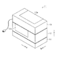
図1に示すように、液体噴射システムとしてのインクジェット式プリンタシステム11は、液体噴射装置としてのインクジェット式プリンタ12と、液体噴射付属装置及び液体供給装置としてのインク供給装置13と、インク回収装置14とを備えている。すなわち、インクジェット式プリンタ12の下側には、該インクジェット式プリンタ12に対してインク回収装置14が着脱自在に配置されているとともに、インクジェット式プリンタ12の上側には、該インクジェット式プリンタ12に対してインク供給装置13が着脱自在に配置されている。   As shown in FIG. 1, an ink jet printer system 11 serving as a liquid ejecting system includes an ink jet printer 12 serving as a liquid ejecting apparatus, an ink supplying apparatus 13 serving as a liquid ejecting accessory apparatus and a liquid supplying apparatus, and an ink collecting apparatus 14. And. That is, an ink collecting device 14 is detachably disposed below the ink jet printer 12 with respect to the ink jet printer 12, and above the ink jet printer 12 with respect to the ink jet printer 12. The ink supply device 13 is detachably disposed.

インクジェット式プリンタ12、インク供給装置13、及びインク回収装置14は、いずれも略直方体状をなしているとともに、左右の幅及び前後の幅が互いに同じになっている。すなわち、インクジェット式プリンタ12、インク供給装置13、及びインク回収装置14は、これらが組み合わせて使用される場合に各々の前後の両側面及び左右の両側面がそれぞれ互いに面一となるように形成されている。   The ink jet printer 12, the ink supply device 13, and the ink recovery device 14 all have a substantially rectangular parallelepiped shape, and the left and right widths and the front and rear widths are the same. That is, the ink jet printer 12, the ink supply device 13, and the ink recovery device 14 are formed so that the front and rear side surfaces and the left and right side surfaces are flush with each other when they are used in combination. ing.

インクジェット式プリンタ12の前面には、前蓋12aが開閉自在に設けられ、該前蓋12aを開けることで出現する開口からターゲットとしての記録用紙20(図2参照)が排紙されるようになっている。また、インク供給装置13の上面には、上蓋13aが開閉自在に設けられ、該上蓋13aを開けることで出現する開口から該インク供給装置13内のメンテナンスを行うことができるようになっている。   A front cover 12a is provided on the front surface of the ink jet printer 12 so as to be freely opened and closed, and a recording sheet 20 (see FIG. 2) as a target is discharged from an opening that appears when the front cover 12a is opened. ing. Further, an upper lid 13a is provided on the upper surface of the ink supply device 13 so as to be openable and closable. Maintenance inside the ink supply device 13 can be performed from an opening that appears when the upper lid 13a is opened.

次に、インクジェット式プリンタ12の構成について詳述する。
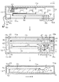
図2の中央部に示すように、インクジェット式プリンタ12は、四角箱状をなす装置本体としての本体ケース15を備えている。本体ケース15内の左端寄り位置には、本体ケース15内を左右に区画する左側フレーム16が立設されているとともに、左右方向における中央部よりもやや右寄りの位置には、左側フレーム16の高さの半分程度の高さの右側フレーム17が立設されている。
Next, the configuration of the ink jet printer 12 will be described in detail.
As shown in the central part of FIG. 2, the ink jet printer 12 includes a main body case 15 as a main body of the apparatus having a square box shape. A left frame 16 that divides the inside of the main body case 15 in the left and right directions is erected at a position closer to the left end in the main body case 15, and a height of the left frame 16 is slightly higher than the center in the left and right direction. A right frame 17 having a height of about half the height is erected.

両フレーム16,17間には、プラテン18が架設され、該プラテン18上には、図示しない紙送りローラが設けられている。本体ケース15内において左側フレーム16の左側には、紙送りモータ19が設けられ、該紙送りモータ19は、プラテン18上の紙送りローラに接続されている。そして、この紙送りモータ19の駆動により、紙送りローラが回転されてプラテン18上に記録用紙20が給送されるようになっている。また、本体ケース15内の上下方向における中央部よりもやや上方域において該本体ケース15の右側壁と左側フレーム16との間には、プラテン18の長手方向と平行に、棒状のガイド部材21が架設されている。   A platen 18 is installed between the frames 16 and 17, and a paper feed roller (not shown) is provided on the platen 18. A paper feed motor 19 is provided on the left side of the left frame 16 in the main body case 15, and the paper feed motor 19 is connected to a paper feed roller on the platen 18. By driving the paper feed motor 19, the paper feed roller is rotated so that the recording paper 20 is fed onto the platen 18. In addition, a rod-shaped guide member 21 is provided between the right side wall of the main body case 15 and the left frame 16 in a region slightly above the central portion in the vertical direction in the main body case 15, parallel to the longitudinal direction of the platen 18. It is erected.

ガイド部材21には、キャリッジ22が、該ガイド部材21の軸線方向に往復移動可能に挿通支持されている。キャリッジ22は、本体ケース15内にガイド部材21と沿うように設けられたタイミングベルト23を介して本体ケース15の後壁内面に設けられたキャリッジモータ24に連結されている。そして、キャリッジ22は、キャリッジモータ24の駆動により、ガイド部材21に沿って往復移動されるようになっている。そして、本体ケース15の上壁には、該本体ケース15の内外を貫通する第1長孔15aがキャリッジ22の移動範囲と対応するように形成されている。   A carriage 22 is inserted into and supported by the guide member 21 so as to be able to reciprocate in the axial direction of the guide member 21. The carriage 22 is connected to a carriage motor 24 provided on the inner surface of the rear wall of the main body case 15 via a timing belt 23 provided along the guide member 21 in the main body case 15. The carriage 22 is reciprocated along the guide member 21 by driving the carriage motor 24. A first long hole 15 a penetrating the inside and outside of the main body case 15 is formed on the upper wall of the main body case 15 so as to correspond to the movement range of the carriage 22.

キャリッジ22の下面には、液体噴射ヘッドとしての記録ヘッド25が搭載され、該記録ヘッド25の下面は、ノズル形成面25aになっている。ノズル形成面25aには複数(本実施形態では4つ)のノズル26が設けられ、これらノズル26毎に図示しない圧電素子が配置されている。また、キャリッジ22における記録ヘッド25の上側には、噴射液体貯留部としてのサブインクタンク27が複数(本実施形態では4つ)左右方向に並設されている。各サブインクタンク27内には、顔料を含む複数色(本実施形態では4色)の液体としてのインクがそれぞれ記録ヘッド25に供給可能に収容されている。   A recording head 25 as a liquid jet head is mounted on the lower surface of the carriage 22, and the lower surface of the recording head 25 is a nozzle forming surface 25a. A plurality (four in this embodiment) of nozzles 26 are provided on the nozzle forming surface 25a, and a piezoelectric element (not shown) is disposed for each nozzle 26. In addition, a plurality of (four in this embodiment) sub-ink tanks 27 as jet liquid storage portions are arranged in the left-right direction above the recording head 25 in the carriage 22. In each sub ink tank 27, ink as liquids of a plurality of colors (four colors in the present embodiment) including a pigment is accommodated so as to be supplied to the recording head 25.

そして、記録ヘッド25にノズル26毎に対応して備えられた圧電素子の駆動により、各サブインクタンク27から記録ヘッド25へと各インクがそれぞれ供給され、該各インクが各ノズル26からプラテン18上に給送された記録用紙20にそれぞれ噴射されて印刷が行われるようになっている。なお、各サブインクタンク27の上端部には、それぞれ液体供給側接続部としてのインク供給側接続部28が設けられ、該各インク供給側接続部28には、各サブインクタンク27へ供給される各インクの供給量を計測する供給量計測手段としての流量計87(図7参照)が設けられている。   Each of the inks is supplied from each of the sub ink tanks 27 to the recording head 25 by driving the piezoelectric element corresponding to each nozzle 26 in the recording head 25, and each ink is supplied from each nozzle 26 to the platen 18. Printing is performed by being jetted onto the recording paper 20 fed upward. An ink supply side connection portion 28 as a liquid supply side connection portion is provided at an upper end portion of each sub ink tank 27, and the ink supply side connection portion 28 is supplied to each sub ink tank 27. A flow meter 87 (see FIG. 7) is provided as supply amount measuring means for measuring the supply amount of each ink.

本体ケース15内の右側フレーム17よりも右端部側に位置する非印刷領域(ホームポジション)には、非印刷時に記録ヘッド25のノズル形成面25a(各ノズル26)を封止するための有底四角箱状のキャップ29が設けられている。キャップ29の底壁の中央部には、該キャップ29の内外を貫通する図示しない排出孔が設けられている。この排出孔には、可撓性材料よりなる排出チューブ30の基端側(上流側)が接続されているとともに、該排出チューブ30の先端側(下流側)は、本体ケース15の底壁に設けられたインク回収側接続部31に接続されている。なお、キャップ29内と排出チューブ30内とは、排出孔を介して連通している。   In a non-printing region (home position) positioned on the right end side of the right frame 17 in the main body case 15, a bottomed surface for sealing the nozzle forming surface 25a (each nozzle 26) of the recording head 25 during non-printing. A square box-shaped cap 29 is provided. At the center of the bottom wall of the cap 29, a discharge hole (not shown) penetrating the inside and outside of the cap 29 is provided. A base end side (upstream side) of the discharge tube 30 made of a flexible material is connected to the discharge hole, and a distal end side (downstream side) of the discharge tube 30 is connected to the bottom wall of the main body case 15. It is connected to the provided ink collection side connection part 31. Note that the inside of the cap 29 and the inside of the discharge tube 30 communicate with each other through a discharge hole.

キャップ29の下側における本体ケース15内の底面上には、一対の四角形状をなす支持板32が排出チューブ30を前後方向に挟んで対抗する両位置に立設されている。両支持板32には、これらの左下部から右上部にかけて延びるように摺動長孔32aがそれぞれ貫通形成されている。キャップ29の下面には、排出チューブ30を左右方向に挟んで対抗する両位置に、下方に向かって延びる左側支持棒33及び右側支持棒34が並設されている。   On the bottom surface in the main body case 15 on the lower side of the cap 29, a pair of square-shaped support plates 32 are erected at opposing positions sandwiching the discharge tube 30 in the front-rear direction. Sliding long holes 32a are formed in both support plates 32 so as to extend from the lower left part to the upper right part. On the lower surface of the cap 29, a left side support bar 33 and a right side support bar 34 that extend downward are juxtaposed at both positions facing the discharge tube 30 in the left-right direction.

左側支持棒33及び右側支持棒34は、これらの下端がそれぞれ両摺動長孔32aに挟まれる位置まで真下に向かって真っ直ぐに延びている。すなわち、左側支持棒33は、両摺動長孔32aが傾斜している分だけ右側支持棒34よりも長くなっている。なお、左側支持棒33と右側支持棒34との距離は、両摺動長孔32aの長さよりも短く設定されている。   The left support bar 33 and the right support bar 34 extend straight down toward the position where their lower ends are sandwiched between the sliding long holes 32a. That is, the left side support bar 33 is longer than the right side support bar 34 by the amount that both sliding long holes 32a are inclined. Note that the distance between the left support rod 33 and the right support rod 34 is set to be shorter than the length of the sliding long holes 32a.

左側支持棒33及び右側支持棒34の下端は、前後方向に伸びる左側摺動棒33a及び右側摺動棒34aの中央部にそれぞれ接続されている。左側摺動棒33a及び右側摺動棒34aのそれぞれの両端部は、両摺動長孔32a内に、それぞれ該両摺動長孔32a内を摺動可能に挿通支持されている。また、キャップ29の右側面には、L字棒状の誘導部材35の基端部が接続されている。すなわち、誘導部材35は、基端部から右方向へ水平に延びた後、中央部で上方に向かって直角に屈曲され、先端部が記録ヘッド25よりも上側まで達している。   Lower ends of the left support bar 33 and the right support bar 34 are respectively connected to the center portions of the left slide bar 33a and the right slide bar 34a extending in the front-rear direction. Both end portions of the left sliding rod 33a and the right sliding rod 34a are inserted into and supported by the sliding long holes 32a so as to be slidable in the sliding long holes 32a. In addition, a base end portion of an L-shaped guide member 35 is connected to the right side surface of the cap 29. That is, the guide member 35 extends horizontally from the base end portion in the right direction, and then bends at a right angle upward at the center portion, and the tip end portion reaches the upper side of the recording head 25.

そして、キャリッジ22を非印刷領域に移動させた場合に、該キャリッジ22の右側面が誘導部材35の先端部の左側面に当接し、該誘導部材35がキャップ29とともに右方向に押圧されるようになっている。この押圧作用により、左側摺動棒33a及び右側摺動棒34aのそれぞれの両端部が、両摺動長孔32a内に沿って右上方向に摺動し、この摺動にともなってキャップ29も右上方向に移動され、該キャップ29により記録ヘッド25のノズル形成面25a(各ノズル26)が封止されるようになっている。   When the carriage 22 is moved to the non-printing area, the right side surface of the carriage 22 comes into contact with the left side surface of the distal end portion of the guide member 35 so that the guide member 35 is pressed together with the cap 29 in the right direction. It has become. Due to this pressing action, both end portions of the left sliding rod 33a and the right sliding rod 34a slide in the upper right direction along both sliding long holes 32a, and the cap 29 also moves to the upper right along with this sliding. The nozzle formation surface 25 a (each nozzle 26) of the recording head 25 is sealed by the cap 29.

なお、キャリッジ22を印刷領域に移動させた場合には、重力により、左側摺動棒33a及び右側摺動棒34aのそれぞれの両端部が、両摺動長孔32a内に沿って左下方向に摺動し、この摺動にともなってキャップ29も左下方向に移動されるようになっている。   When the carriage 22 is moved to the printing area, both ends of the left sliding rod 33a and the right sliding rod 34a slide in the lower left direction along both sliding long holes 32a due to gravity. The cap 29 is also moved in the lower left direction along with this sliding.

本体ケース15内の左端上部には、インクジェット式プリンタ12を単独で使用する場合の電力供給源となる充電池36が設けられ、該充電池36の下側には、制御手段、充電時間計測手段、及び供給時間計測手段としての制御部82が設けられている。また、本体ケース15の上面の4つのコーナ部には、それぞれ第1凹部15bが形成されているとともに、本体ケース15の下面の4つのコーナ部には、それぞれ第1凸部15cが突出形成されている。   A rechargeable battery 36 serving as a power supply source when the ink jet printer 12 is used alone is provided at the upper left end in the main body case 15. A control unit and a charging time measuring unit are provided below the rechargeable battery 36. And a control unit 82 as a supply time measuring means. In addition, first concave portions 15 b are formed in the four corner portions on the upper surface of the main body case 15, and first convex portions 15 c are formed to protrude from the four corner portions on the lower surface of the main body case 15. ing.

さらに、本体ケース15の上面の左端部には、充電側接続部としての平板状の充電側接続端子83が突出形成され、本体ケース15の下面の左端部には、平板状の電気接続端子84が突出形成されている。   Furthermore, a flat charging side connection terminal 83 as a charging side connection portion is formed to protrude from the left end portion of the upper surface of the main body case 15, and a flat electric connection terminal 84 is formed at the left end portion of the lower surface of the main body case 15. Projectingly formed.

ここで、インク供給側接続部28及びインク回収側接続部31の構成について詳述する。
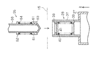
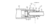
図3の下部に示すように、インク供給側接続部28は、サブインクタンク27の上端部に、内部が該サブインクタンク27内と連通するように接続された円筒状の供給接続ケース37を備えている。供給接続ケース37の内周面において、上端部には円環状の供給上側フランジ38が形成されているとともに、下端部には円環状の供給下側フランジ39が形成されている。供給下側フランジ39の上面には、コイルバネ40が配置され、該コイルバネ40の上面には、円板状のインク供給側弁41が配置されている。
Here, the configuration of the ink supply side connection portion 28 and the ink recovery side connection portion 31 will be described in detail.
As shown in the lower part of FIG. 3, the ink supply side connection portion 28 has a cylindrical supply connection case 37 connected to the upper end portion of the sub ink tank 27 so that the inside communicates with the inside of the sub ink tank 27. I have. On the inner peripheral surface of the supply connection case 37, an annular supply upper flange 38 is formed at the upper end portion, and an annular supply lower flange 39 is formed at the lower end portion. A coil spring 40 is disposed on the upper surface of the supply lower flange 39, and a disk-shaped ink supply side valve 41 is disposed on the upper surface of the coil spring 40.

このインク供給側弁41の外径は、供給上側フランジ38の内径よりも大きく、かつ供給接続ケース37の内径よりも小さくなるように設定されている。そして、インク供給側弁41は、該インク供給側弁41の上面が供給上側フランジ38の下面に密着するようにコイルバネ40によって付勢されている。したがって、インク供給側弁41によって供給接続ケース37内の通路が閉塞され、供給上側フランジ38がインク供給側弁41の弁座として機能するようになっている。   The outer diameter of the ink supply side valve 41 is set to be larger than the inner diameter of the upper supply flange 38 and smaller than the inner diameter of the supply connection case 37. The ink supply side valve 41 is urged by a coil spring 40 so that the upper surface of the ink supply side valve 41 is in close contact with the lower surface of the supply upper flange 38. Accordingly, the passage in the supply connection case 37 is closed by the ink supply side valve 41, and the supply upper flange 38 functions as a valve seat for the ink supply side valve 41.

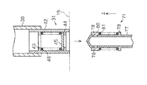
図5の上部に示すように、インク回収側接続部31は、排出チューブ30の先端(下端)開口部内に、内部が該排出チューブ30内と連通するように密嵌された円筒状の回収接続ケース42を備えている。回収接続ケース42の内周面において、上端部には円環状の回収上側フランジ43が形成されているとともに、下端部には円環状の回収下側フランジ44が形成されている。回収下側フランジ44の上面には、円板状のインク回収側弁45が配置され、該インク回収側弁45の上面と回収上側フランジ43の下面との間には、コイルバネ46が配置されている。   As shown in the upper part of FIG. 5, the ink collection side connection portion 31 is a cylindrical collection connection that is tightly fitted in the opening (lower end) opening of the discharge tube 30 so that the inside communicates with the inside of the discharge tube 30. A case 42 is provided. On the inner peripheral surface of the recovery connection case 42, an annular recovery upper flange 43 is formed at the upper end portion, and an annular recovery lower flange 44 is formed at the lower end portion. A disk-shaped ink recovery side valve 45 is disposed on the upper surface of the recovery lower flange 44, and a coil spring 46 is disposed between the upper surface of the ink recovery side valve 45 and the lower surface of the recovery upper flange 43. Yes.

このインク回収側弁45の外径は、回収下側フランジ44の内径よりも大きく、かつ回収接続ケース42の内径よりも小さくなるように設定されている。そして、インク回収側弁45は、該インク回収側弁45の下面が回収下側フランジ44の上面に密着するようにコイルバネ46によって付勢されている。したがって、インク回収側弁45によって回収接続ケース42内の通路が閉塞され、回収下側フランジ44がインク回収側弁45の弁座として機能するようになっている。   The outer diameter of the ink collection side valve 45 is set to be larger than the inner diameter of the lower collection flange 44 and smaller than the inner diameter of the collection connection case 42. The ink recovery side valve 45 is urged by a coil spring 46 so that the lower surface of the ink recovery side valve 45 is in close contact with the upper surface of the recovery lower flange 44. Therefore, the passage in the recovery connection case 42 is closed by the ink recovery side valve 45, and the recovery lower flange 44 functions as a valve seat for the ink recovery side valve 45.

次に、インク供給装置13の構成について詳述する。
図2の上部に示すように、インク供給装置13は、四角箱状をなす供給装置ケース50を備えている。供給装置ケース50の底壁には、該供給装置ケース50の内外を貫通する第2長孔50aが、本体ケース15の上壁に形成された第1長孔15aと対応するように形成されている。供給装置ケース50内の上部中央部には、供給液体貯留部としての供給インクタンク51が複数(本実施形態では4つ)左右方向に並設されている。
Next, the configuration of the ink supply device 13 will be described in detail.
As shown in the upper part of FIG. 2, the ink supply device 13 includes a supply device case 50 having a rectangular box shape. A second long hole 50 a penetrating the inside and outside of the supply device case 50 is formed in the bottom wall of the supply device case 50 so as to correspond to the first long hole 15 a formed in the upper wall of the main body case 15. Yes. A plurality of (four in the present embodiment) supply ink tanks 51 as supply liquid storage portions are arranged in the left-right direction at the upper central portion in the supply device case 50.

各供給インクタンク51内には、各サブインクタンク27内にそれぞれ供給するためのインクがそれぞれ収容されている。すなわち、各供給インクタンク51内には、各サブインクタンク27内にそれぞれ収容されているインクに対応した同じ色のインクがそれぞれ収容されている。そして、各供給インクタンク51の上端部には、該各供給インクタンク51内に各インクをそれぞれ補充するための図示しない開閉自在の蓋体が設けられている。   Each supply ink tank 51 contains ink to be supplied to each sub ink tank 27. That is, in each supply ink tank 51, ink of the same color corresponding to the ink stored in each sub ink tank 27 is stored. An openable / closable lid (not shown) for replenishing each ink in each supply ink tank 51 is provided at the upper end of each supply ink tank 51.

供給装置ケース50内の左端部には、加圧手段としての加圧ポンプ52が設けられている。加圧ポンプ52には、複数(本実施形態では4本)の加圧管53の一端がそれぞれ接続されているとともに、該各加圧管53の他端は、各供給インクタンク51の上端部にそれぞれ接続されている。   A pressurizing pump 52 as a pressurizing unit is provided at the left end in the supply device case 50. One end of a plurality of (four in this embodiment) pressurizing pipes 53 is connected to the pressurizing pump 52, and the other end of each pressurizing pipe 53 is connected to the upper end of each supply ink tank 51. It is connected.

供給装置ケース50内の底面上には、第2長孔50aを跨ぐように四角板状の摺動部材54が、該供給装置ケース50内の底面上を該第2長孔50aに沿って摺動自在に配置されている。摺動部材54の下面には、液体供給用接続口としての有底円筒状の複数(本実施形態では4本)のインク供給用接続部材55がインクジェット式プリンタ12のインク供給側接続部28と対応するように左右方向に並設されている。   On the bottom surface in the supply device case 50, a rectangular plate-like sliding member 54 is slid along the second long hole 50a on the bottom surface in the supply device case 50 so as to straddle the second long hole 50a. Arranged freely. On the lower surface of the sliding member 54, a plurality of bottomed cylindrical (four in this embodiment) ink supply connection members 55 serving as liquid supply connection ports are connected to the ink supply side connection portion 28 of the inkjet printer 12. It is arranged in parallel in the left-right direction so as to correspond.

この場合、各インク供給用接続部材55は、第2長孔50a内に挿通されているとともに、真下に向かって延びている。さらに、この場合、各インク供給用接続部材55の中央部から先端部(下端部)にかけての部位が、供給装置ケース50の下面よりも下側に突出している。そして、第2長孔50aの前後方向の幅は、インク供給用接続部材55の外径よりも大きく、かつ摺動部材54の前後方向の幅よりも小さくなるように設定されている。   In this case, each ink supply connecting member 55 is inserted into the second elongated hole 50a and extends downward. Further, in this case, a portion from the center portion to the tip portion (lower end portion) of each ink supply connecting member 55 protrudes below the lower surface of the supply device case 50. The width of the second long hole 50a in the front-rear direction is set to be larger than the outer diameter of the ink supply connecting member 55 and smaller than the width of the sliding member 54 in the front-rear direction.

各供給インクタンク51の下端部には、可撓性材料よりなるインク供給チューブ56の一端がそれぞれ接続されているとともに、該各インク供給チューブ56の他端は、摺動部材54の上面に接続されている。各インク供給チューブ56内と各インク供給用接続部材55内とは、該各インク供給チューブ56及び該各インク供給用接続部材55と対応するように摺動部材54内にそれぞれ形成された4つの挿通路54aを介してそれぞれ連通している。   One end of an ink supply tube 56 made of a flexible material is connected to the lower end portion of each supply ink tank 51, and the other end of each ink supply tube 56 is connected to the upper surface of the sliding member 54. Has been. Each ink supply tube 56 and each ink supply connection member 55 are formed in four sliding members 54 so as to correspond to each ink supply tube 56 and each ink supply connection member 55. Each communicates via the insertion passage 54a.

なお、本実施形態では、各インク供給チューブ56、各インク供給用接続部材55、及び挿通路54aにより液体供給路が構成され、該液体供給路、各供給インクタンク51、各加圧管53、及び加圧ポンプ52により液体供給機構が構成されている。   In the present embodiment, each ink supply tube 56, each ink supply connection member 55, and the insertion path 54a constitute a liquid supply path. The liquid supply path, each supply ink tank 51, each pressure tube 53, and The pressurizing pump 52 constitutes a liquid supply mechanism.

供給装置ケース50の下面の4つのコーナ部には、インク供給装置13をインクジェット式プリンタ12上に配置する際に、本体ケース15の各第1凹部15bにそれぞれ対応して該各第1凹部15bに挿入される第2凸部50bが下方に向かってそれぞれ突出形成されている。   At the four corners on the lower surface of the supply device case 50, when the ink supply device 13 is disposed on the ink jet printer 12, the first recesses 15b correspond to the first recesses 15b of the main body case 15, respectively. The second convex portions 50b inserted into the projections are formed so as to protrude downward.

供給装置ケース50内の左端下部には、充電器57が設けられている。充電器57には、供給装置ケース50の左側壁に設けられた図示しない貫通孔に通された電源コード58の一端が接続され、該電源コード58の他端には、プラグ59が設けられている。そして、プラグ59を図示しないコンセント(電源)に差し込むことで充電器57に電力が供給されるようになっている。   A charger 57 is provided at the lower left end in the supply device case 50. One end of a power cord 58 passed through a through hole (not shown) provided on the left side wall of the supply device case 50 is connected to the charger 57, and a plug 59 is provided on the other end of the power cord 58. Yes. Then, power is supplied to the charger 57 by inserting the plug 59 into an outlet (power source) (not shown).

また、供給装置ケース50の下面の左端部には、本体ケース15の上面に設けられた充電側接続端子83と対応するように、充電用接続口としての平板状の充電用接続端子85が突出形成されている。なお、本実施形態では、充電器57及び充電用接続端子85により充電機構が構成され、該充電機構、電源コード58、及びプラグ59により充電装置が構成されている。さらに、本実施形態では、充電装置がインク供給装置13に組み込まれている。   Further, at the left end of the lower surface of the supply device case 50, a flat charging connection terminal 85 as a charging connection port protrudes so as to correspond to the charging side connection terminal 83 provided on the upper surface of the main body case 15. Is formed. In the present embodiment, the charger 57 and the charging connection terminal 85 constitute a charging mechanism, and the charging mechanism, the power cord 58 and the plug 59 constitute a charging device. Furthermore, in the present embodiment, the charging device is incorporated in the ink supply device 13.

そして、インク供給装置13をインクジェット式プリンタ12上に配置した際に、充電側接続端子83と充電用接続端子85とが接触することで、充電装置を含むインク供給装置13とインクジェット式プリンタ12とが電気的に接続されるようになっている。なお、各第1凹部15b及び各第2凸部50bは、インク供給装置13をインクジェット式プリンタ12上に位置決め配置するための位置決め手段を構成している。   When the ink supply device 13 is disposed on the ink jet printer 12, the charging side connection terminal 83 and the charge connection terminal 85 come into contact with each other, so that the ink supply device 13 including the charging device and the ink jet printer 12 Are electrically connected. Each first concave portion 15 b and each second convex portion 50 b constitute positioning means for positioning the ink supply device 13 on the ink jet printer 12.

ここで、インク供給用接続部材55の構成について詳述する。
図3の上部に示すように、インク供給用接続部材55は、有底円筒状の挿入本体60を備えている。挿入本体60の外径は、供給接続ケース37内に設けられた供給上側フランジ38の内径よりも僅かに小さく設定され、該挿入本体60の下端面は、円錐状をなしている。挿入本体60の下端部における周壁には、該周壁を貫通するように互いに対向する一対の供給孔61が形成されている。挿入本体60の外周面上における両供給孔61よりも上側には、円環状の外側フランジ62が設けられている。
Here, the configuration of the ink supply connecting member 55 will be described in detail.
As shown in the upper part of FIG. 3, the ink supply connection member 55 includes a bottomed cylindrical insertion body 60. The outer diameter of the insertion body 60 is set slightly smaller than the inner diameter of the supply upper flange 38 provided in the supply connection case 37, and the lower end surface of the insertion body 60 has a conical shape. A pair of supply holes 61 that are opposed to each other so as to penetrate the peripheral wall are formed in the peripheral wall at the lower end of the insertion body 60. An annular outer flange 62 is provided above the supply holes 61 on the outer peripheral surface of the insertion body 60.

挿入本体60の外周面上には、両供給孔61を塞ぐように円筒状のインク供給用弁63が該挿入本体60の外周面上を摺動可能に密着され、該インク供給用弁63は、コイルバネ64を介して外側フランジ62に連結支持されている。すなわち、インク供給用弁63の上端面と外側フランジ62の下面とがコイルバネ64を介して連結されている。なお、インク供給用弁63の外径は、供給接続ケース37内に設けられた供給上側フランジ38の内径よりも大きく、かつ供給接続ケース37の内径よりも小さく設定されている。   A cylindrical ink supply valve 63 is slidably contacted on the outer peripheral surface of the insertion body 60 so as to block both supply holes 61, and the ink supply valve 63 is slidable on the outer peripheral surface of the insertion body 60. The outer flange 62 is connected and supported via a coil spring 64. That is, the upper end surface of the ink supply valve 63 and the lower surface of the outer flange 62 are connected via the coil spring 64. The outer diameter of the ink supply valve 63 is set larger than the inner diameter of the upper supply flange 38 provided in the supply connection case 37 and smaller than the inner diameter of the supply connection case 37.

次に、インク回収装置14の構成について詳述する。
図2の下部に示すように、インク回収装置14は、四角箱状をなす回収装置ケース70を備えている。回収装置ケース70の上壁における右端部には、有底円筒状のインク回収用接続部材71がインクジェット式プリンタ12のインク回収側接続部31と対応するように貫設されている。この場合、インク回収用接続部材71の上端部は、回収装置ケース70の上面よりも上側に突出している。
Next, the configuration of the ink recovery device 14 will be described in detail.
As shown in the lower part of FIG. 2, the ink recovery device 14 includes a recovery device case 70 having a square box shape. A bottomed cylindrical ink collecting connection member 71 is provided at the right end of the upper wall of the collecting device case 70 so as to correspond to the ink collecting side connecting portion 31 of the ink jet printer 12. In this case, the upper end portion of the ink recovery connecting member 71 protrudes above the upper surface of the recovery device case 70.

回収装置ケース70内の底面上における中央部から左端部にかけての位置には、回収したインクを収容するための上端が開口した四角箱状の回収容器72が配設されている。回収容器72内には、回収したインクを吸収保持するためのインク吸収材73が充填されている。インク吸収材73の右上端部には、該インク吸収材73の一部を断面L字状に切り欠いてなる切欠凹部73aが形成されている。   A square box-like collection container 72 having an open upper end for accommodating the collected ink is disposed on the bottom surface in the collection device case 70 from the center to the left end. The collection container 72 is filled with an ink absorbing material 73 for absorbing and holding the collected ink. A cutout recess 73 a is formed at the upper right end of the ink absorber 73 by cutting out a part of the ink absorber 73 in an L-shaped cross section.

インク回収用接続部材71の下端には、可撓性材料よりなるインク回収チューブ74の一端が接続され、該インク回収チューブ74の他端は、回収容器72内におけるインク吸収材73の切欠凹部73a上に挿入されている。インク回収チューブ74におけるインク回収用接続部材71側の部分の途中位置には、チューブポンプ75が設けられ、該チューブポンプ75の駆動により、インク回収用接続部材71側から回収容器72側に向かってインクが吸引されるようになっている。   One end of an ink recovery tube 74 made of a flexible material is connected to the lower end of the ink recovery connection member 71, and the other end of the ink recovery tube 74 is a notch recess 73 a of the ink absorbing material 73 in the recovery container 72. Is inserted above. A tube pump 75 is provided in the middle of the portion of the ink collection tube 74 on the ink collection connection member 71 side. By driving the tube pump 75, the ink collection connection member 71 side is moved toward the collection container 72 side. Ink is sucked.

回収装置ケース70の上面の4つのコーナ部には、インクジェット式プリンタ12をインク回収装置14上に配置する際に、本体ケース15の各第1凸部15cにそれぞれ対応して該各第1凸部15cが挿入される第2凹部70aが形成されている。さらに、回収装置ケース70の上面の左端部には、本体ケース15の下面に設けられた電気接続端子84と対応するように、電気接続端子86が突出形成されている。また、回収装置ケース70内の左上部には、インク回収装置14の電力供給源となる充電池76が設けられている。   At the four corners on the upper surface of the collecting device case 70, when the ink jet printer 12 is placed on the ink collecting device 14, the first protruding portions correspond to the first protruding portions 15 c of the main body case 15. A second recess 70a into which the portion 15c is inserted is formed. Furthermore, an electrical connection terminal 86 is formed to project from the left end of the upper surface of the recovery device case 70 so as to correspond to the electrical connection terminal 84 provided on the lower surface of the main body case 15. A rechargeable battery 76 serving as a power supply source for the ink recovery device 14 is provided in the upper left portion of the recovery device case 70.

そして、インク供給装置13をインクジェット式プリンタ12上に配置するとともに、該インクジェット式プリンタ12をインク回収装置14上に配置した際に、充電装置を含むインク供給装置13、インクジェット式プリンタ12、及びインク回収装置14が互いに電気的に接続されるようになっている。なお、各第1凸部15c及び各第2凹部70aは、インクジェット式プリンタ12をインク回収装置14上に位置決め配置するための位置決め手段を構成している。   When the ink supply device 13 is disposed on the ink jet printer 12 and the ink jet printer 12 is disposed on the ink recovery device 14, the ink supply device 13 including the charging device, the ink jet printer 12, and the ink The collection devices 14 are electrically connected to each other. Each first convex portion 15 c and each second concave portion 70 a constitute a positioning means for positioning the ink jet printer 12 on the ink recovery device 14.

ここで、インク回収用接続部材71の構成について詳述する。
図5の下部に示すように、インク回収用接続部材71は、有底円筒状の挿入本体77を備えている。挿入本体77の外径は、回収接続ケース42内に設けられた回収下側フランジ44の内径よりも僅かに小さく設定され、該挿入本体77の上端面は、円錐状をなしている。挿入本体77の上端部における周壁には、該周壁を貫通するように互いに対向する一対の回収孔78が形成されている。挿入本体77の外周面上における両回収孔78よりも下側には、円環状の外側フランジ79が設けられている。
Here, the configuration of the ink collecting connection member 71 will be described in detail.
As shown in the lower part of FIG. 5, the ink recovery connecting member 71 includes a bottomed cylindrical insertion body 77. The outer diameter of the insertion body 77 is set slightly smaller than the inner diameter of the recovery lower flange 44 provided in the recovery connection case 42, and the upper end surface of the insertion body 77 has a conical shape. A pair of recovery holes 78 are formed on the peripheral wall at the upper end of the insertion body 77 so as to face each other so as to penetrate the peripheral wall. An annular outer flange 79 is provided below the recovery holes 78 on the outer peripheral surface of the insertion body 77.

挿入本体77の外周面上には、両回収孔78を塞ぐように円筒状のインク回収用弁80が該挿入本体77の外周面上を摺動可能に密着され、該インク回収用弁80は、コイルバネ81を介して外側フランジ79に連結支持されている。すなわち、インク回収用弁80の下端面と外側フランジ79の上面とがコイルバネ81を介して連結されている。なお、インク回収用弁80の外径は、回収接続ケース42内に設けられた回収下側フランジ44の内径よりも大きく、かつ回収接続ケース42の内径よりも小さく設定されている。   On the outer peripheral surface of the insertion body 77, a cylindrical ink recovery valve 80 is slidably adhered on the outer peripheral surface of the insertion body 77 so as to block both recovery holes 78. The ink recovery valve 80 is The outer flange 79 is connected and supported via a coil spring 81. That is, the lower end surface of the ink recovery valve 80 and the upper surface of the outer flange 79 are connected via the coil spring 81. The outer diameter of the ink recovery valve 80 is set larger than the inner diameter of the recovery lower flange 44 provided in the recovery connection case 42 and smaller than the inner diameter of the recovery connection case 42.

次に、インク供給装置13をインクジェット式プリンタ12上に配置するとともに、該インクジェット式プリンタ12をインク回収装置14上に配置した際のインクジェット式プリンタシステム11の電気的構成について説明する。   Next, an electrical configuration of the ink jet printer system 11 when the ink supply device 13 is disposed on the ink jet printer 12 and the ink jet printer 12 is disposed on the ink recovery device 14 will be described.

図7に示すように、充電器57は、加圧ポンプ52、充電池36、及び充電池76と電気的に接続され、該充電器57により、充電池36及び充電池76の充電が行われるとともに、加圧ポンプ52に対して駆動電力が供給されるようになっている。充電池76は、チューブポンプ75と電気的に接続され、該充電池76により該チューブポンプ75に対して駆動電力が供給されるようになっている。   As shown in FIG. 7, the charger 57 is electrically connected to the pressure pump 52, the rechargeable battery 36, and the rechargeable battery 76, and the rechargeable battery 36 and the rechargeable battery 76 are charged by the charger 57. At the same time, driving power is supplied to the pressurizing pump 52. The rechargeable battery 76 is electrically connected to the tube pump 75, and driving power is supplied to the tube pump 75 by the rechargeable battery 76.

充電池36には、該充電池36と電気的に接続されるように、該充電池36に充電される電力量を計測するための電力量計測手段としての電力計88が設けられている。この電力計88は、充電池36が満充電(最大限に充電)にされた状態であることを検出可能になっている。さらに、充電池36は、制御部82、キャリッジモータ24、紙送りモータ19、及び流量計87と電気的に接続され、該充電池36により、これら制御部82、キャリッジモータ24、紙送りモータ19、及び流量計87に対して駆動電力が供給されるようになっている。   The rechargeable battery 36 is provided with a wattmeter 88 as a power amount measuring means for measuring the amount of power charged in the rechargeable battery 36 so as to be electrically connected to the rechargeable battery 36. The wattmeter 88 can detect that the rechargeable battery 36 is fully charged (maximum charge). Further, the rechargeable battery 36 is electrically connected to the control unit 82, the carriage motor 24, the paper feed motor 19, and the flow meter 87, and the control unit 82, the carriage motor 24, and the paper feed motor 19 are connected by the rechargeable battery 36. , And the driving power is supplied to the flow meter 87.

制御部82は、加圧ポンプ52、キャリッジモータ24、及び紙送りモータ19と電気的に接続され、該制御部82により、これら加圧ポンプ52、キャリッジモータ24、及び紙送りモータ19が駆動制御されるようになっている。また、制御部82には、予め実験等により求めた、各ノズル26から噴射するインク量と該インク量のインクを噴射するために必要な電力との関係を示すデータAが記憶されている。さらに、制御部82には、予め実験等により求めた、充電池36の充電時間と該充電時間に相当する電力量との関係を示すデータBが記憶されている。   The control unit 82 is electrically connected to the pressure pump 52, the carriage motor 24, and the paper feed motor 19, and the control unit 82 controls driving of the pressure pump 52, the carriage motor 24, and the paper feed motor 19. It has come to be. Further, the control unit 82 stores data A indicating the relationship between the amount of ink ejected from each nozzle 26 and the electric power necessary to eject the ink of the ink amount, which is obtained in advance through experiments or the like. Furthermore, the control unit 82 stores data B, which is obtained in advance through experiments or the like and indicates the relationship between the charging time of the rechargeable battery 36 and the amount of power corresponding to the charging time.

そして、制御部82は、電力計88及び流量計87と電気的に接続され、これら電力計88及び流量計87からそれぞれ入力される信号とデータAとに基づいて、充電池36に充電される電力量及び各サブインクタンク27へ供給される各インクの供給量をそれぞれ算出するようになっている。   And the control part 82 is electrically connected with the wattmeter 88 and the flowmeter 87, and is charged to the rechargeable battery 36 based on the signal and data A which are each input from these wattmeter 88 and the flowmeter 87. The amount of electric power and the amount of ink supplied to each sub ink tank 27 are calculated.

次に、本実施形態のインクジェット式プリンタシステム11が実行するインク供給処理ルーチンについて図8に示すフローチャートに基づいて説明する。
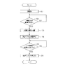
さて、充電池36の充電が開始されると、制御部82は、時間のカウントを始める(ステップS1)。次に、制御部82は、充電池36が満充電(最大限に充電)されたか否かを電力計88から入力される信号に基づいて判断する(ステップS2)。ステップS2で否定判定の場合、制御部82は、再びステップS2の処理を実行する。ステップS2で肯定判定の場合、制御部82は、時間のカウントを停止するとともに、充電池36が満充電されるまでに要した充電時間を算出する。
Next, an ink supply processing routine executed by the ink jet printer system 11 of the present embodiment will be described based on the flowchart shown in FIG.
Now, when charging of the rechargeable battery 36 is started, the controller 82 starts counting time (step S1). Next, the control unit 82 determines whether or not the rechargeable battery 36 is fully charged (maximum charging) based on a signal input from the wattmeter 88 (step S2). When a negative determination is made in step S2, the control unit 82 executes the process of step S2 again. If the determination in step S2 is affirmative, the control unit 82 stops counting the time and calculates the charging time required until the rechargeable battery 36 is fully charged.

そして、制御部82は、該充電時間とデータBとに基づいて充電池36が満充電されるまでに要した充電時間に相当する電力量を算出するとともに、該電力量で噴射可能なインク量をデータAに基づいて算出し、該インク量を所定量Sとして記憶する(ステップS3)。次に、制御部82は、加圧ポンプ52を駆動させる(ステップS4)。   Then, the control unit 82 calculates the amount of power corresponding to the charging time required until the rechargeable battery 36 is fully charged based on the charging time and the data B, and the amount of ink that can be ejected with the amount of power. Is calculated based on the data A, and the ink amount is stored as the predetermined amount S (step S3). Next, the control part 82 drives the pressurization pump 52 (step S4).

次に、制御部82は、流量計87から入力される信号に基づいてサブインクタンク27に供給されるインク供給量が所定量Sに達したか否かを判断する(ステップS5)。ステップS5で否定判定の場合、制御部82は、再びステップS5の処理を実行する。ステップS5で肯定判定の場合、制御部82は、加圧ポンプ52を停止させる(ステップS6)。その後、制御部82は、インク供給処理ルーチンを終了する。   Next, the control unit 82 determines whether the ink supply amount supplied to the sub ink tank 27 has reached the predetermined amount S based on the signal input from the flow meter 87 (step S5). When a negative determination is made in step S5, the control unit 82 executes the process of step S5 again. If the determination in step S5 is affirmative, the control unit 82 stops the pressurizing pump 52 (step S6). Thereafter, the control unit 82 ends the ink supply processing routine.

次に、本実施形態のインクジェット式プリンタシステム11の作用について説明する。
さて、インクジェット式プリンタシステム11を据え置き状態で使用する場合には、まず、インク回収装置14上にインクジェット式プリンタ12を配置して該インクジェット式プリンタ12の下側に該インク回収装置14を装着する。このとき、各第2凹部70aに各第1凸部15cが挿入されることで、インクジェット式プリンタ12に対してインク回収装置14の位置決めがなされる。この位置決めにより、インク回収側接続部31がインク回収用接続部材71に確実に押しつけられて、該インク回収側接続部31と該インク回収用接続部材71とが円滑に接続される。
Next, the operation of the ink jet printer system 11 of this embodiment will be described.
When the ink jet printer system 11 is used in a stationary state, first, the ink jet printer 12 is arranged on the ink recovery device 14 and the ink recovery device 14 is mounted on the lower side of the ink jet printer 12. . At this time, the ink recovery device 14 is positioned with respect to the ink jet printer 12 by inserting the first protrusions 15 c into the second recesses 70 a. By this positioning, the ink collection side connection portion 31 is reliably pressed against the ink collection connection member 71, and the ink collection side connection portion 31 and the ink collection connection member 71 are smoothly connected.

すなわち、インク回収側接続部31とインク回収用接続部材71とが接続されていない状態(図5に示す状態)から、該インク回収側接続部31が該インク回収用接続部材71に押しつけられると、インク回収側弁45が挿入本体77によりコイルバネ46の付勢力に抗して上方に押し上げられる。これと同時に、インク回収用弁80が回収下側フランジ44によりコイルバネ46の付勢力に抗して下方に押し下げられる。   That is, when the ink collection side connection portion 31 is pressed against the ink collection connection member 71 from the state where the ink collection side connection portion 31 and the ink collection connection member 71 are not connected (the state shown in FIG. 5). The ink collection side valve 45 is pushed upward by the insertion body 77 against the urging force of the coil spring 46. At the same time, the ink recovery valve 80 is pushed downward by the recovery lower flange 44 against the urging force of the coil spring 46.

これにより、インク回収側弁45及びインク回収用弁80が開放された状態でインク回収側接続部31とインク回収用接続部材71とが接続され(図6参照)、キャップ29内、排出チューブ30内、インク回収側接続部31内、インク回収用接続部材71内、及びインク回収チューブ74内が互いに連通した状態となる。   As a result, the ink collection side connection portion 31 and the ink collection connection member 71 are connected in a state where the ink collection side valve 45 and the ink collection valve 80 are opened (see FIG. 6), and the inside of the cap 29 and the discharge tube 30 are connected. The inside of the ink collecting side connecting portion 31, the inside of the ink collecting connecting member 71, and the inside of the ink collecting tube 74 are in communication with each other.

また、インクジェット式プリンタ12の下側にインク回収装置14を装着すると、電気接続端子86と電気接続端子84とが接触し、この接触によりインクジェット式プリンタ12とインク回収装置14とが電気的に接続される。   When the ink recovery device 14 is mounted on the lower side of the ink jet printer 12, the electrical connection terminal 86 and the electrical connection terminal 84 come into contact with each other, and the ink jet printer 12 and the ink recovery device 14 are electrically connected by this contact. Is done.

続いて、インクジェット式プリンタ12上にインク供給装置13を配置して該インクジェット式プリンタ12の上側に該インク供給装置13を装着する。このとき、各第1凹部15bに各第2凸部50bが挿入されることで、インクジェット式プリンタ12に対してインク供給装置13の位置決めがなされる。この位置決めにより、各インク供給側接続部28に各インク供給用接続部材55がそれぞれ確実に押しつけられて、該各インク供給側接続部28と該各インク供給用接続部材55とがそれぞれ円滑に接続される。   Subsequently, the ink supply device 13 is disposed on the ink jet printer 12 and the ink supply device 13 is mounted on the upper side of the ink jet printer 12. At this time, the ink supply device 13 is positioned with respect to the ink jet printer 12 by inserting the second protrusions 50b into the first recesses 15b. By this positioning, each ink supply connection member 55 is surely pressed against each ink supply side connection portion 28, so that each ink supply side connection portion 28 and each ink supply connection member 55 are smoothly connected. Is done.

すなわち、各インク供給側接続部28と各インク供給用接続部材55とがそれぞれ接続されていない状態(図3に示す状態)から、該各インク供給用接続部材55が該各インク供給側接続部28に押しつけられると、インク供給側弁41が挿入本体60によりコイルバネ40の付勢力に抗して下方に押し下げられる。これと同時に、インク供給用弁63が供給上側フランジ38によりコイルバネ64の付勢力に抗して上方に押し上げられる。   That is, each ink supply connection member 55 is connected to each ink supply side connection portion from the state where each ink supply side connection portion 28 and each ink supply connection member 55 are not connected to each other (the state shown in FIG. 3). When pressed against 28, the ink supply side valve 41 is pushed downward by the insertion body 60 against the urging force of the coil spring 40. At the same time, the ink supply valve 63 is pushed upward against the urging force of the coil spring 64 by the supply upper flange 38.

これにより、インク供給側弁41及びインク供給用弁63が開放された状態で各インク供給側接続部28と各インク供給用接続部材55とがそれぞれ接続される(図4参照)。したがって、各供給インクタンク51内、各インク供給チューブ56内、各挿通路54a内、各インク供給用接続部材55内、各インク供給側接続部28内、及び各サブインクタンク27内がそれぞれ互いに連通した状態となる。   Thereby, each ink supply side connection portion 28 and each ink supply connection member 55 are connected in a state where the ink supply side valve 41 and the ink supply valve 63 are opened (see FIG. 4). Accordingly, each supply ink tank 51, each ink supply tube 56, each insertion passage 54a, each ink supply connection member 55, each ink supply side connection portion 28, and each sub ink tank 27 are mutually connected. It becomes a state of communication.

また、インクジェット式プリンタ12の上側にインク供給装置13を装着すると、充電側接続端子83と充電用接続端子85とが接触し、この接触によりインクジェット式プリンタ12とインク供給装置13とが電気的に接続される。この結果、インクジェット式プリンタ12、インク供給装置13、及びインク回収装置14が互いに電気的に接続される。   When the ink supply device 13 is mounted on the upper side of the ink jet printer 12, the charging side connection terminal 83 and the charging connection terminal 85 come into contact with each other, and the ink jet printer 12 and the ink supply device 13 are electrically connected by this contact. Connected. As a result, the ink jet printer 12, the ink supply device 13, and the ink recovery device 14 are electrically connected to each other.

そして、プラグ59を図示しないコンセント(電源)に差し込むと、充電器57に電力が供給されることで、充電池36及び充電池76の充電が行われるとともにインクジェット式プリンタシステム11全体に電力が供給される。このとき、充電池36に充電された電力量で噴射可能なインク量だけ各サブインクタンク27内にインクがそれぞれ補充(供給)されるように加圧ポンプ52が所定時間だけ駆動される。これにより、各供給インクタンク51内のインクが所定時間だけ加圧され、充電池36に充電された電力量で噴射可能なインク量だけ各サブインクタンク27内にインクがそれぞれ補充(供給)される。   Then, when the plug 59 is inserted into an unillustrated outlet (power source), power is supplied to the charger 57, whereby the rechargeable battery 36 and the rechargeable battery 76 are charged and power is supplied to the entire inkjet printer system 11. Is done. At this time, the pressure pump 52 is driven for a predetermined time so that ink is replenished (supplied) in each sub ink tank 27 by the amount of ink that can be ejected with the amount of power charged in the rechargeable battery 36. As a result, the ink in each supply ink tank 51 is pressurized for a predetermined time, and the ink is replenished (supplied) in each sub ink tank 27 by the amount of ink that can be ejected with the amount of power charged in the rechargeable battery 36. The

これにより、インクジェット式プリンタシステム11は、据え置き状態で使用することが可能となる。そして、インクジェット式プリンタ12が記録用紙20に印刷を行って各サブインクタンク27内のインクが消費された場合には、充電池36に充電された電力量で噴射可能なインク量だけ各サブインクタンク27内にインクがそれぞれ補充(供給)されるように加圧ポンプ52が駆動される。   Thereby, the ink jet printer system 11 can be used in a stationary state. When the ink jet printer 12 prints on the recording paper 20 and the ink in each sub ink tank 27 is consumed, each sub ink has an amount of ink that can be ejected with the amount of power charged in the rechargeable battery 36. The pressure pump 52 is driven so that the ink is replenished (supplied) into the tank 27.

これにより、各供給インクタンク51内のインクが加圧されて、速やかに各サブインクタンク27内にインクがそれぞれ補充(供給)される。したがって、インクジェット式プリンタ12は、常に、充電池36に充電されている電力量で噴射可能なインク量だけ各サブインクタンク27内にインクが貯留されている状態になっている。   As a result, the ink in each supply ink tank 51 is pressurized, and each sub ink tank 27 is quickly replenished (supplied). Therefore, the ink jet printer 12 is always in a state where ink is stored in each sub ink tank 27 by the amount of ink that can be ejected by the amount of power charged in the rechargeable battery 36.

また、記録ヘッド25のクリーニングを行う場合には、まず、キャリッジ22を非印刷領域に移動させる。すると、記録ヘッド25のノズル形成面25a(各ノズル26)がキャップ29により封止される。この状態で、チューブポンプ75を駆動すると、キャップ29内が減圧され、各ノズル26内の増粘したインクや気泡が該キャップ29内から回収容器72に向かって吸引されて該回収容器72内に回収される。回収容器72内に回収されたインクは、インク吸収材73によって吸収保持され、その後、該インクの一部が回収容器72の上端開口から蒸発する。   When cleaning the recording head 25, first, the carriage 22 is moved to the non-printing area. Then, the nozzle forming surface 25 a (each nozzle 26) of the recording head 25 is sealed with the cap 29. When the tube pump 75 is driven in this state, the inside of the cap 29 is depressurized, and the thickened ink and air bubbles in each nozzle 26 are sucked from the inside of the cap 29 toward the collection container 72 to enter the collection container 72. To be recovered. The ink collected in the collection container 72 is absorbed and held by the ink absorbing material 73, and then a part of the ink evaporates from the upper end opening of the collection container 72.

次に、インクジェット式プリンタ12を携帯用のプリンタとして単独で使用する場合には、まず、プラグ59を図示しないコンセント(電源)から引き抜くとともに、インクジェット式プリンタ12からインク供給装置13を脱着する。これにより、各インク供給側接続部28と各インク供給用接続部材55との接続状態がそれぞれ解除される。   Next, when the inkjet printer 12 is used alone as a portable printer, first, the plug 59 is pulled out from an outlet (power source) (not shown), and the ink supply device 13 is detached from the inkjet printer 12. As a result, the connection state between each ink supply side connection portion 28 and each ink supply connection member 55 is released.

すなわち、各インク供給側接続部28から各インク供給用接続部材55がそれぞれ引き抜かれると、コイルバネ40の付勢力によりインク供給側弁41が供給上側フランジ38の下面に圧接されて該インク供給側弁41により各インク供給側接続部28が閉塞される。これと同時に、インク供給用弁63がコイルバネ64の付勢力により下方に押し下げられ、両供給孔61が該インク供給用弁63によって閉塞される。したがって、各サブインクタンク27内のインクの各インク供給側接続部28を介した外部への蒸発が抑制されるとともに、各供給インクタンク51内のインクの両供給孔61からの外部への漏れが抑制される。   That is, when each ink supply connection member 55 is pulled out from each ink supply side connection portion 28, the ink supply side valve 41 is pressed against the lower surface of the supply upper flange 38 by the biasing force of the coil spring 40, and the ink supply side valve Each ink supply side connection 28 is closed by 41. At the same time, the ink supply valve 63 is pushed downward by the urging force of the coil spring 64, and both supply holes 61 are closed by the ink supply valve 63. Therefore, evaporation of the ink in each sub ink tank 27 to the outside through each ink supply side connection portion 28 is suppressed, and leakage of the ink in each supply ink tank 51 from the both supply holes 61 to the outside is suppressed. Is suppressed.

続いて、インクジェット式プリンタ12からインク回収装置14を脱着すると、インク回収側接続部31とインク回収用接続部材71との接続状態が解除される。すなわち、インク回収側接続部31からインク回収用接続部材71が引き抜かれると、コイルバネ46の付勢力によりインク回収側弁45が回収下側フランジ44の上面に圧接されて該インク回収側弁45によりインク回収側接続部31が閉塞される。これと同時に、インク回収用弁80がコイルバネ81の付勢力により上方に押し上げられ、両回収孔78が該インク回収用弁80によって閉塞される。したがって、キャップ29内のインクのインク回収側接続部31を介した外部への漏れが抑制されるとともに、両回収孔78からのインク回収用接続部材71内へのゴミ等の異物の侵入が抑制される。   Subsequently, when the ink collecting device 14 is detached from the ink jet printer 12, the connection state between the ink collecting side connecting portion 31 and the ink collecting connecting member 71 is released. That is, when the ink collection connection member 71 is pulled out from the ink collection side connection portion 31, the ink collection side valve 45 is pressed against the upper surface of the collection lower flange 44 by the urging force of the coil spring 46, and the ink collection side valve 45 The ink collection side connection part 31 is closed. At the same time, the ink recovery valve 80 is pushed upward by the urging force of the coil spring 81, and both recovery holes 78 are closed by the ink recovery valve 80. Therefore, leakage of the ink in the cap 29 to the outside through the ink collection side connection portion 31 is suppressed, and entry of foreign matters such as dust into the ink collection connection member 71 from both the collection holes 78 is suppressed. Is done.

このように、インクジェット式プリンタ12は、充電池36が充電されているとともに、各サブインクタンク27内にそれぞれインクが充填されている限り、該インクジェット式プリンタ12からインク供給装置13及びインク回収装置14を脱着することで、小型の携帯用プリンタとして単独で使用することが可能となる。この場合、インクジェット式プリンタ12は、上述したように、充電池36の充電及び各サブインクタンク27内へのインクの供給が行われる際に、充電池36に充電される電力量と各サブインクタンク27内に供給されるインク供給量とが対応している。   As described above, the ink jet printer 12 is supplied with the ink supply device 13 and the ink recovery device from the ink jet printer 12 as long as the rechargeable battery 36 is charged and each sub ink tank 27 is filled with ink. By detaching 14, it can be used alone as a small portable printer. In this case, as described above, when the rechargeable battery 36 is charged and the ink is supplied to each sub ink tank 27, the ink jet printer 12 is charged with the amount of power charged in the rechargeable battery 36 and each sub ink. This corresponds to the ink supply amount supplied into the tank 27.

このため、インクジェット式プリンタ12は、常に、充電池36に充電されている電力量で噴射可能なインク量だけ各サブインクタンク27内にインクが貯留されている状態になっている。したがって、インクジェット式プリンタ12は、印刷を行うことで充電池36に充電されている電力量がゼロになったときには、各サブインクタンク27内に貯留されているインク量もゼロになる。この結果、インクジェット式プリンタ12において、充電池36の電力がなくなっているのに、各サブインクタンク27内にインクが残っているという事態を避けることができるので、インクの無駄を抑えることができる。   Therefore, the ink jet printer 12 is always in a state where ink is stored in each sub ink tank 27 by the amount of ink that can be ejected with the amount of power charged in the rechargeable battery 36. Therefore, when the amount of power charged in the rechargeable battery 36 becomes zero by performing printing, the ink jet printer 12 also reduces the amount of ink stored in each sub ink tank 27 to zero. As a result, in the ink jet printer 12, it is possible to avoid a situation in which ink remains in each sub ink tank 27 even though the power of the rechargeable battery 36 is lost, so that waste of ink can be suppressed. .

なお、インクジェット式プリンタ12を単独で使用する場合の記録ヘッド25のクリーニングは、各ノズル26からキャップ29内に各インクを印刷とは無関係にそれぞれ吐出するフラッシングによって行われる。   When the ink jet printer 12 is used alone, the recording head 25 is cleaned by flushing that discharges each ink from the nozzles 26 into the cap 29 independently of printing.

以上、詳述した第1実施形態によれば以下の効果を得ることができる。
(1)インクジェット式プリンタ12は、充電池36への充電及び各サブインクタンク27へのインクの供給が行われる場合に、充電池36に充電される電力量が各サブインクタンク27に供給されるインク供給量に相当するインクを噴射するために必要な電力量となるように構成されている。このため、インクジェット式プリンタ12を単独で使用する際に、印刷を行うことで充電池36の電力を使い切ったときには、各サブインクタンク27内のインクも使い切られるようにすることができる。したがって、充電池36の電力がなくなっているのに、各サブインクタンク27内にインクが残っているという事態を避けることができるので、インクの無駄を抑えることができる。
As described above, according to the first embodiment described in detail, the following effects can be obtained.
(1) In the ink jet printer 12, when the rechargeable battery 36 is charged and the ink is supplied to each sub ink tank 27, the amount of power charged in the rechargeable battery 36 is supplied to each sub ink tank 27. The amount of electric power required for ejecting ink corresponding to the amount of ink supplied is configured. For this reason, when the ink jet printer 12 is used alone, when the power of the rechargeable battery 36 is used up by printing, the ink in each sub ink tank 27 can be used up. Accordingly, it is possible to avoid a situation in which ink remains in each sub ink tank 27 even though the power of the rechargeable battery 36 is exhausted, so that waste of ink can be suppressed.

また、インクジェット式プリンタ12は、各サブインクタンク27に対してインクを供給する機構及び充電池36を充電する機構を本体ケース15内に有していないため、小さく軽量にすることができるので、充電池36を電力供給源として単独で使用する際の携帯性を向上させることができる。すなわち、インクジェット式プリンタ12を、小さくて携帯性に優れた携帯用プリンタとすることができる。   In addition, since the ink jet printer 12 does not have a mechanism for supplying ink to each sub ink tank 27 and a mechanism for charging the rechargeable battery 36 in the main body case 15, it can be made small and light. Portability when the rechargeable battery 36 is used alone as a power supply source can be improved. That is, the ink jet printer 12 can be a small portable printer having excellent portability.

(2)インクジェット式プリンタ12は、制御部82が、充電池36が充電される時間を計測し、該計測した時間に基づいて加圧ポンプ52を所定時間だけ駆動することで、各サブインクタンク27に供給するインク量を調節するように構成されている。このため、充電池36に充電される電力量を、各サブインクタンク27に供給されるインク供給量に相当するインクを噴射するために必要な電力量に確実に合わせることができる。   (2) In the ink jet printer 12, the control unit 82 measures the time during which the rechargeable battery 36 is charged, and drives the pressurizing pump 52 for a predetermined time based on the measured time. 27 is configured to adjust the amount of ink supplied to 27. For this reason, the amount of power charged in the rechargeable battery 36 can be reliably matched to the amount of power required for ejecting ink corresponding to the amount of ink supplied to each sub ink tank 27.

(3)インク供給側接続部28にインク供給用接続部材55が接続された場合に、各供給インクタンク51に貯留された各インクがそれぞれ各サブインクタンク27に供給されるため、各供給インクタンク51に貯留された各インクをそれぞれ各サブインクタンク27に容易に供給することができる。   (3) Since each ink stored in each supply ink tank 51 is supplied to each sub ink tank 27 when the ink supply connection member 55 is connected to the ink supply side connection portion 28, each supply ink Each ink stored in the tank 51 can be easily supplied to each sub ink tank 27.

(4)加圧ポンプにより供給インクタンク51に貯留されたインクを加圧することで、該インクをインク供給用接続部材55側に圧送することができる。このため、供給インクタンク51に貯留されたインクを迅速にサブインクタンク27に供給することができる。   (4) By pressurizing the ink stored in the supply ink tank 51 by the pressurizing pump, the ink can be pressure-fed to the ink supply connecting member 55 side. Therefore, the ink stored in the supply ink tank 51 can be quickly supplied to the sub ink tank 27.

(5)充電側接続端子83に充電用接続端子85が接続された場合に、充電器57によって充電池36が充電されるため、充電池36を効率よく充電することができる。
(6)インクジェット式プリンタシステム11は、充電装置を有するインク供給装置13及びインク回収装置14が1台ずつあれば、複数台のインクジェット式プリンタ12に対して充電、インクの供給、及びインクの回収を順次行うことができる。例えば、4人家族全員がインクジェット式プリンタシステム11を購入したい場合には、家族のうちの一人がインクジェット式プリンタシステム11を購入すれば、他の3人はインクジェット式プリンタ12のみを購入すればよいので、ユーザの経済的な負担を軽減することができる。
(5) When the charging connection terminal 85 is connected to the charging side connection terminal 83, the rechargeable battery 36 is charged by the charger 57, so that the rechargeable battery 36 can be efficiently charged.
(6) If the ink jet printer system 11 has one ink supply device 13 and one ink recovery device 14 each having a charging device, the ink jet printer 12 is charged, supplied with ink, and recovered with ink. Can be performed sequentially. For example, if the whole family of four wants to purchase the ink jet printer system 11, if one of the family purchases the ink jet printer system 11, the other three need only purchase the ink jet printer 12. Therefore, the user's economical burden can be reduced.

(7)また、充電装置を有するインク供給装置13及びインク回収装置14を複数台のインクジェット式プリンタ12に対して同時に充電、インクの供給、及びインクの回収を行うことができるように構成すれば、これら充電装置を有するインク供給装置13及びインク回収装置14を町中の店頭等に設置することで、インクジェット式プリンタ12を使用する際におけるユーザの利便性を高めることができる。すなわち、ユーザは、インクジェット式プリンタ12への充電、インクの供給、及びインクジェット式プリンタ12からのインクの回収を外出先でも容易に行うことができる。
(第2実施形態)
次に、本発明の第2実施形態を上記第1実施形態と異なる点を中心に説明する。
(7) Further, if the ink supply device 13 and the ink recovery device 14 having the charging device are configured to be able to charge, supply ink, and collect ink to the plurality of ink jet printers 12 at the same time. The convenience of the user when using the ink jet printer 12 can be improved by installing the ink supply device 13 and the ink recovery device 14 having these charging devices in stores in the town. That is, the user can easily charge the ink jet printer 12, supply ink, and collect ink from the ink jet printer 12 even when away from home.
(Second Embodiment)
Next, a second embodiment of the present invention will be described focusing on differences from the first embodiment.

図9に示すように、この第2実施形態では、上記第1実施形態における各サブインクタンク27に、該各サブインクタンク27内のインクが満タンになったことを検出する満タンセンサ89が設けられている。満タンセンサ89は、制御部82及び充電池36と電気的に接続され、充電池36から電力の供給をうけるとともに、制御部82に対して信号を出力するようになっている。   As shown in FIG. 9, in the second embodiment, each sub ink tank 27 in the first embodiment has a full sensor 89 that detects that the ink in each sub ink tank 27 is full. Is provided. The full tank sensor 89 is electrically connected to the control unit 82 and the rechargeable battery 36, is supplied with power from the rechargeable battery 36, and outputs a signal to the control unit 82.

また、インクジェット式プリンタ12内には、インクジェット式プリンタ12に充電装置を有するインク供給装置13を装着した際に、充電器57と充電池36との電気的接続
を、接続状態(オン)と非接続状態(オフ)との間で切り換える接続スイッチ90が設けられている。すなわち、接続スイッチ90がオンのときには、充電器57によって充電池36の充電が行われ、接続スイッチ90がオフのときには、充電器57によって充電池36の充電が行われないようになっている。そして、接続スイッチ90は、制御部82と電気的に接続され、該制御部82によってオンとオフとの間で切り換え制御されるようになっている。
Further, in the ink jet printer 12, when the ink supply device 13 having a charging device is mounted on the ink jet printer 12, the electrical connection between the charger 57 and the rechargeable battery 36 is made between the connected state (ON) and the non-connected state. A connection switch 90 for switching between connection states (off) is provided. That is, when the connection switch 90 is on, the rechargeable battery 36 is charged by the charger 57, and when the connection switch 90 is off, the rechargeable battery 36 is not charged by the charger 57. The connection switch 90 is electrically connected to the control unit 82 and is controlled to be switched between on and off by the control unit 82.

次に、本実施形態のインクジェット式プリンタシステム11が実行するインク供給処理ルーチンについて図10に示すフローチャートに基づいて説明する。
さて、制御部82が加圧ポンプ52を駆動させる(ステップ11)と、サブインクタンク27にインクが供給され、該インクの供給量が流量計87によってカウントされる。次に、制御部82は、サブインクタンク27が満タンになったか否かを満タンセンサ89からの入力信号に基づいて判断する(ステップS12)。ステップS12で否定判定の場合、制御部82は、再びステップS12の処理を実行する。ステップS12で肯定判定の場合、制御部82は、加圧ポンプ52を停止させる(ステップS13)。このとき、制御部82は、サブインクタンク27に供給されたインク量を流量計87から読みとり、該読みとった値とデータAとに基づいてサブインクタンク27に供給されたインク量のインクを噴射可能な電力量を算出し、該電力量を所定量Wとして記憶する。
Next, an ink supply processing routine executed by the ink jet printer system 11 of the present embodiment will be described based on the flowchart shown in FIG.
When the control unit 82 drives the pressure pump 52 (step 11), ink is supplied to the sub ink tank 27, and the supply amount of the ink is counted by the flow meter 87. Next, the control unit 82 determines whether or not the sub ink tank 27 is full based on an input signal from the full tank sensor 89 (step S12). If a negative determination is made in step S12, the control unit 82 executes the process of step S12 again. If the determination in step S12 is affirmative, the control unit 82 stops the pressurizing pump 52 (step S13). At this time, the control unit 82 reads the ink amount supplied to the sub ink tank 27 from the flow meter 87, and ejects the ink of the ink amount supplied to the sub ink tank 27 based on the read value and the data A. A possible amount of power is calculated and stored as a predetermined amount W.

次に、制御部82は、接続スイッチ90をオンにして(ステップS14)、充電池36の充電を開始する。次に、制御部82は、電力計88から入力される信号に基づいて充電池36に充電される電力量が所定量Wに達したか否かを判断する(ステップS15)。ステップS15で否定判定の場合、制御部82は、再びステップS15の処理を実行する。ステップS15で肯定判定の場合、制御部82は、接続スイッチ90をオフにして(ステップS16)、充電池36の充電を停止する。その後、制御部82は、インク供給処理ルーチンを終了する。   Next, the controller 82 turns on the connection switch 90 (step S14) and starts charging the rechargeable battery 36. Next, the control unit 82 determines whether or not the amount of power charged in the rechargeable battery 36 has reached a predetermined amount W based on a signal input from the wattmeter 88 (step S15). When a negative determination is made in step S15, the control unit 82 executes the process of step S15 again. If the determination in step S15 is affirmative, the control unit 82 turns off the connection switch 90 (step S16) and stops charging the rechargeable battery 36. Thereafter, the control unit 82 ends the ink supply processing routine.

そして、充電池36への充電及びサブインクタンク27へのインクの供給が行われる場合に、本実施形態のインク供給処理ルーチンを実行することで、充電池36に充電される電力量がサブインクタンク27に供給されるインク供給量に相当するインクを噴射するために必要な電力量となるようにすることができる。   When the rechargeable battery 36 is charged and the ink is supplied to the sub ink tank 27, the ink supply processing routine of this embodiment is executed, so that the amount of power charged in the rechargeable battery 36 is reduced to the sub ink. The amount of power required to eject ink corresponding to the amount of ink supplied to the tank 27 can be set.

以上、詳述した第2実施形態によれば、上記(1)〜(7)に記載の効果に加えて、以下の効果を得ることができる。
(8)充電池36に充電される電力量を、サブインクタンク27に供給されるインク供給量に相当するインクを噴射するために必要な電力量に精度よく確実に合わせることが可能となる。
(変更例)
なお、上記各実施形態は以下のように変更してもよい。
As mentioned above, according to 2nd Embodiment explained in full detail, in addition to the effect as described in said (1)-(7), the following effects can be acquired.
(8) The amount of power charged in the rechargeable battery 36 can be accurately and reliably adjusted to the amount of power required for ejecting ink corresponding to the amount of ink supplied to the sub ink tank 27.
(Example of change)
In addition, you may change each said embodiment as follows.

・インクジェット式プリンタシステム11は、インク回収装置14に充電装置を設けて、該充電装置によってインクジェット式プリンタ12の充電池36が充電されるように構成してもよい。   The ink jet printer system 11 may be configured such that a charging device is provided in the ink recovery device 14 and the rechargeable battery 36 of the ink jet printer 12 is charged by the charging device.

・インクジェット式プリンタシステム11は、インクジェット式プリンタ12とインク回収装置14とを一体に形成してもよい。
・インクジェット式プリンタ12において、キャップ29とは別に、フラッシング用キャップをプラテン18の左端部に設けてもよい。この場合、インクジェット式プリンタ12とインク回収装置14とを接続した際に、フラッシング用キャップに溜まったインクが回収容器72に回収されるようにすることが好ましい。
The ink jet printer system 11 may integrally form the ink jet printer 12 and the ink recovery device 14.
In the inkjet printer 12, a flushing cap may be provided at the left end portion of the platen 18 in addition to the cap 29. In this case, it is preferable that the ink collected in the flushing cap is collected in the collection container 72 when the ink jet printer 12 and the ink collection device 14 are connected.

・インクジェット式プリンタシステム11は、インクジェット式プリンタ12とインク供給装置13との組み合わせのみの構成としてもよい。すなわち、インクジェット式プリンタシステム11は、インク回収装置14を省略してもよい。   The ink jet printer system 11 may be configured only by a combination of the ink jet printer 12 and the ink supply device 13. That is, the ink jet printer system 11 may omit the ink recovery device 14.

・インク供給装置13とインク回収装置14とを一体に構成してもよい。
・加圧ポンプ52を省略してもよい。
・第1実施形態において、制御部82は、充電池36に充電される電力量を電力計88から読みとり、該読みとった値に基づいてサブインクタンク27に供給するインク供給量を算出するようにしてもよい。このようにすれば、充電池36に充電される電力量を、各サブインクタンク27に供給されるインク供給量に相当するインクを噴射するために必要な電力量に確実に合わせることができる。
The ink supply device 13 and the ink recovery device 14 may be configured integrally.
The pressurizing pump 52 may be omitted.
In the first embodiment, the control unit 82 reads the amount of power charged in the rechargeable battery 36 from the wattmeter 88, and calculates the ink supply amount to be supplied to the sub ink tank 27 based on the read value. May be. In this way, the amount of power charged in the rechargeable battery 36 can be reliably matched to the amount of power required to eject ink corresponding to the amount of ink supplied to each sub ink tank 27.

・第2実施形態において、制御部82は、サブインクタンク27に供給されるインクの供給時間を計測し、該計測した値に基づいてサブインクタンク27に供給されるインク供給量を算出し、該算出されたインク供給量に基づいて充電池36に充電する電力量を算出するようにしてもよい。このようにすれば、充電池36に充電される電力量を、各サブインクタンク27に供給されるインク供給量に相当するインクを噴射するために必要な電力量に確実に合わせることができる。   -In 2nd Embodiment, the control part 82 measures the supply time of the ink supplied to the sub ink tank 27, calculates the ink supply amount supplied to the sub ink tank 27 based on this measured value, You may make it calculate the electric energy which charges the rechargeable battery 36 based on this calculated ink supply amount. In this way, the amount of power charged in the rechargeable battery 36 can be reliably matched to the amount of power required to eject ink corresponding to the amount of ink supplied to each sub ink tank 27.

・上記各実施形態では、液体噴射システムをインクジェット式プリンタシステム11として具体化したが、例えば、液晶ディスプレイ等のカラーフィルタの製造や、有機ELディスプレイ等の画素形成に利用される液体噴射システムであってもよい。   In each of the above embodiments, the liquid ejecting system is embodied as the ink jet printer system 11. However, for example, the liquid ejecting system is used for manufacturing a color filter such as a liquid crystal display or pixel formation such as an organic EL display. May be.

第1実施形態のインクジェット式プリンタシステムの斜視図。1 is a perspective view of an ink jet printer system according to a first embodiment. 図1の分解断面図。The exploded sectional view of FIG. インク供給用接続部材とインク供給側接続部との非接続状態を示す要部拡大断面図。The principal part expanded sectional view which shows the non-connection state of the connection member for ink supply, and the ink supply side connection part. インク供給用接続部材とインク供給側接続部との接続状態を示す要部拡大断面図。The principal part expanded sectional view which shows the connection state of the connection member for ink supply, and the ink supply side connection part. インク回収用接続部材とインク回収側接続部との非接続状態を示す要部拡大斜視図。The principal part expansion perspective view which shows the non-connecting state of the connection member for ink collection | recovery, and the ink collection side connection part. インク回収用接続部材とインク回収側接続部との接続状態を示す要部拡大斜視図。The principal part expansion perspective view which shows the connection state of the connection member for ink collection | recovery, and the ink collection | recovery side connection part. 第1実施形態のインクジェット式プリンタシステムのブロック図。1 is a block diagram of an ink jet printer system according to a first embodiment. 第1実施形態のインク供給処理ルーチンを示すフローチャート。6 is a flowchart illustrating an ink supply processing routine according to the first embodiment. 第2実施形態のインクジェット式プリンタシステムのブロック図。The block diagram of the ink jet type printer system of 2nd Embodiment. 第2実施形態のインク供給処理ルーチンを示すフローチャート。9 is a flowchart illustrating an ink supply processing routine according to a second embodiment.

符号の説明Explanation of symbols

11…液体噴射システムとしてのインクジェット式プリンタシステム、12…液体噴射装置としてのインクジェット式プリンタ、13…液体供給装置及び液体噴射付属装置としてのインク供給装置、15…装置本体としての本体ケース、20…ターゲットとしての記録用紙、25…液体噴射ヘッドとしての記録ヘッド、27…噴射液体貯留部としてのサブインクタンク、28…液体供給側接続部としてのインク供給側接続部、36…充電池、51…液体供給機構を構成する供給液体貯留部としての供給インクタンク、52…液体供給機構を構成する加圧手段としての加圧ポンプ、53…液体供給機構を構成する加圧管、54a…液体供給路及び液体供給機構を構成する挿通路、55…液体供給路及び液体供給機構を構成する液体供給用接続口としてのインク供給用接続部材、56…液体供給路及び液体供給機構を構成するインク供給チューブ、57…充電装置及び充電機構を構成する充電器、58…充電装置を構成する電源コード、59…充電装置を構成するプラグ、82…制御手段、充電時間計測手段、及び供給時間計測手段としての制御部、83…充電側接続部としての充電側接続端子、85…充電装置を構成する充電用接続口としての充電用接続端子、87…供給量計測手段としての流量計、88…電力量計測手段としての電力計。   DESCRIPTION OF SYMBOLS 11 ... Inkjet printer system as a liquid ejection system, 12 ... Inkjet printer as a liquid ejection device, 13 ... Ink supply device as a liquid supply device and a liquid ejection accessory device, 15 ... Main body case as a device body, 20 ... Recording paper as a target, 25... Recording head as a liquid ejecting head, 27... Sub-ink tank as an ejected liquid storage section, 28... Ink supply side connecting section as a liquid supply side connecting section, 36. A supply ink tank as a supply liquid reservoir constituting the liquid supply mechanism, 52... A pressurizing pump as a pressurizing means constituting the liquid supply mechanism, 53... A pressurizing pipe constituting the liquid supply mechanism, 54a. Insertion path constituting liquid supply mechanism, 55... Liquid supply path and liquid supply connection port constituting liquid supply mechanism Ink supply connecting member, 56... Ink supply tube constituting the liquid supply path and liquid supply mechanism, 57... Charger and charger constituting the charging mechanism, 58... Power cord constituting the charging device, 59. Plug constituting the charging apparatus, 82... Control means, charging time measuring means, and control section as supply time measuring means, 83... Charging side connection terminal as the charging side connection section, 85... Charging connection constituting the charging apparatus. Connection terminal for charging as mouth, 87... Flow meter as supply amount measuring means, 88... Wattmeter as electric energy measuring means.

Claims (10)

装置本体内に、液体を貯留する噴射液体貯留部と、前記液体を噴射する液体噴射ヘッドと、前記装置本体外から前記噴射液体貯留部に対して前記液体を供給する機能を有する液体供給装置における液体供給用接続口を着脱自在に接続するための液体供給側接続部と、前記液体を噴射させるための電力を蓄える充電池と、前記装置本体外から前記充電池を充電する機能を有する充電装置における充電用接続口を着脱自在に接続するための充電側接続部と、前記充電池に充電される電力量及び前記噴射液体貯留部に供給される前記液体の供給量を制御する制御手段とを備え、
該制御手段は、前記充電池への充電及び前記噴射液体貯留部への前記液体の供給が行われる場合に、前記充電池に充電される電力量が前記噴射液体貯留部に供給される液体供給量に相当する液体を噴射するために必要な電力量となるように、前記充電池に充電される電力量及び前記噴射液体貯留部に供給される前記液体の供給量を制御することを特徴とする液体噴射装置。
In a liquid supply apparatus having a function of supplying the liquid from the outside of the apparatus main body to the jetted liquid storage section, an ejected liquid storing section that stores liquid in the apparatus main body, a liquid ejecting head that ejects the liquid, A liquid supply side connection part for detachably connecting a liquid supply connection port, a rechargeable battery for storing electric power for injecting the liquid, and a charging device having a function of charging the rechargeable battery from outside the apparatus main body A charging-side connecting portion for detachably connecting the charging connection port, and a control means for controlling the amount of electric power charged to the rechargeable battery and the supply amount of the liquid supplied to the ejection liquid storage portion. Prepared,
The control means is configured to supply liquid to which the amount of electric power charged to the rechargeable battery is supplied to the ejected liquid storage section when charging to the rechargeable battery and supply of the liquid to the ejected liquid storage section are performed. Controlling the amount of power charged in the rechargeable battery and the amount of liquid supplied to the ejection liquid reservoir so that the amount of power required to eject the liquid corresponding to the amount Liquid ejecting device.
前記装置本体内には、前記充電池が充電される時間を計測する充電時間計測手段が備えられ、該時間計測手段による計測結果に基づいて、前記制御手段は、前記噴射液体貯留部に供給される前記液体の供給量を制御することを特徴とする請求項1に記載の液体噴射装置。 The apparatus main body is provided with charging time measuring means for measuring the time during which the rechargeable battery is charged. Based on the measurement result by the time measuring means, the control means is supplied to the jet liquid storage section. The liquid ejecting apparatus according to claim 1, wherein the liquid supply amount is controlled. 前記装置本体内には、前記充電池に充電される電力量を計測する電力量計測手段が備えられ、該電力量計測手段による計測結果に基づいて、前記制御手段は、前記噴射液体貯留部に供給される前記液体の供給量を制御することを特徴とする請求項1に記載の液体噴射装置。 In the apparatus main body, an electric energy measuring means for measuring the electric energy charged in the rechargeable battery is provided, and based on a measurement result by the electric energy measuring means, the control means is provided in the ejection liquid storage section. The liquid ejecting apparatus according to claim 1, wherein a supply amount of the supplied liquid is controlled. 前記装置本体内には、前記噴射液体貯留部に供給される前記液体の供給量を計測する供給量計測手段が備えられ、該供給量計測手段による計測結果に基づいて、前記制御手段は、前記充電池に充電させる電力量を制御することを特徴とする請求項1に記載の液体噴射装置。 In the apparatus main body, a supply amount measuring means for measuring the supply amount of the liquid supplied to the jet liquid storage unit is provided, and based on a measurement result by the supply amount measuring means, the control means The liquid ejecting apparatus according to claim 1, wherein the amount of electric power charged in the rechargeable battery is controlled. 前記装置本体内には、前記噴射液体貯留部に供給される前記液体の供給時間を計測する供給時間計測手段が備えられ、該供給時間計測手段による計測結果に基づいて、前記制御手段は、前記充電池に充電させる電力量を制御することを特徴とする請求項1に記載の液体噴射装置。 In the apparatus main body, a supply time measuring unit that measures a supply time of the liquid supplied to the jet liquid storage unit is provided, and based on a measurement result by the supply time measuring unit, the control unit The liquid ejecting apparatus according to claim 1, wherein the amount of electric power charged in the rechargeable battery is controlled. 装置本体内に、液体を貯留する噴射液体貯留部と、前記液体を噴射する液体噴射ヘッドと、前記液体を噴射させるための電力を蓄える充電池とを備え、前記噴射液体貯留部に対して装置本体外から前記液体が供給される状態及び供給されない状態の双方の状態において、前記噴射液体貯留部が貯留している前記液体を、前記充電池が蓄えている電力量に基づいて、前記液体噴射ヘッドからターゲットに対して噴射可能に構成された液体噴射装置と組み合わせ使用される液体噴射付属装置であって、
前記液体噴射装置の装置本体外から前記噴射液体貯留部に対して前記液体を供給する機能を有する液体供給機構及び前記液体噴射装置の装置本体外から前記充電池に対して充電を行う機能を有する充電機構のうち少なくとも一方の機構を備え、
該機構における接続口が該接続口と対応するように前記液体噴射装置側に設けられた接続部に対して着脱可能に構成されたことを特徴とする液体噴射付属装置。
In the apparatus main body, the apparatus includes an ejected liquid storing section that stores liquid, a liquid ejecting head that ejects the liquid, and a rechargeable battery that stores electric power for ejecting the liquid, and the apparatus is provided with respect to the ejected liquid storing section. In both the state in which the liquid is supplied from the outside of the main body and the state in which the liquid is not supplied, the liquid stored in the liquid storage unit is discharged based on the amount of power stored in the rechargeable battery. A liquid ejection accessory device used in combination with a liquid ejection device configured to be ejected from a head to a target,
A liquid supply mechanism having a function of supplying the liquid from outside the apparatus main body of the liquid ejecting apparatus to the ejected liquid storage unit; and a function of charging the rechargeable battery from outside the apparatus main body of the liquid ejecting apparatus. Including at least one of the charging mechanisms;
An apparatus for attaching liquid ejection, wherein the connection port in the mechanism is configured to be detachable with respect to a connection portion provided on the liquid ejecting apparatus side so as to correspond to the connection port.
前記液体供給機構は、前記噴射液体貯留部に供給するための液体を貯留する供給液体貯留部と、前記噴射液体貯留部に連なるように前記液体噴射装置に設けられた液体供給側接続部に対して着脱自在に接続される液体供給用接続口と、該液体供給用接続口側に前記供給液体貯留部側から前記液体を導く液体供給路とを備え、
前記液体供給側接続部に前記液体供給用接続口が接続された場合に、前記供給液体貯留部に貯留された液体が前記噴射液体貯留部に供給されることを特徴とする請求項6に記載の液体噴射付属装置。
The liquid supply mechanism includes a supply liquid storage section that stores a liquid to be supplied to the ejection liquid storage section, and a liquid supply side connection section that is provided in the liquid ejection apparatus so as to be connected to the ejection liquid storage section. A liquid supply connection port that is detachably connected to the liquid supply connection port, and a liquid supply path that guides the liquid from the supply liquid storage unit side to the liquid supply connection port side,
The liquid stored in the supply liquid storage unit is supplied to the jet liquid storage unit when the liquid supply connection port is connected to the liquid supply side connection unit. Liquid injection accessory.
前記液体供給機構は、前記供給液体貯留部に貯留された液体を加圧することにより前記液体供給路を介して前記液体供給用接続口側に圧送する加圧手段を備えたことを特徴とする請求項7に記載の液体噴射付属装置。 The liquid supply mechanism includes a pressurizing unit that pressurizes the liquid stored in the supply liquid storage unit to pressurize the liquid to the liquid supply connection port side through the liquid supply path. Item 8. The liquid ejection accessory device according to Item 7. 前記充電機構は、前記充電池を充電するための充電器と、前記充電池に電気的に接続されるように前記液体噴射装置に設けられた充電側接続部に対して着脱自在に接続される充電用接続口とを備え、
前記充電側接続部に前記充電用接続口が接続された場合に、前記充電器によって前記充電池が充電されることを特徴とする請求項6〜請求項8のうちいずれか一項に記載の液体噴射付属装置。
The charging mechanism is detachably connected to a charger for charging the rechargeable battery and a charging side connecting portion provided in the liquid ejecting apparatus so as to be electrically connected to the rechargeable battery. With a charging connection port,
The said rechargeable battery is charged by the said charger when the said connection port for charge is connected to the said charge side connection part, The Claim 6 characterized by the above-mentioned. Liquid injection accessory.
請求項1〜請求項5のうちいずれか一項に記載の液体噴射装置と、請求項6〜請求項9のうちいずれか一項に記載の液体噴射付属装置とを備えたことを特徴とする液体噴射システム。 A liquid ejecting apparatus according to any one of claims 1 to 5 and a liquid ejecting auxiliary apparatus according to any one of claims 6 to 9 are provided. Liquid injection system.
JP2005379933A 2005-12-28 2005-12-28 Liquid jetting apparatus, liquid jetting attached device, and liquid jetting system Pending JP2007176103A (en)

Priority Applications (1)

Application Number Priority Date Filing Date Title
JP2005379933A JP2007176103A (en) 2005-12-28 2005-12-28 Liquid jetting apparatus, liquid jetting attached device, and liquid jetting system

Applications Claiming Priority (1)

Application Number Priority Date Filing Date Title
JP2005379933A JP2007176103A (en) 2005-12-28 2005-12-28 Liquid jetting apparatus, liquid jetting attached device, and liquid jetting system

Publications (1)

Publication Number Publication Date
JP2007176103A true JP2007176103A (en) 2007-07-12

Family

ID=38301748

Family Applications (1)

Application Number Title Priority Date Filing Date
JP2005379933A Pending JP2007176103A (en) 2005-12-28 2005-12-28 Liquid jetting apparatus, liquid jetting attached device, and liquid jetting system

Country Status (1)

Country Link
JP (1) JP2007176103A (en)

Cited By (1)

* Cited by examiner, † Cited by third party
Publication number Priority date Publication date Assignee Title
WO2013023527A1 (en) * 2011-08-12 2013-02-21 珠海天威技术开发有限公司 Consumable chip, consumable container and charging method for power storage unit of consumable chip

Cited By (1)

* Cited by examiner, † Cited by third party
Publication number Priority date Publication date Assignee Title
WO2013023527A1 (en) * 2011-08-12 2013-02-21 珠海天威技术开发有限公司 Consumable chip, consumable container and charging method for power storage unit of consumable chip

Similar Documents

Publication Publication Date Title
US8007084B2 (en) Attachment, liquid container, and liquid supply apparatus
JP4561395B2 (en) Attachment and liquid supply device
US20100295905A1 (en) Ink supply device for inkjet printer and inkjet printer
US7726773B2 (en) Waste liquid recovery apparatus, relay and liquid jetting apparatus
KR20170051319A (en) Liquid ejecting device and head
EP2165838B1 (en) Ink cartridge
JP2016022629A (en) Liquid consuming device
JP2007160795A (en) Liquid jet attachment
US7066585B2 (en) Liquid ejecting apparatus, tank for evacuating liquid of liquid ejecting apparatus and method of evacuating liquid of liquid ejecting apparatus
JP5597324B2 (en) Printer device
JP4973764B2 (en) Liquid supply device
JP2011042127A (en) Printer
US9889672B2 (en) Attachment, liquid container, and liquid supply apparatus
JP2007176103A (en) Liquid jetting apparatus, liquid jetting attached device, and liquid jetting system
JP2007160794A (en) Liquid jet system
JP2007160796A (en) Liquid jet apparatus
JP2007185838A (en) Liquid ejection device, liquid ejection auxiliary device, and liquid ejection system
JP3823670B2 (en) Inkjet recording device
JP2015223699A (en) Liquid ejection device
JP4318053B2 (en) Ink supply apparatus and inkjet image recording apparatus
JP2008183746A (en) Liquid supply device and image forming device
JP7318362B2 (en) image forming device
US10737499B2 (en) Liquid-consumption apparatus having semipermeable membrane positioned in storage chamber of tank at position avoiding wetting
CN109318590B (en) Image recording apparatus
CN109318597B (en) Image recording apparatus