JP2007175703A - Method and apparatus for drying coating film - Google Patents
Method and apparatus for drying coating film Download PDFInfo
- Publication number
- JP2007175703A JP2007175703A JP2007057722A JP2007057722A JP2007175703A JP 2007175703 A JP2007175703 A JP 2007175703A JP 2007057722 A JP2007057722 A JP 2007057722A JP 2007057722 A JP2007057722 A JP 2007057722A JP 2007175703 A JP2007175703 A JP 2007175703A
- Authority
- JP
- Japan
- Prior art keywords
- coating
- drying
- coating film
- dryer
- flexible support
- Prior art date
- Legal status (The legal status is an assumption and is not a legal conclusion. Google has not performed a legal analysis and makes no representation as to the accuracy of the status listed.)
- Pending
Links
Images


Abstract
Description
本発明は、塗布膜の乾燥方法装置に係り、特に、連続走行する帯状可撓性支持体に各種液状組成物を塗布して形成した長尺で広幅な塗布膜面を乾燥する乾燥方法装置に関する。 The present invention relates to a coating film drying method apparatus, and more particularly to a drying method apparatus for drying a long and wide coating film surface formed by coating various liquid compositions on a continuously running belt-like flexible support. .
この技術は、光学補償シート等の光学的機能性フイルムシート、感光材料用のフイルムの溶剤下塗り、熱現像感光材料、ナノ粒子等の微細構造粒子を含む機能性フイルム、写真用フィルム、写真用印画紙、磁気記録テープ、接着テープ、感圧記録紙、オフセット版材、電池、等の製造、等に使用される。 This technology includes optical functional film sheets such as optical compensation sheets, solvent undercoats of photosensitive film materials, photothermographic materials, functional films containing finely structured particles such as nanoparticles, photographic films, and photographic prints. Used in the manufacture of paper, magnetic recording tape, adhesive tape, pressure-sensitive recording paper, offset plate materials, batteries, etc.
連続走行する帯状可撓性支持体に各種液状組成物を塗布して形成した長尺で広幅な塗布膜面を乾燥する乾燥方法装置については、E.B.Gutoff、E.D.Cohen著の『Coating and Drying Defects』(Wiley-Intersciece, John Wiley & Sons, Inc)に非塗布面側をロールで支持し、塗布面側にエア・ノズルから風を吹いて乾燥させる乾燥方法や、塗布面、非塗布面ともにエア・ノズルから風を吹いて、支持体を浮上させた状態、すなわち支持体がロール等に接触しないで乾燥させる非接触式のエア・フローティング乾燥方法について記されている。この非接触式の乾燥方法については、スペースを効率良く利用し、かつ効率良く乾燥させる方法として下記の特許文献1に開示されているような弦巻き型の乾燥装置を用いた乾燥方法等がある。
EDGutoff, EDCohen's "Coating and Drying Defects" for drying equipment that dries long and wide coating surfaces formed by applying various liquid compositions to a continuous strip-like flexible support. (Wiley-Intersciece, John Wiley & Sons, Inc) supports the non-coated surface side with a roll, blows air from the air nozzle to the coated surface side, and dries the air on both coated and non-coated surfaces. It describes a non-contact type air-floating drying method in which air is blown from a nozzle to float the support, that is, the support is dried without contacting a roll or the like. About this non-contact type drying method, there is a drying method using a string-winding type drying apparatus as disclosed in the following
通常これらの風を吹かせて乾燥させる方法(以下、通風乾燥方法という)では、調湿した風を塗布面に吹きつけることにより、塗布面中に含まれる溶媒を蒸発させて乾燥させている。この通風乾燥方法は乾燥効率に優れるものの、塗布面に直接又は多孔板、整流板等を介して風をあてるために、この風によって塗布面が乱れて塗布層の厚さが不均一となってムラを生じたり、対流によって塗布面での溶媒の蒸発速度が不均一になったりし、いわゆるユズ肌(原崎勇次著、『コーティング工学』、P293〜294、朝倉書店、1971年、参照)等が発生して、均一な塗布層が得られないという問題があった。 Usually, in the method of drying by blowing these winds (hereinafter referred to as ventilation drying method), the solvent contained in the coated surface is evaporated and dried by blowing the conditioned air on the coated surface. Although this ventilation drying method is excellent in drying efficiency, since the wind is applied directly to the coating surface or through a porous plate, a rectifying plate, etc., the coating surface is disturbed by this wind, and the thickness of the coating layer becomes uneven. Unevenness occurs or the evaporation rate of the solvent on the coating surface becomes uneven due to convection, so-called YUZU skin (see Yuji Harasaki, “Coating Engineering”, P293-294, Asakura Shoten, 1971) There was a problem that a uniform coating layer could not be obtained.
特に、塗布液中に有機溶剤を含む場合には、このようなムラの発生は顕著である。この理由は、乾燥初期には塗布膜中に有機溶剤が十分に含まれた状態であり、この段階で有機溶剤の蒸発分布が生じると、その結果、塗布膜面に温度分布、表面張力分布を生じ、塗布膜面内で、いわゆるマランゴニー対流等の流動が起きることによる。このようなムラの発生は重大な塗布欠陥となる。 In particular, when the coating solution contains an organic solvent, the occurrence of such unevenness is remarkable. The reason for this is that the organic film is sufficiently contained in the coating film at the initial stage of drying, and if the evaporation distribution of the organic solvent occurs at this stage, the temperature distribution and surface tension distribution on the coating film surface will result. This is because a flow such as so-called Marangoni convection occurs in the coating film surface. The occurrence of such unevenness becomes a serious coating defect.
塗布膜内に液晶を含む場合には、上記の乾燥ムラのみならず、吹きつける風によって塗布膜面の液晶の配向にズレが生じる等の問題もあった。 When the liquid crystal is included in the coating film, not only the above-mentioned drying unevenness but also a problem such as a deviation in the orientation of the liquid crystal on the coating film surface due to the blowing wind occurs.
これらの問題点を解決する方法として、特許文献2に塗布直後に乾燥ドライヤを設ける構成が示されている。ここでは、乾燥ドライヤを分割し、分割された部分に支持体の幅方向の一方端側から他方端側へ風速を制御しながら送風し乾燥させることにより、ムラの発生を抑える方法が開示されている。特許文献3には、同様の目的で乾燥ドライヤを分割するかわりに金網を設置する方法が開示されている。 As a method for solving these problems, Patent Document 2 discloses a configuration in which a dry dryer is provided immediately after coating. Here, a method of suppressing the occurrence of unevenness is disclosed by dividing the drying dryer and blowing and drying the divided portions from one end side in the width direction of the support body to the other end side while controlling the wind speed. Yes. Patent Document 3 discloses a method of installing a wire mesh instead of dividing a dryer for the same purpose.
また特許文献2には、塗布液を高濃度化したり、塗布液に増粘剤を添加したりすることにより、塗布液の粘度を増加させ、これにより塗布直後の塗布膜面の乾燥風による流動を抑制する方法や、高沸点溶液を用いることにより、塗布直後の塗布膜面の乾燥風による流動が発生してもレベリング効果によってムラの発生を防止する方法が開示されている。 Further, in Patent Document 2, the viscosity of the coating solution is increased by increasing the concentration of the coating solution or adding a thickener to the coating solution. A method for preventing the occurrence of unevenness due to the leveling effect is disclosed by using a high-boiling point solution and a leveling effect even when a flow of the coating film surface immediately after coating occurs due to drying air.
しかしながら、特許文献2、3の方法では、乾燥ドライヤ外からの不均一な風の流入抑止には効果があるものの、塗布膜面を乱さないように風速を制御しようとすると、風速を大きく下げる必要がある。その結果、乾燥速度が大幅に低下し、それに対処するべく乾燥ドライヤの長さを長くする必要がある。そのため、塗布効率が悪くなる。また、それでも風の影響を完全になくすことは困難である。 However, although the methods of Patent Documents 2 and 3 are effective in suppressing the inflow of non-uniform wind from the outside of the dryer, if the wind speed is controlled so as not to disturb the coating film surface, it is necessary to greatly reduce the wind speed. There is. As a result, the drying speed is greatly reduced, and it is necessary to increase the length of the drying dryer to cope with it. Therefore, the coating efficiency is deteriorated. Still, it is difficult to completely eliminate the influence of wind.
また、塗布液を増粘させたり、高沸点溶液を使用する方法は、特許文献2で述べられているように、高速塗布適性をなくしたり、乾燥時間の増大をもたらしたりし、生産効率が極端に悪くなるという問題があった。 In addition, the method of increasing the viscosity of the coating solution or using a high-boiling point solution, as described in Patent Document 2, results in loss of suitability for high-speed coating and an increase in drying time, resulting in extreme production efficiency. There was a problem of getting worse.
このように、通風乾燥方法、特に塗布液に有機溶剤を含む場合の通風乾燥方法では、乾燥の初期において塗布面の乾燥の不均一を招くため、風を吹きつけないで乾燥させる方法が、特許文献4〜6等に開示されている。 Thus, in the ventilation drying method, particularly in the ventilation drying method in the case where the coating liquid contains an organic solvent, the drying of the coated surface is caused in the initial stage of drying, so that the method of drying without blowing air is patented. It is disclosed in Documents 4-6.
すなわち、特許文献4には、風を吹かないで、塗布液中の溶媒を蒸発させ回収し乾燥させる方法が開示されている。この方法は、ケーシング上部に支持体の入り口、出口を設け、ケーシング内では非塗布面を加熱して塗布面からの溶媒の蒸発を促進し、塗布面側に設置した凝縮板に結露させる方法で溶媒を凝縮させて溶媒を回収し塗布膜を乾燥する方法である。 That is, Patent Document 4 discloses a method of evaporating, collecting and drying a solvent in a coating solution without blowing air. This method is a method in which the inlet and outlet of the support are provided at the upper part of the casing, the non-application surface is heated in the casing to promote the evaporation of the solvent from the application surface, and condensation is caused on the condensation plate installed on the application surface side. In this method, the solvent is condensed to recover the solvent and dry the coating film.
また、特許文献5には、水平に走行する支持体の上部でドラムを使って溶媒を回収する方法が開示されている。さらに、特許文献6では、特許文献5のレイアウトの改良方法についての提案がなされている。
しかし、特許文献4では、支持体の入り口、出口がケーシング上部に限定されているために、装置のレイアウトにおいて制約が大きく、既存の塗布工程に組み込むのが難しい。また、Fig.5に示される実施例では、塗布後回収ドライヤに入るまでに一定以上の距離が必要なことや回収ドライヤに入る前にベースを反転する必要があるため、塗布直後のムラを効率良く抑えることが困難である。 However, in Patent Document 4, since the entrance and exit of the support are limited to the upper part of the casing, there are great restrictions on the layout of the apparatus and it is difficult to incorporate it into the existing coating process. Also, in the example shown in Fig. 5, it is necessary to have a certain distance before entering the recovery dryer after coating, and it is necessary to reverse the base before entering the recovery dryer. It is difficult to suppress well.
特許文献5では、塗布面から凝縮・溶剤回収ドラムまでの距離が塗布方向で変化することから、乾燥速度をケーシング内の全領域に亘って均一にコントロールすることが難しく、またケーシング入口、出口付近では塗布面と凝縮・冷却ドラムとの距離が不必要に離れてしまうため、自然対流の発生によって別の塗布ムラを生じてしまう。 In Patent Document 5, since the distance from the coating surface to the condensation / solvent recovery drum varies in the coating direction, it is difficult to uniformly control the drying speed over the entire area in the casing, and the vicinity of the casing inlet and outlet Then, since the distance between the coating surface and the condensation / cooling drum is unnecessarily separated, another coating unevenness occurs due to the occurrence of natural convection.
また、特許文献6では、レイアウトの改良方法について開示されており、この方式では凝縮面を塗布面の上方に配置している。この中で、塗布液が塗布される下面の品質は悪く、また、塗布後に帯状可撓性支持体を反転する構成は塗布直後の塗布ムラを効率良く抑えることが難しい旨が記載されている。ところが、実際には、1)膜厚が薄い場合、2)有機溶剤を含む場合、には一概に悪いとは言えない。 Patent Document 6 discloses a method for improving the layout. In this method, the condensation surface is disposed above the coating surface. Among these, it is described that the quality of the lower surface to which the coating solution is applied is poor, and that it is difficult to efficiently suppress coating unevenness immediately after coating in the configuration in which the belt-like flexible support is reversed after coating. However, in practice, 1) when the film thickness is thin, and 2) when an organic solvent is included, it cannot be said that it is generally bad.
また、凝縮面が上側に配置されている場合、凝縮した液が塗布面に落下しないように、重力以外の力、たとえば毛管力などの力を合わせて用いることが必要であると述べられている。しかし、このやり方では、液回収に特別な工夫が必要となり、設備が複雑かつ高価になるという問題がある。 Further, it is stated that when the condensing surface is arranged on the upper side, it is necessary to use a force other than gravity, for example, a force such as a capillary force, so that the condensed liquid does not fall on the coating surface. . However, this method has a problem that a special device is required for liquid recovery, and the equipment becomes complicated and expensive.
同様に、上記3種の従来技術は、溶媒の回収の方法については詳しく述べてあるものの、塗布直後の塗布ムラ発生の抑制方法に関する具体的な方法は示されていない。 Similarly, although the above three types of prior arts have described in detail the method of recovering the solvent, there is no specific method related to a method for suppressing the occurrence of coating unevenness immediately after coating.
同様に、上記3種の従来技術のように、溶媒を凝縮させて回収し塗布膜を乾燥させる方法では、通風乾燥に比べ格段に乾燥効率が落ちる。しかも、上記従来技術においては、乾燥システム全体で効率よく塗布膜を乾燥させるような改良方法等については述べられていない。 Similarly, in the method of condensing and recovering the solvent and drying the coating film as in the above three types of prior arts, the drying efficiency is remarkably reduced as compared with ventilation drying. In addition, the above-described prior art does not describe an improved method for efficiently drying the coating film in the entire drying system.
本発明は、このような事情に鑑みてなされたものであり、連続走行する帯状可撓性支持体に各種液状組成物を塗布して形成した長尺で広幅な塗布膜面において、塗布直後に発生する乾燥ムラを抑制し、かつ効率良く乾燥させる塗布膜の乾燥方法及び装置を提供することを目的とする。 The present invention has been made in view of such circumstances, and in a long and wide coating film surface formed by coating various liquid compositions on a continuously running belt-like flexible support, immediately after coating. An object of the present invention is to provide a method and apparatus for drying a coating film that suppresses uneven drying and efficiently dries.
本発明は、前記目的を達成するために、走行する帯状可撓性支持体に塗布液を塗布手段により塗布し、塗布直後の走行位置に塗布液中の溶媒を凝縮、回収させるドライヤを配設する塗布膜の乾燥方法において、前記ドライヤには、前記帯状可撓性支持体の上方に、帯状可撓性支持体と所定距離をおいて略平行に板状部材である凝縮板を配設するとともに、該凝縮板を帯状可撓性支持体の走行方向に向かって上方に5度以上傾斜させることを特徴とする。 In order to achieve the above-mentioned object, the present invention provides a dryer for applying a coating solution to a traveling belt-like flexible support by coating means and condensing and recovering the solvent in the coating solution at a running position immediately after coating. In the method for drying a coating film to be performed, a condensing plate, which is a plate-like member, is disposed in the dryer above the belt-like flexible support so as to be substantially parallel to the belt-like flexible support at a predetermined distance. At the same time, the condenser plate is inclined upward by 5 degrees or more in the running direction of the belt-like flexible support.
本発明によれば、連続走行する帯状可撓性支持体に各種液状組成物を塗布して形成した長尺で広幅な塗布膜面を乾燥させる方法において、塗布手段の直後に塗布液の溶媒を凝縮・回収するドライヤを配設し、塗布直後に発生しやすい乾燥ムラを抑制し、かつ効率良く乾燥させることができる。 According to the present invention, in a method of drying a long and wide coating film surface formed by coating various liquid compositions on a continuously running belt-like flexible support, the solvent of the coating solution is added immediately after the coating means. A condensing / recovering dryer is provided to suppress drying unevenness that is likely to occur immediately after coating, and can be dried efficiently.
特に、塗布液中に有機溶剤が含まれている場合、又は、塗布液の溶媒が全て有機溶剤で構成されている場合に効果が大きい。 In particular, when an organic solvent is contained in the coating solution, or when the solvent of the coating solution is entirely composed of an organic solvent, the effect is great.
また、本発明において、前記塗布液には有機溶剤を3質量%以上含有することが好ましい。この場合にも本発明を適用することにより、塗布直後に発生する乾燥ムラを抑制し、かつ効率良く乾燥させることができる。 In the present invention, the coating solution preferably contains 3% by mass or more of an organic solvent. In this case as well, by applying the present invention, drying unevenness that occurs immediately after coating can be suppressed and drying can be performed efficiently.
なお、有機溶剤とは、物質を溶解する性質をもつ有機化合物を意味し、トルエン、キシレン、スチレン等の芳香族炭化水素類、クロルベンゼン、オルトージクロルベンゼン等の塩化芳香族炭化水素類、モノクロルメタン等のメタン誘導体、モノクロルエタン等のエタン誘導体等を含む塩化脂肪族炭化水素類、メタノール、イソプロピルアルコール、イソブチルアルコール等のアルコール類、酢酸メチル、酢酸エチル等のエステル類、エチルエーテル、1,4-ジオキサン等のエーテル類、アセトン、メチルエチルケトン等のケトン類、エチレングリコールモノメチルエーテル等のグリコールエーテル類、シクロヘキサン等の脂環式炭化水素類、ノルマルヘキサン等の脂肪族炭化水素類、脂肪族又は芳香族炭化水素の混合物等が該当する。 The organic solvent means an organic compound having a property of dissolving a substance, such as aromatic hydrocarbons such as toluene, xylene and styrene, chlorinated aromatic hydrocarbons such as chlorobenzene and orthodichlorobenzene, and monochloro. Methane derivatives such as methane, chlorinated aliphatic hydrocarbons containing ethane derivatives such as monochloroethane, alcohols such as methanol, isopropyl alcohol and isobutyl alcohol, esters such as methyl acetate and ethyl acetate, ethyl ether, 1,4 -Ethers such as dioxane, ketones such as acetone and methyl ethyl ketone, glycol ethers such as ethylene glycol monomethyl ether, alicyclic hydrocarbons such as cyclohexane, aliphatic hydrocarbons such as normal hexane, aliphatic or aromatic This includes hydrocarbon mixtures.
本発明の塗布膜の乾燥方法及び装置によれば、連続走行する帯状可撓性支持体に各種液状組成物を塗布して形成した長尺で広幅な塗布膜面において、塗布直後に発生する乾燥ムラを抑制しかつ効率よく均一に塗布膜を乾燥できる。 According to the coating film drying method and apparatus of the present invention, drying occurs immediately after coating on a long and wide coating film surface formed by coating various liquid compositions on a continuously running belt-like flexible support. The coating film can be dried uniformly while suppressing unevenness.
また、塗布、乾燥工程のレイアウトを大きく変更することなく、さらに、塗布液の物性や溶媒の種類等に制約されないので、塗布液処方手段の柔軟な設計が可能である。また、省エネルギー化、コストダウンにも効果がある。 In addition, the layout of the coating and drying process is not greatly changed, and further, the physical properties of the coating liquid and the type of solvent are not restricted, so that the coating liquid prescription means can be designed flexibly. It is also effective for energy saving and cost reduction.
さらに、塗布膜内の流動を防止でき、また、乾燥中に形成される塗布膜中の高分子、粒子のネットワークの構造を非常に細かく、しかも均一に形成できる。 Furthermore, the flow in the coating film can be prevented, and the structure of the polymer and particle network in the coating film formed during drying can be formed very finely and uniformly.
以下、添付図面に従って本発明に係る塗布膜の乾燥方法及び装置の好ましい実施の形態について詳説する。 Hereinafter, preferred embodiments of a coating film drying method and apparatus according to the present invention will be described in detail with reference to the accompanying drawings.
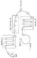
図1は、本発明の塗布膜の乾燥方法及び装置が適用される乾燥装置を組み込んだ塗布・乾燥ライン10の例を示す概念図である。図示されるように、塗布・乾燥ライン10は、主として、ロール状に巻回された帯状可撓性支持体12を送り出す送り出し装置(図示略)、帯状可撓性支持体12に塗布液を塗布する塗布手段16、帯状可撓性支持体12に塗布形成された塗布膜の塗布液中の溶媒を凝縮、回収させるドライヤ18、及び塗布・乾燥により製造された製品を巻き取る巻き取り装置(図示略)と、帯状可撓性支持体12が走行する搬送経路を形成する多数のガイドローラ22、22…とで形成される。また、必要に応じてドライヤ18の下流に、塗布膜を乾燥させる通風乾燥手段が設けられる。
FIG. 1 is a conceptual diagram showing an example of a coating / drying
そして、帯状可撓性支持体12に塗布形成された塗布膜は上側となり、ドライヤ18は帯状可撓性支持体12の上方に配され、かつ、後述する凝縮板20が帯状可撓性支持体12の走行方向に向かって上方に5度以上の所定角度αをもって傾斜するように配されている。
The coating film formed on the strip-shaped
また、図2、図3は、塗布膜の乾燥方法及び装置が適用される乾燥装置を組み込んだ塗布・乾燥ライン10の参考例を示す概念図である。
2 and 3 are conceptual diagrams showing a reference example of the coating / drying
図2、図3に示されるように、塗布・乾燥ライン10は、主として、ロール状に巻回された帯状可撓性支持体12を送り出す送り出し装置(図示略)、帯状可撓性支持体12に塗布液を塗布する塗布手段16、帯状可撓性支持体12に塗布形成された塗布膜の塗布液中の溶媒を凝縮、回収させるドライヤ18、及び塗布・乾燥により製造された製品を巻き取る巻き取り装置(図示略)と、帯状可撓性支持体12が走行する搬送経路を形成する多数のガイドローラ22、22…とで形成される。そして、この参考例においては、帯状可撓性支持体12に塗布形成された塗布膜は下側となり、ドライヤ18は帯状可撓性支持体12の下方に配置されている。
As shown in FIG. 2 and FIG. 3, the coating / drying
帯状可撓性支持体12としては、ポリエチレン、PET(ポリエチレンテレフタレート)、TAC(トリアセテート)等の樹脂フィルム、紙、金属箔等を使用できる。
As the belt-like
塗布手段16は、各種方式のものが使用できる。たとえば、スロット・ダイコータ、ワイヤーバーコータ、ロールコータ、グラビアコータ、スライドホッパ塗布方式、カーテン塗布方式、等が使用できる。 Various types of coating means 16 can be used. For example, a slot die coater, a wire bar coater, a roll coater, a gravure coater, a slide hopper coating method, a curtain coating method, or the like can be used.
なお、塗布手段16は、塗布面が水平方向に対して下側になるような構成であってもよいし、水平方向に対して上側になるような構成であってもよい。また、図1に示されるように水平方向に対して傾斜するような構成であってもよい。
The
図4は図1(本発明)、図2(参考例)及び図3(参考例)の乾燥装置を組み込んだ光学補償シートの製造ラインの例を示す概念図である。本発明の乾燥装置についても、同様に、塗布手段16の前段に除塵設備70を設置したり、帯状可撓性支持体12の表面に前処理等を施してもよい。ゴミ等の殆どない高い品質が求められる光学性フイルム等では、これらを同時に採用することで、高品質な塗布、乾燥膜を得ることができる。
FIG. 4 is a conceptual diagram showing an example of a production line of an optical compensation sheet incorporating the drying apparatus of FIG. 1 (the present invention), FIG. 2 (reference example), and FIG. 3 (reference example). Similarly, in the drying apparatus of the present invention, a
ドライヤ18は、帯状可撓性支持体12と所定距離をおいて平行に設けられる板状部材である凝縮板20と、凝縮板20の前後辺から下方に垂設される(図2、3では上方に立設される)側面板等とで構成される。これにより、塗布膜の塗布液中の溶媒が揮発した際に、揮発した溶媒が凝縮板20に凝縮し回収される構成となっている。
The
凝縮板20の溶媒を凝縮させる面に用いる材質は、金属、プラスチック、木材等、特に限定はされないが、塗布液中に有機溶剤が含まれる場合には、その有機溶剤に対して耐性のある材料を使用するか、又は表面にコーティングを施すことが望ましい。
The material used for the surface of the
ドライヤ18において、凝縮板20に凝縮した溶媒を回収させる手段は、たとえば、凝縮板20の凝縮面に溝を設け、毛管力を利用して溶媒を回収させる。溝の方向は、帯状可撓性支持体12の走行方向であってもよく、これに直交する方向であってもよい。凝縮板20が傾斜している場合には、溶媒を回収させやすい方向に溝を設ければよい。
In the
図6に示される例において、凝縮板20右端の下方には凝縮した溶媒を回収するための樋20aが設けられており、樋20aを経て溶媒が回収される。このように樋20aが設けられていれば、凝縮した溶媒の回収が容易に行える。樋20aを設ける位置は、図示の例に限られず、凝縮板20の構成に応じて、凝縮板20の下流側、側面等適宜な位置に設けられる。いずれにせよ、溶媒の流下により回収できる位置に設けていることが好ましい。
In the example shown in FIG. 6, a
なお、このような樋20aは、図8に示される凝縮板20を帯状可撓性支持体12の下方に配設した参考例においても設けられている。このように、樋20aを使用して凝縮した溶媒を回収する場合には、凝縮板20は水平面に対して5度以上の傾斜をもって配されていることが好ましい。
Such a
ドライヤ18に板状部材である凝縮板20を採用する構成以外に、同様な機能を奏する構成、たとえば、多孔板、網、簀の子、ロール等を使用する構成も採用できる。また、US5694701に示されるような回収装置と併用してもよい。
In addition to the configuration in which the condensing
ドライヤ18は、塗布液を塗布した直後の自然対流の発生による塗布膜の乾燥ムラを防止するため、塗布手段16のできるだけ近くに配設することが好ましい。具体的には、ドライヤ18の入口が塗布手段16から5m以内の位置になるように配設することが好ましく、ドライヤ18の入口が塗布手段16から2m以内の位置になるように配設することがより好ましく、ドライヤ18の入口が塗布手段16から0.7m以内の位置になるように配設することが最も好ましい。
The
同様の理由で、帯状可撓性支持体12の走行速度は、帯状可撓性支持体12が塗布手段16による塗布後30秒以内にドライヤ18に到達する速度であることが好ましく、帯状可撓性支持体12が塗布手段16による塗布後20秒以内にドライヤ18に到達する速度であることがより好ましい。
For the same reason, the running speed of the strip-shaped
塗布液の塗布量及び塗布膜厚さは、大きい程塗布膜内部での流動が起きやすいことよりムラが発生しやすいが、本発明によれば、塗布量及び塗布膜厚さが大きい場合でも十分な効果が得られる。塗布膜の厚さが0.001〜0.08mmであれば、ムラなくかつ効率よく乾燥することができる。 The larger the coating amount and the coating thickness of the coating solution, the more easily the unevenness occurs because the flow inside the coating film is more likely to occur. However, according to the present invention, even when the coating amount and the coating thickness are large, sufficient Effects can be obtained. If the thickness of the coating film is 0.001 to 0.08 mm, it can be dried uniformly and efficiently.
帯状可撓性支持体12の走行速度が大きすぎると、同伴風によって塗布膜近傍の境界層が乱され、塗布膜に悪影響を及ぼす。したがって、帯状可撓性支持体12の走行速度は1〜100m/分に設定することが好ましく、5〜80m/分に設定することがより好ましい。
If the running speed of the belt-like
塗布膜のムラは、乾燥初期で特に発生しやすいので、ドライヤ18が塗布液中の溶媒の10%以上を凝縮、回収し、残りの塗布液を通風乾燥手段で乾燥させることが好ましい。塗布液中の溶媒の何%を凝縮、回収させるかは、塗布膜の乾燥ムラへの影響、生産効率、等を総合的に判断して決定すればよい。
Since unevenness of the coating film is particularly likely to occur in the early stage of drying, it is preferable that the
塗布液中の溶媒の蒸発、凝縮を促進させるため、帯状可撓性支持体12及び/又は塗布膜を加熱するか、凝縮板20を冷却するか、又はその両手段方を採用することが好ましい。たとえば、ドライヤに冷却手段を配し、また、帯状可撓性支持体12を挟んでドライヤ18の反対側に加熱手段を配する。
In order to promote evaporation and condensation of the solvent in the coating solution, it is preferable to heat the belt-like
いずれの場合も、塗布膜の乾燥速度を制御するために、温度管理されていることが望ましい。凝縮板20は、温度コントロールできるようにし、冷却したい場合には、冷却するための設備を設置する必要がある。冷却には、冷媒等を使った水冷式の熱交換器方式のもの、風を使った空冷式、電気を用いた方式、たとえばペルチェ素子を使用した方式、等を用いることができる。
In any case, it is desirable that the temperature is controlled in order to control the drying rate of the coating film. The
帯状可撓性支持体12若しくは塗布膜、又はその両方を加熱したい場合には、反塗布膜側にヒータを配設して加熱することができる。また、昇温可能な搬送ロール(加熱ロール)を配設して加熱することもできる。その他、赤外線ヒータ、マイクロ波加熱手段等を用いて加熱してもよい。
When it is desired to heat the belt-like
帯状可撓性支持体12、塗布膜、凝縮板20の温度を決定する際、注意しなければならないのは、蒸発させた溶媒が凝縮板20以外の場所、たとえば、搬送ロールの表面等に結露しないようにしなければならないことである。このため、たとえば、凝縮板20以外の部分の温度を凝縮板20の温度よりも高くしておくことによりこの種の結露を回避することができる。
When determining the temperature of the belt-like
塗布膜の表面とドライヤ18の凝縮板20表面との距離(間隔)は、所望の塗布膜の乾燥速度を考慮した上で、適当な距離に調整する必要がある。距離を短くすると乾燥速度が上がる一方、設定した距離精度の影響を受けやすい。一方、距離を大きくすると乾燥速度が大幅に低下するのみならず、熱による自然対流が起きて乾燥ムラを引き起こす。塗布膜の表面とドライヤ18の凝縮板20表面との距離は、0.1〜200mmが好ましく、0.5〜100mmがより好ましい。
The distance (interval) between the surface of the coating film and the surface of the condensing
ドライヤ18は、必ずしも図1〜3に示されるような直線状である必要はなく、たとえば、円弧状のドライヤであってもよい。また、大きなドラムを設け、それにドライヤを配設してもよい。
The
必要に応じて使用される通風乾燥手段としては、従来技術として使用されている、非塗布面側をロールで支持し、塗布面側にエア・ノズルから風を吹いて乾燥させるローラ搬送ドライヤ方式、塗布面、非塗布面ともにエア・ノズルから風を吹いて、支持体を浮上させた状態、すなわち支持体がロール等に接触しないで乾燥させる非接触式のエアフローティングドライヤ方式、非接触式の乾燥方式の一種で、スペースを効率良く利用し、かつ効率良く乾燥させる弦巻き型の乾燥方式、等の乾燥装置が使用できる。いずれの方式の乾燥装置であっても、乾燥した空気を塗布膜の表面に供給して塗布膜を乾燥させる点では共通する。 As a ventilation drying means used as necessary, a roller transport dryer method used as a conventional technique, supporting a non-application surface side with a roll and blowing air from an air nozzle on the application surface side, Both the coated and non-coated surfaces are blown from the air nozzle to float the support, that is, the support is dried without contacting the roll, etc. Non-contact air floating dryer method, non-contact drying It is a kind of system, and a drying device such as a string winding type that efficiently uses space and efficiently dries can be used. Any type of drying apparatus is common in that dried air is supplied to the surface of the coating film to dry the coating film.
その他、本発明の塗布膜の乾燥方法及び装置が適用される乾燥装置を組み込んだ塗布・乾燥ライン10に使用されている送り出し装置、ガイドローラ22、巻き取り装置等には慣用の部材を使用しており、それらの説明は省略する。
In addition, conventional members are used for the feeding device, the
以上に詳述した本発明の塗布膜の乾燥装置によれば、塗布直後の塗布膜に発生するムラを抑制しかつ効率よく均一に塗布膜を乾燥できる。また、塗布、乾燥工程のレイアウトを大きく変更することなく、さらに、塗布液の物性や溶媒の種類等に制約されないので、塗布液処方手段の柔軟な設計が可能である。 According to the coating film drying apparatus of the present invention described in detail above, the coating film can be efficiently and uniformly dried while suppressing unevenness occurring in the coating film immediately after coating. In addition, the layout of the coating and drying process is not greatly changed, and further, the physical properties of the coating liquid and the type of solvent are not restricted, so that the coating liquid prescription means can be designed flexibly.
すなわち、たとえば既存の通風乾燥装置を含む塗布・乾燥装置の塗布部と通風乾燥装置との間に溶媒を凝縮・回収するドライヤを増設するだけで、本発明の装置と同様の形態とでき、その結果、低コストで装置改造ができる。 That is, for example, by simply adding a dryer for condensing and recovering the solvent between the coating unit of the coating / drying apparatus including the existing ventilation drying apparatus and the ventilation drying apparatus, the configuration similar to that of the apparatus of the present invention can be obtained. As a result, the device can be modified at low cost.
また、本発明の塗布膜の乾燥装置によれば、省エネルギー化、コストダウンにも効果がある。すなわち、塗布・乾燥ラインで発生する蒸発気体のうち水以外の溶媒はそのまま大気へ放出できないので、蒸発気体を液化して回収する必要があり、そのための溶剤ガス回収設備が必要である。ところが、塗布・乾燥ライン10では、塗布液の一部を凝縮・回収するドライヤにより溶媒を液体の状態で直接回収できるため、溶剤ガス回収設備の負荷を減らすことができる。
Further, the coating film drying apparatus of the present invention is effective in energy saving and cost reduction. That is, since the solvent other than water cannot be released into the atmosphere as it is in the evaporation gas generated in the coating / drying line, the evaporation gas needs to be liquefied and recovered, and a solvent gas recovery facility for that purpose is required. However, in the coating / drying
また、本発明の塗布膜の乾燥装置を用いると、乾燥初期において非常に均一な乾燥が可能なため、次のような予期しなかった効果が得られることがわかった。すなわち、従来の通風乾燥装置では、塗布膜を乱す影響を完全には抑えられないため、塗布膜内に流動を生じていたが、本発明の装置を用いると、それらの流動を防止でき、また、乾燥中に形成される塗布膜中の高分子、粒子のネットワークの構造を非常に細かく、しかも均一に形成できることがわかった。 Further, it was found that when the coating film drying apparatus of the present invention was used, extremely uniform drying was possible in the initial stage of drying, and the following unexpected effects were obtained. That is, in the conventional ventilation drying apparatus, since the influence that disturbs the coating film cannot be completely suppressed, the flow is generated in the coating film. However, when the apparatus of the present invention is used, the flow can be prevented, and It has been found that the polymer and particle network structure in the coating film formed during drying can be formed very finely and uniformly.
これにより、単に塗布膜を均一に乾燥させるだけのみならず、塗布膜の構造が細かくなることにより、たとえば、光学フイルムの場合、新たな付加機能を追加できることにもつながる。 As a result, the coating film is not only dried uniformly, but also the structure of the coating film becomes finer. For example, in the case of an optical film, a new additional function can be added.
また、本発明の塗布膜の乾燥装置は、たとえば、ナノ粒子等が含まれる機能性膜の乾燥等にも非常に適しているといえる。 Moreover, it can be said that the drying apparatus of the coating film of this invention is very suitable for the drying of the functional film | membrane containing a nanoparticle etc., for example.
本発明の塗布膜の乾燥装置は、塗布液に高分子や粒子等の固形分が溶解又は分散されたものに適用した場合でも、同様の効果が得られる。むしろ、粒子等が含まれる系では、乾燥ムラの発生が塗布膜中の粒子の分散分布にも大きく影響する。したがって、この系に本システムを使用することは好ましい。 Even when the coating film drying apparatus of the present invention is applied to a coating solution in which a solid content such as a polymer or particles is dissolved or dispersed, the same effect can be obtained. Rather, in a system containing particles or the like, the occurrence of drying unevenness greatly affects the dispersion distribution of particles in the coating film. Therefore, it is preferable to use this system in this system.
[実施例1]
図4に示される光学補償シートの製造ラインにおける塗布層の乾燥工程に、塗布液中の溶媒を凝縮、回収させるドライヤ18を配設して、光学補償シートを製造する上での好適なドライヤの構造及び溶媒の凝縮、回収条件を検討した。
[Example 1]
A
図4に示されるように、光学補償シートの製造ラインは、たとえば下記の工程により行われる。
1)透明フィルム12の送出工程14;
2)透明フィルムの表面に配向膜形成用樹脂を含む塗布液を塗布、乾燥する配向膜形成用樹脂層の形成工程52;
3)表面に配向膜形成用樹層が形成された透明フィルム上に、樹脂層の表面にラビング処理を施し透明フィルム上に配向膜を形成するラビング工程54;
4)液晶性ディスコティック化合物を含む塗布液を、配向膜上に塗布する液晶性ディスコティック化合物の塗布工程16;
5)該塗布膜を乾燥して該塗布膜中の溶媒を蒸発させる乾燥工程18;
6)該塗布膜をディスコティックネマティック相形成温度に加熱して、ディスコティックネマティック相の液晶層を形成する液晶層形成工程58;
7)該液晶層を固化する(すなわち、液晶層形成後急冷して固化させるか、又は、架橋性官能基を有する液晶性ディスコティック化合物を使用した場合、液晶層を光照射(又は加熱)により架橋させる)工程60;
8)該配向膜及び液晶層が形成された透明フィルムを巻き取る巻取り工程24。
As shown in FIG. 4, the optical compensation sheet production line is performed, for example, by the following steps.
1)
2) A forming
3) A rubbing
4) A liquid crystal discotic
5) A drying
6) A liquid crystal
7) The liquid crystal layer is solidified (that is, solidified by rapid cooling after forming the liquid crystal layer, or when a liquid crystalline discotic compound having a crosslinkable functional group is used, the liquid crystal layer is irradiated by light irradiation (or heating). Crosslinking)
8) A winding
なお、図4において、50は乾燥ゾーンを、64は検査装置を、66は保護フィルムを、68はラミネート機を、70は徐塵設備をそれぞれ示す。 In FIG. 4, 50 indicates a drying zone, 64 indicates an inspection device, 66 indicates a protective film, 68 indicates a laminating machine, and 70 indicates a slow dust facility.
光学補償シートの製造方法は、図4に示されるように長尺状透明フィルムを送り出す工程から、得られた光学補償シートを巻き取る工程まで一貫して連続的に行なった。トリアセチルセルロース(フジタック、富士写真フィルム(株)製、厚さ:100μm、幅:500mm)の長尺状のフィルムの一方の側に、長鎖アルキル変成ポバール(MP−203、クラレ(株)製)5重量%溶液を塗布し、90℃で4分間乾燥させた後、ラビング処理を行って膜厚2.0μmの配向膜形成用樹脂層を形成した。フィルムの搬送速度は、20m/分であった。 As shown in FIG. 4, the method for producing the optical compensation sheet was continuously performed continuously from the step of feeding the long transparent film to the step of winding up the obtained optical compensation sheet. On one side of a long film of triacetylcellulose (Fujitack, manufactured by Fuji Photo Film Co., Ltd., thickness: 100 μm, width: 500 mm), a long-chain alkyl-modified poval (MP-203, manufactured by Kuraray Co., Ltd.) ) A 5 wt% solution was applied and dried at 90 ° C. for 4 minutes, followed by rubbing to form an alignment film forming resin layer having a thickness of 2.0 μm. The conveyance speed of the film was 20 m / min.
上記トリアセチルセルロースフィルムは、フィルム面内の直交する二方向の屈折率をnx、ny、厚さ方向の屈折率をnz、そしてフィルムの厚さをdとしたとき、(nx−ny)×d=16nm、{(nx−ny)/2−nz}×d=75nmであった。また、上記配向膜形成用樹脂層の形成は、塗布・乾燥装置を用いて行なった。 The triacetyl cellulose film has (nx−ny) × d, where nx and ny are the refractive indexes in two orthogonal directions in the film plane, nz is the refractive index in the thickness direction, and d is the thickness of the film. = 16 nm, {(nx-ny) / 2-nz} × d = 75 nm. The alignment layer forming resin layer was formed using a coating / drying apparatus.
続いて、得られた樹脂層を有するフィルムを、連続して20m/分で搬送しながら、樹脂層表面にラビング処理を施した。ラビング処理は、ラビングローラの回転数を300rpmにて行い、次いで得られた配向膜の除塵を行った。 Subsequently, the surface of the resin layer was rubbed while the film having the obtained resin layer was continuously conveyed at 20 m / min. In the rubbing treatment, the rubbing roller was rotated at 300 rpm, and then the resulting alignment film was dedusted.
次いで、得られた配向膜を有するフィルムを、連続して20m/分の速度で搬送しながら、配向膜上に、ディスコティック化合物TE−8の(3)とTE−8の(5)の重量比で4:1の混合物に、光重合開始剤(イルガキュア907、日本チバガイギー(株)製)を上記混合物に対して1重量%添加した混合物の10重量%メチルエチルケトン溶液(塗布液)を、ワイヤーバー塗布機にて、塗布速度を20m/分、塗布量を5cc/m2で塗布し、次いで乾燥及び加熱ゾーンを通過させた。乾燥ゾーンには風を送り、加熱ゾーンは130℃に調整した。塗布後3秒後に乾燥ゾーンに入り、3秒後に加熱ゾーンに入った。加熱ゾーンは約3分で通過した。 Next, the weight of the discotic compound TE-8 (3) and the weight of TE-8 (5) is transferred onto the alignment film while continuously transporting the obtained film having the alignment film at a speed of 20 m / min. A 10% by weight methyl ethyl ketone solution (coating solution) of a mixture obtained by adding 1% by weight of a photopolymerization initiator (Irgacure 907, manufactured by Nippon Ciba Geigy Co., Ltd.) to the above mixture in a ratio of 4: 1 by Using a coating machine, coating was performed at a coating speed of 20 m / min and a coating amount of 5 cc / m 2 , and then passed through a drying and heating zone. Air was sent to the drying zone, and the heating zone was adjusted to 130 ° C. After 3 seconds from coating, it entered the drying zone, and after 3 seconds, it entered the heating zone. The heating zone passed in about 3 minutes.
続いて、この配向膜及び液晶層が塗布されフィルムを、連続して20m/分で搬送しながら、液晶層の表面に紫外線ランプにより紫外線を照射した。すなわち、上記加熱ゾーンを通過したフィルムは、紫外線照射装置(紫外線ランプ:出力160W/cm、発光長1.6m)により、照度600mWの紫外線を4秒間照射し、液晶層を架橋させた。 Subsequently, the alignment film and the liquid crystal layer were applied, and the film was continuously conveyed at 20 m / min, and the surface of the liquid crystal layer was irradiated with ultraviolet rays by an ultraviolet lamp. That is, the film that passed through the heating zone was irradiated with ultraviolet rays having an illuminance of 600 mW for 4 seconds by an ultraviolet irradiation device (ultraviolet lamp: output 160 W / cm, emission length 1.6 m) to crosslink the liquid crystal layer.
これに対し、比較例として、図5に示されるように、塗布手段16により、帯状可撓性支持体12の下面に塗布液を塗布し、その後に帯状可撓性支持体12をガイドローラ22、22、22で反転し、塗布液の塗布面が上面になるようにしてドライヤ18に入る構成を採用した。その他の構成は実施例と同一とした。
On the other hand, as a comparative example, as shown in FIG. 5, the coating liquid is applied to the lower surface of the strip-shaped
上記の工程により、下記の実施例、参考例及び比較例の条件で試験を行った。以下に、その条件及び結果を記す。 By the above steps, the test was conducted under the conditions of the following examples, reference examples and comparative examples. The conditions and results are described below.
(実施例)
ドライヤ18周辺の構成は図1に示される配置とした。ドライヤ18には、帯状可撓性支持体12の上方に、帯状可撓性支持体12と所定距離をおいて略平行に板状部材である凝縮板20を配設した。傾斜角度αは15度とした。
(Example)
The configuration around the
ヒータ温度を85℃、凝縮板温度を25℃とした。ドライヤ18は、入口が塗布手段16から500mmの位置となるように配した。塗布膜の表面とドライヤ18の凝縮板20表面との距離は1mmとした。
The heater temperature was 85 ° C. and the condenser plate temperature was 25 ° C. The
その結果、塗布膜品質に問題は生じなかった。 As a result, no problem occurred in the coating film quality.
(参考例)
ドライヤ18周辺の構成は図2に示される配置とした。ドライヤ18には、帯状可撓性支持体12の下方に、帯状可撓性支持体12と所定距離をおいて略平行に板状部材である凝縮板20を配設した。
(Reference example)
The configuration around the
ヒータ温度を85℃、凝縮板温度を25℃とした。ドライヤ18は、入口が塗布手段16から500mmの位置となるように配した。塗布膜の表面とドライヤ18の凝縮板20表面との距離は1mmとした。
The heater temperature was 85 ° C. and the condenser plate temperature was 25 ° C. The
その結果、塗布膜品質に問題は生じなかった。 As a result, no problem occurred in the coating film quality.
(比較例)
ドライヤ18周辺の構成は図2に示される配置とした。ドライヤ18には、帯状可撓性支持体12の下方に、帯状可撓性支持体12と所定距離をおいて略平行に板状部材である凝縮板20を配設した。
(Comparative example)
The configuration around the
ヒータ温度を85℃、凝縮板温度を25℃とした。ドライヤ18は、入口が塗布手段16から10mの位置となるように配した。すなわち、ドライヤ18の配設位置は塗布直後の走行位置ではなく、塗布手段16から所定距離離した位置とした。塗布膜の表面とドライヤ18の凝縮板20表面との距離は1mmとした。
The heater temperature was 85 ° C. and the condenser plate temperature was 25 ° C. The
その結果、塗布膜には乾燥ムラが生じ、また配向不良も発生した。 As a result, drying unevenness occurred in the coating film, and alignment failure occurred.
[実施例2]
感光用セルロースアセテートフィルムの製造ラインにおける下塗り塗布後の乾燥工程において、本発明における塗布液中の溶媒を凝縮、回収させるドライヤを配設した場合と、従来の通風乾燥タイプの乾燥器を配設した場合とを比較した。
[Example 2]
In the drying process after the undercoat coating in the photosensitive cellulose acetate film production line, a dryer for condensing and recovering the solvent in the coating liquid in the present invention is disposed, and a conventional ventilation drying type dryer is disposed. The case was compared.
図6に示される、本発明におけるドライヤを使用した製造ラインにおいて、セルロースアセテートドープが流延ダイから流延ドラム面上に流延され、それによって形成されたフィルムが剥ぎ取りローラで剥ぎ取られ、前乾燥工程のロール間を走行する間に熱風により乾燥される。 In the production line using the dryer of the present invention shown in FIG. 6, the cellulose acetate dope is cast from the casting die onto the casting drum surface, and the film formed thereby is peeled off by the peeling roller. It is dried with hot air while traveling between the rolls in the pre-drying step.
次いで、写真感光材料用下塗りを行い、さらにドライヤ18で乾燥させる。残留溶媒が約10%以下となった時点で、幅規制装置(図示略)に導き幅方向に2〜6%延伸させ、さらに緊張状態のまま冷却した後に巻き取られる。
Next, an undercoat for a photographic light-sensitive material is applied and further dried with a
ドライヤ18の凝縮板20は2個のゾーンに分割した。また、2個の凝縮板20は、いずれも走行方向の下流側が塗布膜から離れるような傾斜角度をもって配した。塗布膜の表面とドライヤ18の凝縮板20表面との距離は、走行方向の下流側に向かって、上流側の凝縮板20の入口側で0.8mm、出口側で2mmとし、下流側の凝縮板20の入口側で0.8mm、出口側で2mmとした。
The
また、上流側の凝縮板20の長さを2m、下流側の凝縮板20の長さを4mとした。凝縮板20の設定温度は、いずれも15℃とした。
Further, the length of the
製造した製品の表面性状は良好であった。 The surface quality of the manufactured product was good.
図7に示される、従来の通風乾燥タイプの乾燥器を使用した製造ラインにおいて、下塗り塗布乾燥工程の装置は、通常の通風乾燥タイプの乾燥器である。製造ラインのその他の部分は図6に示される構成同様であり、説明を省略する。 In the production line using the conventional ventilation drying type dryer shown in FIG. 7, the apparatus of the undercoat coating drying process is a normal ventilation drying type dryer. The other parts of the production line are the same as the configuration shown in FIG.
製造した製品の表面性状は、下塗りでの乾燥ムラを生じ不良となった。 The surface properties of the manufactured product were poor due to uneven drying in the undercoat.
10…塗布・乾燥ライン、12…帯状可撓性支持体、14…送り出し装置、16…塗布手段、18…ドライヤ、20…凝縮板、22…ガイドローラ、24…巻き取り装置
DESCRIPTION OF
Claims (17)
前記ドライヤには、前記帯状可撓性支持体の上方に、帯状可撓性支持体と所定距離をおいて略平行に板状部材である凝縮板を配設するとともに、該凝縮板を帯状可撓性支持体の走行方向に向かって上方に5度以上傾斜させ、
前記帯状可撓性支持体の走行速度は、前記帯状可撓性支持体が前記塗布手段により塗布後30秒以内に前記ドライヤに到達する速度であることを特徴とする塗布膜の乾燥方法。 In the method for drying a coating film, a coating liquid is applied to a traveling belt-like flexible support by a coating means, and a dryer for condensing and collecting the solvent in the coating liquid is disposed at a traveling position immediately after coating.
A condensing plate, which is a plate-like member, is disposed above the belt-like flexible support above the belt-like flexible support at a predetermined distance and in parallel with the dryer. Inclined upward by 5 degrees or more toward the running direction of the flexible support,
The traveling speed of the strip-shaped flexible support is a speed at which the strip-shaped flexible support reaches the dryer within 30 seconds after coating by the coating means.
前記ドライヤには、前記帯状可撓性支持体の上方に、帯状可撓性支持体と所定距離をおいて略平行に、板状部材である凝縮板が配設されているとともに、該凝縮板が帯状可撓性支持体の走行方向に向かって上方に5度以上の傾斜角度をもって配設されており、
前記帯状可撓性支持体の走行速度が、前記帯状可撓性が前記塗布手段による塗布後30秒以内に前記ドライヤに到達する速度であることを特徴とする塗布膜の乾燥装置。 In an apparatus for drying a coating film, which is disposed in a subsequent stage following the coating means for coating the coating liquid on the traveling belt-like flexible support, and has a dryer for condensing and collecting the solvent in the coated coating solution.
The dryer is provided with a condensing plate, which is a plate-like member, at a predetermined distance above and in parallel with the strip-shaped flexible support above the strip-shaped flexible support. Is disposed at an inclination angle of 5 degrees or more upward in the running direction of the belt-like flexible support,
An apparatus for drying a coating film, wherein the belt-like flexible support travels at a speed at which the belt-like flexibility reaches the dryer within 30 seconds after coating by the coating means.
Priority Applications (1)
| Application Number | Priority Date | Filing Date | Title |
|---|---|---|---|
| JP2007057722A JP2007175703A (en) | 2001-09-27 | 2007-03-07 | Method and apparatus for drying coating film |
Applications Claiming Priority (2)
| Application Number | Priority Date | Filing Date | Title |
|---|---|---|---|
| JP2001298405 | 2001-09-27 | ||
| JP2007057722A JP2007175703A (en) | 2001-09-27 | 2007-03-07 | Method and apparatus for drying coating film |
Related Parent Applications (1)
| Application Number | Title | Priority Date | Filing Date |
|---|---|---|---|
| JP2001389714A Division JP3968505B2 (en) | 2001-09-27 | 2001-12-21 | Coating film drying method and apparatus |
Publications (1)
| Publication Number | Publication Date |
|---|---|
| JP2007175703A true JP2007175703A (en) | 2007-07-12 |
Family
ID=38301412
Family Applications (1)
| Application Number | Title | Priority Date | Filing Date |
|---|---|---|---|
| JP2007057722A Pending JP2007175703A (en) | 2001-09-27 | 2007-03-07 | Method and apparatus for drying coating film |
Country Status (1)
| Country | Link |
|---|---|
| JP (1) | JP2007175703A (en) |
Cited By (9)
| Publication number | Priority date | Publication date | Assignee | Title |
|---|---|---|---|---|
| JP2011069567A (en) * | 2009-09-28 | 2011-04-07 | Komori Corp | Drying device for sheet-shaped object |
| JP2011082059A (en) * | 2009-10-08 | 2011-04-21 | Nissan Motor Co Ltd | Electrode drying device and electrode drying method |
| CN103182357A (en) * | 2011-12-30 | 2013-07-03 | 北京星和众工设备技术股份有限公司 | Roller coater coating thickness automatic adjusting method |
| JP2015171819A (en) * | 2015-04-30 | 2015-10-01 | 日東電工株式会社 | Method for manufacturing adhesive layer-carrying optical film |
| US20170141310A1 (en) * | 2015-11-16 | 2017-05-18 | Kateeva, Inc | Systems and Methods for Thermal Processing of a Substrate |
| US10005257B2 (en) | 2012-06-08 | 2018-06-26 | Nitto Denko Corporation | Method for producing pressure-sensitive adhesive layer-carrying optical film |
| US10468279B2 (en) | 2013-12-26 | 2019-11-05 | Kateeva, Inc. | Apparatus and techniques for thermal treatment of electronic devices |
| US11338319B2 (en) | 2014-04-30 | 2022-05-24 | Kateeva, Inc. | Gas cushion apparatus and techniques for substrate coating |
| US11633968B2 (en) | 2008-06-13 | 2023-04-25 | Kateeva, Inc. | Low-particle gas enclosure systems and methods |
-
2007
- 2007-03-07 JP JP2007057722A patent/JP2007175703A/en active Pending
Cited By (13)
| Publication number | Priority date | Publication date | Assignee | Title |
|---|---|---|---|---|
| US11633968B2 (en) | 2008-06-13 | 2023-04-25 | Kateeva, Inc. | Low-particle gas enclosure systems and methods |
| CN102029779A (en) * | 2009-09-28 | 2011-04-27 | 小森公司 | Flap-like drier |
| JP2011069567A (en) * | 2009-09-28 | 2011-04-07 | Komori Corp | Drying device for sheet-shaped object |
| JP2011082059A (en) * | 2009-10-08 | 2011-04-21 | Nissan Motor Co Ltd | Electrode drying device and electrode drying method |
| CN103182357A (en) * | 2011-12-30 | 2013-07-03 | 北京星和众工设备技术股份有限公司 | Roller coater coating thickness automatic adjusting method |
| US10005257B2 (en) | 2012-06-08 | 2018-06-26 | Nitto Denko Corporation | Method for producing pressure-sensitive adhesive layer-carrying optical film |
| US10468279B2 (en) | 2013-12-26 | 2019-11-05 | Kateeva, Inc. | Apparatus and techniques for thermal treatment of electronic devices |
| US11107712B2 (en) | 2013-12-26 | 2021-08-31 | Kateeva, Inc. | Techniques for thermal treatment of electronic devices |
| US11338319B2 (en) | 2014-04-30 | 2022-05-24 | Kateeva, Inc. | Gas cushion apparatus and techniques for substrate coating |
| JP2015171819A (en) * | 2015-04-30 | 2015-10-01 | 日東電工株式会社 | Method for manufacturing adhesive layer-carrying optical film |
| WO2017087337A1 (en) * | 2015-11-16 | 2017-05-26 | Kateeva, Inc. | Systems and methods for thermal processing of a substrate |
| US10115900B2 (en) * | 2015-11-16 | 2018-10-30 | Kateeva, Inc. | Systems and methods for thermal processing of a substrate |
| US20170141310A1 (en) * | 2015-11-16 | 2017-05-18 | Kateeva, Inc | Systems and Methods for Thermal Processing of a Substrate |
Similar Documents
| Publication | Publication Date | Title |
|---|---|---|
| JP4951301B2 (en) | Optical film drying method and apparatus, and optical film manufacturing method | |
| JP2007175703A (en) | Method and apparatus for drying coating film | |
| US8828501B1 (en) | Drying method and drying apparatus for coating layer | |
| JP5222333B2 (en) | Coating film drying method and apparatus | |
| JP4901395B2 (en) | Drying method of coating film | |
| JP5189424B2 (en) | Drying method of coating film | |
| JP4193388B2 (en) | Drying method of coating film | |
| JP4631242B2 (en) | Coating film drying method and apparatus | |
| JP2003170102A (en) | Method and apparatus drying coating film | |
| JP4004429B2 (en) | Coating film drying method and apparatus | |
| JP4601909B2 (en) | Coating film drying method and apparatus | |
| JP3968505B2 (en) | Coating film drying method and apparatus | |
| JP4699660B2 (en) | Coating film drying method and apparatus | |
| JP2003329833A (en) | Method and device for manufacturing optical compensation sheet | |
| JP5147291B2 (en) | Drying apparatus and optical film manufacturing method | |
| JP2010101595A (en) | Dryer and method of manufacturing resin film | |
| JP4934111B2 (en) | Drying method of coating film | |
| JP2009006248A (en) | Method and apparatus for drying coating film | |
| JP4920737B2 (en) | Drying method of coating film | |
| JP4178300B2 (en) | Coating film drying method and optical functional film | |
| JP2010069443A (en) | Apparatus for drying coating film and optical film formed by the same | |
| JP2001096212A (en) | Coating method and device therefor | |
| JP2003251251A (en) | Drying apparatus, drying method and method for manufacturing image forming material by using these apparatus and method | |
| JP2009213976A (en) | Coating apparatus | |
| JP2003103211A (en) | Coating and drying method and equipment |
Legal Events
| Date | Code | Title | Description |
|---|---|---|---|
| A131 | Notification of reasons for refusal |
Free format text: JAPANESE INTERMEDIATE CODE: A132 Effective date: 20080318 |
|
| A02 | Decision of refusal |
Free format text: JAPANESE INTERMEDIATE CODE: A02 Effective date: 20090114 |