JP2007174460A - Medium to be recorded, image object and image forming method - Google Patents
Medium to be recorded, image object and image forming method Download PDFInfo
- Publication number
- JP2007174460A JP2007174460A JP2005371465A JP2005371465A JP2007174460A JP 2007174460 A JP2007174460 A JP 2007174460A JP 2005371465 A JP2005371465 A JP 2005371465A JP 2005371465 A JP2005371465 A JP 2005371465A JP 2007174460 A JP2007174460 A JP 2007174460A
- Authority
- JP
- Japan
- Prior art keywords
- recording medium
- ink
- image
- recording
- present
- Prior art date
- Legal status (The legal status is an assumption and is not a legal conclusion. Google has not performed a legal analysis and makes no representation as to the accuracy of the status listed.)
- Withdrawn
Links
Images


Classifications
-
- B—PERFORMING OPERATIONS; TRANSPORTING
- B41—PRINTING; LINING MACHINES; TYPEWRITERS; STAMPS
- B41J—TYPEWRITERS; SELECTIVE PRINTING MECHANISMS, i.e. MECHANISMS PRINTING OTHERWISE THAN FROM A FORME; CORRECTION OF TYPOGRAPHICAL ERRORS
- B41J3/00—Typewriters or selective printing or marking mechanisms characterised by the purpose for which they are constructed
- B41J3/407—Typewriters or selective printing or marking mechanisms characterised by the purpose for which they are constructed for marking on special material
-
- G—PHYSICS
- G06—COMPUTING; CALCULATING OR COUNTING
- G06K—GRAPHICAL DATA READING; PRESENTATION OF DATA; RECORD CARRIERS; HANDLING RECORD CARRIERS
- G06K17/00—Methods or arrangements for effecting co-operative working between equipments covered by two or more of main groups G06K1/00 - G06K15/00, e.g. automatic card files incorporating conveying and reading operations
- G06K17/0022—Methods or arrangements for effecting co-operative working between equipments covered by two or more of main groups G06K1/00 - G06K15/00, e.g. automatic card files incorporating conveying and reading operations arrangements or provisious for transferring data to distant stations, e.g. from a sensing device
- G06K17/0025—Methods or arrangements for effecting co-operative working between equipments covered by two or more of main groups G06K1/00 - G06K15/00, e.g. automatic card files incorporating conveying and reading operations arrangements or provisious for transferring data to distant stations, e.g. from a sensing device the arrangement consisting of a wireless interrogation device in combination with a device for optically marking the record carrier
-
- G—PHYSICS
- G06—COMPUTING; CALCULATING OR COUNTING
- G06K—GRAPHICAL DATA READING; PRESENTATION OF DATA; RECORD CARRIERS; HANDLING RECORD CARRIERS
- G06K19/00—Record carriers for use with machines and with at least a part designed to carry digital markings
- G06K19/06—Record carriers for use with machines and with at least a part designed to carry digital markings characterised by the kind of the digital marking, e.g. shape, nature, code
- G06K19/067—Record carriers with conductive marks, printed circuits or semiconductor circuit elements, e.g. credit or identity cards also with resonating or responding marks without active components
- G06K19/07—Record carriers with conductive marks, printed circuits or semiconductor circuit elements, e.g. credit or identity cards also with resonating or responding marks without active components with integrated circuit chips
- G06K19/077—Constructional details, e.g. mounting of circuits in the carrier
- G06K19/07749—Constructional details, e.g. mounting of circuits in the carrier the record carrier being capable of non-contact communication, e.g. constructional details of the antenna of a non-contact smart card
- G06K19/07758—Constructional details, e.g. mounting of circuits in the carrier the record carrier being capable of non-contact communication, e.g. constructional details of the antenna of a non-contact smart card arrangements for adhering the record carrier to further objects or living beings, functioning as an identification tag
Abstract
Description
本発明は、バゲージタグ等の識別票として好適な、RF−ID(Radio Frequency Identification)等非接触で情報の書き込み、読み出しが可能な素子を内蔵する被記録媒体に関わり、更に詳しくは上記被記録媒体へ画像を形成させた画像物、及び上記被記録媒体への画像形成方法に関する。 The present invention relates to a recording medium containing an element capable of writing and reading information in a non-contact manner, such as RF-ID (Radio Frequency Identification), which is suitable as an identification tag for baggage tags and the like. The present invention relates to an image formed with an image and a method for forming an image on the recording medium.
従来、空港における航空荷物は、バゲージタグの表示を視覚またはバーコード等によって認識して仕分け、発送することがおこなわれている。また、降機空港において搭乗者が荷物を受け取る際も目視により認識することで特別の自動化は図られていない。しかし、これらには以下のような問題がある。
(1)航空荷物は、搭乗時期の前に空港に搭乗者とは別に送られてくる場合があり仕分けや保管が煩雑となる。
(2)航空荷物の表示の認識を人手やバーコードで行うのは時間がかかり誤りを生じ易い。そのため行き先や便を間違える事故が頻発する。
(3)認識した表示のとおりに航空荷物を仕分け、搬送するのは人手によることになりその労力が過大である。
(4)降機空港において搭乗者が荷物を自分で確認して取り上げるのは労力を必要とし、年配者や体力の弱い者には耐えられない負担となる。
(5)同様に、目視により判断して荷物を取り上げるので他人が間違ってあるいは故意に荷物を持って行ってしまうことがある。
(6)いつまでも荷物が出てこない場合は事故なのか誰かが持って行ってしまったのか分からず不安になる。
Conventionally, air baggage at an airport is sorted and shipped by visually recognizing the display of a baggage tag or by a bar code or the like. In addition, special automation has not been achieved by visually recognizing when a passenger receives a baggage at a disembarking airport. However, these have the following problems.
(1) Air baggage may be sent to the airport separately from the passenger before the boarding time, and sorting and storage becomes complicated.
(2) It is time consuming and error-prone to recognize air baggage display manually or with a barcode. As a result, accidents involving wrong destinations and flights occur frequently.
(3) Sorting and transporting air baggage according to the recognized display is done manually, which is excessive.
(4) It is necessary for the passenger to check and pick up the baggage by himself at the disembarking airport, which is a burden that cannot be tolerated by the elderly or those with weak physical strength.
(5) Similarly, since the baggage is picked up by visual judgment, another person may carry the baggage by mistake or intentionally.
(6) If your luggage doesn't come out indefinitely, you're worried because you don't know if it was an accident or someone took it with you.
このような問題を解決するために、最近ではバゲージタグにRF−ID(Radio Frequency Identification)等非接触で情報の書き込み、読み出しが可能な無線通信素子を内蔵するバゲージタグとそれを利用したシステムが注目されている。 In order to solve such a problem, recently, a baggage tag including a wireless communication element capable of writing and reading information in a contactless manner such as RF-ID (Radio Frequency Identification) and the like and a system using the baggage tag attract attention. ing.
例えば、特開2001−240218、特開2001−243502では、バゲージタグに電子的に処理可能で書換え可能な非接触ICとバゲージタグの表示内容を可視的に書換え可能なリライト表示部を設けたバゲージタグとそれを利用したシステムを開示している。 For example, in Japanese Patent Laid-Open No. 2001-240218 and Japanese Patent Laid-Open No. 2001-243502, a baggage tag provided with a non-contact IC that can be electronically processed and rewritten on a baggage tag, and a rewrite display unit that can visually rewrite display contents of the baggage tag, and A system that uses the system is disclosed.
しかしながら、開示されているこのバゲージタグは、感熱方式で記録する為に、以下の問題を抱えていた。
ICが搭載されている凸凹においては、文字のかすれや欠け等が生じしまう。
IC部を避けて画像表示部を設ける必要があり、画像表示部の領域に制限があった。
IC部が搭載されていない例え表面が平滑であったとしても、部分的に熱伝導性が異なる為に良好な印字特性を得ることは困難であった。
バゲージタグを荷物の識別票として使用する際、IC部がタグの丁度彎曲部に位置している為に、荷物の物流時に容易に取り外される危険性がある。
また、IC部がタグの丁度彎曲部に位置している為に、荷物の物流時の機械的ストレスに弱い。
However, the disclosed baggage tag has the following problems in order to record by the thermal method.
In the unevenness on which the IC is mounted, characters are blurred or missing.
It is necessary to provide an image display unit avoiding the IC unit, and there is a limitation on the area of the image display unit.
Even if the surface on which the IC part is not mounted is smooth, it is difficult to obtain good printing characteristics due to partial differences in thermal conductivity.
When the baggage tag is used as a baggage identification tag, there is a risk that the IC unit is located at the curved portion of the tag, so that the baggage tag can be easily removed during the distribution of the baggage.
In addition, since the IC part is located just in the bent part of the tag, it is vulnerable to mechanical stress at the time of goods distribution.
本発明はこのような問題に鑑みてなされたものであって、即ち本発明は、内蔵する素子(例えば無線通信素子)の信頼性に優れかつ、画像表示部の画像適性に優れた被記録媒体の提供を目的とする。 The present invention has been made in view of such a problem, that is, the present invention is a recording medium excellent in the reliability of a built-in element (for example, a wireless communication element) and excellent in image suitability of an image display unit. The purpose is to provide.
又、本発明は、前述の被記録媒体に対して非接触で情報の読取り、情報の書き込み及び、非接触で記録可能な画像物及び、画像物形成方法の提供を目的としている。 Another object of the present invention is to provide an image object capable of reading information in a non-contact manner, writing information, and recording in a non-contact manner, and an image object forming method.
又、本発明は、ICが搭載されている凸凹においては、文字のかすれや欠け等が生じにくい用被記録媒体の提供を目的とする。
又、本発明の他の目的は、IC部の位置に関係無く画像表示部を設けることが出来る被記録媒体の提供を目的とする。
Another object of the present invention is to provide a recording medium for use in which unevenness and chipping of characters are less likely to occur in unevenness on which an IC is mounted.
Another object of the present invention is to provide a recording medium in which an image display unit can be provided regardless of the position of the IC unit.
又、本発明の他の目的は、部分的に熱伝導性が異なることによる良好な印字特性を得ることは困難であった事を改善する被記録媒体の提供を目的とする。 Another object of the present invention is to provide a recording medium that improves that it has been difficult to obtain good printing characteristics due to partial differences in thermal conductivity.
又、本発明の他の目的は、バゲージタグを荷物の識別票として使用する際、識別票を湾曲させてもICタグ部がそれにより問題が発生しないような被記録媒体の提供することを目的とする。 Another object of the present invention is to provide a recording medium in which the IC tag portion does not cause a problem even when the identification tag is curved when the baggage tag is used as an identification tag for a package. To do.
又、本発明の他の目的は、IC付きの被記録媒体の機械的なストレスに強いICタグ付き被記録媒体の提供を目的とする。 Another object of the present invention is to provide a recording medium with an IC tag that is resistant to mechanical stress of the recording medium with an IC.
上記目的を達成する為、本発明は、基材上に外部から情報のアクセス可能な素子と画像記録部を具備し、貼り合わせて使用する被記録媒体であって、該素子を被記録媒体の貼り合わせ位置に設けた事を特徴とする。
また本発明の他の目的は、前記被記録媒体の貼り合わせ位置が他の媒体との張り合わせ位置にしたことを特徴とする。
また本発明の他の目的は、前記素子近傍にインク遮蔽構造を設けた事を特徴とする。
In order to achieve the above object, the present invention comprises a recording medium comprising an element on which a user can access information from the outside and an image recording unit, and is used by being bonded to the recording medium. It is characterized by being provided at the bonding position.
Another object of the present invention is characterized in that the bonding position of the recording medium is the bonding position with another medium.
Another object of the present invention is that an ink shielding structure is provided in the vicinity of the element.
上記目的を達成する為、本発明は、前記基材が、多孔質フィルムである事を特徴とする。 In order to achieve the above object, the present invention is characterized in that the substrate is a porous film.
上記目的を達成する為、本発明は、前記基材上の少なくとも一方の面にインク受容層を設けた事を特徴とする。 In order to achieve the above object, the present invention is characterized in that an ink receiving layer is provided on at least one surface of the substrate.
上記目的を達成する為、本発明は、前記インク遮蔽構造を、該素子と該画像記録部との間に設けた事を特徴とする。 In order to achieve the above object, the present invention is characterized in that the ink shielding structure is provided between the element and the image recording portion.
上記目的を達成する為、本発明は、素子をRF−ID(Radio Frequency Identification)素子で構成したことを特徴とする。 In order to achieve the above object, the present invention is characterized in that the element is composed of an RF-ID (Radio Frequency Identification) element.
上記目的を達成する為、本発明は、前記被記録媒体にインクを付与させて画像を形成して得られる事を特徴とする。 In order to achieve the above object, the present invention is obtained by forming an image by applying ink to the recording medium.
上記目的を達成する為、本発明は、前記被記録媒体にインクを付与させて画像を形成する事を特徴とする。 In order to achieve the above object, the present invention is characterized in that an image is formed by applying ink to the recording medium.
以上詳述したように、本発明の被記録媒体によれば、無線通信素子を適性且つ正常な状態を保持でき、全体として優れたインクジェット記録部を有する被記録媒体が提供される。
又本発明の被記録媒体では、無線通信素子が、該バゲージタグを荷物に添付し識別票として使用するために貼り合わせる位置に設置されている為に、無線通信素子部が剥き出しにならない構造になり、荷物輸送時の外部の影響(水、湿度、温度)から保護され、且つ無線通信素子部が識別票として使用する際に比較的に平坦部に位置するために、荷物輸送時にかかるストレスからも保護される。又外部からは、該素子部が設置されている事が視認しにくい為に、荷物輸送時のセキュリティー性が向上される。
又、インクジェット記録による画像記録部を備えたIJ記録記憶媒体では、画像形成についてもIJ記録記憶媒体に対して非接触で行なうことができるので、回路部への処理及び画像記録部への処理を共に非接触でできる。従って、回路部が非接触情報記憶媒体から突起していても、画像記録に支障とならず、更に、回路部の設置部の上に設けられた画像記録部にも画像形成することができる。
As described above in detail, according to the recording medium of the present invention, it is possible to provide a recording medium that can maintain an appropriate and normal state of the wireless communication element and has an excellent ink jet recording section as a whole.
In the recording medium of the present invention, since the wireless communication element is installed at a position where the baggage tag is attached to the package and used as an identification tag, the wireless communication element part is not exposed. Because it is protected from external influences (water, humidity, temperature) at the time of cargo transportation, and the wireless communication element part is located at a relatively flat part when used as an identification tag, it is also protected from the stress applied at the time of cargo transportation. Protected. In addition, since it is difficult to visually recognize that the element portion is installed from the outside, the security during transportation of the luggage is improved.
Also, with an IJ recording storage medium equipped with an image recording section by ink jet recording, image formation can be performed in a non-contact manner with respect to the IJ recording storage medium, so that processing to the circuit section and processing to the image recording section can be performed. Both can be done without contact. Therefore, even if the circuit portion protrudes from the non-contact information storage medium, image recording is not hindered, and further, an image can be formed on the image recording portion provided on the installation portion of the circuit portion.
以下に本発明の詳細を述べる。 Details of the present invention will be described below.
以下に好ましい実施の形態を挙げて、本発明を更に詳しく説明する。
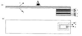
図1(a)は、本発明の被記録媒体の模式断面図である。ここで、2が基材であり、図に示されているように、基材1の一方の面にインク受容層1が設けられ、それとは反対側の面に、接着層3、インク遮蔽構造4、接着層3、無線情報素子5、接着層3、インク遮蔽構造4、接着層3、剥離紙6が設置されている。
図1(b)は、図1(a)をA方向から見た透視図である。7が無線情報素子(図1(a)の無線情報素子5に対応)であり、例えば、ループ状コイル等からなる送受信アンテナ8と、ICチップ9である。
Hereinafter, the present invention will be described in more detail with reference to preferred embodiments.
FIG. 1A is a schematic cross-sectional view of a recording medium of the present invention. Here, 2 is a base material, and as shown in the figure, the ink receiving layer 1 is provided on one surface of the base material 1, and the adhesive layer 3 and the ink shielding structure are provided on the opposite surface. 4, an adhesive layer 3, a wireless information element 5, an adhesive layer 3, an ink shielding structure 4, an adhesive layer 3, and a release paper 6 are provided.
FIG. 1B is a perspective view of FIG. 1A viewed from the A direction. Reference numeral 7 denotes a wireless information element (corresponding to the wireless information element 5 in FIG. 1A), for example, a transmission / reception antenna 8 formed of a loop coil or the like, and an IC chip 9.
本発明の被記録媒体では、無線通信素子が、該バゲージタグを荷物に添付し識別票として使用するために、図示のように識別票の貼り合わせる位置に設置されている。もちろん図示のように、ループ状でも良いし、折り曲げ重ねて貼り合わせても良い。また本発明では、識別票をお互いに貼り合わせるようにしたが、貼り合わせるための別の媒体が用意されても、本発明の範囲に入る。 In the recording medium of the present invention, the wireless communication element is installed at a position where the identification tag is pasted as shown in the figure in order to attach the baggage tag to a package and use it as an identification tag. Of course, as shown in the figure, it may be in the form of a loop, or may be folded and bonded together. Further, in the present invention, the identification tags are pasted together, but even if another medium for pasting is prepared, it falls within the scope of the present invention.
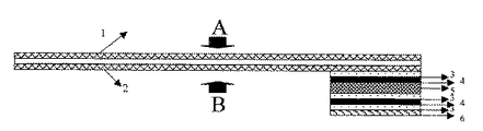
図2は、本発明の被記録媒体の画像形成方法及び、発明のバゲージタグを荷物に添付し識別票として使用する方法を説明する模式図である。図1(a)と同じものには同じ付番をしている。
図2(a)はAの方向から、インク滴10で画像11を形成後、剥離紙6を剥がし、荷物の取っ手等に通して、貼り合わせて識別票として使用する。
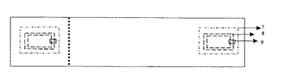
図2(b)は、本発明の被記録媒体に画像形成後、A方向から見た模式平面図である。図に示すように、無線通信素子部の設置位置に関わらず、本発明の被記録媒体の全面に、搭乗する旅客機の便名、搭乗者名、バゲージタグの発行日付、バーコード更には、広告等が視認情報として記録される。又特開2003−306228号のバゲージタグ発行システムを使用すれば、搭乗者情報にあわせた広告等の視認情報や搭乗者名の顔写真等も記録可能となる。
FIG. 2 is a schematic diagram for explaining an image forming method of a recording medium of the present invention and a method of using the baggage tag of the present invention as an identification tag attached to a package. The same numbers are assigned to the same components as those in FIG.
In FIG. 2A, the image 11 is formed with the ink droplets 10 from the direction A, and then the release paper 6 is peeled off, passed through a luggage handle or the like, and bonded to be used as an identification tag.
FIG. 2B is a schematic plan view seen from the A direction after image formation on the recording medium of the present invention. As shown in the figure, regardless of the installation position of the wireless communication element unit, the flight name of the passenger aircraft, the name of the passenger, the issue date of the baggage tag, the barcode, the advertisement, etc. on the entire surface of the recording medium of the present invention Is recorded as visual information. Further, if the baggage tag issuing system disclosed in Japanese Patent Application Laid-Open No. 2003-306228 is used, it is possible to record visual information such as advertisements according to the passenger information, a facial photograph of the passenger name, and the like.
又当然ながら、無線通信素子部には、電子情報として、上記した通常の視認情報の他に、搭乗者の性別、搭乗者の年齢、バゲッジタグの発効日時、荷物のセキュリティチェック情報、搭乗者が旅客機に搭乗したことを記録する搭乗確認情報、データベースの記録情報を参照する際に使用するIDナンバー、電子透かし等の改ざん防止処理等が記憶(記録)されている。 Of course, in addition to the above-mentioned normal visual information, the wireless communication element section has the passenger's gender, passenger age, baggage tag effective date, baggage security check information, passenger The boarding confirmation information for recording the boarding, the ID number used when referring to the recorded information in the database, the falsification preventing process such as digital watermark, etc. are stored (recorded).
図2(C)は、本発明の被記録媒体を荷物に添付し識別票として使用する場合の模式図である。本発明の被記録媒体の貼合わせ部に、図示のごとく被記録媒体の端部を重ね、無線通信素子部が被記録媒体の重ねの位置にある為に、無線通信素子部が剥き出しにならない構造になる為に、荷物輸送時の外部の影響(水、湿度、温度)から保護され、且つ無線通信素子部が識別票として使用する際に比較的に平坦部に位置するために、荷物輸送時にかかるストレスからも保護される。又外部からは、該素子部が設置されている事が視認しにくい為に、荷物輸送時のセキュリティー性が向上される。またセキュリティー性を向上させる為に、画像物の上に改ざん防止層を別途設けても良い。 FIG. 2C is a schematic diagram when the recording medium of the present invention is attached to a package and used as an identification tag. A structure in which the end of the recording medium is overlapped with the pasting portion of the recording medium of the present invention as shown in the figure, and the wireless communication element portion is not exposed because the wireless communication element portion is at the overlapping position of the recording medium. Because it is protected from external influences (water, humidity, temperature) at the time of cargo transportation, and the wireless communication element part is located on a relatively flat part when used as an identification tag, It is protected from such stress. In addition, since it is difficult to visually recognize that the element portion is installed from the outside, the security during transportation of the luggage is improved. In order to improve security, a tamper-proof layer may be separately provided on the image object.
図2(d)は、図2(c)に示す被記録媒体と異なり、本発明の被記録媒体を荷物に添付し識別票として使用する場合の別の形態による模式図である。貼り合わせ位置は図示の如く被記録媒体の両端部で貼り合わせずに、使用用途に合わせて適宜に貼り合わせ位置を変更した例を示す。なお、この例でも、同じ被記録媒体に貼り合わせる例を示したが、他の媒体に張り合わせても良い。
続いて本発明で使用するに構成材料について説明する。
FIG. 2D is a schematic diagram according to another embodiment when the recording medium of the present invention is attached to a package and used as an identification card, unlike the recording medium shown in FIG. As shown in the figure, the bonding position is not bonded at both ends of the recording medium, and the bonding position is appropriately changed according to the intended use. In this example as well, an example of pasting on the same recording medium is shown, but it may be pasted on another medium.
Subsequently, constituent materials used in the present invention will be described.
(無線通信素子)
本発明の無線通信素子7とは、非接触で情報の書き込み又は読み書き可能にするのに必要なCPU、メモリ等、電気的に連結された素子を有していれば、特に限定される物ではなく、プラスチック等の基材上のコイルパターンと容量素子により共振回路を形成して一定周波数の電波を受信して交信することができる。一般的には125kHz、13.56MHz、2.45GHz(マイクロ波)の周波数帯が使用される。マイクロ波の場合の交信距離は数mといわれる。その大きさも30mm×30mm程度以下のサイズにできるが、ICバゲージタグの場合はかなり大きな面積があるので設計を比較的自由に行うことができる。また送受信アンテナ8は、細線の捲線により形成しても、コアシートにプリント配線技術またフォトエッチングにより形成しても良い。また、ディアクティベーター機能付きの無線通信素子を使用しても良い。
(Wireless communication element)
The wireless communication element 7 of the present invention is not particularly limited as long as it has electrically connected elements such as a CPU and a memory necessary to enable writing or reading of information without contact. In addition, a resonance circuit can be formed by a coil pattern on a base material such as plastic and a capacitive element, and radio waves of a constant frequency can be received and communicated. Generally, frequency bands of 125 kHz, 13.56 MHz, and 2.45 GHz (microwave) are used. The communication distance in the case of microwaves is said to be several meters. The size can be reduced to about 30 mm × 30 mm or less, but since an IC baggage tag has a considerably large area, the design can be performed relatively freely. Further, the transmission / reception antenna 8 may be formed of a fine wire or a core sheet may be formed by a printed wiring technique or photoetching. A wireless communication element with a deactivator function may be used.
(基材)
本発明のにおいて使用する基材は、図1に示すように、インク受容層、接着層3、インク遮蔽構造4、接着層3、無線情報素子5および剥離紙6の保持が可能であり、且つプリンタでの搬送が可能であれば、何れの基材も使用できる。
(Base material)
As shown in FIG. 1, the substrate used in the present invention can hold the ink receiving layer, the adhesive layer 3, the ink shielding structure 4, the adhesive layer 3, the wireless information element 5 and the release paper 6, and Any substrate can be used as long as it can be conveyed by a printer.
その中でも、インクジェット記録適性の観点及び、荷物輸送時の厳しい環境に耐えうる観点で、通気性微細孔を含んでなるフィルムまたはシート(以下、「多孔質フィルム」と総称する。)を使用する事が好ましい。基材が多孔質体であることにより、記録媒体に適用されるインク中の水等の溶媒(分散媒)をいち早く吸収し、速乾性を高めることができる。 Among these, from the viewpoint of ink jet recording suitability and the ability to withstand harsh environments during cargo transportation, a film or sheet (hereinafter collectively referred to as “porous film”) including air-permeable fine holes is used. Is preferred. When the substrate is a porous body, it is possible to quickly absorb a solvent (dispersion medium) such as water in the ink applied to the recording medium, and to improve the quick drying property.
多孔質フィルムは、上記のような効果を奏するものであれば特に限定されず、従来から画像記録媒体に使用されているものが使用できる。この多孔質フィルムの材料の具体例としては、ポリエチレン、ポリプロピレン、ポリメチルペンテン−1等のポリオレフィン、ポリ塩化ビニル、ポリスチレン、スチレンーブタジエンーアクリルニトリル共重合体、ポリアミド、ポリメチルメタアクリレート、ポリエステルなどが挙げられ、これらは2種以上混合して用いることができる。また、市販品としては、PPG インダストリー(株)社の多孔性延伸樹脂フィルム、(商標)Teslin樹脂フィルム等が好適である。
この基材は通気性微細孔を含むため通気性であるが、その通気性は、ガレー透気度を用いて規定すれば、通常10〜3,000秒/100mL、好適には50〜2,500秒/100mL、特に好適には100〜2,000秒/100mLの範囲である。
The porous film is not particularly limited as long as it has the above effects, and those conventionally used for image recording media can be used. Specific examples of the material for the porous film include polyolefins such as polyethylene, polypropylene, and polymethylpentene-1, polyvinyl chloride, polystyrene, styrene-butadiene-acrylonitrile copolymer, polyamide, polymethyl methacrylate, polyester, and the like. These can be used as a mixture of two or more. Moreover, as a commercial item, the porous stretched resin film of the PPG Industry Co., Ltd., (trademark) Teslin resin film, etc. are suitable.
This base material is air permeable because it contains air permeable micropores, but the air permeability is usually 10 to 3,000 seconds / 100 mL, preferably 50 to 2, if defined using galley air permeability. The range is 500 seconds / 100 mL, particularly preferably 100 to 2,000 seconds / 100 mL.
なお、ここでいうガレー透気度は、JISP−8117−1980に準拠し、ガレー透気度試験機を用いて測定した値であり、通常100mLの体積の空気が通過するのに要する時間で表わされる。多孔質フィルムの空隙率(フィルム全体の体積に占める空隙の体積)は、通常10〜90体積%、好適には20〜80体積%である。また、フィルムの肉厚断面方向に垂直(延伸フィルムの水平方向)に切断して測定される孔の径は、通常0.01〜3μm、好適には0.02〜2μm、特に好適には0.03〜1μmである。
基材全体の厚さは、30〜500μm、好ましくは50〜300μmである。厚みが薄すぎると、インク乾燥性が低下するおそれと、荷物輸送時に破損する恐れがあり、反対に厚すぎると、プリンタ搬送時の記録媒体の取り扱いに不便が生じるおそれがある。
The galley air permeability referred to here is a value measured using a galley air permeability tester in accordance with JISP-8117-1980, and is usually represented by the time required for 100 mL of air to pass through. It is. The porosity of the porous film (the volume of the voids in the entire film volume) is usually 10 to 90% by volume, preferably 20 to 80% by volume. Moreover, the diameter of the hole measured by cutting perpendicularly to the thickness cross-sectional direction of the film (horizontal direction of the stretched film) is usually 0.01 to 3 μm, preferably 0.02 to 2 μm, particularly preferably 0. 0.03 to 1 μm.
The thickness of the whole base material is 30-500 micrometers, Preferably it is 50-300 micrometers. If the thickness is too thin, there is a risk that the ink drying property may be reduced and the bag may be damaged during transportation. On the other hand, if the thickness is too thick, handling of the recording medium may be inconvenient when the printer is transported.
一方、前記基材の表面および前記微細孔は、界面活性剤により親水化処理されていることが好ましい。印刷したインク画像の速乾性を効果的に高めるからである。界面活性剤としては、アニオン性、カチオン性、両性およびノニオン性のいずれのものも使用できる。アニオン性のものとしては、例えば、カルボン酸塩系、スルホン酸塩系、燐酸エステル塩系等が使用でき、カチオン性のものとしては、例えば、アミン塩系、四級アンモニウム塩系等が使用でき、両性のものとしては、例えば、ベタイン系、スルホベタイン系等が使用でき、ノニオン性のものとしては、例えば、ポリエチレングリコール等のポリオキシアルキレン系、ソルビタン系、ソリビトール系等が使用できる。 On the other hand, it is preferable that the surface of the base material and the micropores are subjected to a hydrophilic treatment with a surfactant. This is because the quick drying property of the printed ink image is effectively enhanced. As the surfactant, any of anionic, cationic, amphoteric and nonionic can be used. Examples of anionic compounds include carboxylate salts, sulfonate salts, and phosphate ester salts. Examples of cationic substances include amine salts and quaternary ammonium salts. As amphoteric ones, for example, betaine type, sulfobetaine type and the like can be used, and as nonionic ones, for example, polyoxyalkylene type such as polyethylene glycol, sorbitan type, sorbitol type and the like can be used.
親水化処理は、インク受容層を形成するための塗布液に界面活性剤を添加し、その塗布液を基材表面に塗布し、インク受容層の形成と同時に行うことができる。また、受容層形成前に行うこともできる。すなわち、まず、基材の表面に界面活性剤を含む液体を塗布し、または基材をその液体に含浸し、親水化処理を行った後、親水化処理された基材の表面に、ポリマーと凝集剤とを含む液体を塗布する等により、インク受容層を形成することが好ましい。この方法は、速乾性の高い画像記録媒体を特に容易に製造することができる。
前述の様に、親水化処理を、界面活性剤を含む液体を塗布、乾燥して行う場合、溶媒として、水や、エタノール等のアルコールを用いるのが好適である。界面活性剤を含む液体中の界面活性剤濃度は、通常1〜30質量%、好適には5〜25質量%である。また、塗布装置には、通常のコータ、たとえば、バーコータ、ナイフコータ、ロールコータ、ダイコータ等を使用することできる。
The hydrophilization treatment can be performed simultaneously with the formation of the ink receiving layer by adding a surfactant to the coating liquid for forming the ink receiving layer and applying the coating liquid to the surface of the substrate. Moreover, it can also carry out before formation of a receiving layer. That is, first, a liquid containing a surfactant is applied to the surface of the base material, or the base material is impregnated with the liquid and subjected to a hydrophilic treatment, and then the polymer and The ink receiving layer is preferably formed by applying a liquid containing a flocculant. This method can particularly easily produce an image recording medium having a high quick-drying property.
As described above, when the hydrophilization treatment is performed by applying and drying a liquid containing a surfactant, it is preferable to use water or an alcohol such as ethanol as a solvent. The surfactant concentration in the liquid containing the surfactant is usually 1 to 30% by mass, preferably 5 to 25% by mass. Moreover, a normal coater, for example, a bar coater, a knife coater, a roll coater, a die coater, or the like can be used for the coating apparatus.
多孔質フィルムには、必要に応じて無機微細粉末を含有させる。無機微細粉末としては、炭酸カルシウム、アルミナ、焼成クレイ、シリカ(アモルファスシリカを含む)、珪藻土、タルク、酸化チタン、硫酸バリウム等を使用することができる。微細粉末の粒径は、通常0.3〜10μm、好適には0.8〜5μmである。また、その他の添加剤、たとえば、熱安定剤、紫外線吸収剤、分散剤、帯電防止剤、酸化防止剤、オイル(鉱油等)などを配合することもできる。
上記した基材を使用すれば、特に受容層を設けなくても、高画質の視認情報を要求しなければ、画像形成が可能となる。例えば、図1(a)のB方向からでも、接着層3インク遮蔽構造4接着層3無線情報素子5剥離紙6が積層されていない領域には、本発明の被記録媒体の使用方法などをインクジェット画像として記録可能である。
The porous film contains an inorganic fine powder as necessary. As the inorganic fine powder, calcium carbonate, alumina, calcined clay, silica (including amorphous silica), diatomaceous earth, talc, titanium oxide, barium sulfate and the like can be used. The particle size of the fine powder is usually 0.3 to 10 μm, preferably 0.8 to 5 μm. In addition, other additives such as a heat stabilizer, an ultraviolet absorber, a dispersant, an antistatic agent, an antioxidant, an oil (mineral oil, etc.) can be blended.
If the above-described base material is used, an image can be formed without requiring a high-quality visual information without providing a receiving layer. For example, even from the direction B in FIG. 1A, the area where the adhesive layer 3 ink shielding structure 4 adhesive layer 3 wireless information element 5 release paper 6 is not laminated is provided with a method for using the recording medium of the present invention. It can be recorded as an inkjet image.
(インク受容層)
本発明による被記録媒体のインク受容層の形成材料としては、従来公知の材料が適宜に使用できるが、中でも、有機ポリマーと、水溶性の有機酸または無機酸の塩を含んでなる凝集剤、とを含有することが好ましい。このような凝集剤は、媒体表面に水性インクが適用(印刷等)された時、顔料等の着色成分をすばやくインク受容層の表面で凝集させる。したがって、顔料等が、媒体内部の孔内まで移行することを効果的に防止し、速乾性を高めることができる。また、凝集剤に加えて有機ポリマーを含有することは、上記のような凝集作用と、ポリマーの結着作用との相乗効果により、表面に定着されたインク像の耐水性を、効果的に高めることができる。又、インク受容層は単層であってもよいし、高い性能を付加する目的で多層構造にしてもよい。
(Ink receiving layer)
As a material for forming the ink receiving layer of the recording medium according to the present invention, conventionally known materials can be used as appropriate. Among them, a flocculant comprising an organic polymer and a salt of a water-soluble organic acid or inorganic acid, It is preferable to contain. Such an aggregating agent quickly aggregates coloring components such as pigments on the surface of the ink receiving layer when aqueous ink is applied (printed or the like) to the medium surface. Therefore, it is possible to effectively prevent the pigment and the like from moving into the pores inside the medium and improve the quick drying property. Further, the inclusion of the organic polymer in addition to the aggregating agent effectively increases the water resistance of the ink image fixed on the surface due to the synergistic effect of the aggregating action as described above and the binding action of the polymer. be able to. Further, the ink receiving layer may be a single layer or may have a multilayer structure for the purpose of adding high performance.
受容層のポリマーが、分子内に極性官能基を有する極性ポリマーの場合、凝集剤と極性ポリマーとの相乗効果により、水性インク凝集作用が効果的に高められる。このような極性ポリマーとしては、カチオン変性ポリウレタンや、ポリビニルピロリドン等の塩基性ポリマーが好適である。
有機ポリマーとしては、前述のカチオン変性ポリウレタン等の他、ポリオレフィン、ポリ塩化ビニル、ポリ塩化ビニリデン、ポリスチレン、スチレン・ブタジエン・アクリロニトリル共重合体、ポリアミド、アクリル系ポリマー、ポリエステル、通常の(変性していない)ポリウレタン等も使用することができる。
When the polymer of the receiving layer is a polar polymer having a polar functional group in the molecule, the water-based ink aggregation action is effectively enhanced by the synergistic effect of the aggregating agent and the polar polymer. As such a polar polymer, a basic polymer such as cation-modified polyurethane or polyvinylpyrrolidone is suitable.
Organic polymers include polyolefins, polyvinyl chloride, polyvinylidene chloride, polystyrene, styrene / butadiene / acrylonitrile copolymers, polyamides, acrylic polymers, polyesters, ordinary (unmodified) ) Polyurethane and the like can also be used.
有機酸又は無機酸の塩としては、多価金属塩が好適である。凝集作用が比較的高く、速乾性と、定着インク像の耐水性とを同時に高める効果にすぐれるからである。多価金属イオンとしては、アルミニウム、ガリウム、チタン、ジルコニウム、ハフニウム、亜鉛、マグネシウム、カルシウム、ニオブ、タンタル、鉄、銅、スズ、コバルト等のうちの、1または2以上を組み合わせて使用することができる。 As the salt of the organic acid or inorganic acid, a polyvalent metal salt is suitable. This is because the aggregating action is relatively high, and it is excellent in the effect of simultaneously improving quick drying and water resistance of the fixed ink image. As the polyvalent metal ion, one or more of aluminum, gallium, titanium, zirconium, hafnium, zinc, magnesium, calcium, niobium, tantalum, iron, copper, tin, cobalt, etc. may be used in combination. it can.
無機酸の例として好適には、硫酸、硝酸、または塩酸である。有機ポリマーが、カチオン変性ポリウレタン等のカチオン変性ポリマーの場合、有機酸塩よりも無機酸塩が好適である。速乾性と耐水性とを効果的に高めることができるからである。無機酸塩として好適には、硫酸アルミニウムである。その理由の詳細については明らかではないが、ポリマーのカチオン部分と、硫酸イオンおよびアルミニウムイオンとの相互作用により、インク定着力を効果的に高めるためと考えられる。 Preferred examples of the inorganic acid are sulfuric acid, nitric acid, and hydrochloric acid. In the case where the organic polymer is a cation-modified polymer such as cation-modified polyurethane, an inorganic acid salt is preferable to an organic acid salt. This is because quick drying and water resistance can be effectively enhanced. A preferred inorganic salt is aluminum sulfate. Although the details of the reason are not clear, it is considered that the ink fixing force is effectively increased by the interaction between the cation portion of the polymer and sulfate ions and aluminum ions.
有機酸の例として好適には、芳香族の、カルボン酸、スルホン酸、スルホカルボン酸、ヒドロキシスルホカルボン酸、またはヒドロキシカルボン酸を使用することができる。これらの酸のうち、1または2以上を組み合わせて使用することができる。
インク受容層に含まれる凝集剤の量は、有機ポリマー100質量部に対して、通常1〜70質量部、好適には3〜50質量部、特に好適には5〜30質量部である。凝集剤の量が少なすぎるとインク定着力が低下し、耐水性や発色性が低下するおそれがあり、反対に多すぎるとインク像のにじみが生じるおそれがある。
As an example of the organic acid, an aromatic carboxylic acid, sulfonic acid, sulfocarboxylic acid, hydroxysulfocarboxylic acid, or hydroxycarboxylic acid can be preferably used. Among these acids, one or two or more can be used in combination.
The amount of the aggregating agent contained in the ink receiving layer is usually 1 to 70 parts by mass, preferably 3 to 50 parts by mass, particularly preferably 5 to 30 parts by mass with respect to 100 parts by mass of the organic polymer. If the amount of the aggregating agent is too small, the ink fixing ability may be reduced, and the water resistance and color developability may be lowered. On the other hand, if the amount is too large, the ink image may be blurred.
インク受容層には、受容層の多孔性を高めるために、必要に応じて無機微細粉末を含ませることもできる。無機微細粉末としては、炭酸カルシウム、アルミナ、焼成クレイ、シリカ(アモルファスシリカを含む)、珪藻土、タルク、酸化チタン、硫酸バリウム等が使用できる。微細粉末の粒径は、通常0.3〜10μm、好適には0.8〜5μmである。また、その他の添加剤、たとえば、熱安定剤、紫外線吸収剤、分散剤、帯電防止剤、酸化防止剤、などを配合することもできる。
インク受容層の厚さは、本発明の効果を損なわない限り特に限定されない。厚みが薄すぎると、インク乾燥性が低下するおそれと、荷物輸送時に破損する恐れがあり、反対に厚すぎると、プリンタ搬送時の記録媒体の取り扱いに不便が生じるおそれがある。この様な観点から、受容層の厚さは、通常5〜200μm、好適には10〜100μmである。
インク受容層は、例えば、凝集剤および有機ポリマーを含む液体を塗布、乾燥することにより形成する。その場合の溶媒として、水やアルコールを用いることが好適である。また、塗布装置には、通常のコータ、たとえば、バーコータ、ナイフコータ、ロールコータ、ダイコータ等を使用することができる。
In order to increase the porosity of the receiving layer, the ink receiving layer may contain an inorganic fine powder as necessary. As the inorganic fine powder, calcium carbonate, alumina, calcined clay, silica (including amorphous silica), diatomaceous earth, talc, titanium oxide, barium sulfate and the like can be used. The particle size of the fine powder is usually 0.3 to 10 μm, preferably 0.8 to 5 μm. In addition, other additives such as a heat stabilizer, an ultraviolet absorber, a dispersant, an antistatic agent, an antioxidant, and the like can be blended.
The thickness of the ink receiving layer is not particularly limited as long as the effects of the present invention are not impaired. If the thickness is too thin, there is a risk that the ink drying property may be reduced and the bag may be damaged during transportation. On the other hand, if the thickness is too thick, handling of the recording medium may be inconvenient when the printer is transported. From such a viewpoint, the thickness of the receiving layer is usually 5 to 200 μm, preferably 10 to 100 μm.
The ink receiving layer is formed, for example, by applying and drying a liquid containing an aggregating agent and an organic polymer. In this case, it is preferable to use water or alcohol as the solvent. Moreover, a normal coater, for example, a bar coater, a knife coater, a roll coater, a die coater, or the like can be used for the coating apparatus.
インクジェット記録適性、例えば、耐ビーディング性や耐ブロッキング性等を向上させる目的で、更に、得られるインクジェット記録物の保存性、例えば、高湿環境下における画像の滲みや耐水性等を向上する目的で、インク受容層中には、上記材料の他に、水溶性の低分子有機化合物、及びカチオン性化合物、更には水不溶性の有機化合物を適宜に使用することができる。 For the purpose of improving ink jet recording suitability, for example, beading resistance and blocking resistance, and for the purpose of further improving the storage stability of the obtained ink jet recorded material, for example, image bleeding and water resistance in a high humidity environment. In the ink receiving layer, in addition to the above materials, a water-soluble low-molecular organic compound, a cationic compound, and further a water-insoluble organic compound can be appropriately used.
図3に本発明の別の形態のバゲージタグを示す。これは、基材の両面にインク受容層を設けている為に、B方向からでも高画質なインクジェット画像形成が可能となる。 FIG. 3 shows a baggage tag according to another embodiment of the present invention. This is because the ink-receiving layer is provided on both surfaces of the base material, so that high-quality inkjet image formation is possible even from the B direction.
(インク遮蔽構造)
本発明で用いるインク遮蔽構造の具体的な構成としては、本発明の被記録媒体を識別票として使用する際に、画像部に付与されたインク成分が、無線通信素子にまで及ばない構造とすることが挙げられる。実施の形態としては、基材と無線通信素子の間にインク遮蔽層を設けた構造とすることで、記録によって付与されたインク成分が画像部から拡散/浸透して無線通信素子4にまで及ぶことのないように構成する。
(Ink shielding structure)
As a specific configuration of the ink shielding structure used in the present invention, when the recording medium of the present invention is used as an identification tag, the ink component applied to the image portion does not reach the wireless communication element. Can be mentioned. As an embodiment, by adopting a structure in which an ink shielding layer is provided between the base material and the wireless communication element, the ink component applied by recording diffuses / penetrates from the image portion and reaches the wireless communication element 4. It is configured so that there is nothing.
従って、インク遮蔽層は、画像部と無線通信素子の間にあれば特に限定されず、任意の位置に設ける事ができる。例えば、インク遮蔽層をもう一方の貼り合わせ部に設けることも出来る。図4がその模式図である。 Therefore, the ink shielding layer is not particularly limited as long as it is between the image portion and the wireless communication element, and can be provided at an arbitrary position. For example, an ink shielding layer can be provided on the other bonding portion. FIG. 4 is a schematic diagram thereof.
本発明で使用するインク遮蔽層の形成材料として、例えば、従来公知のカップリング剤(シラン系、チタン系)、界面活性剤、及び樹脂(エマルジョンを含む)等が挙げられる。 Examples of the material for forming the ink shielding layer used in the present invention include conventionally known coupling agents (silane-based and titanium-based), surfactants, resins (including emulsions), and the like.
特に、均一で強靭な連続皮膜を形成することが容易な点で樹脂が好ましく用いられる。 In particular, a resin is preferably used because it is easy to form a uniform and tough continuous film.
この様なものとしては、例えば、ポリエチレン、ポリプロピレン、ポリスチレン、ポリイソプレン、セルロース、酢酸セルロース、ポリ酢酸ビニル、ポリビニルアセタール、ポリメタクリル酸エステル、ポリエステル、ポリカーボネート、エポキシ樹脂、フェノール樹脂、アルキド樹脂、ポリアクリロニトリル、ポリアミド、尿素樹脂、メラミン樹脂、ウレタン樹脂、ポリ塩化ビニル、ポリ塩化ビニリデン、クロロプレン、ポリフルオロエチレン、ポリ三フッ化塩化エチレン、シリコーン樹脂等が挙げられるが、耐水性、耐アルカリ性、耐酸性に優れているものを選択するのが好ましい。また、使用する樹脂は高純度であり、アルカリ金属イオンや塩素イオン不純物を取り除くことが好ましい。厚みとしては、0.1〜100[μm]が好ましい。インク遮蔽層の厚みが極端に薄い場合は、荷物物流の際の厳しい環境において破損する恐れが有り、厚すぎるとプリンタ搬送時の記録媒体の取り扱いに不便が生じるおそれがある。 Examples of such materials include polyethylene, polypropylene, polystyrene, polyisoprene, cellulose, cellulose acetate, polyvinyl acetate, polyvinyl acetal, polymethacrylate, polyester, polycarbonate, epoxy resin, phenol resin, alkyd resin, and polyacrylonitrile. , Polyamide, urea resin, melamine resin, urethane resin, polyvinyl chloride, polyvinylidene chloride, chloroprene, polyfluoroethylene, polytrifluoroethylene chloride, silicone resin, etc., but water resistance, alkali resistance, acid resistance It is preferable to select one that is superior. In addition, the resin used is highly pure, and it is preferable to remove alkali metal ions and chlorine ion impurities. The thickness is preferably 0.1 to 100 [μm]. If the thickness of the ink shielding layer is extremely thin, the ink shielding layer may be damaged in a harsh environment during cargo distribution, and if it is too thick, there is a risk of inconvenience in handling the recording medium when the printer is transported.
しかし、本発明はこれらの方法に限定されるものではなく、インク遮蔽層として、例えば、上記した材料でインク受容層の基材として用いる方法や,既に表面に離型処理されている基材を用いる方法や、撥水材料からなる基材を使用してインク遮蔽層を形成する方法等であってもよい。
(接着層)
接着層は、本発明の被記録媒体を荷物の取って等に通して、貼り合わせて使用する。また基材とインク遮蔽層、インク遮蔽層と無線情報素子を接着させる為に使用する。従って、粘着層に含有される粘着剤としては、特に限定される物では無いく、常温で粘着性を示し、感圧接着剤として使用可能なポリマーが好適に使用できる。例えば、ゴム系、アクリル系、シリコーン系、ポリエステル系、ビニルエーテル系等溶剤型・無溶剤型の各種の公知の粘着剤を使用することができる。ゴム系粘着剤としては天然ゴムやスチレン−ブタジエンゴム等を主原料とし、ロジン系樹脂や各種の可塑剤が含有される。
又必要に応じて熱硬化性樹脂やホットメルト接着剤や平4−19568で開示されている遅延接着剤や自着性感圧接着剤層を使用することもできる。
However, the present invention is not limited to these methods, and as an ink shielding layer, for example, a method of using the above-mentioned material as a base material of an ink receiving layer or a base material that has already been subjected to a release treatment on the surface. The method of using, the method of forming an ink shielding layer using the base material which consists of a water repellent material, etc. may be sufficient.
(Adhesive layer)
The adhesive layer is used after the recording medium of the present invention is passed through a package or the like and bonded together. Further, it is used for bonding the base material and the ink shielding layer, and the ink shielding layer and the wireless information element. Therefore, the pressure-sensitive adhesive contained in the pressure-sensitive adhesive layer is not particularly limited, and a polymer that exhibits pressure-sensitive adhesive properties at room temperature and can be used as a pressure-sensitive adhesive can be suitably used. For example, various known pressure-sensitive adhesives such as rubber-based, acrylic-based, silicone-based, polyester-based, and vinyl ether-based solvent types and solventless types can be used. As the rubber-based adhesive, natural rubber, styrene-butadiene rubber or the like is mainly used, and rosin-based resin and various plasticizers are contained.
Further, if necessary, a thermosetting resin, a hot melt adhesive, a delayed adhesive or a self-adhesive pressure-sensitive adhesive layer disclosed in Japanese Patent Laid-Open No. 4-19568 can be used.
(剥離紙)
本発明の剥離紙は、接着層を保護する目的で設置し、紙やフィルム等の従来公知の基材上に離型層を設けられていれば、特に限定される物ではない。
また、剥離紙は本発明の記録媒体に画像形成後、剥がして接着層を基材の裏面に貼り合わせて使用する。よって、取り扱い向上の為に、プリンタ搬送時の記録媒体の取り扱いに不便が起こらない範囲で、接着層より大きな面積を所有しても良い。
離型層に用いられる材料としては、先ず、熱溶融性材料としては、カルナウバワックス、パラフィンワックス、マイクロクリスタリンワックス、カスターワックス等のワックス類、ステアリン酸、パルミチン酸、ラウリン酸、ステアリン酸アルミニウム、ステアリン酸鉛、ステアリン酸バリウム、ステアリン酸亜鉛、パルミチン酸亜鉛、メチルヒドロキシステアレート、グリセロールモノヒドロキシステアレート、グリセロールモノヒドロキシステアレート等の高級脂肪酸、或いはその金属塩、エステル等の誘導体、ポリアミド系樹脂、石油系樹脂、ロジン誘導体、クロマン−インデン樹脂、テルペン系樹脂、ノボラック系樹脂、スチレン系樹脂、ポリエチレン、ポリプロピレン、ポリブテン、酸化ポリオレフィン等のオレフィン系樹脂、ビニルエーテル系樹脂等が挙げられる。又、この他に、シリコーン樹脂、フルオロシリコーン樹脂、フルオロオレフィンビニルエーテルターポリマー、パーフルオロエポキシ樹脂、パーフルオロアルキル基を側鎖に持つ熱硬化型アクリル樹脂やフッ化ビニリデン系硬化型塗料等も用いることができる。
(Release paper)
The release paper of the present invention is not particularly limited as long as it is installed for the purpose of protecting the adhesive layer and a release layer is provided on a conventionally known substrate such as paper or film.
Further, the release paper is peeled off after forming an image on the recording medium of the present invention, and the adhesive layer is attached to the back surface of the substrate. Therefore, in order to improve handling, an area larger than the adhesive layer may be owned as long as there is no inconvenience in handling of the recording medium when the printer is transported.
As a material used for the release layer, first, as a heat-meltable material, waxes such as carnauba wax, paraffin wax, microcrystalline wax, caster wax, stearic acid, palmitic acid, lauric acid, aluminum stearate, Higher fatty acids such as lead stearate, barium stearate, zinc stearate, zinc palmitate, methylhydroxystearate, glycerol monohydroxystearate, glycerol monohydroxystearate, metal salts, derivatives such as esters, polyamide resins , Petroleum resins, rosin derivatives, chroman-indene resins, terpene resins, novolac resins, styrene resins, olefin resins such as polyethylene, polypropylene, polybutene, and polyolefin oxide, Ether-based resin and the like. In addition, silicone resins, fluorosilicone resins, fluoroolefin vinyl ether terpolymers, perfluoroepoxy resins, thermosetting acrylic resins having a perfluoroalkyl group in the side chain, vinylidene fluoride curable coating materials, etc. should be used. Can do.
次に本発明の別の形態について説明する。 Next, another embodiment of the present invention will be described.
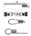
図5は、本発明の別の形態のバゲージタグである。バゲージタグに控え票が付いており、控え票にもICタグが設けられていてバゲージタグ本体部分と同一の内容がICチップに記録されている。これにより荷物自動受取の際の認識票とすることができ、搭乗券を持たない場合にも自動ピッキングが可能となる。また必要に応じて控え票を必要枚数付加しても良い。 FIG. 5 is a baggage tag according to another embodiment of the present invention. The baggage tag is provided with a copy slip, and the copy slip is provided with an IC tag, and the same content as the baggage tag main body is recorded on the IC chip. As a result, it can be used as an identification card for automatic receipt of luggage, and automatic picking is possible even when a boarding pass is not provided. Further, a necessary number of copy slips may be added as necessary.
(製品形態)
本発明の被記録媒体は図1に示すようにタグ形態に加工しても良いし、図6に示すように、連続紙形態として加工し、インクジェット記録後に切り離してバゲージタグとしても良いし、印刷工程に合わせて適宜に加工できる。
(Product form)
The recording medium of the present invention may be processed into a tag form as shown in FIG. 1, or processed as a continuous paper form as shown in FIG. 6, and separated after ink jet recording to form a baggage tag. It can be processed appropriately according to.
(記録方法)
以上説明した本発明の被記録媒体に記録を行う場合のインク自体は、公知のものが何ら問題なく使用可能である。また、インクとしては直接染料、酸性染料、塩基性染料、反応性染料、食用色素に代表される水溶性染料が使用可能であり、通常のインクジェットプリント用のものであれば特に制限なく使用することができる。
(Recording method)
As the ink itself when recording on the recording medium of the present invention described above, a known ink can be used without any problem. In addition, as the ink, water-soluble dyes represented by direct dyes, acid dyes, basic dyes, reactive dyes, and food dyes can be used. Can do.
これらの中でも、直接染料及び/または酸性染料を含有するインクを用いことが好ましい。また、最終画像物の耐候性を考慮すると水性の顔料インク、油性顔料インクを使用しても良い。 Among these, it is preferable to use an ink containing a direct dye and / or an acid dye. In consideration of the weather resistance of the final image, an aqueous pigment ink or an oil pigment ink may be used.
(インクジェット記録方法)
次に、インクジェット記録方式について説明する。
又画像記録方法としてインクジェット方式を使用すれば、非接触で画像形成可能な為に、無線通信素子部の設置位置に関わらず、本発明の被記録媒体の全面に画像を記録する事が出来る。
インクジェット記録方法は、インクの小滴を種々の駆動原理を利用して、ノズルから吐出して記録を行う、従来公知の何れの記録方式にも適用可能である。
(Inkjet recording method)
Next, the ink jet recording method will be described.
Further, if an ink jet method is used as an image recording method, an image can be formed in a non-contact manner, so that an image can be recorded on the entire surface of the recording medium of the present invention regardless of the installation position of the wireless communication element portion.
The ink jet recording method can be applied to any conventionally known recording method in which ink droplets are ejected from nozzles using various driving principles for recording.
その代表例として、特開昭54−59936号公報に記載されている方法で、熱エネルギーの作用を受けたインクが急激な体積変化を生じ、この状態変化による作用力によって、インクをノズルから吐出させるインクジェット方式を挙げることができる。 As a representative example, the method described in Japanese Patent Application Laid-Open No. 54-59936 causes a sudden volume change of the ink subjected to the action of thermal energy, and the ink is ejected from the nozzle by the action force due to this state change. An inkjet method can be given.
本発明の被記録媒体への記録に好適な記録装置を以下に説明する。 A recording apparatus suitable for recording on the recording medium of the present invention will be described below.
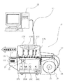
図6は、本実施例で使用する情報書き込み機能付き記録装置の概略構成図である。 FIG. 6 is a schematic configuration diagram of a recording apparatus with an information writing function used in this embodiment.
記録装置(12)は、被記録材に対して記録を行う、プリンタである。被記録材ユニット(19)に装着して搬送部に供給する。 The recording device (12) is a printer that performs recording on a recording material. It is mounted on the recording material unit (19) and supplied to the transport section.
搬送部は主に搬送モータ(20)と搬送ベルト(21)で構成され、記録時は図中の矢印方向に被記録材を搬送する機能を有する。 The transport unit is mainly composed of a transport motor (20) and a transport belt (21), and has a function of transporting a recording material in the direction of the arrow in the drawing during recording.
ここで、搬送経路上のロールユニット(19)側を搬送入口、逆側を搬送出口とする。記録装置は記録手段として、インクジェット記録ヘッドであるブラック(K)ヘッド(17K)、シアン(C)ヘッド(17C)、マジェンタ(M)ヘッド(17M)、イエロー(Y)ヘッド(17Y)を搭載し、これらはラベル幅分の長さのノズル列を持ったラインヘッドである。 Here, let the roll unit (19) side on a conveyance path be a conveyance inlet, and let a reverse side be a conveyance outlet. The recording apparatus is equipped with a black (K) head (17K), a cyan (C) head (17C), a magenta (M) head (17M), and a yellow (Y) head (17Y) as ink jet recording heads. These are line heads having a nozzle row having a length corresponding to the label width.
これら4本のヘッドからそれぞれK、C、M、Yのインクを選択的に吐出し、カラー記録する。 K, C, M, and Y inks are selectively ejected from these four heads, respectively, and color recording is performed.
吐出するインクは、ブラック(K)インクカートリッジ(18K)、シアン(18C)インクカートリッジ(18C)、マジェンタ(18M)インクカートリッジ(18M)、イエロー(18Y)インクカートリッジ(18Y)から、図示しないポンプによってそれぞれの記録ヘッドに供給される。 The ink to be ejected is from a black (K) ink cartridge (18K), cyan (18C) ink cartridge (18C), magenta (18M) ink cartridge (18M), yellow (18Y) ink cartridge (18Y) by a pump (not shown). Supplied to each recording head.
ロールユニット(19)は、非接触情報記録媒体(35)を装着するロール駆動軸(22)、被記録材のたるみにより位置が変化するロールセンサレバー(23)、ロール駆動軸(22)を駆動する図示しないロールモータから構成され、ロールセンサレバー(23)の状態によりロールモータを駆動、停止することで連続ラベル紙の給紙を行う。 The roll unit (19) drives the roll drive shaft (22) on which the non-contact information recording medium (35) is mounted, the roll sensor lever (23) whose position changes due to the slack of the recording material, and the roll drive shaft (22). The continuous label paper is fed by driving and stopping the roll motor according to the state of the roll sensor lever (23).
さらに、情報書き込み機能付き記録装置(11)と、ホストコンピュータ(25)はケーブル(13)で接続され、ホストコンピュータ(12)は記録データや記録媒体内蔵素子に書き込む情報等を制御コマンドとして記録装置(11)に転送する。 Furthermore, the recording device (11) with an information writing function and the host computer (25) are connected by a cable (13), and the host computer (12) uses the recording data and information to be written in the recording medium built-in element as a control command. Transfer to (11).
また、搬送出口付近には記録媒体内蔵素子に情報を書き込むための非接触通信部(14)が有り、通信アンテナ(15)及び無線通信素子との通信制御を行う非接触リーダ/ライタ(16)から構成されている。 In addition, there is a non-contact communication unit (14) for writing information to the recording medium built-in element in the vicinity of the conveyance exit, and a non-contact reader / writer (16) for controlling communication with the communication antenna (15) and the wireless communication element. It is composed of
このような装置を使用すれば、画像の記録と同時に記録媒体内蔵素子への情報の書き込みが可能となる。 If such an apparatus is used, it becomes possible to write information to the recording medium built-in element simultaneously with the recording of the image.
1 インク受容層
2 基材
3 接着層
4 インク遮蔽構造
5 無線情報素子
6 剥離紙
7 無線情報素子
8 送受信アンテナ
9 ICチップ
DESCRIPTION OF SYMBOLS 1
Claims (10)
An image forming method for forming an image by applying ink to a recording medium according to claim 1.
Priority Applications (2)
| Application Number | Priority Date | Filing Date | Title |
|---|---|---|---|
| JP2005371465A JP2007174460A (en) | 2005-12-26 | 2005-12-26 | Medium to be recorded, image object and image forming method |
| US11/613,391 US20070146464A1 (en) | 2005-12-26 | 2006-12-20 | Printing medium, image object, and image forming method |
Applications Claiming Priority (1)
| Application Number | Priority Date | Filing Date | Title |
|---|---|---|---|
| JP2005371465A JP2007174460A (en) | 2005-12-26 | 2005-12-26 | Medium to be recorded, image object and image forming method |
Publications (2)
| Publication Number | Publication Date |
|---|---|
| JP2007174460A true JP2007174460A (en) | 2007-07-05 |
| JP2007174460A5 JP2007174460A5 (en) | 2009-01-29 |
Family
ID=38193113
Family Applications (1)
| Application Number | Title | Priority Date | Filing Date |
|---|---|---|---|
| JP2005371465A Withdrawn JP2007174460A (en) | 2005-12-26 | 2005-12-26 | Medium to be recorded, image object and image forming method |
Country Status (2)
| Country | Link |
|---|---|
| US (1) | US20070146464A1 (en) |
| JP (1) | JP2007174460A (en) |
Cited By (1)
| Publication number | Priority date | Publication date | Assignee | Title |
|---|---|---|---|---|
| JP2009026173A (en) * | 2007-07-23 | 2009-02-05 | Dainippon Printing Co Ltd | Ic tag |
Families Citing this family (7)
| Publication number | Priority date | Publication date | Assignee | Title |
|---|---|---|---|---|
| US20100076865A1 (en) * | 2008-09-19 | 2010-03-25 | Pure Digital Technologies, Inc. | Method and system for personalizing portable electronic devices |
| US8352864B2 (en) | 2008-09-19 | 2013-01-08 | Cisco Technology, Inc. | Method of operating a design generator for personalization of electronic devices |
| US8296658B2 (en) * | 2008-09-19 | 2012-10-23 | Cisco Technology, Inc. | Generator for personalization of electronic devices |
| DE102010028342B4 (en) | 2010-04-29 | 2022-07-07 | Robert Bosch Gmbh | Parking system for a vehicle |
| EP2709042B1 (en) * | 2012-09-17 | 2016-11-02 | Sihl GmbH | Multilayer RFID loop tag comprising cold seal adhesive layers |
| JP2015003401A (en) * | 2013-06-19 | 2015-01-08 | セイコーエプソン株式会社 | Transportation device, printer and transportation method |
| EP3769262B1 (en) * | 2018-03-21 | 2023-10-18 | Avery Dennison Retail Information Services LLC | Ease of use supply matrix for identification of equipment |
Family Cites Families (8)
| Publication number | Priority date | Publication date | Assignee | Title |
|---|---|---|---|---|
| CA1127227A (en) * | 1977-10-03 | 1982-07-06 | Ichiro Endo | Liquid jet recording process and apparatus therefor |
| US6139672A (en) * | 1997-05-30 | 2000-10-31 | Canon Kabushiki Kaisha | Image-transfer medium for ink-jet recording and image-transfer printing process |
| US6406142B1 (en) * | 1997-07-26 | 2002-06-18 | Canon Kabushiki Kaisha | Image forming process using a transfer medium having a support with an index |
| US6652928B2 (en) * | 1998-01-28 | 2003-11-25 | Canon Kabushiki Kaisha | Image-transfer medium for ink-jet printing, production process of transferred image, and cloth with transferred image formed thereon |
| US20020048656A1 (en) * | 1998-01-28 | 2002-04-25 | Yuko Sato | Image-transfer medium for ink-jet printing, production process of transferred image, and cloth with transferred image formed thereon |
| US6871950B2 (en) * | 1998-02-13 | 2005-03-29 | Canon Kabushiki Kaisha | Image-transfer medium, production process of transferred image, and cloth with transferred image formed thereon |
| US6977112B2 (en) * | 2000-07-10 | 2005-12-20 | Canon Finetech, Inc. | Non-contact information recording medium for ink-jet recording and image forming process |
| US20050174371A1 (en) * | 2004-02-09 | 2005-08-11 | Deshmukh Sudhir G. | Process for monitoring dispensing of dispensable compositions |
-
2005
- 2005-12-26 JP JP2005371465A patent/JP2007174460A/en not_active Withdrawn
-
2006
- 2006-12-20 US US11/613,391 patent/US20070146464A1/en not_active Abandoned
Cited By (1)
| Publication number | Priority date | Publication date | Assignee | Title |
|---|---|---|---|---|
| JP2009026173A (en) * | 2007-07-23 | 2009-02-05 | Dainippon Printing Co Ltd | Ic tag |
Also Published As
| Publication number | Publication date |
|---|---|
| US20070146464A1 (en) | 2007-06-28 |
Similar Documents
| Publication | Publication Date | Title |
|---|---|---|
| JP2007174460A (en) | Medium to be recorded, image object and image forming method | |
| JP4289152B2 (en) | Baggage tag and how to use baggage tag | |
| JP4008546B2 (en) | Wireless information storage medium | |
| US8207824B2 (en) | Two sided thermal RFID | |
| JP2002319812A (en) | Data carrier adhesion method | |
| JP2003085520A (en) | Manufacturing method for ic card | |
| KR101215235B1 (en) | / ic tag reader/writer for the ic tag and system using the ic tag | |
| ATE229675T1 (en) | SECURITY LABEL/SAFETY TAGS WITH AN INTEGRATED RFID TRANSPONDER | |
| JP2007156668A (en) | Non-contact ic tag label and non-contact ic tag sheet | |
| JP2008176240A (en) | Both side display rfid sheet, and method for manufacturing the same | |
| JP2003168090A (en) | Compound tag, compound tag label, compound tag transfer sheet, article with compound tag, and element for compound tag | |
| US20140079894A1 (en) | Multilayer article having cold seal coatings | |
| WO2022076793A1 (en) | Thermal transfer ribbons and direct thermal print media including environmental exposure indicator material | |
| JP2007122466A (en) | Rfid tag | |
| EP3233509B1 (en) | Thermal sensitive media with internal rf printing matrix | |
| US20100013211A1 (en) | Identification tag | |
| EP1172761B1 (en) | Non-contact information recording medium for ink-jet recording | |
| JP2002072884A (en) | Continuous body of data memory element holding label | |
| JP3716087B2 (en) | IC card issuing system and IC card issuing method | |
| CN202502516U (en) | Anti-counterfeiting electronic label | |
| JP2003030619A (en) | Ic chip mounting body | |
| JP2002351336A (en) | Aviation luggage tag | |
| JP4627583B2 (en) | Laminated label | |
| CN215769781U (en) | RFID seals label | |
| JP2009151690A (en) | Data carrier |
Legal Events
| Date | Code | Title | Description |
|---|---|---|---|
| A521 | Written amendment |
Free format text: JAPANESE INTERMEDIATE CODE: A523 Effective date: 20081210 |
|
| A621 | Written request for application examination |
Free format text: JAPANESE INTERMEDIATE CODE: A621 Effective date: 20081210 |
|
| A761 | Written withdrawal of application |
Free format text: JAPANESE INTERMEDIATE CODE: A761 Effective date: 20100629 |