JP2007169802A - Method and device for treating rope-like fiber product - Google Patents
Method and device for treating rope-like fiber product Download PDFInfo
- Publication number
- JP2007169802A JP2007169802A JP2005364792A JP2005364792A JP2007169802A JP 2007169802 A JP2007169802 A JP 2007169802A JP 2005364792 A JP2005364792 A JP 2005364792A JP 2005364792 A JP2005364792 A JP 2005364792A JP 2007169802 A JP2007169802 A JP 2007169802A
- Authority
- JP
- Japan
- Prior art keywords
- box
- rope
- processing
- supply nozzle
- nozzle means
- Prior art date
- Legal status (The legal status is an assumption and is not a legal conclusion. Google has not performed a legal analysis and makes no representation as to the accuracy of the status listed.)
- Withdrawn
Links
Images


Abstract
Description
本発明は、処理時間の少なくとも一部の間、繊維物品を受けるための、少なくとも2つの軸方向に隣接するJボックスを含む、閉じた容器内で、ロープ状の繊維物品または或る長さの布を処理する方法および機器に関する。送り方向の駆動動作が、供給ノズル手段を介してロープまたはある長さの布に作用するようにされた供給媒体のガス流により繊維物品に伝えられる。 The present invention relates to a rope-like fiber article or a length in a closed container comprising at least two axially adjacent J-boxes for receiving the fiber article during at least part of the processing time. The present invention relates to a method and apparatus for treating fabric. A driving action in the feed direction is transmitted to the textile article by means of a gas flow of the supply medium adapted to act on the rope or a length of fabric via the supply nozzle means.
このいわゆる空力システムに従って動作する噴射処理システム、即ち噴射またはノズル染色機が、マニホルドの実施形態において、業界で使用されている。これらは、基本的に、供給ノズルに作用する供給手段が処理溶液ではなくガス供給手段である点において、油圧噴射処理機とは異なる。したがって、油圧噴射処理機における条件を、空力原理に基づいて動作する噴射またはノズル処理システムに容易に採用することはできない。空力原理に基づく噴射処理機の例として数例を挙げれば、たとえば特許文献1および特許文献2に記述されているものがある。特許文献2で教示しているように、横に並んで軸方向に置かれた少なくとも2つのJボックスが、閉じることができる処理容器内に設けられた、この種の処理機器が知られており、それぞれのJボックスが、Jボックスに結合された供給ノズル手段により循環するよう設定され、かつ供給ノズル手段からの出口で、または言い換えればJボックスに入る時に、平らに折り重ねられる、自身のエンドレスロープを受けるようになっている。横に並んで置かれた平列動作するJボックスの供給ノズルは、共通のブロワーの圧縮側と連通し、このブロワーが、処理容器から蒸気および空気の混合物を吸引し、これを供給媒体として供給ノズル内に送る。軸方向に横に並んだ複数のJボックスがある場合には、個々のJボックスの供給ノズルにより、少なくともほぼ均一な作用を得るよう、供給媒体分散管内に、特別な予防措置を行わなければならない。
An injection processing system operating in accordance with this so-called aerodynamic system, i.e. an injection or nozzle dyeing machine, is used in the industry in the embodiment of the manifold. These are fundamentally different from hydraulic injection processors in that the supply means acting on the supply nozzle is a gas supply means rather than a processing solution. Therefore, the conditions in the hydraulic injection processor cannot be easily adopted in an injection or nozzle processing system that operates on the aerodynamic principle. As examples of the injection processor based on the aerodynamic principle, for example, there are those described in
ある種類において、処理容器の長さ全体に分散された複数のJボックスを備えており、したがって、同時に互いに無関係に、繊維の、これに対応する数のエンドレスロープを処理することができる、エンドレスロープの形態の繊維材料の含水処理用の、特許文献3から既知の別の機器においては、それぞれのJボックスの後に、物品の出口側に、偏向ローラ、およびリングノズルとして具現化された隣接する供給ノズルが続くような配置がなされており、そのロープ出口は、同じJボックスの方に開口している。Jボックスに通じる案内チューブが、供給ノズルの出口側に接続され、垂直軸を中心として枢転可能であり、ロープを平らに折り重ねるための綾振りを実行し得る。供給ノズルのそれぞれが、自身の放射状のブロワーによりガス供給媒体にさらされ、この供給媒体は、放射状のブロワーのハウジング内の底部にある吸引開口部を通って処理容器の内部から吸引され、接面の空気噴射開口部を通って供給ノズル内に導入される。それぞれの放射状のブロワーが、処理容器のジャケット内の上部開口部内に、垂直軸方向の配向で挿入される。 In one type, an endless rope comprising a plurality of J-boxes distributed over the entire length of the processing vessel, so that a corresponding number of endless ropes of fibers can be processed at the same time independently of each other In another apparatus known from US Pat. No. 6,057,056 for the hydrous treatment of a fibrous material in the form of The arrangement is such that the nozzle continues, and the rope outlet opens toward the same J box. A guide tube leading to the J box is connected to the outlet side of the supply nozzle and is pivotable about a vertical axis and can perform a traverse to fold the rope flat. Each of the supply nozzles is exposed to a gas supply medium by its radial blower, which is sucked from the inside of the processing vessel through a suction opening at the bottom in the housing of the radial blower Through the air injection opening and into the supply nozzle. Each radial blower is inserted into the upper opening in the jacket of the processing vessel in a vertical axial orientation.
この機器を用いた場合、1本のロープの処理しか行われ得ない。 When this device is used, only one rope can be processed.
本発明の目的は、上述した空力原理により、ロープ状の繊維物品の処理の選択肢について、マニホルドの性質を向上させることであり、これにより、簡単な構造上の実装形態の可能性が提供され、本方法の利点が達成される。 The object of the present invention is to improve the properties of the manifold for the treatment options of the rope-like fiber article according to the aerodynamic principle described above, thereby providing the possibility of a simple structural mounting form, The advantages of the method are achieved.
上記目的を達成するために、本発明による方法は、請求項1の特徴を有する。本発明による機器が、請求項6の主題である。
To achieve the above object, the method according to the invention has the features of
新規な方法においては、ロープ状の繊維物品は、それぞれのJボックスに入る前に、このJボックスに割り当てられた別個の供給ノズル手段を通過し、これらから出る時に、供給ノズル手段が、これらの供給ノズル手段にそれぞれ結合されたJボックス内にまたはそのJボックスに隣接するJボックス内に選択的に導入されるか、または少なくとも1つのJボックスがある場合には、このJボックスから離れる方に繊維物品を運ぶ所定の経路に沿って運ばれる。それぞれのJボックス内に、自身のエンドレスロープが、処理時間の少なくとも一部の間、循環し続け得る、または1つのJボックスからのエンドレスロープが、それぞれ、それに隣接するJボックス内に運ばれ得る。そして、そのJボックスをおよび任意に少なくとも1つのさらなるJボックスを通過した後、第1のJボックスに戻り得る。そして、エンドレスロープは、個々のJボックスの、その中を通過される供給手段により循環するよう設定される。 In the novel method, the rope-like fiber article passes through separate supply nozzle means assigned to this J box before entering each J box, and upon exiting from them, the supply nozzle means In the J box respectively coupled to the supply nozzle means or in the J box adjacent to the J box, or if there is at least one J box, away from this J box It is carried along a predetermined path for carrying the textile article. Within each J box, its own endless rope can continue to circulate for at least part of the processing time, or endless ropes from one J box can each be carried into the J box adjacent to it. . And after passing through that J box and optionally at least one further J box, it may return to the first J box. The endless rope is set so as to be circulated by the supply means that is passed through each of the J boxes.
したがって、新規な機器においては、それぞれのJボックスに自身の供給ノズル手段が割り当てられ、供給ノズル手段は、それらのロープ出口が、各連関した第1のJボックス内に、または第1のJボックスに隣接する第2のJボックス内に、または少なくとも1つのJボックスから、出て来るロープを受ける装置内に、選択的に通じるよう調整可能に具現化される。それぞれのJボックスの供給ノズル手段には、自身のブロワーが割り当てられることが好ましく、ブロワーに実質的に垂直の羽根車軸が収められる場合には、特に簡単な状態が得られ、すべてのJボックス用のブロワーの羽根車軸は、少なくとも1つの共通の、実質的に垂直の面に置かれる。好ましい実施形態においては、個々のJボックスの供給ノズル手段は、互いに平行な回転軸を中心として枢転可能に支持され、機器は、Jボックスの供給ノズル手段に連結され、かつ供給ノズル手段を枢転可能にするための枢転装置を備える。 Thus, in the new equipment, each J box is assigned its own supply nozzle means, and the supply nozzle means have their rope outlets in each associated first J box or in the first J box. In a second J-box adjacent to or from at least one J-box in a device that receives the outgoing rope in an adjustable manner. The supply nozzle means of each J box is preferably assigned its own blower, which is particularly simple when the blower is fitted with a substantially vertical impeller shaft, for all J boxes The blower impeller shafts are located in at least one common, substantially vertical plane. In a preferred embodiment, the supply nozzle means of the individual J-boxes are supported pivotably about rotation axes parallel to each other, and the device is connected to the supply nozzle means of the J-box and pivots the supply nozzle means. A pivoting device is provided for enabling the rolling.
機器は、少なくとも1つのJボックスの供給ノズル手段のロープ出口から出て来るロープを受けるよう配置され、かつこれによりロープ送り方向においてそれに先行するJボックスへのロープ復帰経路が具現化される、ロープ復帰装置を備えることがある。 The equipment is arranged to receive a rope coming out of the rope outlet of the supply nozzle means of at least one J box and thereby realize a rope return path to the J box preceding it in the rope feed direction A return device may be provided.
したがって、本発明によれば、Jボックス(収納ユニット)は、互いに平行に接続され得るので、現在の通常の噴射処理機のような、1本のロープの処理が実施され得る。しかし、Jボックスは、互いに一列に並んで選択的に接続されることもあり、これにより、電流、熱、および水の消費値の節約が可能となり、また1本のロープの処理と比較してより高い電力値となる。 Therefore, according to the present invention, the J-boxes (storage units) can be connected in parallel to each other, so that processing of a single rope as in the current normal injection processing machine can be performed. However, the J-boxes may be selectively connected in line with each other, which allows for savings in current, heat and water consumption, and compared to single rope processing. Higher power value.
複数のボックスが直列回路内に平列に装填され得るので、またバッチ全体について、個々のロープを接合する継目が少ししか必要でないので、収納ユニットを次々に接続することにより、バッチ準備の際のおよび処理容器に繊維物品を装填する際の装填時間が節約され、短縮される。たとえば、処理容器内に6つのボックスがある機器においては、互いに一列に並んで接続された3つのJボックスが、平行して一度に装填され得る。そして、これらの6つのボックスの、バッチ全体については、繊維ロープ内に2つの継目のみしか必要でない。 Since multiple boxes can be loaded in parallel in a series circuit, and only a few seams joining the individual ropes are required for the entire batch, connecting storage units one after the other during batch preparation And the loading time when loading the fiber article into the processing vessel is saved and shortened. For example, in an instrument with six boxes in the processing vessel, three J boxes connected in line with each other can be loaded in parallel at once. And for the entire batch of these six boxes, only two seams are required in the fiber rope.
実施される処理方法および機器の大きさおよびJボックスの数によっては、Jボックスを互いに一列に並んで接続することは、ロープを循環するための循環システムとして、またはロープを入れるおよび出す連続システムとして使用され得る。機器のこの動作モードにおいて、繊維物品に染色プロセスなどが実施されるだけでなく、洗浄および漂白プロセスも実施され、また円周の一部分に渡って、封止された形で処理容器の内壁を隣接する仕切りにより処理容器が処理区間に細分され、それぞれの処理区間が少なくとも1つのJボックスを含む場合には、この方法のより差別化された過程が、処理区間内でおよびこれに含まれるJボックス内で確立され得る。たとえば、逆流原理に基づく水洗および洗浄溶液浴により、水を水洗する必要が、1本のロープの処理に必要なものの約40%にまで減少し得る。 Depending on the size of the processing method and equipment implemented and the number of J-boxes, connecting the J-boxes in line with each other can be a circulation system for circulating ropes or as a continuous system for entering and exiting ropes. Can be used. In this mode of operation of the equipment, not only the textile article is subjected to a dyeing process etc., but also a washing and bleaching process is carried out, and the inner wall of the processing vessel is adjoined in a sealed manner over a part of the circumference. If the processing vessel is subdivided into processing sections by partitioning, and each processing section includes at least one J box, a more differentiated process of this method is performed within and within the processing section. Can be established within. For example, a water wash and wash solution bath based on the backflow principle can reduce the need for water to about 40% of that required for processing a single rope.
本発明のさらなる特徴および修正形態が、従属請求項の主題である。 Further features and modifications of the invention are the subject of the dependent claims.
図面には、本発明の主題の4つの例示的実施形態が、以下の通り示されている。 In the drawings, four exemplary embodiments of the present inventive subject matter are shown as follows.
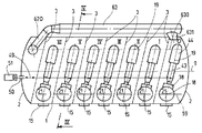
図1〜図7は、溶接された皿形ボイラヘッドにより両面端部で耐圧されて閉じられる円筒形ボイラとして具現化された処理容器1を備えた、高温後染め機の形態の、本発明による機器を示している。図1、図2に示されている例示的実施形態においては、6つのJボックスが処理容器1内に設けられ、I〜VIで識別される。たとえば図1および図4から分かるように、それぞれのJボックスI〜VIは、2つの平行な側壁3と側壁3に接合された1つの底壁4とによって画定される。底壁4は、一般に知られている方法で、平行なPTFEロッドによりまたはPTFEタイルを用いて設計されることにより、滑動する底部として具現化され、両方の種類とも、過剰な処理溶液が、処理容器1内の底壁4の下の、図4に5で印が付けられた室内に流れ出すことができる。布境界壁とも呼ばれる側壁3は、それぞれ、PTFE被覆を有する内側で具現化されるか、または案内形材内の一枚板の部品として具現化され、底壁4と同様に、摩擦を減少させる配置が得られる。内部カバー6(図4)が側壁3に接合され、Jボックスは、ロープ入口開口部7とロープ出口開口部8とを有する、実質的にU形状の設計となる。示されている実施形態におけるJボックスI〜VIは、それぞれ、同じ軸方向のJボックス幅を有し、処理容器については、2200mmの直径が通常800mmとなり得る。
1 to 7 according to the invention in the form of a high temperature post-dyeing machine comprising a
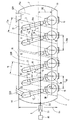
図1〜図3から分かるように、隣接するJボックスI〜VIの側壁3は、処理容器の、9で示されている長手軸に対して斜めに延在し、平面図において、処理容器の長手軸と共に角度10を形成し、これに対応して、12で示されている横断面に対する補角11があり、容器のジャケットの壁に対しておよび処理容器の長手軸9に対して垂直に延在する。実際には、角度11は、約12.5°〜15°程度であるが、図3に13および13aで示されている、処理容器1の寸法および軸方向のJボックス幅によっては、さらに他の角度値も可能である。これについては、以下に詳細に記述する。
As can be seen from FIGS. 1 to 3, the
それぞれのJボックスI〜VIについて、ロープ出口側に、ロープ出口開口部8のやや下に置かれた、1つの充填レベルセンサ14(図4)があり、これは、各Jボックス内のロープを制限するための信号を出力する。
For each J box I-VI, there is one filling level sensor 14 (FIG. 4) located slightly below the
それぞれのJボックスI〜VIにおいて、着脱耐圧ストッパー15を用いて閉じられる取付けおよび取外し用開口部が、処理容器1のほぼ水平直径平面16のレベルに置かれる。処理容器1の裏面に、溶液抜取容器171が設けられ、これは、容器の内部と連通し、液体が繊維物品を出る時に処理剤(液体)を抜き取るためのものである。溶液抜取容器171の内容物として、溶液の総量から、繊維物品に閉じ込められた溶液の割合を引いたものを保持でき、各Jボックス内で移動する物品と物品の外にある溶液の表面とが接触せず、このような状態により、溶液製剤を後に添加することが可能となる。
In each of the J boxes I to VI, an opening for attachment and detachment that is closed using the detachable pressure-
ロープ出口開口部8から間隔を置いて上にある、処理容器1のジャケットに溶接された円筒形のソケットコネクタ17は、それぞれのJボックスI〜VI用の容器内部に通じており、このスタブは、その軸18に垂直に配向され、結合されたJボックスの、図3に19で示されている対称中心面に置かれる。ソケットコネクタ17は、その端部に環状のフランジ20を備え、ブロワーユニット21がこのフランジに装着される。ブロワーユニット21は、垂直回転軸18を中心に循環する放射状のブロワーの羽根車24を含み、かつ上部ハウジング部分22に装着された電動機25に連結された、羽根車ハウジング23を含む上部ハウジング部分22を備える。電動機25は、その回転速度がインバータ操作のために調節され得る、かつ必要な供給流を調節するよう設計された回転電流電動機である。その軸は、軸封26によりハウジング内部から封止される。渦巻き形の案内バッフル27(図5)が、ブロワーハウジング23内に置かれ、ブロワーの羽根車24によって汲み上げられたガス媒体を、回転軸18と同軸の外部流管28内にそらし、これにより、羽根車ハウジング23との圧縮側での連通が確立される。
A
ブロワーユニット21の下部ハウジング部分を形成するソケットコネクタ17内で、わずかな放射状の間隔を有して挿入された、円筒形の内部ジャケット29が、回転可能に支持され、回転軸18と同軸方向に配向される。内部ジャケット29は、その外周が、たとえば溝つきカフとして具現化された封止リップを介して環状のフランジ20から封止され、平らなPTFE形材31を介して環状のフランジ上に懸濁されて放射状に回転可能におよび軸方向に支持される。ジャケット29の回転軸18と同軸方向に、内部流管33が延在しており、これには、吸引管としてブロワーの羽根車の入口へと通じ、かつその対向して対称な位置にある端部で処理容器1の内部に開口する、吸引コーンが設けられる。ジャケット29を備えた内部流管33は、外部流管28の円筒形の延在部28aを画定する。したがって、ブロワーユニット21内に、2つの中央に置かれた、垂直の流れ管28、28a、33が具現化され、吸引管として作用する流れ管33は、円錐形に設計され、内部ジャケット29から底部(図4)で閉じられる。
A cylindrical
ブロワーユニット21全体が、環状のフランジ22から取り外され、必要に応じて、異なる電力のまたは異なる汲み上げ特性を有するブロワーユニットに取り替えられ得る。ソケットコネクタ17および溶接されたフランジとして具現化された環状のフランジ20は同じであるので、ブロワーユニットを取り替える場合には、異なる大きさのブロワーの羽根車24および羽根車23に代えれば良い。
The
同心の軸受けリング34が、形材36(図6)を介して、相対回転しないように固定された形で、回転可能に支持されたジャケット29に接続され、環状のノズルとして具現化された供給ノズル38の円筒の布入口部分37を担持する。布入口部分37は、内部ジャケット29に溶接されておりかつ供給媒体により圧力にさらされる外部流管28と連通するノズルハウジング41内にある環状の隙間を、一般に知られている方法でディフューザ40と共に画定する、入口ノズル部分39に通じている。ノズルハウジング41に隣接するのは、ノズル部分39と同軸でありかつディフューザ40がこの中に吐出するPTFE供給チューブ43のために、好適なストッパーにより、これに固定された支持ハウジング42である。ハウジング42は、隣接する供給チューブ43のための、相対回転しないように固定された強固な支持構築物を形成し、この上には、供給チューブ43と共に供給部分を形成し、かつたとえば出て行くロープをJボックス内に導入し得る、より大きい直径の入口曲線44が設置される。これについては、以下に詳細に記述する。供給チューブ43は、図4に示されている例示的実施形態においては、水平に対して約10°の角度でわずかに上昇する。その入口曲線44は、Jボックスの入口開口部7の縁からわずかな間隔の所で出る。
A
噴射ノズル45が、その軸を中心として環状に分散されており、かつPTFEおよび特別な鋼の布のフレキシブルホース46を介して処理剤供給ライン47に連通する、円筒形のノズルハウジング41内に出る。噴射ノズル45は、ノズル部分39とディフューザ40との間に具現化された環状の隙間の方向に噴霧器ノズルとして作用するので、供給ノズル38を通過するロープに対する処理剤噴射流による均一な作用が達成される。
The injection nozzle 45 exits into a cylindrical nozzle housing 41 which is distributed annularly about its axis and communicates with the treatment
片持ちアーム48が、ノズルハウジング41の裏面に固定され、たとえば図1から分かるように、処理容器1の軸方向の長さに延在し、かつ50で封止されて皿形ボイラヘッド2を通過する、スラストロッド49に関節式に接続される。スラストロッド49は、ねじ込みスピンドルまたは他のいくつかの作動駆動装置に取り替えられる空気圧押上シリンダ51と連通する。したがって、押上シリンダ51の作動により、ブロワーユニットの垂直回転軸18を中心として、供給ノズル38および供給部分43/44が枢転する。たとえば図1および図2に示すように、スラストロッド49がすべてのブロワーユニット21の片持ちアーム48に連結されるので、押上シリンダ51が作動すると、すべてのJボックス用の供給ノズルおよび供給部分は、各垂直枢軸18を中心として同じ角度で同時に枢転され、したがって互いに強固に連結される。図1および図2に0で識別される、中間の収納室内にあり、かつ皿形ボイラヘッド2により一方の側で画定される、さらなるブロワーユニット21の供給ノズル38および供給部分43/44についても同様である。これについても、以下に説明する。
A
処理容器1内のそれぞれの供給ノズル38の布入口部分37の下に、水平軸を中心として自由回転式で支持された偏向ローラ52があり、この偏向ローラ52は、処理容器内のすべてのJボックスに沿って選択的に連続的に延在することもあれば、それぞれのJボックスまたはそれぞれの群のJボックスに自身の偏向ローラ52が設けられることもある。それぞれの偏向ローラ52は、図7に示すように、処理容器1内にあり、かつたとえば電磁継手として具現化された、歯付きベルト駆動装置54に連結されており、その歯付きベルト55は、ガードバッフルで固定されて、処理容器1の外へと延在し、歯車付電動機56によって駆動される。概して、偏向ローラ52は、滑らかな表面を有する。偏向ローラ52には回転速度監視装置が割り当てられ、これにより、ロープ走行を監視することができる。図4に示すように、偏向ローラ52により、駆動されるかせ巻取り機によって補強しなくても、確実な布の走行が可能となる。これにより、布が供給ノズル38内に垂直に入り、ブロワーユニット21と同じ方向に作用する吸引流により、布が入ってくることが補強される。通常、偏向ローラ52は、自由回転である。布が停止した時のための偏向ローラの一時駆動装置は、ロープを自由に引っ張る仕事を有する。これは、自由回転偏向ローラ52を継手53を備えた駆動電動機56に連結することによって達成される。
Below the
図6においては、供給ノズル38内にロープが入ってくる、やや修正された実施形態が示されている。自由回転偏向ローラ52と布の入路37との間には、枢転可能に収められたさらなる自由回転案内ローラ57が設けられる。図6に実線で示されている、上方に枢転される位置においては、案内ローラ57は、ロープの走行に介入しない。点線で示されている位置へと下方に枢転されると、偏向ローラ52の巻き角が拡大し、したがってロープの網目内にまだ残っている溶液の除去が改良され、したがってロープと共に供給ノズル38内に導入される溶液の量が減少する。定格速度に到達する必要がない場合には、任意に、自由回転偏向ローラ52の駆動装置の電源も投入され得る。案内ローラ57の調整は、58で示されている空気圧押上シリンダによって行われる。
In FIG. 6, a slightly modified embodiment is shown in which a rope enters the
図1、図2では、たとえば、すべてのボックスI〜VIおよび中間のボックス0の、結合された供給ノズル38と供給部分43/44とを備えたブロワーユニット21が、容器の長手軸9に平行な共通の垂直面59に垂直枢軸(18)を有して置かれることを示している。したがって、容器の長手軸9からのすべての枢軸18の間隔60(図3)は等しい。その上、既に上述したように、それぞれの供給ノズル38の枢軸18は、結合されたボックスの垂直の中心面19に延在する。隣接する枢軸18の間の間隔61も等しい。それぞれの供給ノズル38の、62で示されている枢角の範囲は、第1の位置において、隣接する供給部分43/44を備えた供給ノズル38が、各JボックスI〜VIの中心面19でおよびこれに平行な平面19aの中間のボックス0内で、枢軸18と交差する、その長手方向の中心軸を有して置かれるよう選択され、これは、側壁3と対向して対称の位置にある側に、結合されたJボックスの長手方向の中心面19と同様に、隣接するJボックスの側壁から、同じ軸方向の間隔を有して延在する。この設定は、図1に示されている。
1 and 2, for example, the
押上シリンダ51の好適な作動によって設定され得る、かつ枢転範囲62の他方の端部にある、供給ノズル38の第2の位置において、結合された供給部分43/44を備えたすべての供給ノズル38が、図1においては左に、特に第1のJボックス内のそれぞれの供給ノズル38の入口曲線44は、隣接する第2のJボックス内の中央で出るまで枢転される。即ち、入口曲線44のロープ出口開口部は、第2のJボックスの長手方向の中心面19の中心点にある。したがって、ロープが、第1のJボックスから各隣接する第2のJボックスへと送られる。
All supply nozzles with a combined
皿形ボイラヘッド2に隣接する、図2および図3の左にあるJボックスVIの供給ノズル38および供給部分43/44は、この枢転された位置において、入口曲線44と共に、円筒のシュート(scray、スキッド)620(図4)に通じており、これは、皿形ボイラヘッド2と、Jボックスのこれに隣接する側壁3との間の室内にあり、そのオリフィスは、この室内へと入ってくる入口曲線44のオリフィスに整列する。復帰シュート620は、処理容器1に沿って延在し、処理容器の外にあり、かつ漏斗部分631を介して中間のJボックス0内の底部から出る、ロープ復帰チューブ63に出る。供給ノズル38および結合された供給部分43/44のこの位置が、図2、図3に示されている。
The
図3から分かるように、枢転範囲63は、これに対応する枢軸18を通って延在する各横断面12と対称的に具現化される。したがって、Jボックスの側壁3の斜めの位置に沿って、図1の設定および図2の設定の両方において、それぞれの供給ノズル38の入口曲線44が、常に各Jボックス内の中央から出ることが達成される。入口曲線44のロープ出口開口部の中心点は、処理容器の長手軸9と平行に延在する、共通の垂直面630に常にある。したがって、図1の設定および図2の両方について、Jボックス内で平らに折り重ねる同じ状態が得られるが、このことは、適切な布の走行に非常に重要なことである。
As can be seen from FIG. 3, the
枢転範囲62は、Jボックスの側壁3の斜めの位置に適合される。これは、平面12、19の間の、図3に示されている角度11の二倍の大きさである。
The pivot range 62 is adapted to the oblique position of the
図3は、同じ処理容器の直径64および同じ軸方向のブロワーの間隔60について、Jボックス幅13または13aに対する枢角62の影響を示している。図面の左側の枢角の範囲62は25°であり、図面の右側の枢転範囲62aは30°である。その結果は、たとえば25°では700mmの定格ボックス幅13となり、30°では800mmの定格ボックス幅13aとなる。したがって、処理容器1の長手軸に平行な、ブロワーユニット21の、または言い換えれば枢軸18の間隔61も、たとえば間隔61の740mmから間隔61aの840mmに増加する。処理容器1の全長に渡って、ブロワーユニット21は、それぞれのブロワーユニットが垂直に置かれた列を形成する。布の入路は、羽根車軸18の領域内の布入口部分37(図4)の裏面にあるので、優れた布の走行性状が生じる。
FIG. 3 shows the effect of pivot angle 62 on J box width 13 or 13a for the same process vessel diameter 64 and the same axial blower spacing 60. FIG. The pivot angle range 62 on the left side of the drawing is 25 °, and the pivot range 62a on the right side of the drawing is 30 °. The result is, for example, a rated box width 13 of 700 mm at 25 ° and a rated box width 13a of 800 mm at 30 °. Therefore, the interval 61 of the
ノズル部分39に対する、ノズル部分39を含む布入口部分37の内側は、PTFEで被覆されるかまたはPTFEを用いて設計される。
The inside of the
図1の動作モードにおいては、個々のJボックスI〜VIは、互いに平行に接続される。それぞれのJボックス内では、エンドレスロープが、結合された供給ノズル38によって循環する。したがって、1本のロープの処理が、Jボックスのそれぞれ1つ内で行われ得る。
In the operation mode of FIG. 1, the individual J boxes I to VI are connected in parallel to each other. Within each J box, an endless rope is circulated by a combined
図2の設定においては、JボックスI〜VIは、操作中互いに直列に接続され、その結果、エンドレスロープを循環させるための循環システムが生じ、このエンドレスロープは、1つのJボックスから各隣接するJボックスに移行し、列内の最後のJボックス6に戻った後、ロープ復帰チューブ63を介して、中間のボックス0に、またそこから、結合された供給ノズルにより第1のJボックスI内に再び導入される。この設定においては、代替形態として、機器は、ロープが、処理容器1または中間のボックス0に入り、最後のJボックスVIから出る、連続システムとして使用され得る。
In the setting of FIG. 2, J-boxes I-VI are connected in series with each other during operation, resulting in a circulation system for circulating endless ropes, which endless ropes are each adjacent from one J-box. After moving to the J box and returning to the last J box 6 in the row, it passes through the
これについては、様々な処理方法の例示的実施形態において、不可欠な部分内の、処理剤などを添加するための、処理方法に必要な追加装置も簡単に示した、図8、図9を参照しながら、以下に簡単に説明する。 In this regard, in the exemplary embodiments of the various processing methods, see also FIG. 8, FIG. 9, which also briefly shows the additional equipment required for the processing method for adding processing agents, etc., in an integral part. However, a brief description will be given below.
図8、図9は、9つのJボックスI〜IXと10のブロワーユニット21とを備えた高温後染め機を極めて概略的に示しており、それぞれが、結合された供給ノズル38とこれに隣接する供給部分43、44とを備え、このうちの供給ノズル38のみが円で表されている。JボックスI〜IXおよび中間のボックス0のそれぞれに、このような1つのユニットが割り当てられる。供給部分43、44は図2の位置にある。即ち、機械は連続循環操作用に設定される。ロープ復帰ライン63は点線で示されている。空気圧シリンダ51は図2の位置にある。処理容器1の内部は、3つの処理区間X、Y、Zに細分され、そのそれぞれが、それぞれ、3つのJボックスI〜IIIと、IV〜VIと、VII〜IXとを含む。3つの処理区間を互いから離す仕切りは、下部部分から処理容器のジャケットまで延在し、かつ封止リップを介してその内側に接続された、ボックスの仕切りとして具現化された、2つのJボックスの側壁300によってもたらされる。ボックスの仕切り300は、最大溶液レベルを超えて上方に延在する。これらは、Jボックス、IIIおよびIVとVIおよびVIIとの間にある。
FIGS. 8 and 9 very schematically show a hot post-dyeing machine with nine J-boxes I to IX and ten
溶液抜取容器171はまた、これに対応する仕切り170により3つの部分容器に細分され、それぞれが、処理区間X、Y、Zの1つに結合される。3つの処理区間X、Y、Zに対応して、3つの処理剤噴射システムが設けられ、そのそれぞれが、1つの溶液フィルタ70と、1つの噴射ポンプ71と、処理溶液を加熱し冷却するための1つの熱交換機72とを含む。73に、熱交換機72の下流の噴射ポンプ71の圧縮側から始まる締切弁が示されており、この締切弁は、処理溶液を、各処理区間X、Y、Zに結合された溶液抜取容器171の一部に戻すためのものである。循環する処理溶液は、結合された噴射ポンプ71により、適合可能な群のJボックス内にある供給ノズル38の各溶液供給ライン47(図4、図7)内に汲み上げられ、結合されたライン内には、処理溶液を前方に走行するための締切弁74がある。処理区間X、Y、Zのそれぞれのための流出固定具が、75で示されている。処理水、未処理水、軟水、および温水(約60℃)用の供給容器77、または処理浴用の初期溶液容器が、それぞれ各締切固定具74を介して、噴射ポンプ71の吸引側に連通する。処理溶液用の、2つの初期溶液および補充溶液容器78も設けられ、そのそれぞれが、締切弁79を介して噴射ポンプ71の吸引側に連通するようにされ得る。締切弁79および結合されたライン接続は、初期溶液および補充溶液容器の1つのみについて示されている。蒸気源が80で示されており、その下流に、凝縮液分流加減器81、減圧弁82、および調整弁83があり、この源により、処理容器1の内部を直接蒸気にさらすことができる。最後に、切換え/締切アーマチャも、噴射ポンプ71の吸引側に、84で示されている。
The
〔実施例1〕
9つのJボックスI〜IXを備えた高温後染め機においては、アルカリ性の過酸化水素漂白が、その後の反応性染色操作のための事前漂白として、格子結束を有する編み木綿製品に実施される。格子製品は、切開されていない、80cmの円筒の幅を有する。表面積の単位当たり重量は190g/m2であり、300g/mの延メートル重量に相当し、ボックスあたり150kgの9倍のバッチ重量にとってこれは、4500mの布の長さについて、1350kgの全バッチに相当する。
[Example 1]
In a high temperature post-dyeing machine with nine J-boxes I-IX, alkaline hydrogen peroxide bleaching is performed on knitted cotton products with lattice bonds as pre-bleaching for subsequent reactive dyeing operations. The lattice product has an 80 cm cylindrical width that is not incised. The weight per unit of surface area is 190 g / m 2 , which corresponds to an extended metric weight of 300 g / m, and for a batch weight of 9 times 150 kg per box, this is a total batch of 1350 kg for a 4500 m fabric length. Equivalent to.
0.8mmの布の厚さについては、このバッチは、5.76m3の体積Vtexおよび6.0m3の基体堆積VSに相当し、これは、4.86m3の中間室体積VZに対応する。80%の平均溶液装填については、この体積は3.89m3となる。 The thickness of 0.8mm of the fabric, the batch corresponds to the substrate deposition VS volume Vtex and 6.0 m 3 of 5.76M 3, which corresponds to the intermediate chamber volume VZ of 4.86M 3 . For an average solution loading of 80%, this volume is 3.89 m 3 .
機械に装填する準備のための、全バッチは、それぞれが1500mの、3つの接続された部片である。 The entire batch, in preparation for loading into the machine, is three connected pieces, each 1500 m.
初期溶液容器77内に、事前漂白用の処理浴が50℃で2500lで設定されている。
In the
浴は、湿潤剤と、32.5%苛性ソーダと、35%過酸化水素と、漂白安定剤の添加剤とを含む。 The bath contains a wetting agent, 32.5% caustic soda, 35% hydrogen peroxide, and a bleach stabilizer additive.
機械に全バッチを装填
空気圧シリンダ51(図2)は、図2の循環システムの位置に入れられる。これはまた、往復運動する綾振りをJボックス幅全体にスラストロッド49にしたがって入口曲線44に伝える制御ユニット85によって起動されるので、供給部分43は、入口曲線44と共に、それぞれのJボックス用のロープパイラとして機能する。装填操作を監視するために、ブロワーユニット21の領域内のすべてのストッパー15が開放される。
Loading the entire batch into the machine Pneumatic cylinder 51 (FIG. 2) is placed in the position of the circulation system of FIG. This is also activated by a control unit 85 that transmits the reciprocating traverse to the
ブロワーユニット21は、ロープの自己吸引用に、布入口37およびノズル部分39を備えて設計されるので、装填操作に前方送り部片またはベルトが不要となる。
The
処理容器1への装填については、3パイルの布からのロープの装填の先端が、JボックスIIIおよびJボックスVIの中間のボックス0のブロワーユニット21のストッパ15で導入され、3パイルの布のロープの終端部が同じストッパーに固定されるので、ロープの終端部は、入った後に固定される。Jボックス0のブロワーユニット21の電源が投入された後、このブロワーユニットは、第1のロープを中に引く。次いで、約5秒の遅延で、JボックスIIIおよびVIのブロワーユニットの電源が投入されるので、3つのロープが、互いに平行に、JボックスI、IV、およびVIIに入る。ボックス内の布の走行を補強するために、入っててくるJボックスの出口側のブロワーもそれぞれ、電源が投入される。次のJボックスのブロワーユニット21は、これに対応する時間だけ遅れて、電源が投入される。
For loading into the
噴射ノズル45(図4)は、初期溶液容器77に開口連通している、適応可能な群のJボックスに接続された、噴射ポンプ71を介して処理溶液にさらされる。
The injection nozzle 45 (FIG. 4) is exposed to the processing solution via an
ロープ状の円筒の布が入ってきた後、関係する様々なブロワーユニット21およびこれらに接続された締切弁74の電源が切られる。JボックスIII、VIまたは中間のボックス0のストッパー15に到達した、入ってきたロープの端部は、各隣接するロープの終端と共に綴じられ、3つの継目を有するエンドレスロープが作られる。ストッパーのそれぞれから、繊維物品が、これに対応するブロワーユニット21に入ってくることが監視されるが、このストッパー15が閉じられる。
After the rope-shaped cylindrical cloth enters, the
ブロワーユニット21および供給部分43/44を循環システム操作に設定し、入口曲線44の綾振りの電源を投入し、ブロワーユニット21および噴射ポンプ72の電源を投入すると、開放された初期溶液容器77から到達した初期溶液浴は、物品全体に均一に分散される。ブロワーユニット21は、400m/分の布循環速度に調節される。
When the
溶液抜取容器17内のレベルを監視することにより、初期溶液浴が弁73、74を介して初期溶液容器77から導入された後に、処理容器1内のレベルが補正される。処理溶液は、60℃で10分間一定に保たれ、次いで、蒸気源80からの直接蒸気の電源を投入すると、6℃/分の勾配で、90℃の処理温度に加熱され、20分間維持される。
By monitoring the level in the
この時間の間、初期溶液容器77内で、第1の水洗浴が、80℃の2500lの浴体積で準備される。
During this time, in the
処理容器1内の処理浴(漂白浴)は、20分後に、換気弁90およびドレン弁75を開放することにより水抜きされ、第1の水洗浴は、噴射ポンプ71を介して、処理区間X、Y、Z内の3群のJボックスのロープ全体に分散される。
The treatment bath (bleaching bath) in the
Jボックス内で滴り落ちる水洗水が溶液抜取容器17に入り、切換え固定具84を介して噴射ポンプ71によって再吸引される。
The washing water dripping in the J box enters the
循環水洗が、5分間維持される。 Circulating water wash is maintained for 5 minutes.
この時間内に、第2の水洗浴が、初期溶液容器77内に、60℃の2500lの水洗水を用いて、過酸化水素の残留濃度に対して製品を中和させるよう酢酸を添加して準備される。第1の水洗浴が水抜きされた後、逆流原理に基づき、第2の水洗浴が3群のJボックスを通って運ばれ、JボックスVII、VIII、およびIXを含む第1の群のボックスから、それぞれ結合された切換え固定具84および噴射ポンプ71を介して、第2の群のJボックスIV、V、VIに出て、これらを通過した後に、第3の群のJボックスI、II、IIIに汲み上げられ、その後ドレンに運ばれる。この逆流過程においては、その後の反応性染色が60℃の一定温度で行われるので、水洗水の温度は60℃で一定に保たれる。
Within this time, the second rinsing bath added acetic acid into the
アルカリ性の過酸化水素漂白が実施された後に計画される3.5%の反応性染色については、60℃の恒温染色の後に、非固定反応性染料が洗い流され、染浴からの残留化学物質が同時に中和される。 For the 3.5% reactive dyeing planned after the alkaline hydrogen peroxide bleaching is performed, after the constant temperature dyeing at 60 ° C., the non-fixed reactive dyes are washed away and the residual chemicals from the dye bath are removed. Neutralized at the same time.
水洗サイクルは、上述した過酸化漂白サイクルより包括的であり、したがってより時間がかかる。 The water wash cycle is more comprehensive than the peroxide bleach cycle described above and is therefore more time consuming.
総処理時間を短縮するために、ボックスは、異なる数のボックス(たとえば1〜4ボックス)の群に分割され得る。そして、水洗部分によって時間をずらすことができるので、水洗部分の順序に基づき、異なる水洗温度および異なる残留濃度を有する水洗浴により、繊維物品に対して同時に作用が及ぼされ得る。 In order to reduce the total processing time, the boxes can be divided into groups of different numbers of boxes (eg 1-4 boxes). And since time can be shifted by the water-washing part, based on the order of the water-washing part, an effect | action can be exerted simultaneously with respect to textile goods by the water-washing bath which has a different water-washing temperature and a different residual density | concentration.
本明細書に一例として記載されている反応性染色における、水洗サイクルの内訳については、50℃の第1の水洗浴および浴循環で、濃度の均一化が達成され、中和のために逆流原理に基づいて50℃の第2の浴が設けられ、次いで、また85℃の水洗温度でずらして使用することにより、温水水洗を行って、残留アルカリを中和し、蒸気源80からの直接蒸気の電源も投入し得る。洗い落としプロセスを加速するために、ボックスの部分内の、入ってくる溶着ロープの表面に向けた、さらなる噴射ノズル(図示せず)の電源が投入される。
Regarding the breakdown of the washing cycle in the reactive dyeing described as an example in the present specification, concentration uniformity is achieved in the first washing bath and bath circulation at 50 ° C., and the reverse flow principle is used for neutralization. A second bath at 50 ° C. is then provided, and then by using a staggered water wash temperature of 85 ° C. to perform warm water wash to neutralize residual alkali and direct steam from the
温水水洗の後の、同じ作業過程の後、逆流原理に基づき、50℃の2つの初期水洗浴溶液および30℃の1つの初期水洗浴溶液が、オフセット接続で実施される。即ち、第1の群のボックスを通過し、第2の群のボックスに切換えられた後に、次のその後の水洗浴が、第1の群のボックスに既に切り換えられている場合がある。 After the same working process after warm water washing, based on the backflow principle, two initial water bath solutions at 50 ° C. and one initial water bath solution at 30 ° C. are carried out in an offset connection. That is, after passing through the first group of boxes and being switched to the second group of boxes, the next subsequent flush bath may already be switched to the first group of boxes.
水洗溶液が最後の水洗浴から水抜きされると、継目センサ87(図4)が継目を報告した後、ロープはボックスIXで停止する。ロープは切り離され、布の走行方向の反対にある部片は、JボックスIXからストッパー15を通って運ばれ、回転往復台内で、吐出かせ巻取り機を介して溶着される。吐出時に空になったJボックスのブロワーユニット21の電源は、自動的に切られる。
When the rinsing solution is drained from the last rinsing bath, the rope stops at box IX after seam sensor 87 (FIG. 4) reports the seam. The rope is cut off, and the piece opposite to the cloth traveling direction is conveyed from the J box IX through the
〔実施例2〕
9つのJボックスを備えた、図9に示されている高温後染め機は、基本的に、図8に示されている高温後染め機に相当する。したがって、同一の部分は、同じ参照符号で識別されるので、再び説明を加えない。図9の機械においては、請求項8に記載の機械に加えて、処理容器1を蒸気源90からの過熱蒸気にさらすための装置、および処理容器1からの蒸気および空気の混合物の吸引抽出用の装置も設けられる。蒸気源90の後には、凝縮液分流加減器91および減圧弁92を介して、双方向固定具95により調整弁94を介して隣接する蒸気過熱器93があり、この固定具により、処理容器内部を、および96で示されている環状の分散を介して、個々のブロワーユニット21の供給ノズル38を、過熱蒸気に選択的にさらすことができる。
[Example 2]
The hot post-dyeing machine shown in FIG. 9 with nine J boxes basically corresponds to the hot post-dyeing machine shown in FIG. Accordingly, the same parts are identified by the same reference numerals and will not be described again. In the machine of FIG. 9, in addition to the machine of
処理容器内部からの空気および蒸気の混合物の吸引抽出器は、熱風冷却器98および気体湿度分離器99を介して処理容器内部と連通する吸引抽出ブロワー97を備える。吸引抽出ブロワー97により、たとえば約0.5絶対バールの最大低圧を生成することができる。
The suction extractor for the mixture of air and steam from the inside of the processing vessel includes a
図9の高温後染め機においては、テクスチャードポリエステルに対する分散染色が、たとえば還元型後洗浄を含む恒温染色の形態で行われ得る。 In the high-temperature after-dyeing machine of FIG. 9, disperse dyeing for the textured polyester can be carried out in the form of isothermal dyeing including, for example, reduction type post-cleaning.
この分散染色については、ポリエステルの編地25%Trevira(登録商標)350および75%Trevira(登録商標)76/1が、特にチューブ幅90cmおよび表面積の単位当たり重量約110g/m2の、織機から出来上がったばかりの円筒の布の形態で使用され、これは、6300mの布の長さについて、1260kgの全バッチにおいて、9掛けるJボックス当たり140kgのバッチ重量に相当する、約200g/mの延メートル重量に対応する。機械に装填する準備のための、全バッチは、それぞれが2100mの長さの、3つの接続された部片である。
For this disperse dyeing, polyester knitted
物品の処理容器1への装填は、実施例1と同じ方法で行われる。
The article is loaded into the
次に、物品は、約500m/分の布の速度で、60℃の温度で、事前洗浄として使用される洗浄溶液に15分間晒される。洗浄溶液が水抜きされた後、およびひとまとめの布を滴り落とすための1.5分間の待ち時間の後、バッチの中間水洗が、初期溶液容器77からの洗浄溶液を用いて、約60℃で行われる。
The article is then exposed for 15 minutes to a cleaning solution used as a pre-clean at a temperature of 60 ° C. at a fabric speed of about 500 m / min. After the wash solution has been drained, and after a 1.5 minute waiting period to drip the batch of cloth, an intermediate wash of the batch is performed at about 60 ° C. using the wash solution from the
その後、化学物質および添加剤を用いて準備され、かつ平均添加剤および酢酸ナトリウムおよびpHを調整するための酢酸を含む処理浴は、86℃に加熱され、中間水洗溶液が水抜きされた後、特に5°/分の勾配で均一に加熱し、蒸気源90からの直接過熱蒸気を添加して、噴射ノズル45を介して走る布に分散され、切換固定具95は、過熱蒸気が処理容器内部に流れ込むように設定される。物品は、染料の噴射温度まで加熱される。この例では、115℃に設定される。
Thereafter, a treatment bath prepared with chemicals and additives and containing the average additive and sodium acetate and acetic acid to adjust the pH is heated to 86 ° C. and the intermediate rinse solution is drained. In particular, heating is performed uniformly at a gradient of 5 ° / min, and superheated steam directly from the
次に、物品の染色は、一般に知られている手順によって行われ、その後、逆流原理に基づき、その後の水洗を含む還元型後洗浄が行われる。水洗溶液の水洗作業および水抜きの結果、ロープは、JボックスIX内の継目で切断され、既に説明した方法で処理容器から除去される。 Next, the dyeing of the article is performed by a generally known procedure, and thereafter, a reduction type post-washing including a subsequent water washing is performed based on the backflow principle. As a result of the rinsing operation and draining of the rinsing solution, the rope is cut at the seam in J box IX and removed from the processing vessel in the manner already described.
〔実施例3〕
図9の高温後染め機を用いて、たとえば編み木綿製品に、既に実施した反応性染色を行った後、および循環システム内での洗浄および水洗の後、その後の染色段階が実施され得る。
Example 3
Using the hot post-dyeing machine of FIG. 9, for example, after the reactive dyeing already carried out on a knitted cotton product and after washing and rinsing in the circulation system, subsequent dyeing steps can be carried out.
このため、以下の処理ステップが、機械内で実施される。 For this, the following processing steps are carried out in the machine.
1.処理容器1およびその中にある構造構成部分を含む、繊維物品の加熱および溶液の装填
1. Heating of fiber articles and loading of solutions, including
ロープの循環に関係するブロワーユニット21の電源が投入され、偏向ローラ52が駆動された後、枢転可能に収められた案内ローラ57は、空気圧シリンダ58(図6)を介してロープを押圧するようにされる。空気圧シリンダ51(図2)によって生成された、入口曲線44の綾振りにより、循環モード用のJボックスI〜IX内のロープの適切な配列が確実となる。
After the power of the
蒸気源80から直接蒸気を送り出すための電源を入れることにより、物品を約110℃の温度まで素早く加熱することができる。約10分後に蒸気の供給が中断され、枢転可能な案内ローラ57が、上方に枢転されて開始位置に戻る。同時に、偏向ローラ52の駆動装置の電源が切られ、ブロワーユニット21の駆動装置が上方に調節されて、400m/分の布循環速度となる。
By turning on the power to deliver steam directly from the
2.物品の湿気を同時に減少させる蒸発段階を作るために、蒸気源30からの過熱を含む直接蒸気が、好適に設定された双方向切換え固定具95を介して、150℃の流入温度で供給ノズル38に切り換えられる。流出固定具75が閉じられると、吸引抽出ブロワー97の電源が投入され、熱風冷却器98は、50℃の出口温度に調節される。この処理ステップは、20分間維持される。
2. In order to create an evaporation stage that simultaneously reduces the moisture of the article, direct steam, including superheat, from the
3.バッチを冷却するために、過熱蒸気が遮断され、換気固定具90が開放された後、吸引抽出ブロワー97を通じて、外気が吸引され、バッチが約40℃まで冷却されることが達成される。
3. In order to cool the batch, after the superheated steam is shut off and the ventilating
次に、ロープが、上述した方法で、JボックスIXで切断され、処理容器1から除去される。
Next, the rope is cut at the J box IX and removed from the
0 中間のボックス
1 処理容器
2 皿形ボイラヘッド
3 側壁
4 底壁
5 室
6 内部カバー
7 ロープ入口開口部
8 ロープ出口開口部
9 長手軸
10 角度
11 補角
12 横断面
13 処理容器の寸法
13a 軸方向のJボックス幅
14 充填レベルセンサ
15 着脱耐圧ストッパー
16 水平直径平面
17 円筒形のソケットコネクタ、溶液抜取容器
18 垂直回転軸
19 対称中心面
20 環状のフランジ
21 ブロワーユニット
22 上部ハウジング部分
23 羽根車ハウジング
24 羽根車
25 電動機
26 軸封
27 案内バッフル
28 外部流管
28a 円筒形の延在部
29 内部ジャケット
30、80、90 蒸気源
31 PTFE形材
32 側壁
33 内部流管
34 軸受けリング
36 形材
37 布入口部分、ロープ入口、入路
38 供給ノズル
39 入口ノズル部分
40 ディフューザ
41 ノズルハウジング
42 支持ハウジング
43 PTFE供給チューブ、供給部分
44 入口曲線、ロープ出口、供給部分、枢転装置
45 噴射ノズル
46 フレキシブルホース
47 処理剤供給ライン
48 片持ちアーム
49 スラストロッド、枢転装置
50 封止
51 空気圧押上シリンダ、枢転装置
52 偏向ローラ
53 継手
54 歯付きベルト駆動装置
55 歯付きベルト
56 歯車付電動機
57 自由回転案内ローラ
58 空気圧押上シリンダ
59 共通の垂直面
60、61 間隔
62 枢角領域
63 ロープ復帰チューブ、ロープ復帰装置
64 処理容器の直径
70 溶液フィルタ
71 噴射ポンプ
72 熱交換機
73、74、79 締切弁
75 流出固定具
77 供給容器
78 補充溶液容器
79 締切弁
81、91 凝縮液分流加減器
82、92 減圧弁
83、94 調整弁
84 切換え/締切アーマチャ
85 制御ユニット
87 継目センサ
90 換気弁
93 蒸気過熱器
95 双方向固定具
96 環状の分散
97 吸引抽出ブロワー
98 熱風冷却器
99 気体湿度分離器
170 仕切り
171 溶液抜取容器、処理剤収集容器
300 側壁
620 シュート、ロープ復帰装置
630 垂直面
631 漏斗部分、ロープ復帰装置
DESCRIPTION OF SYMBOLS 0 Middle box 1 Processing container 2 Dish-type boiler head 3 Side wall 4 Bottom wall 5 Chamber 6 Inner cover 7 Rope inlet opening 8 Rope outlet opening 9 Longitudinal axis 10 Angle 11 Supplemental angle 12 Cross section 13 Processing container dimension 13a Axis Direction J box width 14 Filling level sensor 15 Detachable pressure stopper 16 Horizontal diameter plane 17 Cylindrical socket connector, solution withdrawal container 18 Vertical rotation axis 19 Symmetrical center plane 20 Annular flange 21 Blower unit 22 Upper housing part 23 Impeller housing 24 Impeller 25 Motor 26 Shaft Seal 27 Guide Baffle 28 External Flow Pipe 28a Cylindrical Extension 29 Internal Jacket 30, 80, 90 Steam Source 31 PTFE Shape 32 Side Wall 33 Internal Flow Pipe 34 Bearing Ring 36 Shape 37 Cloth Entrance part, rope entrance, entrance 38 Supply nose 39 Inlet nozzle portion 40 Diffuser 41 Nozzle housing 42 Support housing 43 PTFE supply tube, supply portion 44 Inlet curve, rope outlet, supply portion, pivot device 45 Injection nozzle 46 Flexible hose 47 Treatment agent supply line 48 Cantilever arm 49 Thrust Rod, pivoting device 50 Sealing 51 Pneumatic push-up cylinder, pivoting device 52 Deflection roller 53 Joint 54 Toothed belt drive device 55 Toothed belt 56 Geared motor 57 Free rotation guide roller 58 Pneumatic push-up cylinder 59 Common vertical surface 60 , 61 Interval 62 Pivot region 63 Rope return tube, rope return device 64 Diameter of processing container 70 Solution filter 71 Injection pump 72 Heat exchanger 73, 74, 79 Shutoff valve 75 Outflow fixture 77 Supply container 78 Replenishment solution container 79 Cutoff valve 81, 91 Condensate flow divider 82, 92 Pressure reducing valve 83, 94 Adjusting valve 84 Switching / cutoff armature 85 Control unit 87 Seam sensor 90 Ventilation valve 93 Steam superheater 95 Bidirectional fixture 96 Annular dispersion 97 Suction extraction Blower 98 Hot air cooler 99 Gas humidity separator 170 Partition 171 Solution extraction container, treatment agent collection container 300 Side wall 620 Chute, rope return device 630 Vertical surface 631 Funnel portion, rope return device
Claims (29)
送り方向の駆動動作が、供給ノズル手段を介して前記ロープに作用するようにされた供給媒体のガス流により、前記繊維物品に伝えられ、
前記繊維物品が、それぞれのJボックスに入る前に、該Jボックスに割り当てられた別個の供給ノズル手段を通過し、該供給ノズル手段から出る時に、前記各連関した第1のJボックスまたは該Jボックスに隣接する第2のJボックス内に選択的に導入され、または少なくとも1つのJボックスの場合には、該Jボックスから離れた方に前記繊維物品を運ぶ所定の経路に沿って導かれる、方法。 A method of processing a rope-like fiber article in a closed container comprising at least two axially adjacent J-boxes for receiving the fiber article during at least a portion of the processing time,
Drive action in the feed direction is transmitted to the textile article by the gas flow of the supply medium adapted to act on the rope via the supply nozzle means,
When the textile article passes through separate supply nozzle means assigned to the J box before leaving the J box and exits the supply nozzle means, each associated first J box or J Selectively introduced into a second J box adjacent to the box or, in the case of at least one J box, guided along a predetermined path carrying the textile article away from the J box; Method.
閉鎖可能な処理容器(1)と、
処理時間の少なくとも一部の間、前記繊維物品を受けるための前記処理容器内に横に並んで置かれた、少なくとも2つのJボックス(I〜VI)と、
送り動作を前記繊維物品に伝えるガス供給媒体によって作用を受け得る、ロープ入口(37)とロープ出口(44)とを有する、前記繊維物品を通過させる供給ノズル手段(38)を備えた、前記繊維物品を送るための供給手段と、
前記処理容器(1)内で処理剤を前記繊維物品に作用させるための装置(45、46)と
を備えた機器であって、
それぞれのJボックス(I〜VI)に、自身の供給ノズル手段(38)が割り当てられ、ロープ出口(44)が、各連関した第1のJボックス内に、または少なくとも1つのJボックスから該Jボックスに隣接する第2のJボックス内に、または出ていくロープを受ける装置(620)内に選択的に通じるように、前記供給ノズル手段が調整可能に具現化された機器。 Equipment for processing rope-like fiber articles,
A closable treatment container (1);
At least two J-boxes (I-VI) placed side by side in the processing vessel for receiving the textile article for at least part of the processing time;
The fiber comprising supply nozzle means (38) for passing the textile article, having a rope inlet (37) and a rope outlet (44), which can be acted upon by a gas supply medium that conveys a feeding action to the textile article Supply means for sending the goods;
An apparatus including a device (45, 46) for causing a treatment agent to act on the fiber article in the treatment container (1),
Each J box (I-VI) is assigned its own supply nozzle means (38), and a rope outlet (44) is connected to the J in each associated first J box or from at least one J box. An instrument in which the supply nozzle means is embodied in an adjustable manner so as to selectively lead into a second J box adjacent to the box or into a device (620) for receiving the outgoing rope.
Priority Applications (1)
| Application Number | Priority Date | Filing Date | Title |
|---|---|---|---|
| JP2005364792A JP2007169802A (en) | 2005-12-19 | 2005-12-19 | Method and device for treating rope-like fiber product |
Applications Claiming Priority (1)
| Application Number | Priority Date | Filing Date | Title |
|---|---|---|---|
| JP2005364792A JP2007169802A (en) | 2005-12-19 | 2005-12-19 | Method and device for treating rope-like fiber product |
Publications (1)
| Publication Number | Publication Date |
|---|---|
| JP2007169802A true JP2007169802A (en) | 2007-07-05 |
Family
ID=38296728
Family Applications (1)
| Application Number | Title | Priority Date | Filing Date |
|---|---|---|---|
| JP2005364792A Withdrawn JP2007169802A (en) | 2005-12-19 | 2005-12-19 | Method and device for treating rope-like fiber product |
Country Status (1)
| Country | Link |
|---|---|
| JP (1) | JP2007169802A (en) |
-
2005
- 2005-12-19 JP JP2005364792A patent/JP2007169802A/en not_active Withdrawn
Similar Documents
| Publication | Publication Date | Title |
|---|---|---|
| US3921420A (en) | Apparatus for wet processing of textile materials | |
| TWI464312B (en) | Method and apparatus for processing rope textiles | |
| US7398574B2 (en) | Method and apparatus for treating ropelike textile goods | |
| US7578152B2 (en) | Wet processing or finishing machine for rope-formed textile products | |
| US10895031B2 (en) | Method for the treatment of a textile substrate, and devices for carrying out said method | |
| WO1997004157A1 (en) | Draft-type processing device and processing method | |
| US20060253999A1 (en) | Method and apparatus for treating textile goods in rope form | |
| US3330134A (en) | Apparatus for the fluid treatment of textiles | |
| KR20060128719A (en) | Method and apparatus for uniform application of treatment agent to a textile rope | |
| US4716744A (en) | Apparatus for wet treatment of cloth in endless rope form | |
| US4001945A (en) | Wet processing means | |
| CN107794657A (en) | A kind of energy-saving dyeing machine | |
| JP2007169802A (en) | Method and device for treating rope-like fiber product | |
| US20210156077A1 (en) | Apparatus for decoloring or treating manufactured articles | |
| CN208055628U (en) | A kind of energy-saving dyeing machine | |
| JP2980989B2 (en) | Airflow type processing apparatus and processing method | |
| CN216427623U (en) | Spray even jet dyeing device | |
| JPH07305261A (en) | Fiber product-treating apparatus | |
| US6343395B1 (en) | Apparatus and process for wet-processing of textile material | |
| KR100986144B1 (en) | Dyeing machine | |
| TWI323302B (en) | Wet processing or finishing machine for rope-formed textile products | |
| JPH08117714A (en) | Cleaning device for inside of air current circulation path in air current type treating machine | |
| US3409919A (en) | Process for treating textile material sequentially in a series of liquid treatments | |
| JPH08269863A (en) | Washing method in ropy textile product processing apparatus and washing device | |
| JP2006207041A (en) | Wet treatment machine of string-shaped fiber product |
Legal Events
| Date | Code | Title | Description |
|---|---|---|---|
| A621 | Written request for application examination |
Free format text: JAPANESE INTERMEDIATE CODE: A621 Effective date: 20081205 |
|
| A761 | Written withdrawal of application |
Free format text: JAPANESE INTERMEDIATE CODE: A761 Effective date: 20100628 |
|
| A521 | Written amendment |
Free format text: JAPANESE INTERMEDIATE CODE: A821 Effective date: 20100628 |