JP2007166364A - Display, display control method, program, and recording medium - Google Patents
Display, display control method, program, and recording medium Download PDFInfo
- Publication number
- JP2007166364A JP2007166364A JP2005361346A JP2005361346A JP2007166364A JP 2007166364 A JP2007166364 A JP 2007166364A JP 2005361346 A JP2005361346 A JP 2005361346A JP 2005361346 A JP2005361346 A JP 2005361346A JP 2007166364 A JP2007166364 A JP 2007166364A
- Authority
- JP
- Japan
- Prior art keywords
- display
- connector portion
- connector
- input
- video signal
- Prior art date
- Legal status (The legal status is an assumption and is not a legal conclusion. Google has not performed a legal analysis and makes no representation as to the accuracy of the status listed.)
- Pending
Links
Images

Landscapes
- Transforming Electric Information Into Light Information (AREA)
- Control Of Indicators Other Than Cathode Ray Tubes (AREA)
- Controls And Circuits For Display Device (AREA)
- Devices For Indicating Variable Information By Combining Individual Elements (AREA)
Abstract
【課題】ディスプレイ同士を容易に接続する。
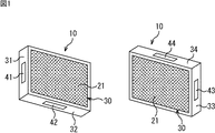
【解決手段】直方体状の筐体10の1つの面30に映像を表示する表示部21が設けられている。面30に直交する4つの側面のうちの左側面31には、左コネクタ部41が設けられており、左コネクタ部41には、外部から、映像信号が入力される。また、左側面31と対向する右側面33には、右コネクタ部43が設けられており、右コネクタ部43からは、外部に、映像信号が出力される。本発明は、例えば、マルチディスプレイシステムを構成するディスプレイに適用できる。
【選択図】図1An object of the present invention is to easily connect displays.
A display unit 21 that displays an image on one surface 30 of a rectangular parallelepiped housing 10 is provided. A left connector portion 41 is provided on the left side surface 31 among four side surfaces orthogonal to the surface 30, and a video signal is input to the left connector portion 41 from the outside. A right connector portion 43 is provided on the right side surface 33 facing the left side surface 31, and a video signal is output from the right connector portion 43 to the outside. The present invention can be applied to, for example, a display constituting a multi-display system.
[Selection] Figure 1
Description
本発明は、ディスプレイ、ディスプレイの制御方法、プログラム、並びに記録媒体に関し、特に、例えば、ディスプレイ同士を容易に接続することができるようにするディスプレイ、ディスプレイの制御方法、プログラム、並びに記録媒体に関する。 The present invention relates to a display, a display control method, a program, and a recording medium. More particularly, the present invention relates to a display, a display control method, a program, and a recording medium that can easily connect displays.
例えばCRT(Cathode Ray Tube)や液晶パネル等の表示手段を有する複数のディスプレイ同士を接続することで形成されたマルチディスプレイシステムが知られている。マルチディスプレイシステムとは、例えば、複数の直方体状のディスプレイを、水平方向にn個、垂直方向にm個のn個×m個並べて配置して相互に接続したものであり、かかるマルチディスプレイシステムでは、例えば全体として1つの映像が表示される(例えば、特許文献1参照)。
ところで、従来のマルチディスプレイシステムにおいては、ディスプレイと他のディスプレイとを電気的に接続するために、ディスプレイにケーブルを装着する作業(ディスプレイ同士をケーブルで繋ぐ作業)が必要であった。また、ディスプレイの配置を変更した場合に、マルチディスプレイシステム全体として適正な映像を表示させるために、ケーブルを装着し直す作業が必要になることがあった。 By the way, in the conventional multi-display system, in order to electrically connect a display and another display, the operation | work which attaches a cable to a display (operation | work which connects displays with a cable) was required. In addition, when the arrangement of the display is changed, it is sometimes necessary to reattach the cable in order to display an appropriate image as the entire multi-display system.
本発明は、このような状況に鑑みてなされたものであり、ディスプレイ同士を容易に接続することができるようにするものである。 This invention is made | formed in view of such a condition, and enables it to connect displays easily.
本発明の第1の側面は、映像を表示する表示手段が1つの面に設けられた直方体状の筐体を有するディスプレイにおいて、前記表示手段が設けられた面に直交する前記筐体の4つの側面のうちの第1の側面に設けられた、外部から、少なくとも映像信号が入力される第1のコネクタ部と、前記第1の側面と対向する第2の側面に設けられた、外部に、少なくとも映像信号を出力する第2のコネクタ部とを備えるディスプレイである。 According to a first aspect of the present invention, there is provided a display having a rectangular parallelepiped casing on which one display unit for displaying an image is provided, and the four casings orthogonal to the plane on which the display unit is provided. The first connector part provided on the first side surface of the side surfaces, to which at least the video signal is input from the outside, and provided on the second side surface opposite to the first side surface, And a second connector unit that outputs at least a video signal.
前記ディスプレイの第1の側面と、他のディスプレイの第2の側面とが対向するように、前記ディスプレイと前記他のディスプレイとが配置されたとき、前記ディスプレイの第1のコネクタ部と、前記他のディスプレイの第2の側面に設けられた第2のコネクタ部とが電気的に接続され、前記ディスプレイの第2の側面に、他のディスプレイの第1の側面が対向するように、前記ディスプレイと前記他のディスプレイとが配置されたとき、前記ディスプレイの第2のコネクタ部と前記他のディスプレイの第1の側面に設けられた第1のコネクタ部とが電気的に接続される。 When the display and the other display are arranged so that the first side surface of the display and the second side surface of the other display face each other, the first connector portion of the display and the other And the second connector portion provided on the second side surface of the display, and the second side surface of the display is opposed to the first side surface of the other display. When the other display is disposed, the second connector portion of the display is electrically connected to the first connector portion provided on the first side surface of the other display.
前記第1のコネクタ部には、映像信号が無線で入力され、前記第2のコネクタ部には、映像信号を無線で出力させることができる。 A video signal can be input to the first connector unit wirelessly, and a video signal can be output to the second connector unit wirelessly.
前記第1のコネクタ部には、放送用の高周波信号、音声信号、または制御信号も入力され、前記第2のコネクタ部からは、放送用の高周波信号、音声信号、または制御信号も出力させることができる。 The first connector unit also receives a broadcast high-frequency signal, audio signal, or control signal, and the second connector unit also outputs a broadcast high-frequency signal, audio signal, or control signal. Can do.
ディスプレイには、前記筐体の4つの側面のうちの前記第1および前記第2の側面以外の第3の側面に設けられた、外部から、少なくとも映像信号が入力される第3のコネクタ部と、前記第3の側面と対向する第4の側面に設けられた、外部に、少なくとも、映像信号を出力する第4のコネクタ部と、前記第1のコネクタ部または前記第3のコネクタ部に入力される映像信号のうちのいずれかを選択し、前記第2のコネクタ部および前記第4のコネクタ部から外部に出力させる選択手段とをさらに設けることができる。 The display includes a third connector portion provided on a third side surface other than the first and second side surfaces of the four side surfaces of the housing, to which at least a video signal is input from the outside. , Provided on the fourth side surface facing the third side surface, and externally input to at least a fourth connector unit for outputting a video signal and the first connector unit or the third connector unit. Selection means for selecting any one of the video signals to be output and outputting the selected video signal to the outside from the second connector portion and the fourth connector portion can be further provided.
ディスプレイには、前記第1または前記第3のコネクタ部に、他のディスプレイが接続されているか否かを判定する判定手段をさらに設けることができる。この場合、前記選択手段には、前記他のディスプレイが接続されているか否かの判定結果に応じて、前記第1または前記第3のコネクタ部に入力される映像信号のうちのいずれかを選択させることができる。 The display may further include determination means for determining whether another display is connected to the first or third connector portion. In this case, the selection means selects one of the video signals input to the first or third connector unit according to a determination result of whether or not the other display is connected. Can be made.
本発明の第2の側面は、映像を表示する表示手段が1つの面に設けられた直方体状の筐体と、前記表示手段が設けられた面に直交する前記筐体の4つの側面のうちの第1の側面に設けられた、外部から、少なくとも映像信号が入力される第1のコネクタ部と、前記第1の側面と対向する第2の側面に設けられた、外部に、少なくとも映像信号を出力する第2のコネクタ部と、前記筐体の4つの側面のうちの前記第1および前記第2の側面以外の第3の側面に設けられた、外部から、少なくとも映像信号が入力される第3のコネクタ部と、前記第3の側面と対向する第4の側面に設けられた、外部に、少なくとも、映像信号を出力する第4のコネクタ部とを備えるディスプレイの制御方法、またはディスプレイを制御するコンピュータに実行させるプログラムであって、前記第1または前記第3のコネクタ部に、他のディスプレイが接続されているか否かを判定し、前記他のディスプレイが接続されているか否かの判定結果に応じて、前記第1または前記第3のコネクタ部に入力される映像信号のうちのいずれかを選択し、前記第2のコネクタ部および前記第4のコネクタ部から外部に出力させるステップを含むディスプレイの制御方法、またはプログラムである。 According to a second aspect of the present invention, there is provided a rectangular parallelepiped housing provided with display means for displaying an image on one surface, and four side surfaces of the housing orthogonal to the surface provided with the display means. And at least a video signal externally provided at a first connector portion to which at least a video signal is input from the outside, and a second side surface opposed to the first side surface. And at least a video signal is input from the outside provided on the third side surface other than the first and second side surfaces of the four side surfaces of the housing. A display control method comprising: a third connector unit; and a fourth connector unit that is provided on a fourth side surface facing the third side surface and outputs at least a video signal. Executed on the computer to control And determining whether or not another display is connected to the first or third connector unit, and depending on the determination result whether or not the other display is connected, A display control method including a step of selecting any one of video signals input to the first or third connector unit and outputting the selected video signal to the outside from the second connector unit and the fourth connector unit. Or a program.
プログラムは、記録媒体に記録することができる。 The program can be recorded on a recording medium.
本発明の第1の側面においては、前記表示手段が設けられた面に直交する前記筐体の4つの側面のうちの第1の側面に設けられた第1のコネクタ部には、外部から、少なくとも映像信号が入力され、前記第1の側面と対向する第2の側面に設けられた第2のコネクタ部からは、外部に、少なくとも映像信号が出力される。 In the first aspect of the present invention, the first connector portion provided on the first side surface of the four side surfaces of the housing orthogonal to the surface on which the display means is provided is externally provided. At least a video signal is input, and at least the video signal is output to the outside from the second connector portion provided on the second side surface facing the first side surface.
本発明の第2の側面においては、前記第1または前記第3のコネクタ部に、他のディスプレイが接続されているか否かが判定される。そして、前記他のディスプレイが接続されているか否かの判定結果に応じて、前記第1または前記第3のコネクタ部に入力される映像信号のうちのいずれかが選択され、前記第2のコネクタ部および前記第4のコネクタ部から外部に出力される。 In the second aspect of the present invention, it is determined whether another display is connected to the first or third connector portion. Then, either one of the video signals input to the first or the third connector unit is selected according to a determination result of whether or not the other display is connected, and the second connector Part and the fourth connector part.
本発明によれば、ディスプレイ同士を容易に接続することができる。 According to the present invention, displays can be easily connected to each other.
以下に本発明の実施の形態を説明するが、本発明の構成要件と、明細書又は図面に記載の実施の形態との対応関係を例示すると、次のようになる。この記載は、本発明をサポートする実施の形態が、明細書又は図面に記載されていることを確認するためのものである。従って、明細書又は図面中には記載されているが、本発明の構成要件に対応する実施の形態として、ここには記載されていない実施の形態があったとしても、そのことは、その実施の形態が、その構成要件に対応するものではないことを意味するものではない。逆に、実施の形態が構成要件に対応するものとしてここに記載されていたとしても、そのことは、その実施の形態が、その構成要件以外の構成要件には対応しないものであることを意味するものでもない。 Embodiments of the present invention will be described below. Correspondences between the constituent elements of the present invention and the embodiments described in the specification or the drawings are exemplified as follows. This description is intended to confirm that the embodiments supporting the present invention are described in the specification or the drawings. Therefore, even if there is an embodiment which is described in the specification or the drawings but is not described here as an embodiment corresponding to the constituent elements of the present invention, that is not the case. It does not mean that the form does not correspond to the constituent requirements. Conversely, even if an embodiment is described here as corresponding to a configuration requirement, that means that the embodiment does not correspond to a configuration requirement other than the configuration requirement. It's not something to do.
本発明の第1の側面は、映像を表示する表示手段(例えば、図1の表示部21)が1つの面に設けられた直方体状の筐体(例えば、図1の筐体10)を有するディスプレイにおいて、前記表示手段が設けられた面に直交する前記筐体の4つの側面のうちの第1の側面に設けられた、外部から、少なくとも映像信号が入力される第1のコネクタ部(例えば、図1の左コネクタ部41)と、前記第1の側面と対向する第2の側面に設けられた、外部に、少なくとも映像信号を出力する第2のコネクタ部(例えば、図1の右コネクタ部43)とを備えるディスプレイである。
The first aspect of the present invention has a rectangular parallelepiped housing (for example, the
ディスプレイには、前記筐体の4つの側面のうちの前記第1および前記第2の側面以外の第3の側面に設けられた、外部から、少なくとも映像信号が入力される第3のコネクタ部(例えば、図1の下コネクタ部42)と、前記第3の側面と対向する第4の側面に設けられた、外部に、少なくとも、映像信号を出力する第4のコネクタ部(例えば、図1の上コネクタ部44)と、前記第1のコネクタ部または前記第3のコネクタ部に入力される映像信号のうちのいずれかを選択し、前記第2のコネクタ部および前記第4のコネクタ部から外部に出力させる選択手段(例えば、図5のクロスポイントスイッチャ316)とをさらに設けることができる。
The display is provided with a third connector portion (at least a video signal input from the outside) provided on a third side surface other than the first and second side surfaces of the four side surfaces of the housing. For example, a
ディスプレイには、前記第1または前記第3のコネクタ部に、他のディスプレイが接続されているか否かを判定する判定手段(例えば、図5のMPU311)をさらに設けることができる。この場合、前記選択手段には、前記他のディスプレイが接続されているか否かの判定結果に応じて、前記第1または前記第3のコネクタ部に入力される映像信号のうちのいずれかを選択させることができる。
The display can further be provided with determination means (for example,
本発明の第2の側面の制御方法、またはプログラムは、映像を表示する表示手段が1つの面に設けられた直方体状の筐体と、前記表示手段が設けられた面に直交する前記筐体の4つの側面のうちの第1の側面に設けられた、外部から、少なくとも映像信号が入力される第1のコネクタ部(例えば、図1の左コネクタ部41)と、前記第1の側面と対向する第2の側面に設けられた、外部に、少なくとも映像信号を出力する第2のコネクタ部(例えば、図1の右コネクタ部43)と、前記筐体の4つの側面のうちの前記第1および前記第2の側面以外の第3の側面に設けられた、外部から、少なくとも映像信号が入力される第3のコネクタ部(例えば、図1の下コネクタ部42)と、前記第3の側面と対向する第4の側面に設けられた、外部に、少なくとも、映像信号を出力する第4のコネクタ部(例えば、図1の上コネクタ部44)とを備えるディスプレイの制御方法、またはディスプレイを制御するコンピュータに実行させるプログラムであり、前記第1または前記第3のコネクタ部に、他のディスプレイが接続されているか否かを判定し(例えば、図6のステップS2およびステップS4の処理を実行する図5のMPU311)、前記他のディスプレイが接続されているか否かの判定結果に応じて、前記第1または前記第3のコネクタ部に入力される映像信号のうちのいずれかを選択し、前記第2のコネクタ部および前記第4のコネクタ部から外部に出力させる(例えば、図6のステップS3およびステップS5の処理を実行する図5のMPU311)ステップを含む。
The control method or program according to the second aspect of the present invention includes a rectangular parallelepiped housing provided with display means for displaying an image on one surface, and the housing orthogonal to the surface provided with the display means. The first connector part (for example, the
以下、図面を参照して本発明を適用した実施の形態について説明する。 Embodiments to which the present invention is applied will be described below with reference to the drawings.
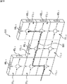
図1は、本発明を適用したディスプレイの一実施の形態の構成例の外観を示す斜視図である。 FIG. 1 is a perspective view showing an appearance of a configuration example of an embodiment of a display to which the present invention is applied.
ディスプレイは、映像を表示する表示部21が1つの面30に設けられた直方体状の筐体10を有する。表示部21は、例えば、CRTや液晶パネル等で構成され、その表示画面は面30とほぼ一致している。ここで面30を、以下適宜、表示面30ともいう。
The display has a
筐体10において、表示面30に直交する4つの側面31,32,33,34のうちの1つの面である、例えば、向かって左側の左側面31には、外部から、放送用の高周波信号(RF(Radio Frequency)信号)、(ベースバンドの)映像信号、(ベースバンドの)音声信号、および制御信号が入力される左コネクタ部41が設けられている。また、左側面31に対向する右側面33には、外部に、放送用の高周波信号、映像信号、音声信号、および制御信号を出力する右コネクタ部43が設けられている。
In the
さらに、4つの側面31乃至34のうちの左側面31および右側面33以外の側面の1つである、例えば、下側面32には、外部から、放送用の高周波信号、映像信号、音声信号、および制御信号が入力される下コネクタ部42が設けられている。また、下側面32に対向する上側面34には、外部に、放送用の高周波信号、映像信号、音声信号、および制御信号を出力する上コネクタ部43が設けられている。なお、以下、映像信号が入力される左コネクタ部41および下コネクタ部42を入力コネクタ部ともいい、映像信号が出力される右コネクタ部43および上コネクタ部44を出力コネクタ部ともいう。
Further, one of the four
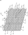
図2は、本発明を適用したマルチディスプレイシステム101の外観構成例を示す斜視図である。
FIG. 2 is a perspective view showing an external configuration example of the
図2において、マルチディスプレイシステム101は、9台のディスプレイ111,1、111,2、111,3、112,1、112,2、112,3、113,1、113,2、113,3を、横×縦が3×3となるように配置して構成されている。
In FIG. 2, the
ここで、ディスプレイ11i,jのサフィックスijは、そのディスプレイ11i,jが、マルチディスプレイシステム101において、第i行第j列(下からi行目で、左からj列目)に配置されているものであることを示す。
Here, the
ディスプレイ11i,jは、図1のディスプレイと同一構成のディスプレイである。
The
なお、ディスプレイ11i,jの各部には、図1のディスプレイの対応する各部に付した符号にサフィクスijを付加した符号を付してある。また、ディスプレイ11i,jを特に区別する必要がなければ、ディスプレイ11と称する。
Note that each part of the
図3は、ディスプレイ11i,jの出力コネクタ部および入力コネクタ部の構成例を示す平面図である。
FIG. 3 is a plan view illustrating a configuration example of the output connector portion and the input connector portion of the
図3の左の図は、出力コネクタ部(右コネクタ部43i,jと上コネクタ部44i,j)の構成例を示している。
The left diagram in FIG. 3 shows a configuration example of the output connector portion (the
出力コネクタ部は、放送用の高周波信号が出力される1つのRF出力端子151、映像信号が出力される3つの映像出力端子152A乃至映像出力端子152C(例えば、RCA端子)、左チャンネルの音声信号が出力される3つの音声出力端子153A乃至音声出力端子153C、右チャンネルの音声信号が出力される3つの音声出力端子154A乃至音声出力端子154C、並びに制御信号が入出力される1つの制御端子155(例えば、IEEE(Institute of Electrical and Electronic Engineers)1394に準拠した端子)で構成される。また、出力コネクタ部には、電源となる電力を外部に供給する電源端子がさらに設けられてもよい。なお、以下、これらの信号端子を出力端子と総称する。
The output connector section includes one
図3の右の図は、入力コネクタ部(左コネクタ部41i,jと下コネクタ部42i,j)の構成例を示している。
The right figure of FIG. 3 shows a configuration example of the input connector portion (the
入力コネクタ部は、放送用の高周波信号が入力される1つのRF入力端子161、映像信号が入力される3つの映像入力端子162A乃至映像入力端子162C(例えば、RCA端子)、左チャンネルの音声信号が入力される3つの音声入力端子163A乃至音声入力端子163C、右チャンネルの音声信号が入力される3つの音声入力端子164A乃至音声入力端子164C、並びに制御信号が入出力される制御端子165(例えば、IEEE1394に準拠した端子)で構成される。また、入力コネクタ部には、電源となる電力が外部から供給される電源端子がさらに設けられてもよい。なお、以下、これらの信号端子を入力端子と総称する。
The input connector unit includes one
出力コネクタ部の出力端子と、入力コネクタ部の入力端子とは、鏡像の関係になるようにそれぞれ配置されている。 The output terminal of the output connector section and the input terminal of the input connector section are arranged so as to have a mirror image relationship.
また、出力コネクタ部と入力コネクタ部とについては、例えば、図2のマルチディスプレイシステム101のように、ある2つのディスプレイ11i,jとディスプレイ11i,j+1とが、それぞれ左側と右側に隣接するように配置された場合に、左側のディスプレイ11i,jの出力コネクタ部としての右コネクタ部43i,jの対応する出力端子と、右側の他のディスプレイ11i,j+1の入力コネクタ部としての左コネクタ部41i,j+1の対応する入力端子とが電気的に接続されるようになっている。
As for the output connector portion and the input connector portion, for example, as in the
すなわち、右コネクタ部43i,jのRF出力端子151と、左コネクタ部41i,j+1のRF入力端子161とが接続され、右コネクタ部43i,jの映像出力端子152Aと、左コネクタ部41i,j+1の映像入力端子162Aとが接続される。また、右コネクタ部43i,jの映像出力端子152Bと、左コネクタ部41i,j+1の映像入力端子162Bとが接続され、右コネクタ部43i,jの映像出力端子152Cと、左コネクタ部41i,j+1の映像入力端子162Cとが接続される。同様に、右コネクタ部43i,jの音声出力端子153A乃至音声出力端子153C、音声出力端子154A乃至音声出力端子154C、または制御端子155と、左コネクタ部41i,j+1の音声入力端子163A乃至音声入力端子163C、音声入力端子164A乃至音声入力端子164C、または制御端子165とが、それぞれ接続される。
That is, the
従って、例えば、右側のディスプレイ11i,j+1に注目すると、そのディスプレイ11i,j+1の左側面31i,j+1に、他のディスプレイ11i,jの右側面33i,jが対向するように、他のディスプレイ11i,jが配置された場合、他のディスプレイ11i,jの右側面33i,jに設けられた右コネクタ部43i,jの出力端子が出力する信号が、注目しているディスプレイ11i,j+1の左側面31i,j+1に設けられた左コネクタ部41i,j+1の入力端子に入力される。
Thus, for example, the right side of the
また、例えば、左側のディスプレイ11i,jに注目すると、そのディスプレイ11i,jの右側面33i,jに、他のディスプレイ11i,j+1の左側面31i,j+1が対向するように、他のディスプレイ11i,j+1が配置された場合、注目しているディスプレイ11i,jの右側面33i,jに設けられた右コネクタ部43i,jの出力端子が出力する信号が、他のディスプレイ11i,j+1の左側面31i,j+1に設けられた左コネクタ部41i,j+1の入力端子に入力される。
Further, for example, the left side of the
さらに、下側と上側に隣接するようにそれぞれ配置された2つのディスプレイ11i,jとディスプレイ11i+1,jについては、下側の11i,jの出力コネクタ部としての上コネクタ部44i,jの出力端子と、上側のディスプレイ11i+1,jの入力コネクタ部としての下コネクタ部42i+1,jの対応する入力端子とが電気的に接続される。
Further, for the two
すなわち、上コネクタ部44i,jのRF出力端子151と、下コネクタ部42i+1,jのRF入力端子161とが接続され、上コネクタ部44i,jの映像出力端子152Aと、下コネクタ部42i+1,jの映像入力端子162Aとが接続される。また、上コネクタ部44i,jの映像出力端子152Bと、下コネクタ部42i+1,jの映像入力端子162Bとが接続され、上コネクタ部44i,jの映像出力端子152Cと、下コネクタ部42i+1,jの映像入力端子162Cとが接続される。同様に、上コネクタ部44i,jの音声出力端子153A乃至音声出力端子153C、音声出力端子154A乃至音声出力端子154C、または制御端子155と、下コネクタ部42i+1,jの音声入力端子163A乃至音声入力端子163C、音声入力端子164A乃至音声入力端子164C、または制御端子165とが、それぞれ接続される。
That is, the
従って、例えば、上側のディスプレイ11i+1,jに注目すると、そのディスプレイ11i+1,jの下側面32i+1,jに、他のディスプレイ11i,jの上側面34i,jが対向するように、他のディスプレイ11i,jが配置された場合、他のディスプレイ11i,jの上側面34i,jに設けられた上コネクタ部44i,jの出力端子が出力する信号が、注目しているディスプレイ11i+1,jの下側面32i+1,jに設けられた下コネクタ部42i+1,jの入力端子に入力される。
Therefore, for example, when attention is paid to the
また、例えば、下側のディスプレイ11i,jに注目すると、そのディスプレイ11i,jの上側面34i,jに、他のディスプレイ11i+1,jの下側面32i+1,jが対向するように、他のディスプレイ11i+1,jが配置された場合、注目しているディスプレイ11i,jの上側面34i,jに設けられた上コネクタ部44i,jの出力端子が出力する信号が、他のディスプレイ11i+1,jの下側面32i+1,jに設けられた下コネクタ部42i+1,jの入力端子に入力される。
Further, for example, the lower side of the
このように、ディスプレイ11i,jは、他のディスプレイと並べて配置するだけで、その他のディスプレイと電気的に接続されるため、ディスプレイ同士の接続を容易に行うことができる。
In this way, the
また、ディスプレイ同士の間での信号の入出力は、上述のように入力端子と出力端子とを直接に接続して行う他、無線通信によって行うことも可能である。 Further, input / output of signals between the displays can be performed by wireless communication in addition to directly connecting the input terminal and the output terminal as described above.
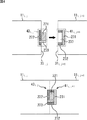
すなわち、図4は出力コネクタ部と入力コネクタ部の他の構成例を示す断面図である。 That is, FIG. 4 is a cross-sectional view showing another configuration example of the output connector portion and the input connector portion.
図4の上の図に示すように、ディスプレイ11i,jの出力コネクタ部としての、例えば右側面33i,jに設けられた右コネクタ部43i,jは、UWB(Ultra Wide Band)送信アンテナ221、電波吸収体222、および連結検出センサ223からなる。ディスプレイ11i,j+1の入力コネクタ部としての、例えば左側面31i,j+1に設けられた左コネクタ部41i,j+1は、UWB受信アンテナ231、電波吸収体232、および空隙233からなる。
As shown in the upper diagram of FIG. 4, the
ディスプレイ11i,jの右コネクタ部43i,jにおいて、UWB送信アンテナ221と連結検出センサ223とは、右側面33i,jから外部側に突出した凸部を形成するように構成されている。電波吸収体222は、UWB送信アンテナ221が放出する電波が、ディスプレイ11i,jの入力コネクタ部としての左コネクタ部41i,jや下コネクタ部42i,jで受信されること等を防止するために、右側面33i,jの内部側に設けられている。
In the
一方、左コネクタ部41i,j+1では、空隙233が、UWB送信アンテナ221および連結検出センサ223からなる凸部が収まる凹部を形成するように構成されている。さらに、UWB受信アンテナ231が、空隙233としての凹部の底面部分に設けられ、ディスプレイ11i,jのUWB送信アンテナ221および連結検出センサ223からなる凸部がディスプレイ11i,j+1の凹部になっている空隙233に収まったときに、UWB送信アンテナ221が放出する電波が、ディスプレイ11i,j+1の他の入力コネクタ部としての下コネクタ部42i,j+1で受信されること等を防止するために、電波吸収体232が、空隙233としての凹部の側面部分を囲むように設けられている。
On the other hand, in the
以上のように構成される、出力コネクタ部としての右コネクタ部43i,jと入力コネクタ部としての左コネクタ部41i,j+1とについては、ディスプレイ11i,jと、他のディスプレイ11i,j+1とが、それぞれ左側と右側に隣接するように配置されると、図4の下の図に示すように、左側のディスプレイ11i,jの出力コネクタ部としての右コネクタ部43i,jのUWB送信アンテナ221および連結検出センサ223からなる凸部が、右側のディスプレイ11i,j+1の入力コネクタ部としての左コネクタ部41i,j+1の空隙233としての凹部に収まる(はめ込まれる)。
Regarding the
UWB送信アンテナ221および連結検出センサ223からなる凸部が、右側のディスプレイ11i,j+1の入力コネクタ部としての左コネクタ部41i,j+1の空隙233としての凹部に収まると、そのことが、連結検出センサ223によって検出され、ディスプレイ11i,jは、UWB送信アンテナ221からの、映像信号等としての電波の放出を開始する。UWB送信アンテナ221が放出する電波は、UWB受信アンテナ231で受信される。
When the convex portion composed of the
以上のようにして、出力コネクタ部としての右コネクタ部43i,jは、映像信号等を無線で出力し、入力コネクタ部としての左コネクタ部41i,j+1には、映像信号等が無線で入力される。
As described above, the
なお、ディスプレイ11i,jの右コネクタ部43i,jおよび他のディスプレイ11i,j+1の左コネクタ部41i,j+1が、図4に示したように構成される場合には、ディスプレイ11i,jの上コネクタ部44i,j並びに他のディスプレイ11i,j+1の右コネクタ部43i,j+1および上コネクタ部44i,j+1は、ディスプレイ11i,jの右コネクタ部43i,jと同様に構成され、ディスプレイ11i,jの左コネクタ部41i,jおよび下コネクタ部42i,j、並びに他のディスプレイ11i,j+1の下コネクタ部42i,j+1は、他のディスプレイ11i,j+1の左コネクタ部41i,j+1と同様に構成される。
Note that when the
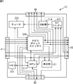
図5は、ディスプレイ11の内部構成例を示すブロック図である。
FIG. 5 is a block diagram illustrating an internal configuration example of the
MPU(Micro Processing Unit)311は、メモリ317に記憶されるプログラムを実行することにより、ディスプレイ11を構成する各部を制御する。また、MPU311は、左コネクタ部41乃至上コネクタ部44から供給される制御信号に従って処理を行い、制御信号を左コネクタ部41乃至上コネクタ部44に供給して外部に出力させる。
An MPU (Micro Processing Unit) 311 controls each part of the
RFスイッチャ313は、MPU311の制御に基づいて、外部から左コネクタ部41または下コネクタ部42に入力された放送用の高周波信号のいずれかを選択し、分配器314に供給する。分配器314は、RFスイッチャ313から供給された放送用の高周波信号を分配し、右コネクタ部43、上コネクタ部44、およびチューナ315に供給する。
Based on the control of the
チューナ315は、MPU311の制御に基づいてチャンネルを選択し、分配器314から提供された放送用の高周波信号から、選択されたチャンネルの放送用の高周波信号を抽出して映像信号および音声信号に変換し、クロスポイントスイッチャ316に供給する。
The
クロスポイントスイッチャ316は、MPU311の制御に従い、外部から左コネクタ部41に入力された映像信号および音声信号(左チャネルおよび右チャネルの音声信号)、または、外部から下コネクタ部42に入力された映像信号および音声信号のうちのいずれかを選択信号として選択し、その選択信号を、右コネクタ部43および上コネクタ部44から外部に出力させる。また、クロスポイントスイッチャ316は、MPU311の制御に従い、チューナ315から供給される映像信号および音声信号、または選択信号のうちのいずれかを選択し、表示部21に供給して、対応する映像(信号)を表示部21に表示させる。なお、音声信号は、図示せぬスピーカから出力される。
The
メモリ317は、MPU311が実行するプログラム、MPU311の動作に必要なデータを記憶する。
The
なお、RFスイッチャ313とクロスポイントスイッチャ316とは、MPU311の制御に従い、連動して信号を選択する。すなわち、クロスポイントスイッチャ316が、外部から左コネクタ部41に入力された映像信号および音声信号を選択信号として選択するとき、RFスイッチャ313は、外部から左コネクタ部41に入力された放送用の高周波信号を選択する。また、クロスポイントスイッチャ316が、外部から下コネクタ部42に入力された映像信号および音声信号を選択信号として選択するとき、RFスイッチャ313は、外部から下コネクタ部42に入力された放送用の高周波信号を選択する。
Note that the RF switcher 313 and the
また、MPU311が実行するプログラムは、メモリ317にあらかじめインストールしておくことができる。また、プログラムは、DVD(Digital Versatile Disc)等のリムーバブルな記憶媒体や、インターネット等のネットワークを介してディスプレイ11に供給し、メモリ317にインストールすることができる。
A program executed by the
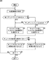
次に、図6のフローチャートを参照して、ディスプレイ11による信号選択処理について説明する。
Next, the signal selection processing by the
この信号選択処理は、ディスプレイ11の左コネクタ部41乃至上コネクタ部44の接続状態が変化した場合、或いは、必要に応じて、例えばユーザの指示によって、信号選択処理が要求された場合に開始することができる。
This signal selection process is started when the connection state of the
ステップS1において、MPU311は、図2に示したようなマルチディスプレイシステム101の各ディスプレイ11の配置を表す配置情報を、後述するように取得して、ステップS2に進む。
In step S1, the
ステップS2において、MPU311は、配置情報を基に左にディスプレイがあるか否か判定する。ステップS2において、左にディスプレイがあると判定された場合、すなわち、左コネクタ部41に他のディスプレイ(の右コネクタ)が接続される場合、ステップS3に進み、MPU311は、左にあるディスプレイから左コネクタ部41に入力される高周波信号を選択するように、RFスイッチャ313およびクロスポイントスイッチャ316を制御して、ステップS6に進む。
In step S2, the
これにより、左にあるディスプレイから左コネクタ部41に入力される映像信号および音声信号が、クロスポイントスイッチャ316を介して、右コネクタ部43および上コネクタ部44から出力されるとともに、左にあるディスプレイから左コネクタ部41に入力される高周波信号が、RFスイッチャ313および分配器314を介して、右コネクタ部43および上コネクタ部44から出力される。
Thereby, the video signal and the audio signal input to the
なお、ステップS2において、左にディスプレイがないと判定された場合であっても、例えば、左コネクタ部41にケーブルなどが接続され、外部から左コネクタ部41に映像信号等が入力されている場合には、MPU311は、ステップS2からステップS3に進み、クロスポイントスイッチャ316等に左コネクタ部41に入力されている映像信号等を選択させる。
Even when it is determined in step S2 that there is no display on the left, for example, when a cable or the like is connected to the
一方、ステップS2において、左にディスプレイがないと判定された場合、ステップS4に進み、MPU311は、配置情報を基に下にディスプレイがあるか否か判定する。
On the other hand, when it is determined in step S2 that there is no display on the left, the process proceeds to step S4, and the
ステップS4において、下にディスプレイがあると判定された場合、すなわち、下コネクタ部42に他のディスプレイ(の上コネクタ)が接続されている場合、ステップS5に進み、MPU311は、下にあるディスプレイから下コネクタ部42に入力される高周波信号を選択するように、RFスイッチャ313およびクロスポイントスイッチャ316を制御してステップS6に進む。
If it is determined in step S4 that there is a display below, that is, if another display (upper connector) is connected to the
これにより、下にあるディスプレイから下コネクタ部42に入力される映像信号および音声信号が、クロスポイントスイッチャ316を介して、右コネクタ部43および上コネクタ部44から出力されるとともに、下にあるディスプレイから下コネクタ部42に入力される高周波信号が、RFスイッチャ313および分配器314を介して、右コネクタ部43および上コネクタ部44から出力される。
As a result, the video signal and the audio signal input from the lower display to the
なお、ステップS4において、下にディスプレイがないと判定された場合であっても、例えば、下コネクタ部42にケーブルなどが接続され、外部から下コネクタ部42に映像信号等が入力されている場合には、MPU311は、ステップS4からステップS5に進み、クロスポイントスイッチャ316等に下コネクタ部42に入力されている映像信号等を選択させる。
Even if it is determined in step S4 that there is no display below, for example, a cable or the like is connected to the
一方、ステップS4において、下にディスプレイがないと判定された場合、すなわち、例えば、左コネクタ部41および下コネクタ部42のいずれにも、映像信号等が入力されていない場合、ステップS3に進み、MPU311は、左コネクタ部41側または下コネクタ部42側のうちの左コネクタ部41側を選択するように、RFスイッチャ313およびクロスポイントスイッチャ316を制御して、ステップS6に進む。
On the other hand, if it is determined in step S4 that there is no display below, that is, for example, if no video signal or the like is input to either the
ステップS6では、MPU311が、チューナ315が出力する映像(信号)を、表示部21に表示させるかどうかを判定する。
In step S <b> 6, the
ステップS6において、チューナ315が出力する映像(信号)を、表示部21に表示させると判定された場合、すなわち、例えば、ユーザが図示せぬリモートコマンダを操作することにより、ディスプレイ11のモードが、チューナ315が出力する映像を表示部21に表示させるモードとなっている場合、ステップS7に進み、MPU311は、クロスポイントスイッチャ316を制御することにより、チューナ315が出力する映像信号を、表示部21に出力させ、ステップS9に進む。
In step S6, when it is determined that the video (signal) output from the
これにより、表示部21では、チューナ315が出力する映像(信号)が表示される。
As a result, the video (signal) output from the
また、ステップS6において、チューナ315が出力する映像を、表示部21に表示させないと判定された場合、すなわち、ユーザがリモートコマンダを操作することにより、ディスプレイ11のモードが、外部から入力された映像(信号)を表示部21に表示させるモードとなっている場合、ステップS8に進み、MPU311は、クロスポイントスイッチャ316を制御することにより、ステップS3またはステップS5で右コネクタ部43と上コネクタ部44に出力した映像信号と同一の映像信号(選択信号)を、ディスプレイ11に出力させ、ステップS9に進む。
In step S6, when it is determined that the video output from the
これにより、表示部21では、ステップS3またはステップS5で右コネクタ部43と上コネクタ部44に出力された映像信号が表示される。
Thereby, on the
ステップS9では、MPU311が、信号選択処理を終了するかどうかを判定する。ステップS9において、信号選択処理を終了しないと判定された場合、ステップS1に戻り、以下、同様の処理が繰り返される。
In step S9, the
また、ステップS9において、信号選択処理を終了すると判定された場合、すなわち、例えば、ユーザが信号選択処理を行わないようにリモートコマンダを操作した場合、信号選択処理は終了する。 If it is determined in step S9 that the signal selection process is to be terminated, that is, for example, if the user operates the remote commander so as not to perform the signal selection process, the signal selection process is terminated.
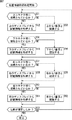
次に、図7のフローチャートを参照して、図6のステップS1で行われる配置情報を取得する配置情報取得処理について説明する。 Next, the arrangement information acquisition process for acquiring the arrangement information performed in step S1 of FIG. 6 will be described with reference to the flowchart of FIG.
ステップS51において、MPU311は、上コネクタ部44に他のディスプレイの下コネクタ部が接続されているか否か判定する。なお、MPU311は、ステップS51において、例えば、上コネクタ部44(の端子)にかかる電圧等に基づいて、上コネクタ部44に他のディスプレイの下コネクタ部が接続されているかどうかを判定する。後述するステップS54、ステップS57、およびステップS60でも同様である。
In step S <b> 51, the
ステップS51において、上コネクタ部44に他のディスプレイの下コネクタ部が接続されていると判定された場合、ステップS52に進み、MPU311は、上コネクタ部44に接続されている他のディスプレイである上のディスプレイから、配置情報を取得して、ステップS54に進む。
If it is determined in step S51 that the lower connector portion of another display is connected to the
ここで、配置情報が、例えば、上のディスプレイが上からN番目に配置されていることを表す場合、MPU311は、その配置情報に基づき、自身が上からN+1番目に配置されていることを認識して、その旨の配置情報を記憶する。
Here, when the arrangement information indicates, for example, that the upper display is arranged Nth from the top, the
一方、ステップS51において、上コネクタ部44に他のディスプレイの下コネクタ部が接続されていないと判定された場合、ステップS53に進み、MPU311は、ディスプレイ11が上から1番目に配置されていることを認識し、その旨の配置情報を記憶してステップS54に進む。
On the other hand, if it is determined in step S51 that the lower connector part of another display is not connected to the
ステップS54において、MPU311は、下コネクタ部42に他のディスプレイの上コネクタ部が接続されているか否か判定する。
In step S <b> 54, the
ステップS54において、下コネクタ部42に他のディスプレイの上コネクタ部が接続されていると判定された場合、ステップS55に進み、MPU311は、下コネクタ部42に接続されている他のディスプレイである下のディスプレイから、配置情報を取得して、ステップS57に進む。
If it is determined in step S54 that the upper connector portion of another display is connected to the
ここで、配置情報が、例えば、下のディスプレイが下からN番目に配置されていることを表す場合、MPU311は、その配置情報に基づき、自身が下からN+1番目に配置されていることを認識して、その旨の配置情報を記憶する。
Here, when the arrangement information indicates, for example, that the lower display is arranged Nth from the bottom, the
一方、ステップS54において、下コネクタ部42に他のディスプレイの上コネクタ部が接続されていないと判定された場合、ステップS56に進み、MPU311は、ディスプレイ11が下から1番目に配置されていることを認識し、その旨の配置情報を記憶してステップS57に進む。
On the other hand, if it is determined in step S54 that the upper connector part of another display is not connected to the
ステップS57において、MPU311は、右コネクタ部43に他のディスプレイの左コネクタ部が接続されているか否か判定する。
In step S <b> 57, the
ステップS57において、右コネクタ部43に他のディスプレイの左コネクタ部が接続されていると判定された場合、ステップS58に進み、MPU311は、右コネクタ部43に接続されている他のディスプレイである右のディスプレイから、配置情報を取得して、ステップS60に進む。
If it is determined in step S57 that the left connector portion of another display is connected to the
ここで、配置情報が、例えば、右のディスプレイが右からN番目に配置されていることを表す場合、MPU311は、その配置情報に基づき、自身が右からN+1番目に配置されていることを認識して、その旨の配置情報を記憶する。
Here, when the arrangement information indicates, for example, that the right display is arranged Nth from the right, the
一方、ステップS57において、右コネクタ部43に他のディスプレイの左コネクタ部が接続されていないと判定された場合、ステップS59に進み、MPU311は、ディスプレイ11が右から1番目に配置されていることを認識し、その旨の配置情報を記憶してステップS60に進む。
On the other hand, when it is determined in step S57 that the left connector portion of another display is not connected to the
ステップS60において、MPU311は、左コネクタ部41に他のディスプレイの右コネクタ部が接続されているか否か判定する。
In step S <b> 60, the
ステップS60において、左コネクタ部41に他のディスプレイの右コネクタ部が接続されていると判定された場合、ステップS61に進み、MPU311は、左コネクタ部41に接続されている他のディスプレイである左のディスプレイから、配置情報を取得して、ステップS63に進む。
If it is determined in step S60 that the right connector portion of another display is connected to the
ここで、配置情報が、例えば、左のディスプレイが左からN番目に配置されていることを表す場合、MPU311は、その配置情報に基づき、自身が左からN+1番目に配置されていることを認識して、その旨の配置情報を記憶する。
Here, when the arrangement information indicates, for example, that the left display is arranged Nth from the left, the
一方、ステップS60において、左コネクタ部41に他のディスプレイの右コネクタ部43が接続されていないと判定された場合、ステップS62に進み、MPU311は、ディスプレイ11が左から1番目に配置されていることを認識し、その旨の配置情報を記憶してステップS63に進む。
On the other hand, if it is determined in step S60 that the
ステップS63では、MPU311は、いままでに記憶した配置情報から、マルチディスプレイシステムを構成する各ディスプレイの配置位置を確定することができるかどうかを判定する。
In step S63, the
ステップS63において、マルチディスプレイシステムを構成する各ディスプレイの配置位置を、まだ確定することができないと判定された場合、ステップS51に戻り、以下、同様の処理が繰り返される。 If it is determined in step S63 that the arrangement position of each display constituting the multi-display system cannot be determined yet, the process returns to step S51, and the same processing is repeated thereafter.
また、ステップS63において、マルチディスプレイシステムを構成する各ディスプレイの配置位置を確定することができると判定された場合、リターンする。 If it is determined in step S63 that the arrangement position of each display constituting the multi-display system can be determined, the process returns.
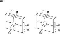
図8は、ディスプレイ11に対する、信号の入出力の様子を示している。
FIG. 8 shows how signals are input to and output from the
なお、図8、並びに後述する図9および図10では、説明を簡単にするために、映像信号にのみ注目して説明を行う。 In FIG. 8 and FIGS. 9 and 10 to be described later, only the video signal will be described for the sake of simplicity.
ディスプレイ11では、左コネクタ41に映像信号が入力される場合(左コネクタ部41の他、下コネクタ部42にも映像信号が入力される場合を含む)、図6で説明したことから、クロスポイントスイッチャ316は、図8の左の図に示すように、左コネクタ41に外部から入力された映像信号を選択し、右コネクタ43と上コネクタ44の両方から外部に出力する。
In the
また、ディスプレイ11では、下コネクタにのみ、映像信号が入力される場合、図6で説明したことから、クロスポイントスイッチャ316は、図8の右の図に示すように、下コネクタ42(図8では図示せず)に外部から入力された映像信号を選択し、右コネクタ43と上コネクタ44の両方から外部に出力する。
Further, in the
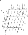
図9および図10は、複数のディスプレイ11で構成されるマルチディスプレイシステム101において映像信号が入力される経路を示している。
FIGS. 9 and 10 show paths through which video signals are input in the
なお、図9および図10では、マルチディスプレイシステム101の最も左下にあるディスプレイ111,1の左コネクタ部411,1(図9および図10において図示せず)に外部から映像信号が入力されている。
In FIGS. 9 and 10, a video signal is input from the outside to the left connector portion 41 1,1 (not shown in FIGS. 9 and 10) of the
図9は、9台のディスプレイ11を横×縦が3×3台になるように配置したマルチディスプレイシステム101における映像信号の経路を示している。
FIG. 9 shows a video signal path in the
図9において、ディスプレイ111,1は左コネクタ部411,1に外部から映像信号が入力されるため、その左コネクタ部411,1に入力される映像信号を、右コネクタ部431,1から右のディスプレイ111,2に出力するとともに、上コネクタ部441,1から上のディスプレイ112,1に出力する。
In FIG. 9, since a video signal is input from the outside to the
ディスプレイ112,1は、下のディスプレイ111,1のみから映像信号が入力されるため、その映像信号を、上のディスプレイ113,1と左のディスプレイ112,2に出力する。ディスプレイ113,1も、ディスプレイ112,1と同様に、下のディスプレイ113,1のみから映像信号が入力されるため、その映像信号を、上(上コネクタ部443,1)から出力するとともに、右(右コネクタ部433,1)からディスプレイ113,2に出力する。
Since the video signal is input only from the
ディスプレイ111,2,111,3,112,2,112,3,113,2、および113,3は、いずれも左から映像信号が入力されるため、その映像信号を、上と右に出力する。以上の結果、例えば、最も右上のディスプレイ113,3には、ディスプレイ111,1に入力された映像信号が、図9において太線で示すように、ディスプレイ111,1,112,1,113,1,および113,2を経由して供給される。
Since the
図9の、横×縦が3×3台のディスプレイ11で構成されるマルチディスプレイシステム101から、例えば、最上段の左から2番目のディスプレイ113,2を取り除くと、マルチディスプレイシステム101における映像信号の経路は、図10に示すようになる。
When, for example, the
ディスプレイ113,2を取り除くと、最も右上のディスプレイ113,3についてだけ、映像信号の入力の状態が変化する。
When the
すなわち、図9では、ディスプレイ113,3には、左から映像信号が入力されるが、図10では、ディスプレイ113,2がないので、ディスプレイ113,3には、下からのみ映像信号が入力される。このため、ディスプレイ113,3は、図10では、下に入力された映像信号を、上と右から出力する。
That is, in FIG. 9, the video signals are input to the
その結果、ディスプレイ113,3には、ディスプレイ111,1に入力された映像信号が、図10において太線で示すように、ディスプレイ111,1,112,1,112,2、および112,3を経由して供給される。
As a result, the video signals input to the
図6および図8で説明したように、ディスプレイ11は、左または下から入力される映像信号のうちの一方を選択し、すなわち、左と下の両方から映像信号が入力される場合には、左から入力される映像信号を選択し、下のみから映像信号が入力される場合には、その下から入力される映像信号を選択し、右と上から出力するので、マルチディスプレイシステム101において、ディスプレイ11の配置が変化しても、ユーザが、映像信号等の分配のために配線を繋ぎ変える必要がない。
As described with reference to FIGS. 6 and 8, the
なお、ディスプレイ11には、左コネクタ部41乃至上コネクタ部44のすべてを儲けるのではなく、左コネクタ部41と右コネクタ部43だけを設けることができる。ただし、この場合には、マルチディスプレイシステム101において縦方向に配置されるディスプレイ11同士は、ケーブルを用いて接続する必要がある。
Note that the
また、ディスプレイ11には、左コネクタ部41乃至上コネクタ部44のすべてを儲けるのではなく、下コネクタ部43と上コネクタ部44だけを設けることができる。ただし、この場合には、マルチディスプレイシステム101において横方向に配置されるディスプレイ11同士は、ケーブルを用いて接続する必要がある。
In addition, the
さらに、実施の形態では、ディスプレイ11の左と下に入力コネクタ部を設けるとともに、右と上に出力コネクタ部を設けるようにしたが、入力コネクタ部は、ディスプレイ11の右または上に設けてもよい。同様に、出力コネクタ部も左または下に設けてもよい。
Furthermore, in the embodiment, input connector portions are provided on the left and bottom of the
なお、本明細書において、フローチャートによって説明した各ステップは、必ずしも、記載された順序に沿って時系列的に行われる必要はなく、並列的あるいは個別に実行されてもよい。 In the present specification, the steps described by the flowcharts are not necessarily performed in time series in the order described, and may be performed in parallel or individually.
また、本明細書において、システムとは、複数の装置により構成される装置全体を表すものである。 Further, in this specification, the system represents the entire apparatus constituted by a plurality of apparatuses.
11 ディスプレイ,21 表示部,31 左側面,32 下側面,33 右側面,34 上側面,41 左コネクタ部,42 下コネクタ部,43 右コネクタ部,44 上コネクタ部,101 マルチディスプレイシステム,151 RF出力端子,152A乃至152C 映像出力端子,153A乃至153C 音声出力端子,154A乃至154C 音声出力端子,155 制御端子,161 RF入力端子,162A乃至162C 映像入力端子,163A乃至163C 音声入力端子,164A乃至164C 音声入力端子,165 制御端子,221 UWB送信アンテナ,231 UWB受信アンテナ,311 MPU,312 表示部,313 RFスイッチャ,314 分配器,315 チューナ,316 クロスポイントスイッチャ, 317 メモリ 11 Display, 21 Display, 31 Left Side, 32 Lower Side, 33 Right Side, 34 Upper Side, 41 Left Connector, 42 Lower Connector, 43 Right Connector, 44 Upper Connector, 101 Multi Display System, 151 RF Output terminal, 152A to 152C video output terminal, 153A to 153C audio output terminal, 154A to 154C audio output terminal, 155 control terminal, 161 RF input terminal, 162A to 162C video input terminal, 163A to 163C audio input terminal, 164A to 164C Audio input terminal, 165 control terminal, 221 UWB transmission antenna, 231 UWB reception antenna, 311 MPU, 312 display unit, 313 RF switcher, 314 distributor, 315 tuner, 316 crosspoint switcher, 3 7 memory
Claims (9)
前記表示手段が設けられた面に直交する前記筐体の4つの側面のうちの第1の側面に設けられた、外部から、少なくとも映像信号が入力される第1のコネクタ部と、
前記第1の側面と対向する第2の側面に設けられた、外部に、少なくとも映像信号を出力する第2のコネクタ部と
を備えるディスプレイ。 In a display having a rectangular parallelepiped housing in which display means for displaying an image is provided on one surface,
A first connector portion provided on the first side surface of the four side surfaces of the casing orthogonal to the surface on which the display means is provided, to which at least a video signal is input from the outside;
A display provided on the second side facing the first side, and having a second connector part for outputting at least a video signal to the outside.
前記ディスプレイの第2の側面に、他のディスプレイの第1の側面が対向するように、前記ディスプレイと前記他のディスプレイとが配置されたとき、前記ディスプレイの第2のコネクタ部と前記他のディスプレイの第1の側面に設けられた第1のコネクタ部とが電気的に接続される
請求項1に記載のディスプレイ。 When the display and the other display are arranged so that the first side surface of the display and the second side surface of the other display face each other, the first connector portion of the display and the other And a second connector portion provided on the second side surface of the display,
When the display and the other display are arranged so that the first side of the other display faces the second side of the display, the second connector portion of the display and the other display The display according to claim 1, wherein the first connector portion provided on the first side surface of the first connector portion is electrically connected.
前記第2のコネクタ部は、映像信号を無線で出力する
請求項1に記載のディスプレイ。 A video signal is input to the first connector portion wirelessly,
The display according to claim 1, wherein the second connector unit wirelessly outputs a video signal.
前記第2のコネクタ部からは、放送用の高周波信号、音声信号、または制御信号も出力される
請求項1に記載のディスプレイ。 The first connector portion also receives a high-frequency signal for broadcasting, an audio signal, or a control signal,
The display according to claim 1, wherein a high-frequency signal for broadcasting, an audio signal, or a control signal is also output from the second connector unit.
前記第3の側面と対向する第4の側面に設けられた、外部に、少なくとも、映像信号を出力する第4のコネクタ部と、
前記第1のコネクタ部または前記第3のコネクタ部に入力される映像信号のうちのいずれかを選択し、前記第2のコネクタ部および前記第4のコネクタ部から外部に出力させる選択手段と
をさらに備える請求項1に記載のディスプレイ。 A third connector portion provided on a third side surface other than the first and second side surfaces of the four side surfaces of the housing, to which at least a video signal is input from the outside;
A fourth connector portion that is provided on a fourth side surface facing the third side surface and outputs at least a video signal to the outside;
Selecting means for selecting one of the video signals input to the first connector section or the third connector section and outputting the selected video signal to the outside from the second connector section and the fourth connector section; The display according to claim 1, further comprising:
前記選択手段は、前記他のディスプレイが接続されているか否かの判定結果に応じて、前記第1または前記第3のコネクタ部に入力される映像信号のうちのいずれかを選択する
請求項5に記載のディスプレイ。 A determination means for determining whether or not another display is connected to the first or third connector portion;
The said selection means selects either of the video signals input into the said 1st or said 3rd connector part according to the determination result whether the said other display is connected. Display as described in.
前記表示手段が設けられた面に直交する前記筐体の4つの側面のうちの第1の側面に設けられた、外部から、少なくとも映像信号が入力される第1のコネクタ部と、
前記第1の側面と対向する第2の側面に設けられた、外部に、少なくとも映像信号を出力する第2のコネクタ部と、
前記筐体の4つの側面のうちの前記第1および前記第2の側面以外の第3の側面に設けられた、外部から、少なくとも映像信号が入力される第3のコネクタ部と、
前記第3の側面と対向する第4の側面に設けられた、外部に、少なくとも、映像信号を出力する第4のコネクタ部と
を備えるディスプレイの制御方法において、
前記第1または前記第3のコネクタ部に、他のディスプレイが接続されているか否かを判定し、
前記他のディスプレイが接続されているか否かの判定結果に応じて、前記第1または前記第3のコネクタ部に入力される映像信号のうちのいずれかを選択し、前記第2のコネクタ部および前記第4のコネクタ部から外部に出力させる
ステップを含むディスプレイの制御方法。 A rectangular parallelepiped housing in which display means for displaying an image is provided on one surface;
A first connector portion provided on the first side surface of the four side surfaces of the casing orthogonal to the surface on which the display means is provided, to which at least a video signal is input from the outside;
A second connector portion that is provided on the second side surface facing the first side surface and outputs at least a video signal to the outside;
A third connector portion provided on a third side surface other than the first and second side surfaces of the four side surfaces of the housing, to which at least a video signal is input from the outside;
In a display control method including at least a fourth connector portion that outputs a video signal, provided on a fourth side surface facing the third side surface,
Determining whether another display is connected to the first or third connector portion;
Depending on the determination result of whether or not the other display is connected, one of the video signals input to the first or third connector unit is selected, and the second connector unit and A display control method including a step of outputting to the outside from the fourth connector portion.
前記表示手段が設けられた面に直交する前記筐体の4つの側面のうちの第1の側面に設けられた、外部から、少なくとも映像信号が入力される第1のコネクタ部と、
前記第1の側面と対向する第2の側面に設けられた、外部に、少なくとも映像信号を出力する第2のコネクタ部と、
前記筐体の4つの側面のうちの前記第1および前記第2の側面以外の第3の側面に設けられた、外部から、少なくとも映像信号が入力される第3のコネクタ部と、
前記第3の側面と対向する第4の側面に設けられた、外部に、少なくとも、映像信号を出力する第4のコネクタ部とを備えるディスプレイを制御するコンピュータに実行させるプログラムにおいて、
前記第1または前記第3のコネクタ部に、他のディスプレイが接続されているか否かを判定し、
前記他のディスプレイが接続されているか否かの判定結果に応じて、前記第1または前記第3のコネクタ部に入力される映像信号のうちのいずれかを選択し、前記第2のコネクタ部および前記第4のコネクタ部から外部に出力させる
ステップを含むプログラム。 A rectangular parallelepiped housing in which display means for displaying an image is provided on one surface;
A first connector portion provided on the first side surface of the four side surfaces of the casing orthogonal to the surface on which the display means is provided, to which at least a video signal is input from the outside;
A second connector portion that is provided on the second side surface facing the first side surface and outputs at least a video signal to the outside;
A third connector portion provided on a third side surface other than the first and second side surfaces of the four side surfaces of the housing, to which at least a video signal is input from the outside;
In a program to be executed by a computer that controls a display provided on the fourth side facing the third side and provided with at least a fourth connector unit that outputs a video signal.
Determining whether another display is connected to the first or third connector portion;
Depending on the determination result of whether or not the other display is connected, one of the video signals input to the first or third connector unit is selected, and the second connector unit and A program comprising a step of outputting to the outside from the fourth connector section.
Priority Applications (1)
| Application Number | Priority Date | Filing Date | Title |
|---|---|---|---|
| JP2005361346A JP2007166364A (en) | 2005-12-15 | 2005-12-15 | Display, display control method, program, and recording medium |
Applications Claiming Priority (1)
| Application Number | Priority Date | Filing Date | Title |
|---|---|---|---|
| JP2005361346A JP2007166364A (en) | 2005-12-15 | 2005-12-15 | Display, display control method, program, and recording medium |
Publications (1)
| Publication Number | Publication Date |
|---|---|
| JP2007166364A true JP2007166364A (en) | 2007-06-28 |
Family
ID=38248730
Family Applications (1)
| Application Number | Title | Priority Date | Filing Date |
|---|---|---|---|
| JP2005361346A Pending JP2007166364A (en) | 2005-12-15 | 2005-12-15 | Display, display control method, program, and recording medium |
Country Status (1)
| Country | Link |
|---|---|
| JP (1) | JP2007166364A (en) |
Cited By (8)
| Publication number | Priority date | Publication date | Assignee | Title |
|---|---|---|---|---|
| JP2009271124A (en) * | 2008-04-30 | 2009-11-19 | Necディスプレイソリューションズ株式会社 | Display |
| WO2014115298A1 (en) * | 2013-01-25 | 2014-07-31 | Necディスプレイソリューションズ株式会社 | Monitor stand, display device, multi-monitor system and information writing method |
| WO2014132422A1 (en) * | 2013-02-28 | 2014-09-04 | Necディスプレイソリューションズ株式会社 | Image display device and automatic power supply control method |
| JP2017146423A (en) * | 2016-02-16 | 2017-08-24 | 学校法人東京工芸大学 | Display device |
| KR20190103738A (en) * | 2018-02-28 | 2019-09-05 | 삼성전자주식회사 | Display appartus |
| JP2021184079A (en) * | 2020-05-21 | 2021-12-02 | 緯創資通股▲ふん▼有限公司Wistron Corporation | Light emitting diode display system and module |
| CN116490819A (en) * | 2020-12-21 | 2023-07-25 | Sage电致变色显示有限公司 | Support system for electrochromic devices |
| US11972168B2 (en) | 2021-11-02 | 2024-04-30 | Samsung Electronics Co., Ltd. | Display device and controlling method thereof |
Citations (9)
| Publication number | Priority date | Publication date | Assignee | Title |
|---|---|---|---|---|
| JPH02273388A (en) * | 1989-04-13 | 1990-11-07 | Fuji Photo Film Co Ltd | Portable video tape recorder with television |
| JPH0832904A (en) * | 1994-07-20 | 1996-02-02 | Fujitsu General Ltd | Multi-panel display system |
| JPH11288252A (en) * | 1998-04-01 | 1999-10-19 | Daichu Denshi:Kk | Lighting device and extended display device using this device |
| JP2000242393A (en) * | 1999-02-23 | 2000-09-08 | Canon Inc | Information processing apparatus and control method thereof |
| JP2000276099A (en) * | 1999-03-23 | 2000-10-06 | Toshiba Corp | Multi-screen display device |
| JP2002006804A (en) * | 2000-06-27 | 2002-01-11 | Nec Corp | Multiple screen display device |
| JP2002176582A (en) * | 2000-12-06 | 2002-06-21 | Fuji Photo Film Co Ltd | Electronics |
| JP2004163706A (en) * | 2002-11-14 | 2004-06-10 | Hitachi Ltd | Display system control method for information processing equipment |
| JP2004205933A (en) * | 2002-12-26 | 2004-07-22 | Fuji Photo Film Co Ltd | Device and system for image display |
-
2005
- 2005-12-15 JP JP2005361346A patent/JP2007166364A/en active Pending
Patent Citations (9)
| Publication number | Priority date | Publication date | Assignee | Title |
|---|---|---|---|---|
| JPH02273388A (en) * | 1989-04-13 | 1990-11-07 | Fuji Photo Film Co Ltd | Portable video tape recorder with television |
| JPH0832904A (en) * | 1994-07-20 | 1996-02-02 | Fujitsu General Ltd | Multi-panel display system |
| JPH11288252A (en) * | 1998-04-01 | 1999-10-19 | Daichu Denshi:Kk | Lighting device and extended display device using this device |
| JP2000242393A (en) * | 1999-02-23 | 2000-09-08 | Canon Inc | Information processing apparatus and control method thereof |
| JP2000276099A (en) * | 1999-03-23 | 2000-10-06 | Toshiba Corp | Multi-screen display device |
| JP2002006804A (en) * | 2000-06-27 | 2002-01-11 | Nec Corp | Multiple screen display device |
| JP2002176582A (en) * | 2000-12-06 | 2002-06-21 | Fuji Photo Film Co Ltd | Electronics |
| JP2004163706A (en) * | 2002-11-14 | 2004-06-10 | Hitachi Ltd | Display system control method for information processing equipment |
| JP2004205933A (en) * | 2002-12-26 | 2004-07-22 | Fuji Photo Film Co Ltd | Device and system for image display |
Cited By (13)
| Publication number | Priority date | Publication date | Assignee | Title |
|---|---|---|---|---|
| JP2009271124A (en) * | 2008-04-30 | 2009-11-19 | Necディスプレイソリューションズ株式会社 | Display |
| WO2014115298A1 (en) * | 2013-01-25 | 2014-07-31 | Necディスプレイソリューションズ株式会社 | Monitor stand, display device, multi-monitor system and information writing method |
| JPWO2014115298A1 (en) * | 2013-01-25 | 2017-01-26 | Necディスプレイソリューションズ株式会社 | Monitor stand, display device, multi-monitor system, and information writing method |
| WO2014132422A1 (en) * | 2013-02-28 | 2014-09-04 | Necディスプレイソリューションズ株式会社 | Image display device and automatic power supply control method |
| JP7065418B2 (en) | 2016-02-16 | 2022-05-12 | 学校法人東京工芸大学 | Display device and array base |
| JP2017146423A (en) * | 2016-02-16 | 2017-08-24 | 学校法人東京工芸大学 | Display device |
| KR20190103738A (en) * | 2018-02-28 | 2019-09-05 | 삼성전자주식회사 | Display appartus |
| KR102464234B1 (en) | 2018-02-28 | 2022-11-07 | 삼성전자주식회사 | Display appartus |
| JP2021184079A (en) * | 2020-05-21 | 2021-12-02 | 緯創資通股▲ふん▼有限公司Wistron Corporation | Light emitting diode display system and module |
| JP7149316B2 (en) | 2020-05-21 | 2022-10-06 | 緯創資通股▲ふん▼有限公司 | Light emitting diode display system and module |
| US11210996B2 (en) | 2020-05-21 | 2021-12-28 | Wistron Corporation | Light-emitting diode display system and module |
| CN116490819A (en) * | 2020-12-21 | 2023-07-25 | Sage电致变色显示有限公司 | Support system for electrochromic devices |
| US11972168B2 (en) | 2021-11-02 | 2024-04-30 | Samsung Electronics Co., Ltd. | Display device and controlling method thereof |
Similar Documents
| Publication | Publication Date | Title |
|---|---|---|
| KR101920264B1 (en) | Display apparatus, control method thereof, and display system | |
| KR100953789B1 (en) | Signal processing apparatus, signal processing method, signal processing system, and computer readable recording medium | |
| US9134950B2 (en) | Video wall display system | |
| EP1326436B1 (en) | Displaying information | |
| US20080299912A1 (en) | Method and Structure in Support of the Formation of Substantially Co-Linear Wireless Device Pairings and Mitigation of Interference Effects in a Digital Multi-Media Communication Environment | |
| EP3819982B1 (en) | Image display device and video wall including the same | |
| JP2011257540A (en) | Multiple display system, image display method and display device | |
| EP2180696A2 (en) | Display device and radio transmission control method | |
| US10278300B2 (en) | Display device | |
| US10222826B2 (en) | Display device | |
| JP2007166364A (en) | Display, display control method, program, and recording medium | |
| JP2003067073A (en) | Information processing equipment | |
| JP2001160927A (en) | Tuner, monitor, video and audio playback device | |
| KR102909522B1 (en) | Control device and system including same | |
| US12055806B2 (en) | Display device | |
| US20090109092A1 (en) | Antenna apparatus | |
| JP2006080664A (en) | Signal reproducing apparatus and signal reproducing method | |
| JP5587866B2 (en) | Method and apparatus for display server with monitor function | |
| US20220394789A1 (en) | Image display apparatus and operation method therefor | |
| US11615768B2 (en) | Display apparatus, method of controlling the same, and display system | |
| KR101468122B1 (en) | System and Method For Controlling a Image Signal | |
| KR20130068149A (en) | Image processing apparatus and control method thereof | |
| KR20060030147A (en) | Signal transmission device of electronic device | |
| CN1980365A (en) | Signal transmission device of electronic instrument |
Legal Events
| Date | Code | Title | Description |
|---|---|---|---|
| A621 | Written request for application examination |
Free format text: JAPANESE INTERMEDIATE CODE: A621 Effective date: 20081204 |
|
| A131 | Notification of reasons for refusal |
Free format text: JAPANESE INTERMEDIATE CODE: A131 Effective date: 20100928 |
|
| A521 | Written amendment |
Free format text: JAPANESE INTERMEDIATE CODE: A523 Effective date: 20101027 |
|
| A131 | Notification of reasons for refusal |
Free format text: JAPANESE INTERMEDIATE CODE: A131 Effective date: 20101214 |
|
| A521 | Written amendment |
Free format text: JAPANESE INTERMEDIATE CODE: A523 Effective date: 20110127 |
|
| A131 | Notification of reasons for refusal |
Free format text: JAPANESE INTERMEDIATE CODE: A131 Effective date: 20110802 |
|
| A521 | Written amendment |
Free format text: JAPANESE INTERMEDIATE CODE: A523 Effective date: 20110901 |
|
| A02 | Decision of refusal |
Free format text: JAPANESE INTERMEDIATE CODE: A02 Effective date: 20120315 |