JP2007166328A - Optical add / drop adder, optical add / drop adder control method, and optical add / drop adder control program - Google Patents
Optical add / drop adder, optical add / drop adder control method, and optical add / drop adder control program Download PDFInfo
- Publication number
- JP2007166328A JP2007166328A JP2005361039A JP2005361039A JP2007166328A JP 2007166328 A JP2007166328 A JP 2007166328A JP 2005361039 A JP2005361039 A JP 2005361039A JP 2005361039 A JP2005361039 A JP 2005361039A JP 2007166328 A JP2007166328 A JP 2007166328A
- Authority
- JP
- Japan
- Prior art keywords
- optical
- control
- light
- optical power
- state
- Prior art date
- Legal status (The legal status is an assumption and is not a legal conclusion. Google has not performed a legal analysis and makes no representation as to the accuracy of the status listed.)
- Granted
Links
Images

Classifications
-
- H—ELECTRICITY
- H04—ELECTRIC COMMUNICATION TECHNIQUE
- H04J—MULTIPLEX COMMUNICATION
- H04J14/00—Optical multiplex systems
- H04J14/02—Wavelength-division multiplex systems
- H04J14/0201—Add-and-drop multiplexing
- H04J14/0202—Arrangements therefor
- H04J14/0209—Multi-stage arrangements, e.g. by cascading multiplexers or demultiplexers
-
- H—ELECTRICITY
- H04—ELECTRIC COMMUNICATION TECHNIQUE
- H04J—MULTIPLEX COMMUNICATION
- H04J14/00—Optical multiplex systems
- H04J14/02—Wavelength-division multiplex systems
- H04J14/0201—Add-and-drop multiplexing
- H04J14/0202—Arrangements therefor
- H04J14/021—Reconfigurable arrangements, e.g. reconfigurable optical add/drop multiplexers [ROADM] or tunable optical add/drop multiplexers [TOADM]
- H04J14/0212—Reconfigurable arrangements, e.g. reconfigurable optical add/drop multiplexers [ROADM] or tunable optical add/drop multiplexers [TOADM] using optical switches or wavelength selective switches [WSS]
-
- H—ELECTRICITY
- H04—ELECTRIC COMMUNICATION TECHNIQUE
- H04J—MULTIPLEX COMMUNICATION
- H04J14/00—Optical multiplex systems
- H04J14/02—Wavelength-division multiplex systems
- H04J14/0221—Power control, e.g. to keep the total optical power constant
- H04J14/02216—Power control, e.g. to keep the total optical power constant by gain equalization
Landscapes
- Engineering & Computer Science (AREA)
- Computer Networks & Wireless Communication (AREA)
- Signal Processing (AREA)
- Optical Communication System (AREA)
Abstract
【課題】光分岐挿入装置において、追加部品によるコスト上昇を招くことなく、ASEノイズの累積等に起因する波長挿入時のデータ障害を確実に防止する。
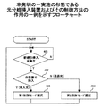
【解決手段】波長多重光に対する信号光の挿入/分岐を行う光分岐挿入装置において、新規な挿入光の追加時に(ステップ401)、自装置で信号光を挿入したか否かを判別し(ステップ402)、自装置で追加した信号光のチャネルについては第1制御モードで光パワーの一定制御を実行し(ステップ403)、自装置を通過する信号光のチャネルについては第2制御モードで光パワーの一定制御を実行する。第1制御モードでは、光パワーの値にて光パワーの自動制御に遷移し、第2制御モードでは、第1制御モードで動作する側からの挿入光の運用開始情報に基づいて光パワーの自動制御に遷移するため、通過光の制御でASEノイズに起因して光パワーが目標レベルを大きく逸脱して隣接チャネルを乱すことが防止される。
【選択図】図1In an optical add / drop multiplexer, data failure at the time of wavelength insertion due to accumulation of ASE noise or the like is surely prevented without causing an increase in cost due to additional components.
In an optical add / drop multiplexer that inserts / drops signal light with respect to wavelength multiplexed light, when adding new insert light (step 401), it is determined whether or not signal light is inserted by itself (step 401). 402) For the signal light channel added by the own apparatus, constant optical power control is executed in the first control mode (step 403), and for the signal light channel passing through the own apparatus, the optical power is obtained in the second control mode. The constant control is executed. In the first control mode, the optical power is automatically controlled based on the value of the optical power. In the second control mode, the optical power is automatically controlled based on the operation start information of the inserted light from the side operating in the first control mode. Since the transition is made to the control, it is possible to prevent the optical power from greatly deviating from the target level and disturbing the adjacent channel due to the ASE noise in the control of the passing light.
[Selection] Figure 1
Description
本発明は、光分岐挿入技術および制御プログラムに関し、たとえば、波長分離多重(WDM:Wavelength Division Multiplex)を用いた光ネットワークを構成する光分岐挿入装置およびその制御技術等に適用して有効な技術に関する。 The present invention relates to an optical add / drop technique and a control program, for example, an optical add / drop apparatus that constitutes an optical network using wavelength division multiplexing (WDM) and a technique that is effective when applied to a control technique thereof. .
近年、通信容量と通信距離の増大にともない、ネットワークの大容量化と長距離化が要求されている。この要求を満たすために、従来、基幹ネットワークでは、波長分離多重を用いた光ネットワークが利用されている。 In recent years, with an increase in communication capacity and communication distance, there has been a demand for an increase in network capacity and distance. In order to satisfy this requirement, an optical network using wavelength demultiplexing has been conventionally used in the backbone network.
波長分離多重を用いた光ネットワークでは、都市間の通信要求に対して、任意経路に任意波長を挿入し、任意経路から任意波長の信号光を分岐して受信する光分岐挿入装置(OADM:Optical Add and Drop Multiplexer)が用いられる。 In an optical network using wavelength division multiplexing, in response to a communication request between cities, an optical add / drop multiplexer (OADM) that inserts an arbitrary wavelength into an arbitrary path and branches and receives signal light of an arbitrary wavelength from the arbitrary path. Add and Drop Multiplexer) is used.
WDMでは、通常、複数の信号光の波長を包含する波長範囲を纏めて増幅するEDFA等の光増幅が用いられるが、この光増幅では、ASEノイズ(ASE:Amplified Spontaneous Emission)が発生するため、複数のOADMを多段に接続して使用する場合、ASEノイズの累積に起因する障害に対する対策が必要となる。 In WDM, optical amplification such as EDFA that amplifies a wavelength range including a plurality of signal light wavelengths is generally used. However, in this optical amplification, ASE noise (ASE: Amplified Spontaneous Emission) occurs. When using a plurality of OADMs connected in multiple stages, it is necessary to take measures against failures caused by accumulation of ASE noise.
たとえば、特許文献1には、OADMにおける光分波器と光合波器の間における個々の信号光の光路上に、個々の信号光に同調した光フィルタを配置することで、信号光以外のASEノイズを除去しようとする技術が開示されている。
For example, in
また、当該特許文献1には、合波器の出力側の光路上に、個々の信号光毎の光パワーを検出する光モニタを配置し、観測された光パワーの情報を、光フィルタ制御部に帰還することで、個々の信号光のレベルを最大にしようとする技術も開示されている。
In
特許文献2には、OADMにおける光分波器と光合波器とでフリースペクトルレンジを異なるものを使用することで、ASEノイズの累積的な増加を防止しようとする技術が開示されている。
しかし、上述の特許文献1および特許文献2のいずれにおいても、以下のような、光挿入(ADD)時における技術的課題は認識されていない。
すなわち、WDMでは、ある周波数間隔で設定された複数の波長の信号光の各々の強度(光パワー)を、目標レベルに揃えるように制御する必要があり、新たに信号光を挿入する場合には、挿入された信号光を目標レベルに誘導する制御が必要となる。
However, neither of
That is, in the WDM, it is necessary to control the intensity (optical power) of each of the signal lights having a plurality of wavelengths set at a certain frequency interval so as to match the target level. Therefore, control for guiding the inserted signal light to the target level is required.
このため、挿入光が第1閾値レベルに到達するまで待機状態を維持し、この第1閾値レベルを超過したら信号レベルの自動制御状態に移行し、この自動制御状態において信号レベルが第2閾値レベル(>第1閾値レベル)よりも低下した場合には待機状態に移行する、という制御を個々のOADMにおいて行わせることが考えられる。 Therefore, the standby state is maintained until the insertion light reaches the first threshold level, and when the first threshold level is exceeded, the state shifts to the automatic control state of the signal level, and the signal level is set to the second threshold level in the automatic control state. It is conceivable that individual OADMs are controlled to shift to a standby state when the value falls below (> first threshold level).
通常、自動制御状態における目標レベルへの制御は、個々の信号光の光路に設けられた光減衰器の開度を調節することで行われる。
しかし、ASEノイズは、波長多重光のほぼ全範囲の信号レベルを全体的に増加させるようにシフトさせるため、多段に接続された複数のOADMを通過する間に累積され、挿入対象の未使用の波長域の信号レベルも増加しており、上述の第1閾値レベルを超過している可能性がある。
Usually, the control to the target level in the automatic control state is performed by adjusting the opening of the optical attenuator provided in the optical path of each signal light.
However, since the ASE noise is shifted so as to increase the signal level of almost the entire range of the wavelength multiplexed light as a whole, it is accumulated while passing through a plurality of OADMs connected in multiple stages, and the unused insertion target is inserted. The signal level in the wavelength band is also increasing and may exceed the first threshold level described above.
このため、多段に接続された複数のOADMにおいて上述の待機状態と自動制御状態との間の遷移制御を信号レベルの検出に基づいて行った場合には、光信号を挿入するOADMの後段に位置し、当該光信号を通過させるOADMでは、到来する挿入波長域の信号光のレベルがASEノイズによって第1閾値レベルを超過していた場合、自動制御状態に遷移した状態となる。 Therefore, when the transition control between the standby state and the automatic control state described above is performed based on the detection of the signal level in a plurality of OADMs connected in multiple stages, the OADMs are positioned at the subsequent stage of the OADM into which the optical signal is inserted. However, in the OADM that allows the optical signal to pass, when the level of the incoming signal light in the insertion wavelength region exceeds the first threshold level due to ASE noise, the OADM enters the automatic control state.
また、この時のASEノイズのレベルは、目標レベルよりも低いため、自動制御状態の制御系では、目標レベルに到達させるために、減衰器の開度を最大にして待つ状態となる。 Further, since the level of the ASE noise at this time is lower than the target level, the control system in the automatic control state waits with the opening of the attenuator being maximized in order to reach the target level.
そして、この自動制御状態にあるOADMに、前段側のOADMで光ファイバの接続による光挿入を実行すると、減衰器の開度が最大となっているため、通過側のOADMにおける挿入光の信号レベルは、目標レベルを突き抜けて異常に突出し、隣接する波長の他の信号光の信号レベルを乱して、混信(クロストーク)等のデータエラーをひき起こす、という技術的課題がある。 When optical insertion is performed by connecting an optical fiber to the OADM in the automatic control state using the OADM on the front stage side, the opening level of the attenuator is maximized. Has a technical problem that it protrudes abnormally through the target level, disturbs the signal level of other signal lights of adjacent wavelengths, and causes data errors such as crosstalk.
この技術的課題を回避するためには、OADMの接続段数を制限して、ASEノイズの累積を回避することが考えられるが、OADMを用いた通信システムの構築や通信距離に制約を生じる、という別の技術的課題を生じる。
本発明の目的は、複数の光分岐挿入装置を含む光通信システムにおいて、追加部品によるコスト上昇を招くことなく、ASEノイズ等に起因する波長挿入時のデータ障害を確実に防止することが可能な技術を提供することにある。 An object of the present invention is to reliably prevent a data failure at the time of wavelength insertion due to ASE noise or the like without causing an increase in cost due to additional components in an optical communication system including a plurality of optical add / drop multiplexers. To provide technology.
本発明の他の目的は、複数の光分岐挿入装置を含む光通信システムにおいて、光分岐挿入装置の接続段数に制約を生じることなく、任意数の光分岐挿入装置の多段接続による長距離通信を実現することが可能な技術を提供することにある。 Another object of the present invention is an optical communication system including a plurality of optical add / drop multiplexers, which performs long-distance communication by multi-stage connection of an arbitrary number of optical add / drop multiplexers without limiting the number of connection stages of the optical add / drop multiplexers. It is to provide a technology that can be realized.
本発明の他の目的は、複数の光分岐挿入装置を含む光通信システムにおいて、光増幅器にて発生するASEノイズの多段累積を波長単位に除去することが可能な技術を提供することにある。 Another object of the present invention is to provide a technique capable of removing multi-stage accumulation of ASE noise generated in an optical amplifier in units of wavelengths in an optical communication system including a plurality of optical add / drop multiplexers.
本発明の第1の観点は、波長多重光に対する光分岐挿入を行う光スイッチ手段と、前記波長多重光に含まれる個々の信号光単位に光パワーの制御を行う光パワー制御手段と、他の装置との間で制御情報の送受信を行う制御情報通信手段と、を含む光分岐挿入装置であって、
前記光パワー制御手段は、
前記光パワーの自動制御への遷移および離脱が、前記光パワーと閾値とを比較することによって行われる第1制御モードと、
前記光パワーの自動制御への遷移が前記制御情報通信手段を介して他の前記光分岐挿入装置から通知される制御情報に基づいて実行され、前記自動制御からの離脱が前記光パワーと閾値との比較に基づいて実行される第2制御モードと、
を実現する制御論理を含む光分岐挿入装置を提供する。
According to a first aspect of the present invention, there is provided an optical switch means for performing optical add / drop insertion on wavelength multiplexed light, an optical power control means for controlling optical power for each signal light unit included in the wavelength multiplexed light, An optical add / drop device including control information communication means for transmitting / receiving control information to / from the device,
The optical power control means includes
A first control mode in which the transition to and removal from the automatic control of the optical power is performed by comparing the optical power with a threshold;
Transition to automatic control of the optical power is executed based on control information notified from the other optical add / drop multiplexer via the control information communication means, and the departure from the automatic control is the optical power and threshold value. A second control mode executed based on the comparison of
An optical add / drop device including a control logic for realizing the above is provided.
本発明の第2の観点は、波長多重光に対する信号光の光分岐挿入を行う光分岐挿入装置の制御方法であって、
制御対象の前記信号光が、自装置において挿入された挿入光か、外部から到来する通過光かを判別するステップと、
前記信号光が前記挿入光の場合には、前記挿入光の光パワーの自動制御への遷移および離脱が、前記光パワーと閾値とを比較することによって行われる第1制御モードを実行し、
前記信号光が前記通過光の場合には、前記通過光の光パワーの自動制御への遷移が、他の前記光分岐挿入装置から通知される制御情報に基づいて実行され、前記自動制御からの離脱が、前記光パワーと閾値との比較に基づいて行われる第2制御モードを実行するステップと、
を含む光分岐挿入装置の制御方法を提供する。
A second aspect of the present invention is a method of controlling an optical add / drop device for performing optical add / drop of signal light with respect to wavelength multiplexed light,
Determining whether the signal light to be controlled is insertion light inserted in the device itself or passing light coming from outside;
When the signal light is the insertion light, a transition to and a withdrawal from the automatic control of the optical power of the insertion light is performed by comparing the optical power with a threshold value, and a first control mode is executed.
When the signal light is the passing light, the transition to the automatic control of the optical power of the passing light is executed based on the control information notified from the other optical add / drop device, and from the automatic control, Executing a second control mode in which detachment is performed based on a comparison between the optical power and a threshold;
A method of controlling an optical add / drop multiplexer including the above is provided.
本発明の第3の観点は、波長多重光に対する信号光の光分岐挿入を行う光分岐挿入装置の制御プログラムであって、
前記光分岐挿入装置を構成するコンピュータに、
制御対象の前記信号光が、自装置において挿入された挿入光か、外部から到来する通過光かを判別する機能と、
前記信号光の光パワーの自動制御への遷移および離脱が、前記光パワーと閾値とを比較することによって行われる第1制御モードを実行する機能と、
前記信号光の光パワーの自動制御への遷移が、他の前記光分岐挿入装置から通知される制御情報に基づいて実行され、前記自動制御からの離脱が、前記光パワーと閾値との比較に基づいて行われる第2制御モードを実行する機能と、
を実現させる光分岐挿入装置の制御プログラムを提供する。
A third aspect of the present invention is a control program for an optical add / drop device for performing optical add / drop of signal light with respect to wavelength multiplexed light,
In the computer constituting the optical add / drop device,
A function of discriminating whether the signal light to be controlled is inserted light inserted in the device itself or transmitted light coming from the outside;
A function of executing a first control mode in which transition to and removal from the optical power of the signal light are performed by comparing the optical power with a threshold;
The transition to the automatic control of the optical power of the signal light is executed based on the control information notified from the other optical add / drop device, and the departure from the automatic control is a comparison between the optical power and the threshold value. A function of executing a second control mode performed based on the
A control program for an optical add / drop multiplexer that realizes the above is provided.
上記した本発明によれば、たとえば、光分岐挿入装置において、自装置が挿入した挿入光の波長ルート(Add Path)では、光パワーに応じてフィードバック制御による自動制御状態に移行することが可能であり、実際の挿入光の運用開始に応じてフィードバック制御に自動的に移行して出力パワーの一定制御を行う第1制御モードに設定する。 According to the present invention described above, for example, in the optical add / drop multiplexer, in the wavelength route (Add Path) of the inserted light inserted by itself, it is possible to shift to an automatic control state by feedback control according to the optical power. Yes, the first control mode is set to perform the constant control of the output power by automatically shifting to the feedback control according to the actual operation of the inserted light.
一方、後段の他の光分岐挿入装置においては、他の光分岐挿入装置から到来する通過光の波長ルート(Through Path)では、当該通過光の波長域の偽の光パワー(すなわちASEノイズの累積)に影響されないシャットダウン状態で待機し、前段の挿入装置から通知された光挿入の有無を示す制御情報に基づいて、真に挿入光の運用が開始された場合(挿入光の波長が有効の場合)のみシャットダウン状態から、フィードバック制御による出力パワーの一定制御を行う状態に遷移する第2制御モードが設定される。 On the other hand, in the other optical add / drop device in the subsequent stage, in the wavelength route (Through Path) of the passing light arriving from the other optical add / drop device, the false optical power (that is, the accumulation of ASE noise) in the wavelength range of the passing light. ) Waiting in a shutdown state that is not affected by the), and the operation of the inserted light is truly started based on the control information indicating the presence / absence of the optical insertion notified from the previous insertion device (when the wavelength of the inserted light is valid) ) Only, the second control mode is set to transit from the shutdown state to a state in which constant control of output power by feedback control is performed.
これにより、信号光の挿入元の光分岐挿入装置の下流側の他の光分岐挿入装置では、制御情報を介して、実際に通過光(上流側の光分岐挿入装置における挿入光)の運用が開始されたことを通知されるまでは、当該通過光の波長域の光パワーの自動制御は行われないために、当該波長域におけるASEノイズの累積的な発生が抑止される。 Thereby, in the other optical add / drop devices downstream of the optical signal add / drop device from which the signal light is inserted, the operation of the passing light (the inserted light in the upstream optical add / drop device) is actually performed via the control information. Until the start is notified, the automatic control of the optical power in the wavelength range of the passing light is not performed, so that the cumulative generation of ASE noise in the wavelength range is suppressed.
換言すれば、複数の光分岐挿入装置間におけるASEノイズの累積を、信号光の波長域単位に除去することができる。
このため、通過光の波長域におけるASEノイズの累積による誤った出力パワーの検出によって自動的にフィードバック制御へ遷移することを阻止できる。
In other words, the accumulation of ASE noise among a plurality of optical add / drop multiplexers can be removed in units of wavelength range of signal light.
For this reason, it is possible to prevent the automatic transition to the feedback control by detecting the erroneous output power due to the accumulation of ASE noise in the wavelength range of the passing light.
この結果、フィードバック制御の状態で待機中に、他の装置から通過光が到来して、当該通過光の光パワーが目標レベルを突き抜けた状態となり、隣接する波長域の他の信号光を乱す等のデータ障害の発生を確実に回避することが可能となる。 As a result, while waiting in the feedback control state, passing light comes from another device, and the optical power of the passing light passes through the target level, disturbing other signal light in the adjacent wavelength range, etc. It is possible to reliably avoid the occurrence of data failure.
換言すれば、ASEノイズの累積に影響されることなく、任意の段数の光分岐挿入装置を接続して光通信システムを構築でき、容易に長距離通信を実現できる。
第1および第2制御モードは、ソフトウェアやファームウェアで実現されるため、既存のシステムを変更することなく、追加部品等を必要とせずに低コストでASEノイズ対策を実現できる。
In other words, an optical communication system can be constructed by connecting any number of stages of optical add / drop multiplexers without being affected by the accumulation of ASE noise, and long distance communication can be easily realized.
Since the first and second control modes are realized by software or firmware, it is possible to realize ASE noise countermeasures at a low cost without changing an existing system and without requiring additional components.
本発明によれば、複数の光分岐挿入装置を含む光通信システムにおいて、追加部品によるコスト上昇を招くことなく、ASEノイズ等に起因する波長挿入時のデータ障害を確実に防止することができる。 According to the present invention, in an optical communication system including a plurality of optical add / drop multiplexers, it is possible to reliably prevent data failure at the time of wavelength insertion due to ASE noise or the like without causing an increase in cost due to additional components.
また、複数の光分岐挿入装置を含む光通信システムにおいて、光分岐挿入装置の接続段数に制約を生じることなく、任意数の光分岐挿入装置の多段接続による長距離通信を実現することができる。 Further, in an optical communication system including a plurality of optical add / drop multiplexers, it is possible to realize long-distance communication by multistage connection of an arbitrary number of optical add / drop multiplexers without limiting the number of connection stages of the optical add / drop multiplexers.
また、複数の光分岐挿入装置を含む光通信システムにおいて、光増幅器にて発生するASEノイズの多段累積を波長単位に除去することができる。
また、複数の光分岐挿入装置を含む光通信システムにおいて、光増幅器にて発生するASEノイズの多段累積を波長単位に除去することができる。
Also, in an optical communication system including a plurality of optical add / drop multiplexers, multistage accumulation of ASE noise generated in an optical amplifier can be removed in units of wavelengths.
Also, in an optical communication system including a plurality of optical add / drop multiplexers, multistage accumulation of ASE noise generated in an optical amplifier can be removed in units of wavelengths.
以下、図面を参照しながら、本発明の実施の形態について詳細に説明する。
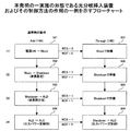
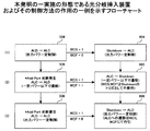
図1は、本実施の形態の光分岐挿入装置およびその制御方法の作用の一例を示すフローチャートである。
Hereinafter, embodiments of the present invention will be described in detail with reference to the drawings.
FIG. 1 is a flowchart showing an example of the operation of the optical add / drop multiplexer and its control method of the present embodiment.
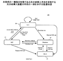
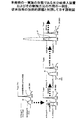
図2Aおよび図2Bは、本発明の一実施の形態である光分岐挿入方法を実施する光分岐挿入装置の作用の一例を示す状態遷移図である。
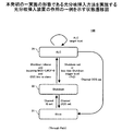
図3は、本発明の一実施の形態である光分岐挿入装置の構成の一例を示す概念図である。
2A and 2B are state transition diagrams showing an example of the operation of the optical add / drop multiplexer that performs the optical add / drop method according to the embodiment of the present invention.
FIG. 3 is a conceptual diagram showing an example of the configuration of an optical add / drop multiplexer according to an embodiment of the present invention.
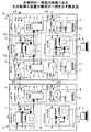
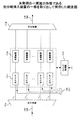
図4は、本実施の形態の光分岐挿入装置の一部を取り出して例示した概念図である。
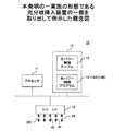
図5は、本実施の形態の光分岐挿入装置の一部を取り出して例示した概念図である。
図6は、本実施の形態の光分岐挿入装置にて用いられる情報テーブルの一例を示す概念図である。
FIG. 4 is a conceptual diagram illustrating a part of the optical add / drop multiplexer of this embodiment.
FIG. 5 is a conceptual diagram illustrating a part of the optical add / drop multiplexer of this embodiment.
FIG. 6 is a conceptual diagram showing an example of an information table used in the optical add / drop multiplexer of this embodiment.
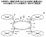
図7は、本実施の形態の光分岐挿入装置を含むWDM通信システムの構成の一例を示す概念図である。
図8および図9は、本実施の形態の光分岐挿入装置およびその制御方法の作用の一例を示すフローチャートである。
図10は、本実施の形態の光分岐挿入装置およびその制御方法の作用の一例を示す説明図である。
FIG. 7 is a conceptual diagram showing an example of the configuration of a WDM communication system including the optical add / drop multiplexer of this embodiment.
8 and 9 are flowcharts illustrating an example of the operation of the optical add / drop multiplexer and the control method thereof according to the present embodiment.
FIG. 10 is an explanatory diagram showing an example of the operation of the optical add / drop multiplexer and the control method thereof according to the present embodiment.
図7に例示されるように、本実施の形態のWDM通信システム300は、光伝送路301、光伝送路302、ネットワーク中継機器303、光分岐挿入装置100を含んでいる。
As illustrated in FIG. 7, the
光伝送路301および光伝送路302は互いに逆方向に波長多重光30を伝送する光ファイバ等の光媒体で構成されている。
この光伝送路301および光伝送路302の経路中には、複数の光分岐挿入装置100が設けられており、波長多重光30に対する信号光31の挿入(追加)/分岐を行うことで、複数のネットワーク中継機器303の間における波長多重光30を介した情報通信を実現する。
The
In the
図3を参照して本実施の形態の光分岐挿入装置100の構成例について説明する。
本実施の形態の光分岐挿入装置100は、伝送方向が逆な一対の光伝送路301、光伝送路302に接続され、これらの各々を伝送される波長多重光30からの信号光31の取り出し、および波長多重光30への信号光31の挿入を行う。
A configuration example of the optical add /
The optical add /
光伝送路301および光伝送路302の各々に対する処理は、伝送方向が逆なだけで互いに等価なので、以下では、光伝送路301に連なる構成を中心に説明を進める。
本実施の形態の光分岐挿入装置100は、波長挿入ユニット110、波長挿入ユニット120、アンプユニット130、アンプユニット140、光管理ユニット150、光管理ユニット160、波長分岐ユニット170、波長分岐ユニット180、制御基板190を含んでいる。
Since the processing for each of the
The optical add /
光伝送路301から到来する波長多重光30は、アンプユニット130、波長挿入ユニット110、アンプユニット140を通過する。
光伝送路302から到来する波長多重光30は、アンプユニット140、波長挿入ユニット120、アンプユニット130を通過する。
The wavelength multiplexed light 30 coming from the
The wavelength multiplexed light 30 coming from the
波長挿入ユニット110は、波長挿入/通過部111、光パワーモニタ部112、光パワー制御部113、挿入ポート114、通過入力ポート115、通過出力ポート116を含んでいる。
The
波長挿入/通過部111は、通過する波長多重光30に対して、必要に応じて挿入ポート114から信号光31の挿入を行う。
光パワーモニタ部112は、たとえば、スペクトラムアナライザで構成され、波長挿入/通過部111から出力される波長多重光30に含まれる個々の信号光31の光パワーを計測して、光パワー信号40として光パワー制御部113に入力する。
The wavelength inserting / passing
The optical
光パワー制御部113は、光パワー信号40に基づいて、光減衰制御信号41を波長挿入/通過部111に入力することにより、波長挿入/通過部111を制御する。
図4に例示されるように、波長挿入/通過部111は、光分波器111a、光合波器111b、光スイッチ111c、光減衰器111d、スイッチ制御部111fを含んでいる。
The optical
As illustrated in FIG. 4, the wavelength inserting / passing
光分波器111aは、通過入力ポート115の波長多重光30から、波長の異なる複数の信号光31を異なる光路に分岐させる。以下では、必要に応じて、個々の波長(信号光31)に対応した通信路をチャネルと呼ぶ。
The
光合波器111bは、波長の異なる複数の信号光31を一つの波長多重光30に多重化し、通過出力ポート116に出力する。
光分波器111aと光合波器111bとの間における個々の信号光31の光路上には、光スイッチ111c、光減衰器111dが配置されている。
The optical multiplexer 111 b multiplexes a plurality of
An
光スイッチ111cは、対応するチャネルに対して、挿入ポート114に入力される信号光31の挿入を行う。
光減衰器111dは、通過する信号光31の光路を全開から全閉の間で変化させることで、信号光31の光パワー(光量)を制御する。
The
The
スイッチ制御部111fは外部からの指示に基づいて、光スイッチ111c、光減衰器111dを制御する。
本実施の形態の場合には、たとえば、光パワー制御部113から入力される光減衰制御信号41に基づいて、個々の光減衰器111dにおける信号光31の減衰量を制御する。
The
In the case of the present embodiment, for example, the attenuation amount of the
本実施の形態の光パワー制御部113は、一例として、図5に例示されるようなコンピュータ10で構成されている。
コンピュータ10は、プロセッサ11、メモリ12、入出力インタフェース13を含んでいる。
The optical
The
プロセッサ11は、たとえばDSP等からなり、メモリ12に格納されたプログラムを実行することで、後述のような各種の制御を行う。
メモリ12は、プロセッサ11が実行する光パワー制御プログラム14、さらには、光パワー制御テーブル15を保持している。
The
The
光パワー制御プログラム14は、プロセッサ11によって実行されることにより、個々のチャネル毎に、後述の第1制御モード14A、第2制御モード14Bを実現する。
入出力インタフェース13は、コンピュータ10(光パワー制御部113)と外部との間における情報の入出力を制御する。
The optical
The input /
本実施の形態の場合には、光パワー信号40、光減衰制御信号41、波長状態通知信号42、チャネル制御信号201、等の入出力が行われる。
波長状態通知信号42は、他の光分岐挿入装置100の光パワー制御部113から、光管理ユニット150を介して受け取る情報であり、波長設定信号WCS、波長状態情報WCF、等の情報を含む。
In the case of the present embodiment, input / output of an
The wavelength
任意の信号光31を挿入する波長挿入ユニット110の光パワー制御部113は、挿入される当該信号光31に関する波長状態通知信号42(波長設定信号WCS、波長状態情報WCF)を、光管理ユニット160を介して、光伝送路301の下流側の光分岐挿入装置100の波長挿入ユニット110(光パワー制御部113)に伝達する。
The optical
他の光分岐挿入装置100で挿入された信号光31が通過する光分岐挿入装置100の波長挿入ユニット110(光パワー制御部113)では、光管理ユニット150を介して、当該信号光31を挿入した上流側の光分岐挿入装置100の波長挿入ユニット110(光パワー制御部113)から伝達される波長状態通知信号42に基づいて、後述のような光パワーの制御を行う。
In the wavelength inserting unit 110 (optical power control unit 113) of the optical add /
チャネル制御信号201は、制御基板190を介して外部の制御端末200から、個々の光分岐挿入装置100に対して与えられる、信号光31の挿入、通過、分岐、等の指令情報、シャットダウン状態の設定変更の指令情報を含む。
The
図6に例示されるように、本実施の形態の光パワー制御テーブル15は、チャネル名15a、チャネル属性15b、制御ステータス15c、波長設定情報15d、チャネル状態15e、シャットダウン制御情報15f、等の情報が、個々のチャネル名15a毎に設定可能になっている。
As illustrated in FIG. 6, the optical power control table 15 of the present embodiment includes information such as a
チャネル名15aは、複数の信号光31の波長に対応したチャネルに付与された識別名である。
チャネル属性15bは、個々のチャネル名15aで特定される信号光31について、当該信号光31が自装置で挿入するものか、他の光分岐挿入装置100で挿入され、自装置を通過する(自装置で分岐される)ものかを識別するための情報が設定される。
The
The
すなわち、当該信号光31が自装置で挿入された場合には“A”(Add)が設定され、自装置を通過する場合には“T”(Through)が設定される。
そして、このチャネル属性15bの設定状態に応じて、当該チャネルにおいて第1制御モード14A、第2制御モード14Bのいずれで動作するかを決定する。
That is, “A” (Add) is set when the
Then, according to the setting state of the
属性の異なる複数のチャネルが混在する場合は、コンピュータ10は、マルチタスクで光パワー制御プログラム14を実行することで、個々のチャネル毎に第1制御モード14Aと第2制御モード14Bを並行して実行する。
When a plurality of channels having different attributes coexist, the
波長設定情報15dは、当該チャネル名15aで特定される信号光31が、運用中(Channel In service(IS))か、運用停止中(Channel Out Of service(OOS))か、を識別するために設定される。
The
運用中(Channel IS)は、波長設定信号WCS=1に対応し、運用停止中(Channel OOS)は、波長設定信号WCS=0に対応する。
チャネル状態15eは、運用中(波長設定信号WCS=1)の信号光31について、何らかの原因で障害が発生しているか否かを示す情報が設定される。
In operation (Channel IS) corresponds to the wavelength setting signal WCS = 1, and in operation (Channel OOS) corresponds to the wavelength setting signal WCS = 0.
In the
すなわち、当該チャネル(信号光31)に障害有りの場合は、波長状態情報WCF=1が設定され、障害無しの場合には、波長状態情報WCF=0が設定される。
シャットダウン制御情報15fは、後述のシャットダウン状態22への遷移/解除の状態を指示する情報が設定される。
That is, when there is a failure in the channel (signal light 31), wavelength state information WCF = 1 is set, and when there is no failure, wavelength state information WCF = 0 is set.
The
このシャットダウン制御情報15fの設定は、制御端末200がチャネル制御信号201を介して行うこともできるし、上流側の光分岐挿入装置100から制御信号光162を介して行うこともできる。
The setting of the
光パワー制御部113(コンピュータ10)は、この光パワー制御テーブル15に設定された情報に基づいて、個々のチャネルにおける光パワーの制御を行う。
波長挿入ユニット120は、波長挿入/通過部121、光パワーモニタ部122、光パワー制御部123、挿入ポート124、通過入力ポート125、通過出力ポート126を含んでいる。
The optical power control unit 113 (computer 10) controls the optical power in each channel based on information set in the optical power control table 15.
The
波長挿入ユニット120の各部の構成は、上述の波長挿入ユニット110と同様であるので、説明は割愛する。
アンプユニット130は、プリアンプ部131、光分岐カプラ132、光分岐カプラ133、ポストアンプ部134、光合流カプラ135を含んでいる。
Since the structure of each part of the
The
プリアンプ部131は、たとえば、EDFA等の光増幅器で構成され、光伝送路301から波長挿入ユニット110に入力される波長多重光30を光のままで増幅する。
光分岐カプラ132は、プリアンプ部131に入力される波長多重光30に含まれる制御信号光162を分岐させて光管理ユニット150に導く。
The
The optical branching
光分岐カプラ133は、プリアンプ部131から波長挿入/通過部111に至る波長多重光30の一部を分岐させ、波長分岐ユニット170に導く。
ポストアンプ部134は、たとえば、EDFA等の光増幅器で構成され、波長挿入/通過部121から到来する波長多重光30を光のままで増幅して光伝送路302に出力する。
The optical branching
The
光合流カプラ135は、光管理ユニット150から出力される制御信号光152を、ポストアンプ部134から出力される波長多重光30に合波して多重化する。
アンプユニット140は、プリアンプ部141、光分岐カプラ142、光分岐カプラ143、ポストアンプ部144、光合流カプラ145を含んでいる。
The optical combining
The
プリアンプ部141は、たとえば、EDFA等の光増幅器で構成され、光伝送路302から波長挿入ユニット120に入力される波長多重光30を光のままで増幅する。
光分岐カプラ142は、プリアンプ部141に入力される波長多重光30に含まれる制御信号光152を分岐させて光管理ユニット160に導く。
The
The optical branching
光分岐カプラ143は、プリアンプ部141から波長挿入/通過部121に至る波長多重光30の一部を分岐させ、波長分岐ユニット180に導く。
ポストアンプ部144は、たとえば、EDFA等の光増幅器で構成され、波長挿入/通過部111から到来する波長多重光30を光のままで増幅して光伝送路301に出力する。
The optical branching
The
光合流カプラ145は、光管理ユニット160から出力される制御信号光162を、ポストアンプ部144から出力される波長多重光30に合波して多重化する。
光管理ユニット150は、制御部151を含んでいる。この制御部151は、光伝送路302を介して、制御信号光152を隣接する光分岐挿入装置100に設けられた光管理ユニット160に送信することで、たとえば、上述の波長状態通知信号42等の情報を送る。
The optical combining
The
また、制御部151は、光伝送路301を介して後述の光管理ユニット160から到来する制御信号光162によって光管理ユニット160から上述の波長状態通知信号42等の情報を受信する。
Further, the
光管理ユニット160は、制御部161を含んでいる。この制御部161は、光伝送路301を介して、制御信号光162を隣接する光分岐挿入装置100に設けられた光管理ユニット160に送信することで、上述の波長状態通知信号42等の情報を送る。
The
また、制御部161は、光伝送路302を介して上述の光管理ユニット150から到来する制御信号光152によって当該光管理ユニット150から上述の波長状態通知信号42等の情報を受信する。
Further, the
波長分岐ユニット170は、波長ドロップ部171、ドロップポート172を含んでいる。波長ドロップ部171は、光分岐カプラ133で分岐された波長多重光30から任意の波長の信号光31を取り出してドロップポート172の一つに出力する。
The
同様に、波長分岐ユニット180は、波長ドロップ部181、ドロップポート182を含んでいる。波長ドロップ部181は、光分岐カプラ143で分岐された波長多重光30から任意の波長の信号光31を取り出してドロップポート182の一つに出力する。
Similarly, the
制御基板190は、外部の制御端末200から、光分岐挿入装置100を構成する上述の各ユニットを制御する制御通信インタフェースを提供する。
制御端末200は、たとえばパーソナルコンピュータ等で構成され、チャネル制御信号201を、光分岐挿入装置100の波長挿入ユニット110および波長挿入ユニット120に入力することで、信号光31の挿入、追加、分岐取り出し、等の設定を行う。
The
The
以下、本実施の形態の光分岐挿入方法および光分岐挿入装置100の作用の一例について説明する。
本実施の形態では、個々の光分岐挿入装置100では、波長多重光30に多重化して運用する個々の信号光31(波長:チャネル)毎に、自装置が当該信号光31を挿入するのか、他の上流側の光分岐挿入装置100で波長多重光30に挿入された信号光31が通過するのか、に応じて、当該信号光31の光パワー信号の制御方法が異なる。
Hereinafter, an example of the operation of the optical add / drop method and the optical add /
In the present embodiment, each optical add /
すなわち、図1のフローチャートに例示されるように、個々の光分岐挿入装置100は、制御端末200から、波長多重光30の波長範囲のうちの空き波長域を使用した、新たな信号光31の運用開始の指示を待つ(ステップ401)。
That is, as illustrated in the flowchart of FIG. 1, each optical add /
そして、運用開始の指示があった場合には、自装置における信号光31の挿入が指示されたか否かを判別する(ステップ402)。
そして、自装置における信号光31の挿入が指示された場合には、図2Aに例示される第1制御モード14Aを選択し(ステップ403)、光パワー制御テーブル15の対応するチャネル名15aのチャネル属性15bとして“A”を設定する。以下、この信号光31の挿入を行う光分岐挿入装置100を、必要に応じて挿入装置と記す。
Then, if there is an instruction to start operation, it is determined whether or not the insertion of the
When the insertion of the
同じ信号光31に関して、挿入装置以外の当該信号光31が通過する他の光分岐挿入装置100(以下、必要に応じて通過装置と記す)は、自装置に接続された制御端末200、または、挿入装置からの制御信号光162(波長状態通知信号42)を介した情報通知により、自装置の光パワー制御テーブル15におけるチャネル属性15bに“T”を設定する。
Other optical add / drop devices 100 (hereinafter referred to as passing devices as needed) through which the
また、光パワーの制御方法として図2Bに例示される第2制御モード14Bを選択する(ステップ404)。
こうして、波長多重光30に含まれる複数の信号光31の各々については、一つの挿入装置(光分岐挿入装置100)と、それ以外の通過装置(光分岐挿入装置100)が決定され、個々の光分岐挿入装置100では、光パワー制御テーブル15のチャネル属性15bに対応した属性が設定される。
Further, the
Thus, for each of the plurality of
図3の光伝送路301のルートの例では、ある信号光31について、動作説明上、装置Aを光挿入した波長ルート(Add Path)の挿入装置、装置Bを光スルーした波長ルート(Through Path)の通過装置として説明する。
In the example of the route of the
上述のように、本実施の形態の場合には、挿入装置と通過装置とで光パワーの制御方法は異なる。
まず、装置Aでは、波長挿入/通過部111の挿入ポート114に信号光31(WDM信号)を挿入する。
As described above, in the case of the present embodiment, the optical power control method differs between the insertion device and the passage device.
First, in the device A, the signal light 31 (WDM signal) is inserted into the
波長挿入/通過部111は、光パワー制御テーブル15の波長設定情報15d(波長設定信号WCS)に従い、挿入ポート114の各々から挿入される入力波長を選択し、通過入力ポート115から到来する他の信号光31との波長多重を行い波長多重光30として通過出力ポート116から後段のポストアンプ部144に出力する。この波長多重光30の一部は、光パワーモニタ部112に入力される。
The wavelength inserting / passing
ポストアンプ部144は、通過出力ポート116から到来する波長多重光30に対して伝送距離(伝送ロス)分の光増幅を行い、光伝送路301を介して装置Bのプリアンプ部131へ出力する。
The
光管理ユニット160は、光パワー制御部113から得た波長状態通知信号42に含まれる、波長設定信号WCS、波長状態情報WCFを、制御信号光162を介して後段の装置Bの光管理ユニット150および光パワー制御部113に通知する。
The
装置Bのプリアンプ部131は到来する波長多重光30に対して装置Aとの間の光伝送路301の伝送距離(伝送ロス)分の光増幅を行い、波長挿入/通過部111の通過入力ポート115に出力する。
The
装置Bの波長挿入/通過部111は、制御信号光162、光管理ユニット150、波長状態通知信号42を介して、装置Aの側から通知された波長設定信号WCS、波長状態情報WCFに従い、通過入力ポート115から到来する波長多重光30と個々の挿入ポート114から挿入される入力波長(信号光31)を選択し、波長多重を行い、通過出力ポート116を介して後段のポストアンプ部144に出力する。
The wavelength inserting / passing
通過出力ポート116に出力される波長多重光30の一部は、光パワーモニタ部112に入力される。
ここで、波長多重光30に含まれる複数の信号光31は、各々の光パワー信号を所定のターゲットレベルTLに揃える必要がある。その理由は、個々の信号光31の光パワーのレベルがばらつくと、クロストーク等の好ましくない現象が発生するからである。
A part of the wavelength multiplexed light 30 output to the
Here, it is necessary for the plurality of
そこで、本実施の形態の場合、個々の波長挿入ユニット110では、光パワー制御部113(この場合、コンピュータ10の光パワー制御プログラム14)が、光パワーモニタ部112で検出された個々の信号光31の光パワー信号40に基づいて、波長挿入/通過部111の内部の個々の光減衰器111dの開度を制御することで、波長多重光30に含まれる複数の信号光31の光パワーをターゲットレベルTLに揃える光パワー制御を行う。
Therefore, in the case of the present embodiment, in each
この信号光31の光パワー制御において、本実施の形態の場合では、挿入(パス)装置の場合と、通過(パス)装置の場合とで、上述のように異なる制御を行う。
すなわち、ある信号光31を装置Aで挿入し、当該信号光31が装置Bを通過する場合、当該信号光31に関しては、装置Aでは第1制御モード14Aが実行され、装置Bでは、第2制御モード14Bを実行する。
In the optical power control of the
That is, when a certain signal light 31 is inserted by the device A and the signal light 31 passes through the device B, the device A executes the
信号光31を光挿入する波長ルート(Add Path)の場合は、光パワー制御プログラム14は、図2Aの第1制御モード14Aを実行する。
まず、光分岐挿入装置100の電源投入時の初期はブロック状態21と定義し、入力波長選択および光パワー制御を行わない状態である。
In the case of the wavelength route (Add Path) into which the
First, the initial state when the optical add /
次に、制御端末200を介してユーザから設定される波長設定信号WCSの設定(WCS=1:Channel In service)に従い、入力波長選択を実施している間、シャットダウン状態22とする。
Next, according to the setting of the wavelength setting signal WCS set by the user via the control terminal 200 (WCS = 1: Channel In service), the
入力波長選択が完了した後、制御端末200からの指示(Shutdown Release)により、シャットダウン状態22からオートレベルダウン状態23(ALD:Auto Level Down)へ遷移する。
After the input wavelength selection is completed, a transition from the
このオートレベルダウン状態23は、光減衰器111dを半開きにさせた状態であり、当該信号光31の入力パワーがある一定以上レベル(ALD Release Level)(第1閾値Th1)あるとオートレベルコントロール状態24(ALC:Auto Level Control)に遷移する。
The auto level down
そして、このオートレベルコントロール状態24では、光パワー制御部113が、光パワーモニタ部112から得られる光パワー信号40に基づくフィードバック制御により、個々の波長域の信号光31が期待するターゲットレベルTLになるよう更に光減衰器111dを徐々に開く制御を行う。
In the auto
もし、光減衰器111dを更に開ききっても、ターゲットレベルTLに達しない場合、ある一定以下レベル(第2閾値Th2)(ALD Trigger Level)であると判断し、オートレベルダウン状態23に遷移させ待機させる。
If the target level TL is not reached even if the
この光減衰器111dの半開き状態は、光減衰器111dの後方(通過出力ポート116側)にて光パワーモニタ部112により信号光31のモニタを行っているため、光入力の有無を判断するために必須となる。
In the half-open state of the
尚、ユーザから制御端末200を介して強制的にシャットダウン状態22への遷移指示(Shutdown set)が設定された場合、シャットダウン状態22で待機し、波長設定信号WCS=0(Channel OOS)が設定された場合は、ブロック状態21で待機する。
When the user has forcibly set the
通過する波長ルート(Through Path)の場合には、光パワー制御プログラム14は、図2Bに例示される第2制御モード14Bを実行する。
まず、電源立上げ時の初期はブロック状態21と定義し、入力波長選択および光パワー制御部113による光パワー制御を行わない状態である。
In the case of a passing wavelength route (Through Path), the optical
First, the initial state when the power is turned on is defined as a
次にユーザからの波長設定信号WCS=1の設定による波長有効化(Channel IS)の情報に従い、入力波長選択を実施している間、シャットダウン状態22とする。
入力波長選択が完了した後、制御端末200からのシャットダウン解放指示(Shutdown Release)を設定する。そして、光管理ユニット150の制御部151を介して、挿入元の装置から通知された波長設定信号WCSの状態(Channel IS/OOS)と、波長状態情報WCFの状態(Wave Channel Fail / Non Fail)に従い、オートレベルコントロール状態24への遷移の可否を判定する。
Next, according to the information of wavelength validation (Channel IS) by setting the wavelength setting signal WCS = 1 from the user, the
After the input wavelength selection is completed, a shutdown release instruction (Shutdown Release) from the
すなわち、波長設定信号WCS=1(In service状態)であり、かつ、波長状態情報WCF=0(Non Fail)の場合に限って、シャットダウン状態22からオートレベルコントロール状態24(ALC:Auto Level Control)に遷移する。
That is, only when the wavelength setting signal WCS = 1 (In service state) and the wavelength state information WCF = 0 (Non Fail), from the
そして、このオートレベルコントロール状態24では、光パワー制御部113が、光パワーモニタ部112から得られる光パワー信号40に基づくフィードバック制御により、個々の波長域の信号光31が期待するターゲットレベルTLになるように光減衰器111dを徐々に開く制御を行う。
In the auto
もし、光減衰器111dを更に開ききっても、ターゲットレベルTLに達しない場合には、ある一定以下レベル(第3閾値Th3)(Shutdown Trigger Level)であると判断し、シャットダウン状態22に遷移させ待機させる。
If the target level TL is not reached even if the
なお、ユーザ(制御端末200)から強制的にシャットダウン状態22への遷移(Shutdown set)が設定された場合、シャットダウン状態22で待機し、波長設定信号WCS=0(Channel OOS)が設定された場合は、ブロック状態21に遷移して待機する。
When the user (control terminal 200) forcibly transitions to the shutdown state 22 (Shutdown set), waits in the
このように、本実施の形態の場合には、自装置で信号光31を挿入した波長ルート(Add Path)では、第1制御モード14Aにより、光減衰器111dを半開き状態にさせ、光パワー制御部113が光パワー信号40のフィードバック制御を行いつつ出力パワーの一定制御を行う。
As described above, in the case of the present embodiment, in the wavelength route (Add Path) in which the
一方、ASEノイズが累積する信号光31の通過波長ルート(Through Path)では、第2制御モード14Bにより、シャットダウン状態22で待機し、前段の挿入装置からの制御信号光162を介した波長設定信号WCS、波長状態情報WCF等の波長状態通知信号42に基づいて、通過する信号光31の波長が真に有効の場合のみ、シャットダウン状態22からオートレベルコントロール状態24に遷移して、光パワー制御部113が、光パワー信号40を用いたフィードバック制御を行いつつ通過光の出力パワーの一定制御を行う。
On the other hand, in the passing wavelength route (Through Path) of the
このため、ASEノイズの累積による誤った偽波長による出力パワーの一定制御を確実に回避させることが可能である。
また、運用中に制御信号光162等の制御回線に異常をきたしても、シャットダウン状態22への遷移自体は、信号光31の光レベルによる遷移であるため、既存の運用回線に対して動作仕様変更等の影響を与えることなく、光分岐挿入装置100間にて確実にASEノイズの影響を排除することで、複数の光分岐挿入装置100を含むWDM通信システム300における長距離伝送が実現できる。
For this reason, it is possible to reliably avoid constant control of the output power due to an erroneous false wavelength due to accumulation of ASE noise.
Further, even if an abnormality occurs in the control line such as the
また、第1制御モード14A、第2制御モード14Bは、ソフトウェアやファームウェアで実現できるため、光分岐挿入装置100に対する新たな部品追加等によるコストアップを生じることもない。
Further, since the
このことを、図10を参照して説明する。従来の光分岐挿入装置では、信号光31が挿入光か通過光かに関係なく、図2Aの第1制御モード14Aの制御を行っていた。
信号波形30Aのように挿入装置(パス)では、挿入開始時には、挿入対象の信号光31(チャネルCH39)が未入力の状態でも、挿入開始時の光信号レベルの引き込みに備えてオートレベルコントロール状態24への遷移を第1閾値Th1(ALDrelease level)で判定する。
This will be described with reference to FIG. In the conventional optical add / drop device, the control in the
In the insertion device (path) as in the
このため、ASEノイズ32が当該第1閾値Th1を超過すると、信号波形30Bのように、オートレベルコントロール状態24に遷移して光パワー制御部113は、光減衰器111dを全開にする制御が行われる。
For this reason, when the
この波長多重光30に含まれるASEノイズ32は次のノードの光分岐挿入装置100にそのまま伝播し、第1閾値Th1を超えているので、当該光分岐挿入装置100でも、信号波形30Cに示されるようにオートレベルコントロール状態24に遷移して光減衰器111dを全開にする。
Since the
この状態が後段に位置する光分岐挿入装置100で繰り返されると、信号波形30Dのように、使用開始前のチャネル(CH39)におけるASEノイズ32が累積されてターゲットレベルTLと同等になる。
When this state is repeated in the optical add /
そして、このような状態において、信号光31の挿入元の光分岐挿入装置100において、実際に当該信号光31をチャネル(CH39)に挿入すると、下流の通過装置側では、オートレベルコントロール状態24で光減衰器111dを全開にしているため、挿入された信号光31は、減衰されることなく、たとえば信号波形30Dのように、ターゲットレベルTLを突き抜けた異常に大きな信号レベルとなる。
In such a state, in the optical add /
この結果、このチャネル(CH39)の異常に大きな信号レベルに影響されて、隣接する運用中のチャネル(CH40)の信号光31が乱されて、伝送障害となることが懸念される。
As a result, there is a concern that the
これに対して、本実施の形態の場合には、信号光31の挿入を行う挿入装置では第1制御モード14Aの制御を行うが、それ以外の通過装置の側では、第2制御モード14Bで動作するため、挿入装置からの波長設定信号WCS=1、波長状態情報WCF=0、等の通知受けなければ、光減衰器111dを開くオートレベルコントロール状態24には遷移しない。
On the other hand, in the case of the present embodiment, the insertion device that inserts the
このため、挿入開始時に、挿入装置において第1制御モード14Aにより、オートレベルコントロール状態24に遷移したとしても、下流側の他の通過装置では、シャットダウン状態22のままであるため、挿入対象のチャネルの光減衰器111dは閉じており、ASEノイズ32が通過装置側に累積して伝播することが防止される。
For this reason, even when the insertion device transitions to the auto
そして、挿入装置では、実際に信号光31をチャネルに挿入した後に、波長設定信号WCS、波長状態情報WCFの情報を、制御信号光162を介して通過装置側に通知してオートレベルコントロール状態24に遷移させる。
In the insertion device, after the
これにより、挿入装置で挿入された信号光31は、通過装置においては、第2制御モード14Bによる光パワー制御部113によるフィードバック制御により、光減衰器111dを徐々に開くことで、目的のターゲットレベルTLに徐々に移行して安定化するように制御される。
As a result, the
このため、挿入された信号光31がターゲットレベルTLを突き抜けて異常に大きくなり、隣接するチャネルの信号光31を乱してクロストーク等の通信障害を招くことを確実に防止できる。
For this reason, it can be reliably prevented that the inserted
上述の本実施の形態の光分岐挿入装置100の動作を、図8および図9を参照して、より具体的に説明する。
光挿入した挿入装置の波長ルート(Add Path)と、次段以降の通過装置での光スルーした波長ルート(Through Path)の動作を、通常時の動作と、異常発生時の動作に分けて説明する。
The operation of the above described optical add /
The operation of the wavelength route (Add Path) of the optical insertion device and the wavelength route (Through Path) of the optical passage through the passing device in the subsequent stages are divided into normal operation and operation when an abnormality occurs. To do.
なお、説明の簡略化のため通過装置は既に運用状態待ち(電源立上げから波長設定完了状態)であることを前提に説明する。
図8に例示されるように、通常時の動作では、挿入装置は、電源投入によりブロック状態21(初期状態)に遷移するとともに、通過装置に対してWCS=0,WCF=0を通知する(ステップ501)。
In order to simplify the description, the description will be made on the assumption that the passing device is already waiting for an operation state (wavelength setting completion state after power-on).
As illustrated in FIG. 8, in the normal operation, the insertion device transitions to the block state 21 (initial state) when the power is turned on, and notifies the passing device of WCS = 0 and WCF = 0 ( Step 501).
このとき、通過装置は、ブロック状態21で待機する(ステップ601)。
次に、挿入装置では、制御端末200から光パワー制御テーブル15の波長設定情報15dに波長設定信号WCS=1を設定する操作(波長設定)により、ブロック状態21からシャットダウン状態22に遷移する。また、通過装置に対してWCS=1,WCF=1を通知する(ステップ502)。
At this time, the passing device waits in the block state 21 (step 601).
Next, in the insertion apparatus, the
この時、通過装置は、WCS=1が通知されたことにより、ブロック状態21からシャットダウン状態22に遷移する(ステップ602)。
次に、挿入装置では、制御端末200からシャットダウン制御情報15fに“release”を設定することで、シャットダウン状態22からオートレベルダウン状態23に遷移し(波長設定完了)、通過装置に対してWCS=1,WCF=1、シャットダウン状態22の“release”を通知する(ステップ503)。
At this time, the passing device transits from the
Next, the insertion device sets “release” in the
この時、通過装置では、まだ波長状態情報WCF=0でないため、シャットダウン状態22のままで待機する(ステップ603)。
次に、挿入装置は、挿入ポート114から入力される信号光31の光パワー信号40を監視する。そして、所定の第1閾値Th1(ALDreleaseTh)を超過した時点で、オートレベルダウン状態23からオートレベルコントロール状態24に遷移し、挿入ポート114から挿入された信号光31の出力パワーをターゲットレベルTLに一致させる出力パワー一定制御を開始する。同時に通過装置に対してWCS=1,WCF=0を通知する(ステップ504)。
At this time, since the wavelength state information WCF is not 0 yet, the passing device waits in the shutdown state 22 (step 603).
Next, the insertion device monitors the
これを受けた通過装置の側の光パワー制御部113では、シャットダウン制御情報15f=“release”、WCS=1、WCF=0の条件が揃ったので、シャットダウン状態22からオートレベルコントロール状態24に遷移する。
In response to this, the optical
そして、光パワーモニタ部112からの光パワー信号40に基づくフィードバック制御により、挿入装置側から到来する通過光(信号光31)の出力パワーをターゲットレベルTLに一致させる出力パワー一定制御を実行する(ステップ604)。
Then, by feedback control based on the
なお、この通過装置側では、信号光31(通過光)の光パワー信号40が、所定の第3閾値Th3(この実施の形態では第2閾値Th2と同一)を下回った時点、あるいは、制御端末200からシャットダウン制御情報15fに“set”が設定された時点で、オートレベルコントロール状態24からシャットダウン状態22に遷移する。
At the passing device side, when the
このような通常の稼働状態で、たとえば、信号光31(挿入光)の途絶等の異常が発生した場合は、図9に示されるように、以下のような動作を行う。
すなわち、上述のステップ504のように、挿入装置は、オートレベルダウン状態23からオートレベルコントロール状態24に遷移して信号光31(挿入光)の出力パワー一定制御を実行するとともに、通過装置に対してWCS=1,WCF=0を通知する。
In such a normal operation state, for example, when an abnormality such as interruption of the signal light 31 (inserted light) occurs, the following operation is performed as shown in FIG.
That is, as in
これにより、上述のステップ603のように、通過装置では、シャットダウン状態22からオートレベルコントロール状態24に遷移して出力パワー一定制御を実行する。
この状態で、挿入装置において挿入ポート114で信号光31(挿入光)の光断発生が発生すると、当該挿入装置では、光パワー信号40が第2閾値Th2より下回った時点でオートレベルコントロール状態24からオートレベルダウン状態23に遷移するとともに、通過装置に対してWCS=1,WCF=1を通知する(ステップ505)。
As a result, as in
In this state, when an optical interruption of the signal light 31 (insertion light) occurs at the
この時、通過装置の側では、信号光31(通過光)が第3閾値Th3を下回ったことを検出した時点で、オートレベルコントロール状態24からシャットダウン状態22に遷移する。このシャットダウン状態22では光減衰器111dは閉じられており、ASEノイズの伝播は遮断された状態となる(ステップ605)。
At this time, on the passing device side, when it is detected that the signal light 31 (passing light) has fallen below the third threshold Th3, the state shifts from the auto
このように、通過装置(第2制御モード14B)では、オートレベルコントロール状態24からシャットダウン状態22への遷移は、通過光の光パワー(光パワー信号40)の低下に基づいて自動的に行われ、WCS,WCFの情報はシャットダウン状態22への遷移のトリガとしては使用しない。
As described above, in the passing device (
その後、挿入装置の側で、挿入ポート114における信号光31(挿入光)の光断が復旧すると、第1閾値Th1と光パワー信号40との比較により、オートレベルダウン状態23からオートレベルコントロール状態24に自動的に遷移して出力パワー一定制御を行うとともに、通過装置に対してWCS=1,WCF=0を通知する(ステップ506)。
Thereafter, when the interruption of the signal light 31 (insertion light) at the
これを受けた通過装置では、挿入装置から通知されたWCS=1,WCF=0の条件に基づいて、シャットダウン状態22からオートレベルコントロール状態24に遷移して、信号光31(通過光)の出力パワー一定制御を再開する(ステップ606)。
In response to this, the passing device transitions from the
このように、通過装置におけるオートレベルコントロール状態24への遷移は、挿入装置から通知されたWCS,WCFの情報に基づいて行われ、光パワーが一定以下であればシャットダウン状態22のまま待機することになる。
As described above, the transition to the auto
このように、本実施の形態によれば、図8のフローチャートに例示されるような挿入光の運用開始時はもとより、図9に例示されるような運用中の光障害の発生および回復時においても、第1制御モード14Aで動作する挿入(パス)装置以外の通過(パス)装置は第2制御モード14Bとして動作するため、個々のチャネルにおける挿入装置から通過装置へのASEノイズ32の伝播および累積が防止される。
As described above, according to the present embodiment, not only at the start of operation of the inserted light as illustrated in the flowchart of FIG. 8, but also at the time of occurrence and recovery of the optical failure during operation as illustrated in FIG. However, since the pass device other than the insert device operating in the
このため、挿入装置から通過装置へのASEノイズ32の伝播および累積に起因して、信号光31(挿入光)の光パワーがターゲットレベルTLを大きく突き抜けるような誤動作の発生が防止される。
For this reason, it is possible to prevent a malfunction in which the optical power of the signal light 31 (inserted light) greatly penetrates the target level TL due to propagation and accumulation of the
このため、特定のチャネル(波長)の信号光31の光パワーが過大となって隣接するチャネルの信号光31に影響し、クロストーク等のデータ障害をもたらすことを確実に防止することができる。
For this reason, it is possible to reliably prevent the optical power of the
なお、本発明は、上述の実施の形態に例示した構成に限らず、その趣旨を逸脱しない範囲で種々変更可能であることは言うまでもない。
(付記1)
波長多重光に対する光分岐挿入を行う光スイッチ手段と、前記波長多重光に含まれる個々の信号光単位に光パワーの制御を行う光パワー制御手段と、他の装置との間で制御情報の送受信を行う制御情報通信手段と、を含む光分岐挿入装置であって、
前記光パワー制御手段は、
前記光パワーの自動制御への遷移および離脱が、前記光パワーと閾値とを比較することによって行われる第1制御モードと、
前記光パワーの自動制御への遷移が前記制御情報通信手段を介して他の前記光分岐挿入装置から通知される制御情報に基づいて実行され、前記自動制御からの離脱が前記光パワーと閾値との比較に基づいて実行される第2制御モードと、
を実現する制御論理を含むことを特徴とする光分岐挿入装置。
(付記2)
付記1記載の光分岐挿入装置において、
前記第1制御モードは、前記信号光が自装置において挿入された挿入光の場合に用いられ、前記第2制御モードは、前記信号光が外部から到来する通過光の場合に用いられることを特徴とする光分岐挿入装置。
(付記3)
付記1記載の光分岐挿入装置において、
前記第1制御モードは、電源投入時のブロック状態と、前記挿入光の使用開始を認識した時のシャットダウン状態と、前記挿入光の光パワーの自動制御に移行するか否かを判別するためのオートレベルダウン状態と、前記挿入光の光パワーを前記自動制御によって目標レベルに一致させるオートレベルコントロール状態と、を含み、
前記シャットダウン状態から前記オートレベルダウン状態への遷移および復帰は、外部からのシャットダウン解除およびシャットダウン設定の指令によって行われ、
前記オートレベルダウン状態から前記オートレベルコントロール状態への遷移および復帰は、前記挿入光の光パワーが第1閾値を超過したか否か、および第2閾値を下回ったか否かに基づいて行われることを特徴とする光分岐挿入装置。
(付記4)
付記1記載の光分岐挿入装置において、
前記第2制御モードは、電源投入時のブロック状態と、前記通過光の使用開始を認識した時のシャットダウン状態と、前記通過光の光パワーを自動制御によって目標レベルに一致させるオートレベルコントロール状態と、を含み、
前記シャットダウン状態から前記オートレベルコントロール状態への遷移は、前記制御情報通信手段を介して他の前記光分岐挿入装置から通知される制御情報に基づいて実行され、前記オートレベルコントロール状態からの離脱は、前記光パワーと閾値との比較に基づいて実行されることを特徴とする光分岐挿入装置。
(付記5)
付記1記載の光分岐挿入装置において、
さらに、個々の前記信号光毎の光パワーを調整する光減衰手段と、個々の前記信号光毎の光パワーを検出する光パワー観測手段とを含み、
前記自動制御は、前記光パワー観測手段から得られる前記光パワーに基づいて前記光減衰手段を制御するフィードバック制御であることを特徴とする光分岐挿入装置。
(付記6)
波長多重光に対する信号光の光分岐挿入を行う光分岐挿入装置の制御方法であって、
制御対象の前記信号光が、自装置において挿入された挿入光か、外部から到来する通過光かを判別するステップと、
前記信号光が前記挿入光の場合には、前記挿入光の光パワーの自動制御への遷移および離脱が、前記光パワーと閾値とを比較することによって行われる第1制御モードを実行し、
前記信号光が前記通過光の場合には、前記通過光の光パワーの自動制御への遷移が、他の前記光分岐挿入装置から通知される制御情報に基づいて実行され、前記自動制御からの離脱が、前記光パワーと閾値との比較に基づいて行われる第2制御モードを実行するステップと、
を含むことを特徴とする光分岐挿入装置の制御方法。
(付記7)
付記6記載の光分岐挿入装置の制御方法において、
前記第1制御モードは、電源投入時のブロック状態と、前記挿入光の使用開始を認識した時のシャットダウン状態と、前記挿入光の光パワーの自動制御に移行するか否かを判別するためのオートレベルダウン状態と、前記挿入光の光パワーを自動制御によって目標レベルに一致させるオートレベルコントロール状態と、を含み、
前記シャットダウン状態から前記オートレベルダウン状態への遷移および復帰は、外部からのシャットダウン解除およびシャットダウン設定の指令によって行われ、
前記オートレベルダウン状態から前記オートレベルコントロール状態への遷移および復帰は、前記挿入光の光パワーが第1閾値を超過したか否か、および第2閾値を下回ったか否かに基づいて行われることを特徴とする光分岐挿入装置の制御方法。
(付記8)
付記6記載の光分岐挿入装置の制御方法において、
前記第2制御モードは、電源投入時のブロック状態と、前記通過光の使用開始を認識した時のシャットダウン状態と、前記挿入光の光パワーを自動制御によって目標レベルに一致させるオートレベルコントロール状態と、を含み、
前記シャットダウン状態から前記オートレベルコントロール状態への遷移は、他の前記光分岐挿入装置から通知される制御情報に基づいて実行され、
前記オートレベルコントロール状態からの離脱は、前記光パワーと閾値との比較に基づいて実行されることを特徴とする光分岐挿入装置の制御方法。
(付記9)
付記6記載の光分岐挿入装置の制御方法において、
前記光パワーの自動制御は、当該光パワーの観測結果に基づいて減衰量を変化させるフィードバック制御であることを特徴とする光分岐挿入装置の制御方法。
(付記10)
波長多重光に対する信号光の光分岐挿入を行う光分岐挿入装置の制御プログラムであって、
前記光分岐挿入装置を構成するコンピュータに、
制御対象の前記信号光が、自装置において挿入された挿入光か、外部から到来する通過光かを判別する機能と、
前記信号光の光パワーの自動制御への遷移および離脱が、前記光パワーと閾値とを比較することによって行われる第1制御モードを実行する機能と、
前記信号光の光パワーの自動制御への遷移が、他の前記光分岐挿入装置から通知される制御情報に基づいて実行され、前記自動制御からの離脱が、前記光パワーと閾値との比較に基づいて行われる第2制御モードを実行する機能と、
を実現させることを特徴とする光分岐挿入装置の制御プログラム。
(付記11)
付記10記載の光分岐挿入装置の制御プログラムにおいて、
前記第1制御モードは、前記信号光が自装置において挿入された挿入光の場合に実行され、電源投入時のブロック状態と、前記挿入光の使用開始を認識した時のシャットダウン状態と、前記挿入光の光パワーの自動制御に移行するか否かを判別するためのオートレベルダウン状態と、前記挿入光の光パワーを前記自動制御によって目標レベルに一致させるオートレベルコントロール状態と、を含み、
前記シャットダウン状態から前記オートレベルダウン状態への遷移および復帰は、外部からのシャットダウン解除およびシャットダウン設定の指令によって行われ、
前記オートレベルダウン状態から前記オートレベルコントロール状態への遷移および復帰は、前記挿入光の光パワーが第1閾値を超過したか否か、および第2閾値を下回ったか否かに基づいて行われることを特徴とする光分岐挿入装置の制御プログラム。
(付記12)
付記10記載の光分岐挿入装置の制御プログラムにおいて、
前記第2制御モードは、前記信号光が外部から到来する通過光の場合に実行され、電源投入時のブロック状態と、前記通過光の使用開始を認識した時のシャットダウン状態と、前記挿入光の光パワーを自動制御によって目標レベルに一致させるオートレベルコントロール状態と、を含み、
前記シャットダウン状態から前記オートレベルコントロール状態への遷移は、他の前記光分岐挿入装置から通知される制御情報に基づいて実行され、
前記オートレベルコントロール状態からの離脱は、前記光パワーと閾値との比較に基づいて実行されることを特徴とする光分岐挿入装置の制御プログラム。
(付記13)
付記10記載の光分岐挿入装置の制御プログラムにおいて、
前記自動制御は、前記光パワーの観測結果に応じて当該光パワーの減衰量を制御するフィードバック制御であることを特徴とする光分岐挿入装置の制御プログラム。
Needless to say, the present invention is not limited to the configuration exemplified in the above-described embodiment, and various modifications can be made without departing from the spirit of the present invention.
(Appendix 1)
Transmission / reception of control information between optical switching means for performing optical add / drop operation on wavelength multiplexed light, optical power control means for controlling optical power for each signal light unit included in the wavelength multiplexed light, and other devices An optical add / drop device comprising:
The optical power control means includes
A first control mode in which the transition to and removal from the automatic control of the optical power is performed by comparing the optical power with a threshold;
Transition to automatic control of the optical power is executed based on control information notified from the other optical add / drop multiplexer via the control information communication means, and the departure from the automatic control is the optical power and threshold value. A second control mode executed based on the comparison of
An optical add / drop device comprising control logic for realizing
(Appendix 2)
In the optical add / drop multiplexer according to
The first control mode is used when the signal light is inserted light inserted in the device, and the second control mode is used when the signal light is passing light coming from the outside. An optical add / drop multiplexer.
(Appendix 3)
In the optical add / drop multiplexer according to
The first control mode is for determining whether to shift to a block state when power is turned on, a shutdown state when the start of use of the insertion light is recognized, and whether to shift to automatic control of the optical power of the insertion light. An auto level down state, and an auto level control state in which the optical power of the inserted light matches a target level by the automatic control,
Transition and return from the shutdown state to the auto level down state are performed by external shutdown release and shutdown setting commands,
The transition and return from the auto level down state to the auto level control state is performed based on whether the optical power of the insertion light has exceeded a first threshold and whether it has fallen below a second threshold. An optical add / drop device characterized by the above.
(Appendix 4)
In the optical add / drop multiplexer according to
The second control mode includes a block state when power is turned on, a shutdown state when the start of use of the passing light is recognized, and an auto level control state in which the optical power of the passing light is matched with a target level by automatic control, Including,
The transition from the shutdown state to the auto level control state is executed based on the control information notified from the other optical add / drop multiplexer via the control information communication means, and the exit from the auto level control state is The optical add / drop device is executed based on a comparison between the optical power and a threshold value.
(Appendix 5)
In the optical add / drop multiplexer according to
Furthermore, the optical attenuation means for adjusting the optical power for each of the signal light, and the optical power observation means for detecting the optical power of each of the signal light,
The optical add / drop device according to
(Appendix 6)
A control method of an optical add / drop device for performing optical add / drop of signal light with respect to wavelength multiplexed light,
Determining whether the signal light to be controlled is insertion light inserted in the device itself or passing light coming from outside;
When the signal light is the insertion light, a transition to and a withdrawal from the automatic control of the optical power of the insertion light is performed by comparing the optical power with a threshold value, and a first control mode is executed.
When the signal light is the passing light, the transition to the automatic control of the optical power of the passing light is executed based on the control information notified from the other optical add / drop device, and from the automatic control, Executing a second control mode in which detachment is performed based on a comparison between the optical power and a threshold;
A control method for an optical add / drop multiplexer.
(Appendix 7)
In the control method of the optical add / drop multiplexer according to appendix 6,
The first control mode is for determining whether to shift to a block state when power is turned on, a shutdown state when the start of use of the insertion light is recognized, and whether to shift to automatic control of the optical power of the insertion light. An auto level down state, and an auto level control state in which the optical power of the insertion light is matched to a target level by automatic control,
Transition and return from the shutdown state to the auto level down state are performed by external shutdown release and shutdown setting commands,
The transition and return from the auto level down state to the auto level control state is performed based on whether the optical power of the insertion light has exceeded a first threshold and whether it has fallen below a second threshold. A method for controlling an optical add / drop multiplexer.
(Appendix 8)
In the control method of the optical add / drop multiplexer according to appendix 6,
The second control mode includes a block state when power is turned on, a shutdown state when the start of use of the passing light is recognized, and an auto level control state in which the optical power of the inserted light is matched with a target level by automatic control, Including,
Transition from the shutdown state to the auto level control state is executed based on control information notified from the other optical add / drop device,
The method of controlling an optical add / drop device, wherein the departure from the auto level control state is executed based on a comparison between the optical power and a threshold value.
(Appendix 9)
In the control method of the optical add / drop multiplexer according to appendix 6,
The method for controlling an optical add / drop multiplexer, wherein the automatic control of optical power is feedback control that changes an attenuation amount based on an observation result of the optical power.
(Appendix 10)
A control program for an optical add / drop device for performing optical add / drop of signal light with respect to wavelength multiplexed light,
In the computer constituting the optical add / drop device,
A function of discriminating whether the signal light to be controlled is inserted light inserted in the device itself or transmitted light coming from the outside;
A function of executing a first control mode in which transition to and removal from the optical power of the signal light are performed by comparing the optical power with a threshold;
The transition to the automatic control of the optical power of the signal light is executed based on the control information notified from the other optical add / drop device, and the departure from the automatic control is a comparison between the optical power and the threshold value. A function of executing a second control mode performed based on the
A control program for an optical add / drop multiplexer characterized by realizing the above.
(Appendix 11)
In the control program for the optical add / drop device according to
The first control mode is executed when the signal light is an insertion light inserted in its own device, and is in a block state when the power is turned on, a shutdown state when the use start of the insertion light is recognized, and the insertion An auto level down state for determining whether or not to shift to automatic control of the optical power of light, and an auto level control state in which the optical power of the inserted light matches a target level by the automatic control,
Transition and return from the shutdown state to the auto level down state are performed by external shutdown release and shutdown setting commands,
The transition and return from the auto level down state to the auto level control state is performed based on whether the optical power of the insertion light has exceeded a first threshold and whether it has fallen below a second threshold. A control program for an optical add / drop multiplexer.
(Appendix 12)
In the control program for the optical add / drop device according to
The second control mode is executed when the signal light is a passing light coming from the outside, and is in a blocked state when the power is turned on, a shutdown state when the use start of the passing light is recognized, and the inserted light. An auto level control state in which the optical power is matched to the target level by automatic control, and
Transition from the shutdown state to the auto level control state is executed based on control information notified from the other optical add / drop device,
The control program for an optical add / drop device, wherein the leaving from the auto level control state is executed based on a comparison between the optical power and a threshold value.
(Appendix 13)
In the control program for the optical add / drop device according to
The control program for an optical add / drop multiplexer, wherein the automatic control is feedback control for controlling an attenuation amount of the optical power in accordance with the observation result of the optical power.
10 コンピュータ
11 プロセッサ
12 メモリ
13 入出力インタフェース
14 光パワー制御プログラム
14A 第1制御モード
14B 第2制御モード
15 光パワー制御テーブル
15a チャネル名
15b チャネル属性
15c 制御ステータス
15d 波長設定情報
15e チャネル状態
15f シャットダウン制御情報
21 ブロック状態
22 シャットダウン状態
23 オートレベルダウン状態
24 オートレベルコントロール状態
30 波長多重光
31 信号光
32 ASEノイズ
40 光パワー信号
41 光減衰制御信号
42 波長状態通知信号
100 光分岐挿入装置
110 波長挿入ユニット
111 波長挿入/通過部
111a 光分波器
111b 光合波器
111c 光スイッチ
111d 光減衰器
111f スイッチ制御部
112 光パワーモニタ部
113 光パワー制御部
114 挿入ポート
115 通過入力ポート
116 通過出力ポート
120 波長挿入ユニット
121 波長挿入/通過部
122 光パワーモニタ部
123 光パワー制御部
124 挿入ポート
125 通過入力ポート
126 通過出力ポート
130 アンプユニット
131 プリアンプ部
132 光分岐カプラ
133 光分岐カプラ
134 ポストアンプ部
135 光合流カプラ
140 アンプユニット
141 プリアンプ部
142 光分岐カプラ
143 光分岐カプラ
144 ポストアンプ部
145 光合流カプラ
150 光管理ユニット
151 制御部
152 制御信号光
160 光管理ユニット
161 制御部
162 制御信号光
170 波長分岐ユニット
171 波長ドロップ部
172 ドロップポート
180 波長分岐ユニット
181 波長ドロップ部
182 ドロップポート
190 制御基板
200 制御端末
201 チャネル制御信号
300 WDM通信システム
301 光伝送路
302 光伝送路
TL ターゲットレベル
Th1 第1閾値
Th2 第2閾値
Th3 第3閾値
WCF 波長状態情報
WCS 波長設定信号
10 Computer 11 Processor 12 Memory 13 Input / output interface 14 Optical power control program 14A First control mode 14B Second control mode 15 Optical power control table 15a Channel name 15b Channel attribute 15c Control status 15d Wavelength setting information 15e Channel state 15f Shutdown control information 21 Block state 22 Shutdown state 23 Auto level down state 24 Auto level control state 30 Wavelength multiplexed light 31 Signal light 32 ASE noise 40 Optical power signal 41 Optical attenuation control signal 42 Wavelength state notification signal 100 Optical add / drop multiplexer 110 Wavelength insertion unit 111 Wavelength inserting / passing unit 111a Optical demultiplexer 111b Optical multiplexer 111c Optical switch 111d Optical attenuator 111f Switch control unit 112 Optical power monitoring unit 113 Light Power control unit 114 Insertion port 115 Passing input port 116 Passing output port 120 Wavelength inserting unit 121 Wavelength inserting / passing unit 122 Optical power monitoring unit 123 Optical power control unit 124 Inserting port 125 Passing input port 126 Passing output port 130 Amplifier unit 131 Preamplifier Unit 132 optical branching coupler 133 optical branching coupler 134 postamplifier 135 optical coupling coupler 140 amplifier unit 141 preamplifier unit 142 optical branching coupler 143 optical branching coupler 144 postamplifier unit 145 optical coupling coupler 150 light management unit 151 control unit 152 control signal light 160 Light management unit 161 Control unit 162 Control signal light 170 Wavelength branch unit 171 Wavelength drop unit 172 Drop port 180 Wavelength branch unit 181 Wavelength drop unit 182 Port 190 control board 200 control terminal 201 channel control signal 300 WDM communication system 301 optical transmission line 302 optical transmission line TL target level Th1 first threshold Th2 second threshold Th3 third threshold WCF wavelength state information WCS wavelength setting signal
Claims (10)
前記光パワー制御手段は、
前記光パワーの自動制御への遷移および離脱が、前記光パワーと閾値とを比較することによって行われる第1制御モードと、
前記光パワーの自動制御への遷移が前記制御情報通信手段を介して他の前記光分岐挿入装置から通知される制御情報に基づいて実行され、前記自動制御からの離脱が前記光パワーと閾値との比較に基づいて実行される第2制御モードと、
を実現する制御論理を含むことを特徴とする光分岐挿入装置。 Transmission / reception of control information between optical switching means for performing optical add / drop operation on wavelength multiplexed light, optical power control means for controlling optical power for each signal light unit included in the wavelength multiplexed light, and other devices An optical add / drop device comprising:
The optical power control means includes
A first control mode in which the transition to and removal from the automatic control of the optical power is performed by comparing the optical power with a threshold;
Transition to automatic control of the optical power is executed based on control information notified from the other optical add / drop multiplexer via the control information communication means, and the departure from the automatic control is the optical power and threshold value. A second control mode executed based on the comparison of
An optical add / drop device comprising control logic for realizing
前記第1制御モードは、前記信号光が自装置において挿入された挿入光の場合に用いられ、前記第2制御モードは、前記信号光が外部から到来する通過光の場合に用いられることを特徴とする光分岐挿入装置。 The optical add / drop multiplexer according to claim 1,
The first control mode is used when the signal light is inserted light inserted in the device, and the second control mode is used when the signal light is passing light coming from the outside. An optical add / drop multiplexer.
前記第1制御モードは、電源投入時のブロック状態と、前記挿入光の使用開始を認識した時のシャットダウン状態と、前記挿入光の光パワーの自動制御に移行するか否かを判別するためのオートレベルダウン状態と、前記挿入光の光パワーを前記自動制御によって目標レベルに一致させるオートレベルコントロール状態と、を含み、
前記シャットダウン状態から前記オートレベルダウン状態への遷移および復帰は、外部からのシャットダウン解除およびシャットダウン設定の指令によって行われ、
前記オートレベルダウン状態から前記オートレベルコントロール状態への遷移および復帰は、前記挿入光の光パワーが第1閾値を超過したか否か、および第2閾値を下回ったか否かに基づいて行われることを特徴とする光分岐挿入装置。 The optical add / drop multiplexer according to claim 1,
The first control mode is for determining whether to shift to a block state when power is turned on, a shutdown state when the start of use of the insertion light is recognized, and whether to shift to automatic control of the optical power of the insertion light. An auto level down state, and an auto level control state in which the optical power of the inserted light matches a target level by the automatic control,
Transition and return from the shutdown state to the auto level down state are performed by external shutdown release and shutdown setting commands,
The transition and return from the auto level down state to the auto level control state is performed based on whether the optical power of the insertion light has exceeded a first threshold and whether it has fallen below a second threshold. An optical add / drop device characterized by the above.
前記第2制御モードは、電源投入時のブロック状態と、前記通過光の使用開始を認識した時のシャットダウン状態と、前記通過光の光パワーを自動制御によって目標レベルに一致させるオートレベルコントロール状態と、を含み、
前記シャットダウン状態から前記オートレベルコントロール状態への遷移は、前記制御情報通信手段を介して他の前記光分岐挿入装置から通知される制御情報に基づいて実行され、前記オートレベルコントロール状態からの離脱は、前記光パワーと閾値との比較に基づいて実行されることを特徴とする光分岐挿入装置。 The optical add / drop multiplexer according to claim 1,
The second control mode includes a block state when power is turned on, a shutdown state when the start of use of the passing light is recognized, and an auto level control state in which the optical power of the passing light is matched with a target level by automatic control, Including,
The transition from the shutdown state to the auto level control state is executed based on the control information notified from the other optical add / drop multiplexer via the control information communication means, and the exit from the auto level control state is The optical add / drop device is executed based on a comparison between the optical power and a threshold value.
さらに、個々の前記信号光毎の光パワーを調整する光減衰手段と、個々の前記信号光毎の光パワーを検出する光パワー観測手段とを含み、
前記自動制御は、前記光パワー観測手段から得られる前記光パワーに基づいて前記光減衰手段を制御するフィードバック制御であることを特徴とする光分岐挿入装置。 The optical add / drop multiplexer according to claim 1,
Furthermore, the optical attenuation means for adjusting the optical power for each of the signal light, and the optical power observation means for detecting the optical power of each of the signal light,
The optical add / drop device according to claim 1, wherein the automatic control is feedback control for controlling the optical attenuating means based on the optical power obtained from the optical power observing means.
制御対象の前記信号光が、自装置において挿入された挿入光か、外部から到来する通過光かを判別するステップと、
前記信号光が前記挿入光の場合には、前記挿入光の光パワーの自動制御への遷移および離脱が、前記光パワーと閾値とを比較することによって行われる第1制御モードを実行し、
前記信号光が前記通過光の場合には、前記通過光の光パワーの自動制御への遷移が、他の前記光分岐挿入装置から通知される制御情報に基づいて実行され、前記自動制御からの離脱が、前記光パワーと閾値との比較に基づいて行われる第2制御モードを実行するステップと、
を含むことを特徴とする光分岐挿入装置の制御方法。 A control method of an optical add / drop device for performing optical add / drop of signal light with respect to wavelength multiplexed light,
Determining whether the signal light to be controlled is insertion light inserted in the device itself or passing light coming from outside;
When the signal light is the insertion light, a transition to and a withdrawal from the automatic control of the optical power of the insertion light is performed by comparing the optical power with a threshold value, and a first control mode is executed.
When the signal light is the passing light, the transition to the automatic control of the optical power of the passing light is executed based on the control information notified from the other optical add / drop device, and from the automatic control, Executing a second control mode in which detachment is performed based on a comparison between the optical power and a threshold;
A control method for an optical add / drop multiplexer.
前記第1制御モードは、電源投入時のブロック状態と、前記挿入光の使用開始を認識した時のシャットダウン状態と、前記挿入光の光パワーの自動制御に移行するか否かを判別するためのオートレベルダウン状態と、前記挿入光の光パワーを自動制御によって目標レベルに一致させるオートレベルコントロール状態と、を含み、
前記シャットダウン状態から前記オートレベルダウン状態への遷移および復帰は、外部からのシャットダウン解除およびシャットダウン設定の指令によって行われ、
前記オートレベルダウン状態から前記オートレベルコントロール状態への遷移および復帰は、前記挿入光の光パワーが第1閾値を超過したか否か、および第2閾値を下回ったか否かに基づいて行われることを特徴とする光分岐挿入装置の制御方法。 In the control method of the optical add / drop device according to claim 6,
The first control mode is for determining whether to shift to a block state when power is turned on, a shutdown state when the start of use of the insertion light is recognized, and whether to shift to automatic control of the optical power of the insertion light. An auto level down state, and an auto level control state in which the optical power of the insertion light is matched to a target level by automatic control,
Transition and return from the shutdown state to the auto level down state are performed by external shutdown release and shutdown setting commands,
The transition and return from the auto level down state to the auto level control state is performed based on whether the optical power of the insertion light has exceeded a first threshold and whether it has fallen below a second threshold. A method for controlling an optical add / drop multiplexer.
前記第2制御モードは、電源投入時のブロック状態と、前記通過光の使用開始を認識した時のシャットダウン状態と、前記挿入光の光パワーを自動制御によって目標レベルに一致させるオートレベルコントロール状態と、を含み、
前記シャットダウン状態から前記オートレベルコントロール状態への遷移は、他の前記光分岐挿入装置から通知される制御情報に基づいて実行され、
前記オートレベルコントロール状態からの離脱は、前記光パワーと閾値との比較に基づいて実行されることを特徴とする光分岐挿入装置の制御方法。 In the control method of the optical add / drop device according to claim 6,
The second control mode includes a block state when power is turned on, a shutdown state when the start of use of the passing light is recognized, and an auto level control state in which the optical power of the inserted light is matched with a target level by automatic control, Including,
Transition from the shutdown state to the auto level control state is executed based on control information notified from the other optical add / drop device,
The method of controlling an optical add / drop device, wherein the departure from the auto level control state is executed based on a comparison between the optical power and a threshold value.
前記光パワーの自動制御は、当該光パワーの観測結果に基づいて減衰量を変化させるフィードバック制御であることを特徴とする光分岐挿入装置の制御方法。 In the control method of the optical add / drop device according to claim 6,
The method for controlling an optical add / drop multiplexer, wherein the automatic control of optical power is feedback control that changes an attenuation amount based on an observation result of the optical power.
前記光分岐挿入装置を構成するコンピュータに、
制御対象の前記信号光が、自装置において挿入された挿入光か、外部から到来する通過光かを判別する機能と、
前記信号光の光パワーの自動制御への遷移および離脱が、前記光パワーと閾値とを比較することによって行われる第1制御モードを実行する機能と、
前記信号光の光パワーの自動制御への遷移が、他の前記光分岐挿入装置から通知される制御情報に基づいて実行され、前記自動制御からの離脱が、前記光パワーと閾値との比較に基づいて行われる第2制御モードを実行する機能と、
を実現させることを特徴とする光分岐挿入装置の制御プログラム。 A control program for an optical add / drop device for performing optical add / drop of signal light with respect to wavelength multiplexed light,
In the computer constituting the optical add / drop device,
A function of discriminating whether the signal light to be controlled is inserted light inserted in the device itself or transmitted light coming from the outside;
A function of executing a first control mode in which transition to and removal from the optical power of the signal light are performed by comparing the optical power with a threshold;
The transition to the automatic control of the optical power of the signal light is executed based on the control information notified from the other optical add / drop device, and the departure from the automatic control is a comparison between the optical power and the threshold value. A function of executing a second control mode performed based on the
A control program for an optical add / drop multiplexer characterized by realizing the above.
Priority Applications (2)
| Application Number | Priority Date | Filing Date | Title |
|---|---|---|---|
| JP2005361039A JP4657907B2 (en) | 2005-12-14 | 2005-12-14 | Optical add / drop adder, optical add / drop adder control method, and optical add / drop adder control program |
| US11/378,288 US7630644B2 (en) | 2005-12-14 | 2006-03-20 | Optical add/drop multiplexer, control method therefor and control program therefor |
Applications Claiming Priority (1)
| Application Number | Priority Date | Filing Date | Title |
|---|---|---|---|
| JP2005361039A JP4657907B2 (en) | 2005-12-14 | 2005-12-14 | Optical add / drop adder, optical add / drop adder control method, and optical add / drop adder control program |
Publications (2)
| Publication Number | Publication Date |
|---|---|
| JP2007166328A true JP2007166328A (en) | 2007-06-28 |
| JP4657907B2 JP4657907B2 (en) | 2011-03-23 |
Family
ID=38139505
Family Applications (1)
| Application Number | Title | Priority Date | Filing Date |
|---|---|---|---|
| JP2005361039A Expired - Fee Related JP4657907B2 (en) | 2005-12-14 | 2005-12-14 | Optical add / drop adder, optical add / drop adder control method, and optical add / drop adder control program |
Country Status (2)
| Country | Link |
|---|---|
| US (1) | US7630644B2 (en) |
| JP (1) | JP4657907B2 (en) |
Cited By (3)
| Publication number | Priority date | Publication date | Assignee | Title |
|---|---|---|---|---|
| JP2009302969A (en) * | 2008-06-13 | 2009-12-24 | Fujitsu Ltd | Optical transmission apparatus, optical multiplex unit, and optical multiplex-processing program |
| JP2011181927A (en) * | 2010-02-26 | 2011-09-15 | Fujitsu Ltd | System and method for mitigating polarization hole burning |
| JP2012147152A (en) * | 2011-01-11 | 2012-08-02 | Nippon Telegr & Teleph Corp <Ntt> | Optical switch system |
Families Citing this family (6)
| Publication number | Priority date | Publication date | Assignee | Title |
|---|---|---|---|---|
| US8135280B2 (en) * | 2007-10-08 | 2012-03-13 | Nec Laboratories America, Inc. | Method and system for power stability control in wavelength division multiplexing networks |
| JP5315839B2 (en) * | 2008-08-01 | 2013-10-16 | 日本電気株式会社 | Optical communication apparatus, optical output control method, optical communication system, and program |
| CN102281110B (en) * | 2011-07-29 | 2014-04-16 | 华为技术有限公司 | Methods and devices for regulating optical power |
| WO2014139557A1 (en) * | 2013-03-12 | 2014-09-18 | Telefonaktiebolaget L M Ericsson (Publ) | Controlling optical signal power levelling in an optical communication network |
| JP2015164264A (en) * | 2014-02-28 | 2015-09-10 | 富士通株式会社 | Wavelength multiplexing apparatus, optical transmission apparatus, and wavelength multiplexing method |
| WO2016164146A2 (en) * | 2015-03-16 | 2016-10-13 | Lockheed Martin Corporation | Apparatus and method for increased data rates in underwater communications using orbital angular momentum |
Citations (5)
| Publication number | Priority date | Publication date | Assignee | Title |
|---|---|---|---|---|
| JP2000004213A (en) * | 1998-06-12 | 2000-01-07 | Nec Corp | OADM in wavelength division multiplexed signal light |
| JP2003163641A (en) * | 2001-11-28 | 2003-06-06 | Fujitsu Ltd | Variable attenuator control system |
| JP2004007058A (en) * | 2002-05-30 | 2004-01-08 | Fujitsu Ltd | Optical signal level control device |
| JP2004140631A (en) * | 2002-10-18 | 2004-05-13 | Fujitsu Ltd | Wavelength multiplexing method and apparatus |
| JP2004247780A (en) * | 2003-02-10 | 2004-09-02 | Nec Corp | Optical output control apparatus, optical output control method, and optical output control program |
Family Cites Families (6)
| Publication number | Priority date | Publication date | Assignee | Title |
|---|---|---|---|---|
| US6819880B2 (en) * | 2000-10-26 | 2004-11-16 | Mitsubishi Denki Kabushiki Kaisha | Loss of signal detection circuit for light receiver |
| JP2002280966A (en) * | 2001-03-21 | 2002-09-27 | Nec Miyagi Ltd | OADM system insertion signal level setting system and its setting method |
| JP2003069496A (en) | 2001-08-24 | 2003-03-07 | Hitachi Cable Ltd | Optical signal processing device |
| JP3523233B2 (en) | 2001-12-25 | 2004-04-26 | 株式会社東芝 | Optical add / drop multiplex node equipment |
| US7634196B2 (en) * | 2004-10-06 | 2009-12-15 | Cisco Technology, Inc. | Optical add/drop multiplexer with reconfigurable add wavelength selective switch |
| US7660526B2 (en) * | 2004-11-12 | 2010-02-09 | Cisco Technology, Inc. | Through channel loss prevention at a WDM node |
-
2005
- 2005-12-14 JP JP2005361039A patent/JP4657907B2/en not_active Expired - Fee Related
-
2006
- 2006-03-20 US US11/378,288 patent/US7630644B2/en active Active
Patent Citations (5)
| Publication number | Priority date | Publication date | Assignee | Title |
|---|---|---|---|---|
| JP2000004213A (en) * | 1998-06-12 | 2000-01-07 | Nec Corp | OADM in wavelength division multiplexed signal light |
| JP2003163641A (en) * | 2001-11-28 | 2003-06-06 | Fujitsu Ltd | Variable attenuator control system |
| JP2004007058A (en) * | 2002-05-30 | 2004-01-08 | Fujitsu Ltd | Optical signal level control device |
| JP2004140631A (en) * | 2002-10-18 | 2004-05-13 | Fujitsu Ltd | Wavelength multiplexing method and apparatus |
| JP2004247780A (en) * | 2003-02-10 | 2004-09-02 | Nec Corp | Optical output control apparatus, optical output control method, and optical output control program |
Cited By (3)
| Publication number | Priority date | Publication date | Assignee | Title |
|---|---|---|---|---|
| JP2009302969A (en) * | 2008-06-13 | 2009-12-24 | Fujitsu Ltd | Optical transmission apparatus, optical multiplex unit, and optical multiplex-processing program |
| JP2011181927A (en) * | 2010-02-26 | 2011-09-15 | Fujitsu Ltd | System and method for mitigating polarization hole burning |
| JP2012147152A (en) * | 2011-01-11 | 2012-08-02 | Nippon Telegr & Teleph Corp <Ntt> | Optical switch system |
Also Published As
| Publication number | Publication date |
|---|---|
| US20070133992A1 (en) | 2007-06-14 |
| US7630644B2 (en) | 2009-12-08 |
| JP4657907B2 (en) | 2011-03-23 |
Similar Documents
| Publication | Publication Date | Title |
|---|---|---|
| CN1674474B (en) | Optical transmission device and control method thereof | |
| US8509621B2 (en) | Method and system for optical connection validation | |
| JP4826514B2 (en) | Optical transmission apparatus and control method thereof | |
| EP2537275B1 (en) | Flexible branching unit and system including the same | |
| US20020101636A1 (en) | Self-adjusting optical add-drop multiplexer and optical networks using same | |
| CN101166061B (en) | Optical transmission device | |
| US7953321B2 (en) | Optical transmission equipment and optical add-drop multiplexer | |
| EP2490353A1 (en) | Light branching apparatus, optical communication system and light multiplexing method | |
| JP2011019140A (en) | Optical communication apparatus, optical wavelength multiplexing transmission system, optical line failure detecting method, program therefor and program recording medium | |
| JP5887698B2 (en) | Optical coupling / branching device and optical coupling / branching method | |
| JP4657907B2 (en) | Optical add / drop adder, optical add / drop adder control method, and optical add / drop adder control program | |
| US7430373B2 (en) | Optical node processor, optical network system and its control method | |
| JP5648429B2 (en) | Optical transmission system and optical transmission device | |
| US20180278361A1 (en) | Optical transmission apparatus and optical transmission method | |
| JP2024049318A (en) | Optical transmission system, optical transmission device, and optical transmission method | |
| US20110085798A1 (en) | Method and device for monitoring wdm signal light | |
| JP2014007564A (en) | Optical cross-connect device and optical level control method | |
| US7551857B2 (en) | Optical transmission system | |
| US8548321B2 (en) | Optical transmission apparatus | |
| US11757528B2 (en) | Supervision of an optical path including an amplifier | |
| JP4829996B2 (en) | Optical transmission equipment | |
| JP2001197010A (en) | Optical amplifier, node device, and optical communication network system | |
| JP6537285B2 (en) | Optical transmission apparatus, method of determining normality of optical transmission line, and wavelength multiplexing optical communication system | |
| JP5190132B2 (en) | Optical transmission equipment | |
| JP2003338793A (en) | Bidirectional optical transmission system and monitoring method thereof |
Legal Events
| Date | Code | Title | Description |
|---|---|---|---|
| A621 | Written request for application examination |
Free format text: JAPANESE INTERMEDIATE CODE: A621 Effective date: 20080411 |
|
| A977 | Report on retrieval |
Free format text: JAPANESE INTERMEDIATE CODE: A971007 Effective date: 20100708 |
|
| A131 | Notification of reasons for refusal |
Free format text: JAPANESE INTERMEDIATE CODE: A131 Effective date: 20100720 |
|
| A521 | Request for written amendment filed |
Free format text: JAPANESE INTERMEDIATE CODE: A523 Effective date: 20100921 |
|
| TRDD | Decision of grant or rejection written | ||
| A01 | Written decision to grant a patent or to grant a registration (utility model) |
Free format text: JAPANESE INTERMEDIATE CODE: A01 Effective date: 20101221 |
|
| A01 | Written decision to grant a patent or to grant a registration (utility model) |
Free format text: JAPANESE INTERMEDIATE CODE: A01 |
|
| A61 | First payment of annual fees (during grant procedure) |
Free format text: JAPANESE INTERMEDIATE CODE: A61 Effective date: 20101222 |
|
| FPAY | Renewal fee payment (event date is renewal date of database) |
Free format text: PAYMENT UNTIL: 20140107 Year of fee payment: 3 |
|
| R150 | Certificate of patent or registration of utility model |
Ref document number: 4657907 Country of ref document: JP Free format text: JAPANESE INTERMEDIATE CODE: R150 Free format text: JAPANESE INTERMEDIATE CODE: R150 |
|
| LAPS | Cancellation because of no payment of annual fees |