JP5887698B2 - Optical coupling / branching device and optical coupling / branching method - Google Patents
Optical coupling / branching device and optical coupling / branching method Download PDFInfo
- Publication number
- JP5887698B2 JP5887698B2 JP2011045132A JP2011045132A JP5887698B2 JP 5887698 B2 JP5887698 B2 JP 5887698B2 JP 2011045132 A JP2011045132 A JP 2011045132A JP 2011045132 A JP2011045132 A JP 2011045132A JP 5887698 B2 JP5887698 B2 JP 5887698B2
- Authority
- JP
- Japan
- Prior art keywords
- wavelength
- optical signal
- optical
- multiplexed optical
- signal
- Prior art date
- Legal status (The legal status is an assumption and is not a legal conclusion. Google has not performed a legal analysis and makes no representation as to the accuracy of the status listed.)
- Active
Links
Images


Description
本発明は、光合分岐装置及び光合分岐方法に関し、特に、光合分岐装置における障害対応技術に関する。 The present invention relates to an optical combining / branching device and an optical combining / branching method, and more particularly to a failure handling technique in an optical combining / branching device.
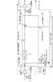
図1は、従来技術による光合分岐装置の構成の一例を示す図である。図1に示す光合分岐装置50は、海底光ケーブルシステムに利用され、光中継器31と光中継器32との間に接続される。光合分岐装置50は、中継器31から入力される波長多重光信号通信の一部の波長多重光信号をアド/ドロップ局30に分岐(ドロップ)するとともに、アド/ドロップ局30からの波長多重光信号を、中継器31と中継器32を結ぶメインルートXにおける波長多重光信号通信に挿入(アド)する。
FIG. 1 is a diagram illustrating an example of a configuration of an optical combining / branching device according to a conventional technique. 1 is used for a submarine optical cable system and is connected between an
図1に示す光合分岐装置50は、光分波器51、光フィルタ52、光合波器53を備える。光分波器51は、海底ケーブル41から入力された波長多重光信号300(波長帯域:Band A+Band B1)を、メインルートX側及びドロップルートY側にそれぞれ強度分岐する。光フィルタ52は、波長多重光信号300(Band A+Band B1)から、メインルートXに伝送される通信信号である波長帯域“Band A”の信号のみを抽出し、波長多重光信号301として出力する。光合波器53は、光フィルタ52から出力された透過信号(波長多重光信号301)と、海底ケーブル44を介してアド/ドロップ局30から出力された波長多重光信号303(波長帯域:Band B2)を合波し、波長多重光信号400(波長帯域:Band A+Band B2)として海底ケーブル42に出力する。
The optical multiplexer / demultiplexer 50 shown in FIG. 1 includes an optical demultiplexer 51, an
光合分岐装置50から分岐された波長多重光信号300は、海底ケーブル43を介して光フィルタ45に入力される。光フィルタ45は、入力される波長多重光信号300から波長帯域“Band B1”の信号のみを抽出し、波長多重光信号302(Band B1)としてアド/ドロップ局30に出力する。一方、アド/ドロップ局30は、海底ケーブル44を介して波長多重光信号(波長帯域:Band B2)を光合分岐装置50に挿入する。
The wavelength division multiplexed
以上のような構成により、光合分岐装置50は、入力された波長多重光信号300(Band A+Band B1)のうち、波長多重光信号302(Band B1)をメインルートXから分岐(ドロップ)するとともに、アド/ドロップ局30からの波長多重光信号303(Band B2)を、メインルートXに挿入(アド)し、波長多重光信号400(Band A+BandB2)として出力する。
With the configuration as described above, the optical multiplexer / demultiplexer 50 branches (drops) the wavelength multiplexed optical signal 302 (Band B1) from the main route X out of the input wavelength multiplexed optical signal 300 (Band A + Band B1). The wavelength multiplexed optical signal 303 (Band B2) from the add /
しかし、図1に示すシステムにおいて、海底ケーブル44が切断され、アド/ドロップ局30からの波長多重光信号303(Band B2)が光合分岐装置50に挿入されなくなった場合、海底ケーブル42に伝送される信号の波長数が減少(帯域幅が減少)してしまう。この場合、波長多重光信号301(Band A)における各チャネルの信号光は、光中継器32よって過大に増幅されるため、光中継器32以降の伝送路における信号品質は劣化してしまう。
However, in the system shown in FIG. 1, when the submarine cable 44 is cut and the wavelength multiplexed optical signal 303 (Band B2) from the add /
このような問題を解決するため、例えば、特開2006−180417に、光合分岐装置において挿入される信号の光強度に応じて、メインルートから分岐された信号を再度メインルートに挿入することで、メインルートを介して入出力される信号の強度を維持する光アドドロップ装置が記載されている(特許文献1参照)。 In order to solve such a problem, for example, in JP 2006-180417 A, a signal branched from the main route is inserted into the main route again in accordance with the light intensity of the signal inserted in the optical multiplexing and branching device. An optical add / drop device is described that maintains the strength of signals input and output via a main route (see Patent Document 1).
図2は、特許文献1に記載の光合分岐装置の構成を示す図である。図2を参照して、特許文献1に記載の光合分岐装置60は、波長多重光信号の一の信号(波長λ1)を分岐する光分岐スイッチ61と、光伝送装置70から出力された信号(波長λ1’)を当該波長多重光信号に挿入する光挿入スイッチ62とを備える。又、アドドロップ装置60は、光カプラ63、光スイッチ64、光アンプ65、スイッチ制御回路66、アンプ制御回路67を更に備える。
FIG. 2 is a diagram illustrating a configuration of the optical coupling / decoupling device described in
光カプラ63は、光分岐スイッチ61によって分岐された信号(波長λ1)を伝送装置70及び光スイッチ64に出力する。光スイッチ64は、光分岐スイッチ61によって分岐された信号(波長λ1)と光伝送装置70から入力された信号(λ1’)の一方を選択して出力する。光アンプ65は、光スイッチ64によって選択された信号を増幅して光挿入スイッチ62に出力する。スイッチ制御回路66は、光伝送装置70から入力される信号(波長λ1’)の信号レベルを監視し、監視結果に応じて光スイッチ64の選択動作を制御する。例えば、信号(波長λ1’)の信号レベルが規定値よりも低い場合、光スイッチ64は、光カプラ63からの信号(波長λ1)を選択出力し、規定値以上である場合、信号(波長λ1’)を選択出力する。アンプ制御回路67は、光アンプ65からの出力レベルを監視し、監視結果に応じて、光アンプ65の増幅率を変更する。
The
以上のような構成により、特許文献1に記載の光合分岐装置60は、光伝送装置70から挿入される信号(波長λ1’)の信号レベルが規定値より低い場合、光伝送装置70へ分岐出力した信号(波長λ1)をメインルートの波長多重光信号にループバックする。これにより、伝送装置70と光合分岐装置60との間の伝送路上に障害が発生しても、波長多重光信号のパワーレベル変動の発生を抑制することが可能となる。
With the configuration as described above, the optical add /
しかし、特許文献1に記載の装置では、波長単位(単一チャネル)のループバック制御しかできないため、波長バンド単位(多チャネル)の挿入信号数(波長数)が変動したときの利得変動に対応することができない。又、波長バンド単位のループバック制御を行うように特許文献1に記載の装置を変更した場合、信号毎(チャネル毎)に光スイッチ64、光アンプ65、スイッチ制御回路66、アンプ制御回路67を設ける必要がある。このため、特許文献1に記載の技術を図1に示すシステムに適用する場合、障害回避のための装置の回路規模が大きくなってしまう。又、特許文献1では、伝送路に障害が発生した場合、ループバックされた信号レベルを増幅するための光アンプ65を必要とするため、消費電力量が増大してしまう。
However, since the apparatus described in
本発明の目的は、波長多重光信号の分岐及び挿入を制御する光合分岐装置を有する光通信システムの通信品質の劣化を防止することにある。 An object of the present invention is to prevent deterioration in communication quality of an optical communication system having an optical add / drop device that controls branching and insertion of wavelength multiplexed optical signals.
本発明の他の目的は、波長多重光信号の分岐及び挿入を制御する光合分岐装置を有する光通信システムの通信品質を維持するためのコストの上昇を抑制することにある。 Another object of the present invention is to suppress an increase in cost for maintaining the communication quality of an optical communication system having an optical add / drop device that controls branching and insertion of a wavelength multiplexed optical signal.
本発明による更に他の目的は、波長多重光信号の分岐及び挿入を制御する光合分岐装置の故障発生率を低減するとともに、光伝送システムの通信品質の劣化を防止することにある。 Still another object of the present invention is to reduce the failure occurrence rate of an optical multiplexer / demultiplexer that controls the branching and insertion of a wavelength multiplexed optical signal and to prevent the communication quality of an optical transmission system from deteriorating.
上記の課題を解決するために、本発明は、以下に述べられる手段を採用する。その手段を構成する技術的事項の記述には、[特許請求の範囲]の記載と[発明を実施するための形態]の記載との対応関係を明らかにするために、[発明を実施するための形態]で使用される番号・符号が付加されている。ただし、付加された番号・符号は、[特許請求の範囲]に記載されている発明の技術的範囲を限定的に解釈するために用いてはならない。 In order to solve the above problems, the present invention employs the means described below. In the description of technical matters constituting the means, in order to clarify the correspondence between the description of [Claims] and the description of [Mode for Carrying Out the Invention] The number / symbol used in [Form] is added. However, the added numbers and symbols should not be used to limit the technical scope of the invention described in [Claims].
本発明による光合分岐装置(10)は、分波回路と第1可変減衰器(17)と合波回路とを具備する。分波回路は、第1伝送路(41)から入力された波長多重光信号(100)を、周波数帯域の異なる第1波長多重光信号(101)と第2波長多重光信号(102)とに分波する。第1可変回路(17)は、第2伝送路(44)から入力された第3波長多重光信号(103)の光レベルに応じた損失量により、第2波長多重光信号(102)を減衰する合波回路は、第1可変減衰器(17)を介して入力される第2波長多重光信号(102)と、第1波長多重光信号(101)と、第3波長多重光信号(103)とを合波して第3伝送路(42)出力する。 An optical multiplexer / demultiplexer (10) according to the present invention includes a branching circuit, a first variable attenuator (17), and a multiplexing circuit. The demultiplexing circuit converts the wavelength multiplexed optical signal (100) input from the first transmission line (41) into a first wavelength multiplexed optical signal (101) and a second wavelength multiplexed optical signal (102) having different frequency bands. Demultiplex. The first variable circuit (17) attenuates the second wavelength multiplexed optical signal (102) by the loss amount corresponding to the optical level of the third wavelength multiplexed optical signal (103) input from the second transmission line (44). The multiplexing circuit that performs the second wavelength multiplexed optical signal (102), the first wavelength multiplexed optical signal (101), and the third wavelength multiplexed optical signal (103) input via the first variable attenuator (17). ) And the third transmission path (42).
本発明による光合分岐方法は、第1伝送路(41)から入力された波長多重光信号(100)を、周波数帯域の異なる第1波長多重光信号(101)と第2波長多重光信号(102)とに分波するステップと、第1可変減衰器(17)が、第2伝送路(44)から入力された第3波長多重光信号(103)の光レベルに応じた損失量により、第2波長多重光信号(102)を減衰するステップと、第1可変減衰器(17)を介して入力される第2波長多重光信号(102)と、第1波長多重光信号(101)と、第3波長多重光信号(103)とを合波して第3伝送路(42)に出力するステップを具備する。 According to the optical multiplexing and branching method of the present invention, a wavelength multiplexed optical signal (100) input from the first transmission line (41) is divided into a first wavelength multiplexed optical signal (101) and a second wavelength multiplexed optical signal (102) having different frequency bands. ), And the first variable attenuator (17) causes the first variable attenuator (17) to perform the first loss by the amount of loss corresponding to the optical level of the third wavelength multiplexed optical signal (103) input from the second transmission line (44). Attenuating the two-wavelength multiplexed optical signal (102); a second wavelength-multiplexed optical signal (102) input through the first variable attenuator (17); and a first wavelength-multiplexed optical signal (101); And a step of combining the third wavelength multiplexed optical signal (103) and outputting it to the third transmission line (42).
以上のように、本発明による光合分岐装置(10)は、第3波長多重光信号(103)の光レベルが低下しても、第2波長多重光信号(102)により第1伝送路(41)と第3伝送路(42)を結ぶメインルート上の波長数を維持することができる。これにより、第3伝送路上に光中継器が設けられたとしても波長数変動に伴う過大な増幅を防止することができる。 As described above, the optical multiplexing / demultiplexing device (10) according to the present invention uses the second transmission line (41) by the second wavelength division multiplexed optical signal (102) even if the optical level of the third wavelength division multiplexed optical signal (103) decreases. ) And the third transmission line (42), the number of wavelengths on the main route can be maintained. As a result, even if an optical repeater is provided on the third transmission line, it is possible to prevent excessive amplification due to fluctuations in the number of wavelengths.
本発明によれば、波長多重光信号の分岐及び挿入を制御する光合分岐装置を有する光通信システムの通信品質の劣化を防止することができる。 According to the present invention, it is possible to prevent deterioration in communication quality of an optical communication system having an optical add / drop device that controls branching and insertion of wavelength multiplexed optical signals.
又、波長多重光信号の分岐及び挿入を制御する光合分岐装置を有する光通信システムの通信品質を維持するためのコストの上昇を抑制することができる。 In addition, it is possible to suppress an increase in cost for maintaining the communication quality of an optical communication system having an optical add / drop device that controls branching and insertion of wavelength multiplexed optical signals.
更に、波長多重光信号の分岐及び挿入を制御する光合分岐装置の故障発生率を低減するとともに、光伝送システムの通信品質の劣化を防止することができる。 Furthermore, it is possible to reduce the failure occurrence rate of the optical multiplexer / demultiplexer that controls the branching and insertion of the wavelength multiplexed optical signal, and to prevent the communication quality of the optical transmission system from deteriorating.
以下、添付図面を参照しながら本発明の実施の形態を説明する。図面において同一、又は類似の参照符号は、同一、類似、又は等価な構成要素を示している。本実施の形態では、光通信システム(例示:海底光ケーブルシステム)に利用され、アド/ドロップ局に対する波長多重光信号のアド/ドロップを行う光合分岐装置を一例に説明する。 Hereinafter, embodiments of the present invention will be described with reference to the accompanying drawings. In the drawings, the same or similar reference numerals indicate the same, similar, or equivalent components. In this embodiment, an optical coupling / branching device that is used in an optical communication system (example: submarine optical cable system) and adds / drops a wavelength multiplexed optical signal to / from an add / drop station will be described as an example.
1.第1の実施の形態
図3から図6を参照して、本発明による光合分岐装置の第1の実施の形態における構成及び動作の詳細を説明する。図3は、本発明による光合分岐装置の第1の実施の形態における構成の一例を示す図である。
1. First Embodiment With reference to FIG. 3 to FIG. 6, the details of the configuration and operation of a first embodiment of an optical multiplexing / branching device according to the present invention will be described. FIG. 3 is a diagram showing an example of a configuration in the first embodiment of the optical add / drop device according to the present invention.
図3を参照して、本発明による光合分岐装置10は、海底光ケーブルシステムに利用され、メインルートXとなる海底ケーブル41と海底ケーブル42との間に設けられる。光中継器31、32はメインルートXの光損失を補償するため、入力される波長多重光信号を増幅して次段の海底ケーブルに出力する。例えば、光中継器31、32は、海底ケーブルシステムにて一般的に使われる励起光一定制御によって中継器出力レベルがほぼ一定となる光アンプが好適である。
Referring to FIG. 3, the optical coupling / branching device 10 according to the present invention is used in a submarine optical cable system and is provided between a
光合分岐装置10は、光中継器31から入力される波長多重光信号通信の一部の波長多重光信号をアド/ドロップ局30に分岐(ドロップ)するとともに、アド/ドロップ局30からの波長多重光信号を、光中継器31と光中継器32を結ぶメインルートXにおける波長多重光信号通信に挿入(アド)する。以下、光合分岐装置10からアド/ドロップ局30へ波長多重光信号を取り出す(ドロップする)ためのルートをドロップルートYと称し、アド/ドロップ局30から光合分岐装置10へ波長多重光信号を挿入(アド)するためのルートをアドルートZと称す。
The optical add / drop device 10 branches (drops) a part of the wavelength multiplexed optical signal input from the
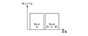
本実施の形態では、光合分岐装置10は、波長帯域“Band A+Band B1”の波長多重光信号100から、ドロップルートYに波長帯域“Band B1”の波長多重光信号102がドロップされる。又、メインルートXには波長帯域“Band A”の波長多重光信号101が出力されるとともに、アドルートZから波長帯域“Band B2”の波長多重光信号103が挿入される。図4は、本発明に係る波長多重光信号の使用波長帯域の一例を示す波長配置図である。図4を参照して、“Band B1”と“Band B2”は同一の波長帯域とし、“Band A”は“Band B1(B2)”と異なる波長帯域に配置することが好ましい。又、“Band A”の波長帯域内でない限り、“Band B1”と“Band B2”はそれぞれ別の波長帯域としてもよい。
In the present embodiment, the optical multiplexing / demultiplexing device 10 drops the wavelength multiplexed
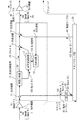
図3に示す光合分岐装置10は、光分波器11、12、18、光フィルタ13、16、光合波器14、15、光可変減衰器17、光検出器19を備える。光中継器31から出力された波長多重光信号100(波長帯域:Band A+BandB1)は、海底ケーブル41を介して光分波器11に入力される。光分波器11は、波長多重光信号100(Band A+Band B1)を強度分岐し、メインルートX側の光分波器12とドロップルートY側の光フィルタ45に出力する。光分波器12は、メインルートX側に出力される波長多重光信号100を強度分岐し、光フィルタ13と光フィルタ16に出力する。光フィルタ13は、波長多重光信号100(Band A+Band B1)からメインルートXの通信信号である波長帯域“Band A”のみを透過し、波長多重光信号101として光合波器14に出力する。一方、光フィルタ16は、波長多重光信号100(Band A+Band B1)から、ドロップルートYにドロップする通信信号と同じ波長帯域“Band B1”のみを透過し、波長多重光信号102として光可変減衰器17に出力する。波長多重光信号102は、光可変減衰器17を介して光合波器14に入力される。光可変減衰器17は、波長多重光信号102の光レベル(光フィルタ16の出力レベル)を減衰し、光合波器14に対する波長多重光信号102の入力レベルを決定する。光可変減衰器17による減衰量(損失量)は、光検出器19からの制御信号110によって設定される。
The optical multiplexer / demultiplexer 10 shown in FIG. 3 includes
光合波器14は、光フィルタ13からの出力信号と光可変減衰器17からの出力信号とを強度合波して光合波器15に出力する。一方、光分波器18は、アド/ドロップ局30から海底ケーブル44を介して出力された波長多重光信号103(波長帯域:Band B2)を強度分岐し、光合波器15と光検出器19に出力する。例えば、光分波器18は、波長多重光信号103のトータルパワーを所定の割合で強度分岐し、光合波器15と光検出器19に出力する。あるいは、光分波器18は、波長多重光信号103における特定波長のチャネルパワーを所定の割合で強度分岐し、光合波器15と光検出器19に出力する。光合波器15は、光合波器14からの出力信号と、光分波器18からの出力信号とを強度合波し、海底ケーブル42を介して光中継器32に出力する。
The optical multiplexer 14 combines the output signal from the
光検出器19は、光分波器18からの出力(波長多重光信号103)の光レベルを監視し、監視結果に応じた制御信号110を光可変減衰器17に出力する。例えば、光検出器19は、海底ケーブル44を通る波長帯域全体から光分波器8によって切り取られた波長多重光信号103における波長範囲全体のトータルパワーを監視する。あるいは、光検出器19は、海底ケーブル44を通る特定の波長の光レベルを監視する。光検出器19には、図5に示されるような閾値が設定され、監視光(例えば波長多重光信号103)の光レベルが閾値以上であるか否かを監視する。ここで設定される閾値は、波長多重光信号103の光合分岐装置10への入力が遮断されたとみなし得る光レベルが設定されることが好ましい。
The
波長多重光信号103又は特定の波長の監視光の光レベルが閾値以上である場合、光検出器19は、光可変減衰器17の損失が最大(所定の値以上、好ましくは無限大)となるように制御する。これにより、光合波器14への波長多重光信号102の入力は遮断され、光合波器14は、波長多重光信号101(Band A)のみを光合波器15に出力する。この場合、光合波器15は、波長多重光信号101とアド/ドロップ局30からの波長多重光信号103とを強度合波し、波長帯域が“Band A+Band B2”の波長多重光信号200をメインルートXの海底ケーブル42に出力する。一方、波長多重光信号103の光レベルが閾値を下回る場合、光検出器19は、光可変減衰器17の損失が最小(所定の値より小さな値、好ましくは損失0)となるように制御する。これにより、光合波器14には波長多重光信号102が入力され、光合波器14は、波長多重光信号101(Band A)と波長多重光信号102(Band B1)を強度合波した波長多重光信号201(波長帯域:Band A+Band B1)を出力する。光合波器15は、波長多重光信号201と波長多重光信号103とを強度合波するが、波長多重光信号103の光レベルは閾値よりも低いため、実質的に波長帯域が“Band A+Band B1”の波長多重光信号201をメインルートXの海底ケーブル42に出力することとなる。尚、光検出器19に大きな閾値が設定された場合、当該閾値を下回る波長多重光信号103の光レベルが無視できない大きさ(実質的に0とみなせない大きさ)となる。この場合、光可変減衰器17は、光合波器15に入力される波長多重光信号103の大きさを考慮した減衰率で波長多重光信号102を減衰することが好ましい。例えば、光可変減衰器17は、海底ケーブル42におけるBand Aのチャンネルパワーが海底ケーブル44における障害前後で変化しないよう、海底ケーブル42における“Band B1 と Band B2 のトータルパワーを、当該障害前の波長多重光信号102(Band B1)のチャネルパワーと一致するように調整する。
When the optical level of the wavelength multiplexed
上述では、波長多重光信号103の光合分岐装置10への入力が遮断されたとみなし得る光レベルが、閾値として設定され、波長多重光信号103の光レベルが閾値を下回る場合、光可変減衰器の損失を0とするように制御することを一例とした。しかし、閾値の大きさはこれに限らず、所定の光レベルが閾値として設定されても構わない。この場合、光合波器15から出力される波長多重光信号のうち、メインルートXにおける通信(Band A)以外の波長帯域の波長多重光信号の光レベルが当該閾値以上となるように、光可変減衰器17の減衰量が設定されることが好ましい。例えば、図5を参照して、閾値が“a”に設定され、光検出器19で監視された波長多重光信号103の光レベルが“b”(a>b)である場合、光可変減衰器17から出力される波長多重光信号102の光レベルを“b−a”以上の“c”とすることで、光合波器15から出力される波長多重光信号201(波長帯域:Band A+Band B1+BandB2)から波長帯域“BandA”を除く波長帯域“Band B1+Band B2)”の光レベルを閾値“a”以上とすることができる。
In the above description, when the optical level that can be regarded as the input of the wavelength division multiplexed
以上のような構成により、第1の実施の形態のおける光合分岐装置10は、入力された波長多重光信号100(Band A+Band B1)のうち、波長多重光信号102(Band B1)をメインルートXから分岐(ドロップ)するとともに、アド/ドロップ局30からの波長多重光信号103(Band B2)を、メインルートXに挿入(アド)し、波長多重光信号200(Band A+Band B2)として出力する。又、第1の実施の形態のおける光合分岐装置10は、アド/ドロップ局30から挿入される波長多重光信号103(Band B2)の光レベル(光パワ)が閾値より低い場合、アド/ドロップ局30へ分岐出力した波長多重光信号102(Band B1)をメインルートXの波長多重光信号に合波する。これにより、海底ケーブル44やアド/ドロップ局30の障害によって波長多重光信号103(Band B2)が光合分岐装置10に挿入されない場合でも、海底ケーブル42に伝送する波長多重光信号の波長数(帯域幅)は減少しない。このため、中継器32は、光波長多重光信号101(Band A)における各チャネルの信号光を過大に増幅することなく、光中継器32以降の伝送路における通信品質を維持することができる。すなわち、本発明によれば、光合分岐装置10とアド/ドロップ局30との間の伝送路上に障害が発生しても、メインルートXにおける波長多重光信号101(Band A)のパワーレベル変動が抑制され、通信品質の低下を防止することができる。
With the configuration as described above, the optical add / drop device 10 in the first embodiment transmits the wavelength multiplexed optical signal 102 (Band B1) out of the input wavelength multiplexed optical signal 100 (Band A + Band B1) to the main route X. The wavelength multiplexed optical signal 103 (Band B2) from the add /
又、本発明では、減衰器を利用してメインルートX上の波長多重光信号に合波する波長多重光信号を決定しているため、回路規模を大きくすることなく波長バンド単位(多チャネル)の挿入信号数(波長数)の変動による利得変動に対応することが可能となる。更に、本発明では、メインルートXにおける波長多重光信号101と波長多重光信号102の損失には大きな差がないため、メインルートX上の波長多重光信号に合波した波長多重光信号102を増幅する光アンプを必要としない。このため、本発明によれば、通信品質を維持するための動作に係る消費電力を低減することができる。又、従来技術のようにスイッチを設ける場合と異なり、減衰器を利用しているため、光スイッチのような機械動作するデバイスを利用せず構成が簡略化される。又、構成が簡単で故障率の高いデバイスが少ないため、故障の発生率が従来よりも低下する。このため、本発明による光合分岐装置10を利用することで光伝送システムの信頼性を向上させることができる。
In the present invention, since the wavelength multiplexed optical signal to be multiplexed with the wavelength multiplexed optical signal on the main route X is determined using an attenuator, the wavelength band unit (multi-channel) is used without increasing the circuit scale. Thus, it is possible to cope with gain fluctuations due to fluctuations in the number of inserted signals (number of wavelengths). Furthermore, in the present invention, since there is no significant difference in the loss between the wavelength multiplexed optical signal 101 and the wavelength multiplexed
(動作)
次に、図3に示す光合分岐装置10の動作の詳細を説明する。
(Operation)
Next, details of the operation of the optical add / drop device 10 shown in FIG. 3 will be described.
先ず、海底ケーブルシステムが通常運用している状態(障害未発生)における動作を説明する。海底ケーブル41から光合分岐装置10に入力される波長多重光信号100(Band A+Band B1)は光分波器11にてメインルートX及びドロップルートYにそれぞれ強度分岐される。光分波器11から海底ケーブル43に出力される波長多重光信号100(Band A+Band B1)は、光フィルタ45によりドロップルートYの通信に必要な波長多重光信号102(Band B1)のみ抽出された後、アド/ドロップ局30に出力される。光合分波器10にてメインルートX側に分岐された波長多重光信号100(Band A1+Band B1)は光分波器12にて光フィルタ13および光フィルタ16にそれぞれ強度分岐される。光フィルタ13は、波長多重光信号100(Band A+Band B1)から、波長多重光信号101(Band A)のみを透過する。一方、光フィルタ16は、波長多重光信号100(Band A+Band B1)から、波長多重光信号102(Band B1)のみを透過し、光可変減衰器17に出力する。
First, the operation in a state where the submarine cable system is normally operated (no failure has occurred) will be described. The wavelength multiplexed optical signal 100 (Band A + Band B1) input from the
通常状態において、光検出器19にて検出される光モニタレベルは、断検出閾値を上回る光レベルを検出している。このときの制御信号110によって、光可変減衰器17の損失量が最大損失となるように制御される。これにより、光フィルタ16から透過された波長多重光信号102(Band B1)は、光可変減衰器17からは出力されなくなる。この場合、光合波器14は、光フィルタ13からの波長多重光信号101(Band A)のみを光合波器15に出力する。一方、アド/ドロップ局30から海底ケーブル44を介して光合分岐装置10に入力される波長多重光信号103(Band B2)は、光分波器18を介して光合波器15に出力される。光合波器15は、光合波器14からの波長多重光信号101(Band A)と光分波器18からの波長多重光信号103(Band B2)を合波し、波長多重光信号200(Band A+Band B2)として海底ケーブル42に送信する。以上の動作によって、光合分岐装置10は、波長多重光信号102(Band B1)をメインルートXよりドロップし、波長多重光信号103(Band B2)をメインルートXにアドする。
In the normal state, the light monitor level detected by the
次に分岐ルート(アドルートZ)である海底ケーブル44が切断される障害が起こった際の動作を説明する。海底ケーブル44が切断される障害が起こった場合、光検出器19にて検出される波長多重光信号103(Band B2)のモニタ光が断となる。モニタ光が断になった場合、当該モニタ光が閾値を下回るため光検出器19は波長多重光信号103が断であると判定し、制御信号110を用いて、光可変減衰器17の損失を低下させる。これにより、波長多重光信号102(Band B1)は光可変減衰器17から透過され、光合波器14にて光フィルタ13からの波長多重光信号101(Band A)と合波される。光合波器15では光分波器18からの入力光がないため、光合波器14からの波長多重光信号201(Band A+B1)のみが海底ケーブル42へ出力される。よって、海底ケーブル42では、障害によって波長多重光信号103(Band B2)がなくなっても、波長数が減少しないため、メインルートXの通信信号である波長多重光信号101(Band A)の各チャネルの信号光パワーは過大に高くならず、信号品質の劣化を抑えることができる。
Next, an operation when a failure occurs in which the submarine cable 44 that is a branch route (add route Z) is disconnected will be described. When a failure occurs in which the submarine cable 44 is disconnected, the monitoring light of the wavelength multiplexed optical signal 103 (Band B2) detected by the
以上のように、本発明によれば、アドルートZ上の伝送路(海底ケーブル44)上を伝播された波長多重光信号の光レベル(光パワー)を監視し、監視結果に応じて、ドロップした波長多重光信号102をメインルートX上の波長多重光信号101に合波することで、メインルートXの波長数を維持し、通信品質の劣化を防止することができる。
As described above, according to the present invention, the optical level (optical power) of the wavelength multiplexed optical signal propagated on the transmission path (submarine cable 44) on the add route Z is monitored, and dropped according to the monitoring result. By multiplexing the wavelength multiplexed
図6は、本発明による光合分岐装置の第1の実施の形態における構成の他の一例を示す図である。図3に示す一例では、ドロップした波長多重光信号光分波器102をメインルートXの波長多重光信号に合波するために分波器12及び光フィルタ16を用いたが、これ替えて、図6に示す波長分岐器20を用いても良い。この場合、波長分岐器20は、波長多重光信号100(Band A+Band B1)を波長多重光信号101(Band A)と波長多重光信号102(Band B1)に波長分岐する。
FIG. 6 is a diagram showing another example of the configuration of the first embodiment of the optical add / drop device according to the present invention. In the example shown in FIG. 3, the demultiplexer 12 and the
又、同様に、図3に示す光合分岐装置10では、光分波器11や光合波器14、15として強度分波器や強度合波器を用いているが、これに限らず、波長を分波又は合波する波長分波器や波長合波器を用いても構わない。この場合、光フィルタ45、13は不要になることは言うまでもない。
Similarly, in the optical multiplexer / demultiplexer 10 shown in FIG. 3, an intensity demultiplexer or an intensity multiplexer is used as the optical demultiplexer 11 or the optical multiplexers 14, 15. A wavelength demultiplexer or a wavelength multiplexer that demultiplexes or multiplexes may be used. In this case, it goes without saying that the
2.第2の実施の形態
図7から図9を参照して本発明による光合分岐装置の第2の実施の形態における構成及び動作を説明する。第2の実施の形態における光合分岐装置10には、ドロップされる波長多重光信号102と同じ波長帯域の波長多重光信号103(Band B2)が挿入(アド)されるとともに、メインルートX上の波長多重光信号101(Band A)と同じ波長帯域“Band C”のダミー光(波長多重光信号105)が選択的に挿入(アド)される。第2の実施の形態では、アドされる波長多重光信号103の光レベルに応じて波長多重光信号102をメインルートX上の波長多重光信号に合波させる制御に加え、メインルートX上の波長多重光信号101の光レベルに応じて、波長多重光信号105を挿入(アド)する制御が行われる。
2. Second Embodiment With reference to FIG. 7 to FIG. 9, the configuration and operation of a second embodiment of the optical coupling / branching device according to the present invention will be described. In the optical add / drop device 10 in the second embodiment, a wavelength multiplexed optical signal 103 (Band B2) having the same wavelength band as the dropped wavelength multiplexed
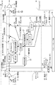
図7は、本発明による光合分岐装置の第2の実施の形態における構成の一例を示す図である。以下では、第1の実施の形態と異なる構成及び動作について詳細に説明する。 FIG. 7 is a diagram showing an example of the configuration of the optical add / drop device according to the second embodiment of the present invention. Hereinafter, a configuration and operation different from those of the first embodiment will be described in detail.
図7に示す光合分岐装置10は、図3に示す光合分岐装置10の構成に加えて、光分波器21、光検出器22、光フィルタ24、26、光合波器25、光可変減衰器27を備える。又、図7に示すアド/ドロップ局30は、波長多重光信号101の波長帯域Band Aと同じ波長帯域“Band C”の波長多重光信号105と波長多重光信号103(Band B2)を含む波長多重光信号104を光合分岐装置10に対して出力する。その他の構成は、第1の実施の形態と同様である。
7 includes an
光分波器11は、波長多重光信号100(Band A+Band B1)を強度分岐し、メインルートX側の光分波器21とドロップルートY側の光フィルタ45に出力する。光分波器21は、メインルートX側に出力される波長多重光信号100を強度分岐し、光フィルタ光分波器12と光検出器22に出力する。光検出器22は、光分波器21からの出力(波長多重光信号100)の光レベルを監視し、監視結果に応じた制御信号111を光可変減衰器27に出力する。光検出器22には、図8に示されるような閾値が設定され、波長多重光信号100(Band A +Band B1)の光レベルが閾値以上であるか否かを監視する。ここで設定される閾値は、波長多重光信号100の光合分岐装置10への入力が遮断されたとみなし得る光レベルが設定されることが好ましい。
The optical demultiplexer 11 splits the intensity of the wavelength-multiplexed optical signal 100 (Band A + Band B1) and outputs it to the
一方、第2の実施の形態における光分波器18は、アド/ドロップ局30から海底ケーブル44を介して出力された波長多重光信号104(Band C+Band B2)を強度分岐し、光分波器23と光検出器19に出力する。光分波器23は、アドルートY側に出力される波長多重光信号104を強度分岐し、光フィルタ24と光フィルタ26に出力する。光フィルタ24は、波長多重光信号104(Band C+Band B2)からアドルートYの通信信号である波長帯域“Band B2”のみを透過し、波長多重光信号103として光合波器25に出力する。一方、光フィルタ26は、波長多重光信号104(Band C+Band B2)から、メインルートXの通信信号と同じ波長帯域“Band C”のみを透過し、波長多重光信号105として光可変減衰器27に出力する。波長多重光信号105は、光可変減衰器27を介して光合波器25に入力される。光可変減衰器27は、波長多重光信号105の光レベル(光フィルタ26の出力レベル)を減衰し、光合波器25に対する波長多重光信号105の入力レベルを決定する。光可変減衰器27による減衰量(損失量)は、光検出器22からの制御信号111によって設定される。
On the other hand, the
波長多重光信号100の光レベルが閾値以上である場合、光検出器22は、光可変減衰器27の損失が最大となるように制御する。これにより、光合波器25への波長多重光信号105の入力は遮断され、光合波器25は、波長多重光信号103(Band B2)のみを光合波器15に出力する。この場合、光合波器15は、波長多重光信号101とアド/ドロップ局30からの波長多重光信号103とを強度合波し、波長帯域が“Band A+Band B2”の波長多重光信号200をメインルートXの海底ケーブル42に出力する。一方、波長多重光信号100の光レベルが閾値を下回る場合、光検出器22は、光可変減衰器27の損失が最小(好ましくは損失0)となるように制御する。これにより、光合波器25には波長多重光信号105が入力され、光合波器25は、波長多重光信号105(Band C)と波長多重光信号103(Band B2)を強度合波した波長多重光信号104(波長帯域:Band C+Band B2)を出力する。光合波器15は、波長多重光信号201と波長多重光信号104とを強度合波するが、波長多重光信号201の光レベルは閾値よりも低いため、実質的に波長帯域が“Band C+Band B2”の波長多重光信号202をメインルートXの海底ケーブル42に出力することとなる。
When the optical level of the wavelength-multiplexed
第2の実施の形態における光検出器19は、波長多重光信号104(Band C+BandB2)の光レベルに応じて光可変減衰器17の減衰量(損失量)を制御する。減衰量の制御方法は、光検出器22と同様であり、図8に示すように閾値と波長多重光信号104(Band C+BandB2)との比較結果に応じて光可変減衰器17の減衰量を決定する。その他、光分波器12、光フィルタ13、16、光合波器15の各動作は、第1の実施の形態と同様である。
The
以上のような構成により、第2の実施の形態における光合分岐装置10では、海底ケーブル41の障害等によって波長多重光信号100(Band A+Band B1)が光合分岐装置10に挿入されない場合、アド/ドロップ局30から波長帯域“Band A”に相当する波長帯域“Band C”のダミー光(波長多重光信号105)が送信される。このため、海底ケーブル41が断となる障害が発生して場合、海底ケーブル42に伝送する波長多重光信号の波長数(帯域幅)は減少せず、アドルートZの信号品質を確保することが可能となる。又、第1の実施の形態と同様に、海底ケーブル44やアド/ドロップ局30の障害によって波長多重光信号103(Band B2)が光合分岐装置10に挿入されない場合でも、海底ケーブル42に伝送する波長多重光信号の波長数(帯域幅)は減少しないため、メインルートXの通信品質の劣化を防止することができる。すなわち、第2の実施の形態における光合分岐装置10によれば、アドルートZに障害が発生してもメインルートXの通信品質の低下を防止できるとともに、メインルートXに障害が発生してもアドルートZの通信品質の低下を防止できる。
With the configuration as described above, in the optical add / drop device 10 according to the second embodiment, when the wavelength multiplexed optical signal 100 (Band A + Band B1) is not inserted into the optical add / drop device 10 due to a failure in the
3.第3の実施の形態
図9は、第3の実施の形態における光合分岐装置10の構成を示す図である。図9に示すように、本願発明による光合分岐装置10は、ドロップルートYやアドルートZ上に中継器46、47が設けられた場合にも適用できる。第3の実施の形態における光合分岐装置10は、光分波器18に対して海底ケーブル44側にダミー光(波長帯域:Band C)を遮断する光フィルタ28を備え、その他の構成は、図3に示す構成と同様である。
3. Third Embodiment FIG. 9 is a diagram illustrating a configuration of an optical add / drop device 10 according to a third embodiment. As shown in FIG. 9, the optical add / drop device 10 according to the present invention can also be applied when repeaters 46 and 47 are provided on the drop route Y and the add route Z. The optical add / drop device 10 according to the third embodiment includes an
本実施の形態では、海底ケーブル44に、光中継器31、32と同じ能力(例えば出力パワ)の光中継器47が設けられている。この場合、アド信号である波長多重光信号(波長帯域:Band B2)のみが入力されると、光中継器47によって海底ケーブル44における信号のチャンネルパワーが必要以上に高くなり、光合波器15において合波した信号は劣化する可能性がある。このため本実施の形態では、波長多重光信号(Band B2)の光レベルを一定に保つため、アド信号である波長多重光信号(波長帯域:Band B2)に加えて、ダミー光(波長帯域:Band C)が海底ケーブル44に挿入される。すなわち、本実施の形態におけるアド/ドロップ局30は、アド信号である波長多重光信号(Band B2)と、ダミー光(Band C)を含む波長多重光信号104を海底ケーブル44に出力する。
In the present embodiment, an optical repeater 47 having the same capability (for example, output power) as the
ダミー光(Band C)は、海底ケーブル44における波長多重光信号(Band B2)のチャネルパワーを一定に保持するために挿入される。このため、ダミー光(Band C)は、少なくとも、波長帯域“Band B1、B2”以外の波長帯域に配置される。好ましくは、ダミー光(Band C)は、波長多重光信号101の波長帯域“Band A”と同一の波長帯域の波長多重光信号である。 The dummy light (Band C) is inserted in order to keep the channel power of the wavelength multiplexed optical signal (Band B2) in the submarine cable 44 constant. For this reason, the dummy light (Band C) is arranged at least in a wavelength band other than the wavelength bands “Band B1, B2”. Preferably, the dummy light (Band C) is a wavelength multiplexed optical signal having the same wavelength band as the wavelength band “Band A” of the wavelength multiplexed optical signal 101.
光フィルタ28は、中継器47を介して入力される波長多重光信号104のうち、ダミー光(Band C)を阻止し、波長多重光信号(Band B2)を透過する。光フィルタ28を透過した光は、光分波器18によって分岐され、光合波器15にて海底ケーブル18に合波されるとともに、光検出器19に入力される。光分波器18以降の構成の動作は、図3に示す構成と同様である。
The
以上のように、本実施の形態による光合分岐装置10では、アド信号の光レベルを一定に保つためのダミー光を含む波長多重光信号が入力されても、第1の実施の形態と同様に、アドルートZ上の信号劣化に応じて、ドロップした波長多重光信号102をメインルートX上の波長多重光信号101に合波し、メインルートXにおける通信品質の劣化を防止することができる。
As described above, in the optical add / drop device 10 according to the present embodiment, even if a wavelength multiplexed optical signal including dummy light for keeping the optical level of the add signal constant is input, the same as in the first embodiment. In response to the signal degradation on the add route Z, the dropped wavelength multiplexed
尚、図9において光中継器46、47は、それぞれ1台しか記載されていないが、海底ケーブル43、44には同様の光中継器が複数存在してもよい。 In FIG. 9, only one optical repeater 46, 47 is shown, but a plurality of similar optical repeaters may exist in the submarine cables 43, 44.
以上のように、本発明による光合分岐装置10は、アドルートZにおける海底ケーブル44の断の検出に応じて、アド信号(波長多重光信号103)と同じ周波数帯域の波長多重光信号102をメインルートXの波長多重信号101に合波する。これにより、メインルートXの信号光パワーの変動(利得変動)が抑制され、通信品質の劣化を防止することができる。この際、メインルート信号である波長多重光信号101とともに海底ケーブル41から入力される波長多重光信号102を、アド信号(波長多重光信号103)の代わりとなるダミー光として用いているため、特別なダミー光光源の設置が不要となる。
As described above, the optical add / drop device 10 according to the present invention uses the wavelength-division multiplexed
更に、障害発生時にメインルートX上の波長多重光信号に合波するダミー光を光減衰器によって制御しているため、波長毎(チャネル毎)にアンプやスイッチを設ける必要がなく、従来技術に比べて回路規模や消費電力を小さくすることができる。又、回路構成が従来よりも簡素化されるため、故障発生率が減少し、信頼性が向上する。 Furthermore, since the dummy light combined with the wavelength multiplexed optical signal on the main route X is controlled by the optical attenuator when a failure occurs, it is not necessary to provide an amplifier or a switch for each wavelength (each channel). Compared to this, the circuit scale and power consumption can be reduced. Further, since the circuit configuration is simplified as compared with the conventional one, the failure occurrence rate is reduced and the reliability is improved.
以上、本発明の実施の形態を詳述してきたが、具体的な構成は上記実施の形態に限られるものではなく、本発明の要旨を逸脱しない範囲の変更があっても本発明に含まれる。上述の実施の形態では光ファイバを伝送路とした海底ケーブルシステムに利用される光合分岐装置について説明したが、他のシステムにも適用できる。例えば、メインルートX、ドロップルートY、アドルートZのいずれかを光回線ではなく電気的回線(自由空間を含む)としてもよい。この場合、光合分岐装置10は、光電変換器を用いて伝送路との間の通信を行うことは言うまでもない。 The embodiment of the present invention has been described in detail above, but the specific configuration is not limited to the above-described embodiment, and changes within a scope not departing from the gist of the present invention are included in the present invention. . In the above-described embodiment, the optical coupling / branching device used in the submarine cable system using the optical fiber as the transmission path has been described. However, the present invention can be applied to other systems. For example, any one of the main route X, the drop route Y, and the add route Z may be an electrical line (including free space) instead of an optical line. In this case, it goes without saying that the optical add / drop device 10 performs communication with the transmission line using a photoelectric converter.
又、合波回路(回路光合波器14と光合波器15)の順は上述の一例に限らず、逆順に合波しても構わない。例えば、図3又は図6において、波長多重光信号101と波長多重光信号103とを合波した結果と、光可変減衰器17の出力とを合波して海底ケーブル42に出力してもよい。あるいは、図7又は図9において、波長多重光信号101と光合波器25の出力との合波結果と、光可変減衰器17の出力とを合波して海底ケーブル42に出力してもよい。
Further, the order of the multiplexing circuit (the circuit optical multiplexer 14 and the optical multiplexer 15) is not limited to the above example, and may be combined in the reverse order. For example, in FIG. 3 or FIG. 6, the result of combining the wavelength multiplexed optical signal 101 and the wavelength multiplexed
更に、上述の実施の形態においてドロップ信号を抽出する光フィルタ45は、光合分岐装置10の外部に設けられているが、これに限らず光合分岐装置10内に設けられてもよいし、アド/ドロップ局30に設けられても良い。
Furthermore, although the
10:光合分岐装置
11、12、18、23:光分波器
13、16、24、26、45:光フィルタ
14、15、21、25:光合波器
17、27:光可変減衰器
19、22:光検出器
20:波長分岐器
30:アド/ドロップ局
31、32、40:光中継器
41、42、43、44、:海底ケーブル
100、101、102、103、104、105:波長多重光信号
110、111:制御信号
10: Optical multiplexer /
Claims (10)
第2伝送路から入力された第3波長多重光信号の光レベルに応じた損失量により、前記第2波長多重光信号を減衰する第1可変減衰器と、
前記第1可変減衰器を介して入力される前記第2波長多重光信号と、前記第1波長多重光信号と、前記第3波長多重光信号とを合波して第3伝送路に出力する合波回路と
を具備する
光合分岐装置。 A demultiplexing circuit for demultiplexing the wavelength multiplexed optical signal input from the first transmission path into a first wavelength multiplexed optical signal and a second wavelength multiplexed optical signal having different frequency bands;
A first variable attenuator for attenuating the second wavelength-multiplexed optical signal by an amount of loss corresponding to the optical level of the third wavelength-multiplexed optical signal input from the second transmission line;
The second wavelength multiplexed optical signal, the first wavelength multiplexed optical signal, and the third wavelength multiplexed optical signal input through the first variable attenuator are combined and output to the third transmission line. An optical multiplexing / branching device comprising a multiplexing circuit.
前記第2波長多重光信号は、第4伝送路に出力され、
前記第3波長多重光信号の周波数帯域は前記第2波長多重光信号と同一である
光合分岐装置。 The optical coupling / branching device according to claim 1,
The second wavelength multiplexed optical signal is output to a fourth transmission line,
The optical multiplexing / branching device, wherein a frequency band of the third wavelength multiplexed optical signal is the same as that of the second wavelength multiplexed optical signal.
前記第3波長多重光信号の光レベルを監視する光検出器を更に具備し、
前記光検出器は、前記第3波長多重光信号の光レベルが閾値以上である場合、前記損失量が所定の値以上となるように前記第1可変減衰器を制御し、前記第3波長多重光信号の光レベルが閾値を下回る場合、前記損失量が所定の値より小さくなるように前記第1可変減衰器を制御する
光合分岐装置。 In the optical coupling / branching device according to claim 1 or 2,
A photodetector for monitoring an optical level of the third wavelength-multiplexed optical signal;
The optical detector controls the first variable attenuator so that the loss amount is equal to or greater than a predetermined value when the optical level of the third wavelength multiplexed optical signal is equal to or greater than a threshold, and the third wavelength multiplexed An optical coupling / branching device that controls the first variable attenuator so that the loss amount becomes smaller than a predetermined value when an optical level of an optical signal is lower than a threshold value.
前記光検出器は、前記第3波長多重光信号の光レベルが閾値を下回る場合、前記損失量が0となるように前記第1可変減衰器を制御する
光合分岐装置。 The optical coupling / branching device according to claim 3,
The optical detector is configured to control the first variable attenuator so that the loss amount becomes zero when the optical level of the third wavelength multiplexed optical signal is lower than a threshold value.
前記第3波長多重光信号を第1出力信号および第2出力信号に分波する別の分波回路と、
前記第1出力信号の第1波長帯域のみを透過してダミー信号を出力する第1光フィルタと、
前記第2出力信号の、前記第1波長帯域とは異なる第2波長帯域のみを透過して別の波長多重光信号を出力する第2光フィルタと、
前記第1伝送路から入力された前記波長多重光信号の光レベルに応じた損失量によって、前記ダミー信号を減衰する第2可変減衰器と、
前記別の波長多重光信号および前記第2可変減衰器を介して入力する前記ダミー信号を合波して別の第3波長多重光信号を出力する別の合波回路と
を更に具備し、
前記合波回路は、前記第1可変減衰器を介して入力される前記第2波長多重光信号と、前記第1波長多重光信号と、前記別の合波回路を介して入力される前記別の第3波長多重光信号とを合波して前記第3伝送路に出力する
光合分岐装置。 The optical coupling / branching device according to claim 1,
Another demultiplexing circuit for demultiplexing the third wavelength multiplexed optical signal into a first output signal and a second output signal;
A first optical filter that transmits only a first wavelength band of the first output signal and outputs a dummy signal;
A second optical filter that transmits only the second wavelength band different from the first wavelength band of the second output signal and outputs another wavelength multiplexed optical signal;
A second variable attenuator for attenuating the dummy signal by a loss amount according to an optical level of the wavelength-multiplexed optical signal input from the first transmission line ;
Further comprising a separate multiplexing circuit outputting another third wavelength-multiplexed optical signal to the dummy signal inputted through said other wavelength-multiplexed optical signal and the second variable attenuator multiplexed to,
The multiplexing circuit includes a second wavelength division multiplexed optical signals inputted through said first variable attenuator, and the first wavelength-multiplexed optical signal, said further input via said further multiplexing circuit An optical multiplexing / branching device for combining the third wavelength multiplexed optical signal and outputting the multiplexed signal to the third transmission line.
前記第1伝送路から入力された前記波長多重光信号の光レベルを監視する第1光検出器と、
前記第3波長多重光信号の光レベルを監視する第2光検出器と
を更に具備し、
前記第1光検出器は、前記波長多重光信号の光レベルが閾値以上である場合、前記損失量が所定の値以上となるように前記第2可変減衰器を制御し、前記波長多重光信号の光レベルが閾値を下回る場合、前記損失量が所定の値より小さくなるように前記第2可変減衰器を制御し、
前記第2光検出器は、前記第3波長多重光信号の光レベルが閾値以上である場合、前記損失量が所定の値以上となるように前記第1可変減衰器を制御し、前記第3波長多重光信号の光レベルが閾値を下回る場合、前記損失量が所定の値より小さくなるように前記第1可変減衰器を制御する
光合分岐装置。 The optical coupling / branching device according to claim 5,
A first photodetector for monitoring an optical level of the wavelength multiplexed optical signal input from the first transmission line ;
A second photodetector for monitoring the optical level of the third wavelength multiplexed optical signal,
The first photodetector controls the second variable attenuator so that the loss amount is equal to or greater than a predetermined value when the optical level of the wavelength-multiplexed optical signal is equal to or greater than a threshold value, and the wavelength-multiplexed optical signal The second variable attenuator is controlled so that the amount of loss is smaller than a predetermined value when the light level of
The second photodetector controls the first variable attenuator so that the loss amount is equal to or greater than a predetermined value when the optical level of the third wavelength multiplexed optical signal is equal to or greater than a threshold value. An optical multiplexing / branching device that controls the first variable attenuator so that the loss amount becomes smaller than a predetermined value when the optical level of the wavelength multiplexed optical signal is lower than a threshold value.
第1可変減衰器が、第2伝送路から入力された第3波長多重光信号の光レベルに応じた損失量により、前記第2波長多重光信号を減衰するステップと、
前記第1可変減衰器を介して入力される前記第2波長多重光信号と、前記第1波長多重光信号と、前記第3波長多重光信号とを合波して第3伝送路に出力するステップと
を具備し、
前記第2波長多重光信号は、第4伝送路に出力され、
前記第3波長多重光信号の周波数帯域は前記第2波長多重光信号と同一である
光合分岐方法。 Demultiplexing the wavelength multiplexed optical signal input from the first transmission path into a first wavelength multiplexed optical signal and a second wavelength multiplexed optical signal having different frequency bands;
A first variable attenuator attenuating the second wavelength-multiplexed optical signal by a loss amount according to the optical level of the third wavelength-multiplexed optical signal input from the second transmission path;
The second wavelength multiplexed optical signal, the first wavelength multiplexed optical signal, and the third wavelength multiplexed optical signal input through the first variable attenuator are combined and output to the third transmission line. Comprising steps,
The second wavelength multiplexed optical signal is output to a fourth transmission line,
The optical multiplexing and branching method, wherein a frequency band of the third wavelength multiplexed optical signal is the same as that of the second wavelength multiplexed optical signal.
前記第3波長多重光信号の光レベルを監視するステップと、
前記第3波長多重光信号の光レベルが閾値以上である場合、前記損失量が所定の値以上となるように前記第1可変減衰器を制御するステップと、
前記第3波長多重光信号の光レベルが閾値を下回る場合、前記損失量が所定の値より小さくなるように前記第1可変減衰器を制御するステップと
を更に具備する
光合分岐方法。 The optical coupling / branching method according to claim 7,
Monitoring the optical level of the third wavelength multiplexed optical signal;
When the optical level of the third wavelength multiplexed optical signal is equal to or greater than a threshold, controlling the first variable attenuator so that the loss amount is equal to or greater than a predetermined value;
And a step of controlling the first variable attenuator so that the loss amount becomes smaller than a predetermined value when the optical level of the third wavelength multiplexed optical signal is lower than a threshold value.
前記第3波長多重光信号を第1出力信号および第2出力信号に分波するステップと、
前記第1出力信号の第1波長帯域のみを透過してダミー信号を出力するステップと、
前記第2出力信号の、前記第1波長帯域とは異なる第2波長帯域のみを透過して波長多重光信号を出力するステップと、
第2可変減衰器が、前記第1伝送路から入力された前記波長多重光信号の光レベルに応じた損失量によって、前記ダミー信号を減衰するステップと、
別の合波回路が、前記別の波長多重光信号および前記第2可変減衰器を介して入力する前記ダミー信号を合波して別の第3波長多重光信号を出力するステップと、
前記第1可変減衰器を介して入力される前記第2波長多重光信号と、前記第1波長多重光信号と、前記別の合波回路を介して入力される前記別の第3波長多重光信号とを合波して前記第3伝送路に出力するステップと
を備える
光合分岐方法。 The optical coupling / branching method according to claim 7,
Demultiplexing the third wavelength multiplexed optical signal into a first output signal and a second output signal;
Transmitting only a first wavelength band of the first output signal and outputting a dummy signal;
Transmitting only a second wavelength band different from the first wavelength band of the second output signal and outputting a wavelength multiplexed optical signal;
A second variable attenuator attenuating the dummy signal by a loss amount according to an optical level of the wavelength-multiplexed optical signal input from the first transmission path ;
Another multiplexing circuit multiplexes the other wavelength multiplexed optical signal and the dummy signal input via the second variable attenuator to output another third wavelength multiplexed optical signal;
Said second wavelength-multiplexed optical signals inputted through said first variable attenuator, said a first wavelength-multiplexed optical signal, said further input via a multiplexing circuit said further third wavelength-multiplexed optical Combining the signal and outputting the signal to the third transmission line.
前記第1伝送路から入力された前記波長多重光信号の光レベルを監視するステップと、
前記第3波長多重光信号の光レベルを監視するステップと
前記波長多重光信号の光レベルが閾値以上である場合、前記損失量が所定の値以上となるように前記第2可変減衰器を制御するステップと、
前記波長多重光信号の光レベルが閾値を下回る場合、前記損失量が所定の値より小さくなるように前記第2可変減衰器を制御するステップと、
前記第3波長多重光信号の光レベルが閾値以上である場合、前記損失量が所定の値以上となるように前記第1可変減衰器を制御するステップと、
前記第3波長多重光信号の光レベルが閾値を下回る場合、前記損失量が所定の値より小さくなるように前記第1可変減衰器を制御するステップと
を更に具備する
光合分岐方法。
The optical combining and branching method according to claim 9,
Monitoring the optical level of the wavelength multiplexed optical signal input from the first transmission line ;
Monitoring the optical level of the third wavelength-multiplexed optical signal; and controlling the second variable attenuator so that the amount of loss exceeds a predetermined value when the optical level of the wavelength-multiplexed optical signal is greater than or equal to a threshold value. And steps to
Controlling the second variable attenuator so that the loss amount is smaller than a predetermined value when the optical level of the wavelength-multiplexed optical signal is below a threshold;
When the optical level of the third wavelength multiplexed optical signal is equal to or greater than a threshold, controlling the first variable attenuator so that the loss amount is equal to or greater than a predetermined value;
And a step of controlling the first variable attenuator so that the loss amount becomes smaller than a predetermined value when the optical level of the third wavelength multiplexed optical signal is lower than a threshold value.
Priority Applications (1)
| Application Number | Priority Date | Filing Date | Title |
|---|---|---|---|
| JP2011045132A JP5887698B2 (en) | 2011-03-02 | 2011-03-02 | Optical coupling / branching device and optical coupling / branching method |
Applications Claiming Priority (1)
| Application Number | Priority Date | Filing Date | Title |
|---|---|---|---|
| JP2011045132A JP5887698B2 (en) | 2011-03-02 | 2011-03-02 | Optical coupling / branching device and optical coupling / branching method |
Publications (2)
| Publication Number | Publication Date |
|---|---|
| JP2012182725A JP2012182725A (en) | 2012-09-20 |
| JP5887698B2 true JP5887698B2 (en) | 2016-03-16 |
Family
ID=47013530
Family Applications (1)
| Application Number | Title | Priority Date | Filing Date |
|---|---|---|---|
| JP2011045132A Active JP5887698B2 (en) | 2011-03-02 | 2011-03-02 | Optical coupling / branching device and optical coupling / branching method |
Country Status (1)
| Country | Link |
|---|---|
| JP (1) | JP5887698B2 (en) |
Families Citing this family (7)
| Publication number | Priority date | Publication date | Assignee | Title |
|---|---|---|---|---|
| US9735915B2 (en) | 2013-01-23 | 2017-08-15 | Nec Corporation | Optical branching/insertion device, optical branching/insertion method and recording medium |
| WO2015100575A1 (en) * | 2013-12-31 | 2015-07-09 | 华为海洋网络有限公司 | Optical add-drop multiplexer and branching unit |
| EP3125449A4 (en) | 2014-03-27 | 2017-11-15 | Nec Corporation | Optical transmissoin/reception device, optical communication system, and optical communication method |
| WO2016147655A1 (en) * | 2015-03-18 | 2016-09-22 | 日本電気株式会社 | Optical transmission system, method for analyzing same, terminal station device, and management device |
| JP6508715B2 (en) * | 2015-04-27 | 2019-05-08 | Necプラットフォームズ株式会社 | Wavelength multiplexing optical network system, branching apparatus and control method thereof |
| CN115244872A (en) * | 2020-03-02 | 2022-10-25 | 日本电气株式会社 | Undersea optical communication system and communication method |
| WO2023026463A1 (en) * | 2021-08-27 | 2023-03-02 | 日本電気株式会社 | Light multiplexing/demultiplexing device and light multiplexing/demultiplexing method |
Family Cites Families (3)
| Publication number | Priority date | Publication date | Assignee | Title |
|---|---|---|---|---|
| JP4011187B2 (en) * | 1998-03-20 | 2007-11-21 | 富士通株式会社 | Optical multiplexer / demultiplexer |
| US8554081B2 (en) * | 2008-07-09 | 2013-10-08 | Tyco Electronics Subsea Communications, Llc | Optical add/drop multiplexer including reconfigurable filters and system including the same |
| JP5240673B2 (en) * | 2009-03-19 | 2013-07-17 | 日本電気株式会社 | Optical signal level adjustment system, information analysis / control signal generation apparatus and information analysis / control signal generation method therefor |
-
2011
- 2011-03-02 JP JP2011045132A patent/JP5887698B2/en active Active
Also Published As
| Publication number | Publication date |
|---|---|
| JP2012182725A (en) | 2012-09-20 |
Similar Documents
| Publication | Publication Date | Title |
|---|---|---|
| JP5708794B2 (en) | Branching apparatus having OADM function, wavelength division multiplexing optical network system and method thereof | |
| JP5887698B2 (en) | Optical coupling / branching device and optical coupling / branching method | |
| US8630538B2 (en) | Communication system, communication device, and communication method | |
| EP2537275B1 (en) | Flexible branching unit and system including the same | |
| JP5494669B2 (en) | Optical branching device, optical communication system, and optical multiplexing method | |
| US9166679B2 (en) | Optical amplification apparatus, method for controlling same, optical receiver station, and optical transmission system | |
| JP4826451B2 (en) | Optical transmission device with optical amplifier | |
| US8873972B2 (en) | Optical transmission apparatus and optical transmission system | |
| JP4930175B2 (en) | Node control device for transferring signal light | |
| JP6455297B2 (en) | Optical amplifier, optical transmission device, and optical repeater | |
| JP5648429B2 (en) | Optical transmission system and optical transmission device | |
| JPWO2018193835A1 (en) | Bidirectional optical transmission system and bidirectional optical transmission method | |
| JP2019075654A (en) | Transmission system and transmission method | |
| CN110800223B (en) | Optical repeater, optical repeater control method, and optical transmission system | |
| JP4806640B2 (en) | Optical transmission equipment | |
| JP2001197010A (en) | Optical amplifier, node device, and optical communication network system | |
| JP6537285B2 (en) | Optical transmission apparatus, method of determining normality of optical transmission line, and wavelength multiplexing optical communication system | |
| JP5910089B2 (en) | WDM optical transmission system | |
| JP5617510B2 (en) | Optical node and optical communication method | |
| JP3866421B2 (en) | Wavelength division multiplexing optical transmission system, optical receiver, optical amplifier, and optical wavelength division multiplexing transmitter | |
| JP2000312185A (en) | Optical repeating amplifier for wavelength multiplex optical transmission, and wavelength multiplex optical transmission device using the same | |
| US20040109686A1 (en) | Architecture for metropolitan dense wavelength division multiplex network with all-optical reference node | |
| JP6050067B2 (en) | Optical transmission device and control method of optical transmission device | |
| JP2009278595A (en) | Optical wavelength multiplexed transmission system and optical amplifier control method | |
| JP2014175835A (en) | Optical transmission system |
Legal Events
| Date | Code | Title | Description |
|---|---|---|---|
| A621 | Written request for application examination |
Free format text: JAPANESE INTERMEDIATE CODE: A621 Effective date: 20140213 |
|
| A977 | Report on retrieval |
Free format text: JAPANESE INTERMEDIATE CODE: A971007 Effective date: 20150310 |
|
| A131 | Notification of reasons for refusal |
Free format text: JAPANESE INTERMEDIATE CODE: A131 Effective date: 20150317 |
|
| A521 | Request for written amendment filed |
Free format text: JAPANESE INTERMEDIATE CODE: A523 Effective date: 20150518 |
|
| A131 | Notification of reasons for refusal |
Free format text: JAPANESE INTERMEDIATE CODE: A131 Effective date: 20150825 |
|
| A521 | Request for written amendment filed |
Free format text: JAPANESE INTERMEDIATE CODE: A523 Effective date: 20151020 |
|
| TRDD | Decision of grant or rejection written | ||
| A01 | Written decision to grant a patent or to grant a registration (utility model) |
Free format text: JAPANESE INTERMEDIATE CODE: A01 Effective date: 20160119 |
|
| A61 | First payment of annual fees (during grant procedure) |
Free format text: JAPANESE INTERMEDIATE CODE: A61 Effective date: 20160201 |
|
| R150 | Certificate of patent or registration of utility model |
Ref document number: 5887698 Country of ref document: JP Free format text: JAPANESE INTERMEDIATE CODE: R150 |