JP2007166327A - Automatic frequency control circuit and control method thereof - Google Patents
Automatic frequency control circuit and control method thereof Download PDFInfo
- Publication number
- JP2007166327A JP2007166327A JP2005361027A JP2005361027A JP2007166327A JP 2007166327 A JP2007166327 A JP 2007166327A JP 2005361027 A JP2005361027 A JP 2005361027A JP 2005361027 A JP2005361027 A JP 2005361027A JP 2007166327 A JP2007166327 A JP 2007166327A
- Authority
- JP
- Japan
- Prior art keywords
- frequency
- correction value
- delay
- frequency correction
- received signal
- Prior art date
- Legal status (The legal status is an assumption and is not a legal conclusion. Google has not performed a legal analysis and makes no representation as to the accuracy of the status listed.)
- Pending
Links
Images

Abstract
【課題】処理遅延が小さく、高速のAFC回路を提供すること。
【解決手段】周波数オフセット推定器102は、受信信号に設けられた先行および既知シンボルを用いた自己相関演算結果により受信信号の周波数オフセットを推定する。周波数補正値算出器104は、推定された周波数オフセットに基づき、受信信号のサンプルクロック毎の周波数補正値を算出する。遅延制御器103は、周波数オフセット推定器102が周波数オフセット推定動作をしている期間に、前記受信信号を遅延制御し、前記既知シンボルの長さに相当する遅延時間差を有する2種類の遅延信号を得、周波数補正器105、106に出力する。両周波数補正器105、106は、入力した信号を周波数補正値算出器104からの周波数補正値により、それぞれ周波数補正する。
【選択図】図1A high-speed AFC circuit with a small processing delay is provided.
A frequency offset estimator 102 estimates a frequency offset of a received signal based on an autocorrelation calculation result using preceding and known symbols provided in the received signal. The frequency correction value calculator 104 calculates a frequency correction value for each sample clock of the received signal based on the estimated frequency offset. The delay controller 103 delay-controls the received signal during a period in which the frequency offset estimator 102 performs the frequency offset estimation operation, and generates two types of delay signals having a delay time difference corresponding to the length of the known symbol. And output to the frequency correctors 105 and 106. Both frequency correctors 105 and 106 respectively correct the frequency of the input signal using the frequency correction value from the frequency correction value calculator 104.
[Selection] Figure 1
Description
本発明は、無線伝送システムのAFC(Automatic Frequency Control:自動周波数制御)回路およびその制御方法に関する。 The present invention relates to an AFC (Automatic Frequency Control) circuit of a wireless transmission system and a control method thereof.
従来、一般的に無線システムにおいて、伝送される信号は、フェージングなどによって周波数変動が生じるため、受信装置では復調前に周波数誤差(周波数オフセット)の補正を行い、受信性能の向上を図っている。 2. Description of the Related Art Conventionally, in a wireless system, since a signal to be transmitted generally varies in frequency due to fading or the like, a receiving apparatus corrects a frequency error (frequency offset) before demodulation to improve reception performance.
OFDM変調方式など高速無線通信におけるAFCでは、無線フレームの先頭に設けた既知の固定パターンを使用する。この既知の固定パターンは、AGC(Automatic Gain Control:自動ゲイン制御)、同期検出、伝搬路推定に使用され、短いパターンと長いパターンの2種類の固定パターンを用意する場合がある。この既知の固定パターンは、高速無線LANの標準規格であるHiSWANa(High Speed Wireless Access Network type a:広帯域移動アクセスシステム)における「プリアンブル」に相当し、またIEEE(米国電気電子学会)802.11aにおける「ロングトレイニング」に相当する。 In AFC in high-speed wireless communication such as an OFDM modulation scheme, a known fixed pattern provided at the beginning of a wireless frame is used. This known fixed pattern is used for AGC (Automatic Gain Control), synchronization detection, and propagation path estimation, and there are cases where two types of fixed patterns, a short pattern and a long pattern, are prepared. This known fixed pattern corresponds to a “preamble” in HiSWANa (High Speed Wireless Access Network type a), which is a standard for high-speed wireless LANs, and in IEEE (American Institute of Electrical and Electronics Engineers) 802.11a Corresponds to “long training”.
従来、AFCは、短い固定パターン(ショートトレイニングシンボル)を用いる粗調AFCと長い固定パターン(ロングトレイニングシンボル)を用いる微調AFCとの2段階で行われる。2段階のAFCを行うことにより、後段の微調AFCでは安定なAFCを行うことができる(非特許文献1)。 Conventionally, AFC is performed in two stages: coarse AFC using a short fixed pattern (short training symbol) and fine AFC using a long fixed pattern (long training symbol). By performing two-stage AFC, stable AFC can be performed in the subsequent fine adjustment AFC (Non-patent Document 1).
図5は、従来技術において採用される、無線フレームフォーマットを示す。この無線フレームは、ショートトレイニングに続いて、ロングトレイニングシンボルとデータ部とを有している。ロングトレイニングシンボルは、先行の既知シンボルL♯1と、後行の既知シンボルL♯2の二つの連続した既知シンボルを有している。なお、GIは、マルチパス遅延の影響を避けるためのガードインターバルを示す。
FIG. 5 shows a radio frame format employed in the prior art. This radio frame has a long training symbol and a data portion following short training. The long training symbol has two consecutive known symbols, a preceding known
次に、ショートトレイニングシンボルを用いた粗調AFCが終了した後の微調AFCについて説明する。図6は従来の微調AFC回路600の構成を示すブロック図である。図7は、微調AFC回路600の各部で処理される信号のタイミング図である。図7に示すように、受信信号は、GIが32T(以下、Tは1サンプルクロックを表す。)、先行既知シンボルL♯1が64T、後行既知シンボルL♯2が64Tでトングトレイニングシンボルが構成され、以下16TのGI、64Tのデータ(DATA)部が所定個数設けられ、構成されている。
Next, the fine adjustment AFC after the rough adjustment AFC using the short training symbol is completed will be described. FIG. 6 is a block diagram showing a configuration of a conventional fine
図6において、微調AFC回路600は、実数成分Iおよび虚数成分Qを有する受信信号を入力する。この受信信号は、前段の粗調AFC回路から出力される。
In FIG. 6, fine
遅延器601は、ロングトレイニングシンボルの先行既知シンボルの1シンボル分の長さである64Tだけ受信信号を遅延させ、周波数オフセット推定器602に出力する。
周波数オフセット推定器602は、受信信号と、遅延器601の出力信号とで自己相関演算を行い、自己相関結果のI成分(ΔI’)及びQ成分(ΔQ’)を積分した値から、周波数オフセット推定を行う。具体的には、周波数オフセット推定器602は、内蔵したCORDIC(Coordinate Rotation Digital Computer)回路等を用いてATAN(ΔQ’/ΔI’)を算出する。算出されたATANは、64T分の周波数オフセットω(64)をあらわすので、周波数オフセット推定器602は、算出した周波数オフセットω(64)を1/64することにより1T当りの周波数オフセット、すなわち回転角ω(1)を推定する。このように、受信信号の受信後160T(32T+64T+64T)のタイミングで、周波数オフセット推定が完了する。この結果、周波数オフセット推定器602は、サンプルクロックの各タイミングtに応じた回転角ω(1)、ω(2)、ω(3)・・・、ω(t)・・・を出力する準備が整う。
The
遅延制御器603は、受信信号を144T遅延させ、周波数補正器604に出力する。このように、144T遅延するのは、先頭のGI(その長さ32T)の中央タイミングから周波数補正器604の補正動作を開始するためである。
The
周波数補正器604は、遅延制御器603にて144T遅延させた受信信号と周波数オフセット推定器602で求めた回転角ω(1)、ω(2)、ω(3)・・ω(16)、ω(17)・・・ω(80)、ω(81)・・・ω(144)、ω(145)・・・ω(t)・・・を順次入力し、CORDIC回路等を用いて、1サンプル毎に周波数補正を行う。具体的には、周波数補正器604は、前記先頭のGIの中央タイミングから補正を開始し、ω(1)ないしω(16)によって先頭GIの中央タイミング以降の部分を周波数補正し、ω(17)ないしω(80)によって先行既知シンボルL♯1を周波数補正し、ω(81)ないしω(144)によって後行既知シンボルL♯2を周波数補正し、ω(145)以降によって次のGI、さらに各データ(DATA)を順次周波数補正する。このようにして、周波数補正器604は、受信信号を回転角ω(t)に応じて周波数補正し、フェージングなどによる周波数変動の影響を除去した信号を遅延器605とチャネル推定用平均器606に出力する。なお、周波数補正器604の出力は、遅延制御器603の出力に比べて5T遅延する。これは周波数補正器604におけるCORDIC回路による処理遅延が5Tとなるためである。
The
遅延器605は、入力信号を、先行既知シンボル分の長さ64T分遅延させ、チャネル推定用平均器606に出力する。これによって、チャネル推定用平均器606は、後行既知シンボルL♯2に対応する信号と先行既知シンボルL♯1とを一致したタイミングで入力する。この結果チャネル推定用平均器606は、後行既知シンボルL♯2に対応する信号と先行既知シンボルL♯1に対応する信号とをベクトル的に加算後平均値を算出し、チャネル推定データを出力する。
しかしながら、従来の微調AFC回路600は、遅延器601による遅延動作、周波数補正器604による周波数補正動作が直列的に行われるので、AFCのための処理時間が大きくAFC回路の応答速度が遅くなっている。
However, in the conventional fine
本発明はかかる点に鑑みてなされたものであり、遅延時間が少なく、処理が高速なAFC回路を提供することを目的とする。 The present invention has been made in view of this point, and an object of the present invention is to provide an AFC circuit with a short delay time and a high-speed processing.
かかる課題を解決するため、本発明のAFC回路は、受信信号に設けられた先行および後行の既知シンボルを用いた自己相関演算結果に基づいて、前記受信信号の周波数オフセットを推定する周波数オフセット推定手段と、推定された周波数オフセットに基づき、前記受信信号のサンプルクロック毎の周波数補正値を算出する周波数補正値算出手段と、前記周波数オフセット推定手段が周波数オフセットを推定する期間に前記受信信号の遅延動作を開始し、前記既知シンボルの長さに相当する時間差を有する第1の遅延信号および第2の遅延信号を出力する遅延制御手段と、前記第1の遅延信号を、前記周波数補正値算出手段の周波数補正値で周波数補正する第1の周波数補正手段と、前記第2の遅延信号を、前記周波数補正値算出手段の周波数補正値で周波数補正する第2の周波数補正手段と、を具備する構成を採る。 In order to solve such a problem, the AFC circuit of the present invention is configured to estimate the frequency offset of the received signal based on the autocorrelation calculation result using the preceding and succeeding known symbols provided in the received signal. Means, a frequency correction value calculating means for calculating a frequency correction value for each sample clock of the received signal based on the estimated frequency offset, and a delay of the received signal during a period when the frequency offset estimating means estimates the frequency offset. Delay control means for starting the operation and outputting a first delay signal and a second delay signal having a time difference corresponding to the length of the known symbol; and the frequency correction value calculation means for the first delay signal. First frequency correction means for correcting the frequency with the frequency correction value of the second correction signal, and the second delay signal as a frequency of the frequency correction value calculation means. It adopts a configuration comprising a second frequency correction means for frequency correcting the number correction value.
また本発明のAFC回路の制御方法は、受信信号に設けられた先行および後行の既知シンボルを用いた自己相関演算に基づいて、前記受信信号の周波数オフセットを推定する周波数オフセット推定ステップと、推定された周波数オフセットに基づき、前記受信信号のサンプルクロック毎の周波数補正値を算出する周波数補正値算出ステップと、前記周波数オフセット推定ステップで周波数オフセットを推定する期間に前記受信信号の遅延動作を開始し、前記既知シンボルの長さに相当する時間差を有する第1の遅延信号および第2の遅延信号を出力する遅延制御ステップと、前記第1の遅延信号を、前記周波数補正値算出ステップで求めた周波数補正値で周波数補正する第1の周波数補正ステップと、前記第2の遅延信号を、前記周波数補正値算出ステップで求めた周波数補正値で周波数補正する第2の周波数補正ステップと、を具備する。 The AFC circuit control method of the present invention also includes a frequency offset estimation step for estimating a frequency offset of the received signal based on an autocorrelation calculation using preceding and following known symbols provided in the received signal, A frequency correction value calculating step for calculating a frequency correction value for each sample clock of the received signal based on the frequency offset, and a delay operation of the received signal is started in a period in which the frequency offset is estimated in the frequency offset estimating step. A delay control step of outputting a first delay signal and a second delay signal having a time difference corresponding to the length of the known symbol, and the frequency obtained by calculating the first delay signal in the frequency correction value calculating step A first frequency correction step for correcting a frequency with a correction value; and In the frequency correction value obtained by the calculating step includes a second frequency correction step of a frequency correction, the.
本発明によれば、周波数オフセットの推定動作と周波数補正のための受信信号の遅延動作を並列して行うので、遅延時間が少なく、処理が高速なAFC回路を実現できる。 According to the present invention, since the frequency offset estimation operation and the received signal delay operation for frequency correction are performed in parallel, an AFC circuit with a short delay time and high processing speed can be realized.
以下、本発明の実施の形態について図面を参照して詳細に説明する。 Hereinafter, embodiments of the present invention will be described in detail with reference to the drawings.
(実施の形態1)
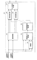
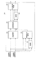
図1は、本発明の実施の形態1に係る微調AFC回路100の構成を示すブロック図である。微調AFC回路100は、遅延器101と、周波数オフセット推定器102と、遅延制御器103と、周波数補正値算出器104と、周波数補正器105と、周波数補正器106、チャネル推定用平均器107と、から主に構成される。
(Embodiment 1)
FIG. 1 is a block diagram showing a configuration of fine
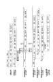
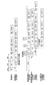
実施の形態1において採用する無線フレームフォーマットは、本実施の形態の特徴を明確にするため、従来の場合と同一とする。図2は、本実施の形態に係る微調AFC回路100の各部で処理される信号のタイミング図である。
The radio frame format employed in the first embodiment is the same as the conventional case in order to clarify the features of the present embodiment. FIG. 2 is a timing chart of signals processed in each unit of the fine
微調AFC回路100は、実数成分Iおよび虚数成分Qを有する受信信号を入力する。受信信号は、遅延器101と、周波数オフセット推定器102と、遅延制御器103とに入力される。
The fine
遅延器101は、受信信号を、先行既知シンボルL♯1のシンボル長に相当する64T遅延して、周波数オフセット推定器102に出力する。
周波数オフセット推定器102は、受信信号と、遅延器101からの受信信号を64T遅延させた信号とで自己相関演算を行い、自己相関結果のI成分(ΔI’)及び(ΔQ’)を積分した値から、周波数オフセット推定を行う。具体的には、周波数オフセット推定器102は、内蔵したCORDIC(Coordinate Rotation Digital Computer)回路等を用いてATAN(ΔQ’/ΔI’)を算出する。算出されたATANは64T分の周波数オフセットω(64)をあらわすので、周波数オフセット推定器102は、算出した周波数オフセットω(64)を1/64することにより1T当りの周波数オフセット、すなわち回転角ω(1)を推定する。このように、受信信号の受信後160T(32T+64T+64T)までに、周波数オフセット推定が完了する。この結果、周波数オフセット推定器602は、基準である1サンプルクロックに応じた回転角ω(1)を周波数補正値算出器104に出力する。周波数補正値算出器104は、このω(1)を受けてサンプルクロックの任意のタイミングtにおける周波数補正値である回転角ω(t)を出力する準備が整う。
The
遅延制御器103は、遅延器101と同時に遅延動作を開始し、先行既知シンボルL♯1のシンボル長64Tの時間差を有する受信信号の144T遅延信号および80T遅延信号の2つの信号を得、それぞれを周波数補正器105および周波数補正器106に出力する。このように、遅延制御器103の両出力に64T(144T−80T)の時間差を設けるのは、既知シンボルL♯1およびL♯2についての周波数補正器105および周波数補正器106に対する出力タイミングを一致させるためである。また、遅延制御器103が受信信号を144T遅延するのは、先頭のGI(その長さ32T)の中央タイミングから周波数補正器105の補正動作を開始し、続いて先行既知シンボルL♯1に対応する信号の周波数補正を行うためである。
The
周波数補正値算出器104は、補正開始後サンプルクロック毎に応じた回転角ω(t)を周波数補正器105および周波数補正器106に出力する。具体的には、周波数補正値算出器104は、遅延制御器103の出力信号の補正開始タイミング以降、回転角ω(1)、ω(2)、ω(3)・・・を周波数補正器105に順次出力し、周波数補正器106にはω(64)、ω(65)、ω(66)・・・を出力する。
The frequency
これによって、周波数補正器105は、ω(1)ないしω(16)によってGI相当部分が周波数補正し、ω(17)ないしω(80)によって先行既知シンボルL♯1を周波数補正する。また、周波数補正器106は、ω(65)ないしω(80)で先行既知シンボルL♯1の後16Tサイクルクロック相当部の周波数補正をし、ω(81)ないしω(144)によって後行既知シンボルL♯2を周波数補正する。これによって、周波数補正器105および周波数補正器106は、それぞれ先行既知シンボルL♯1および後行既知シンボルL♯2をサンプルクロック毎に並列して周波数補正し、かつ同じタイミングで周波数補正を終了する。周波数補正器105および周波数補正器106は、周波数補正をした信号を、チャネル推定用平均器107に出力する。
As a result, the
チャネル推定用平均器107は、サンプルクロック毎に両入力を加算後平均化しチャネル推定を行う。
The
以下、図2のタイミング図に基づき、微調AFC回路100の動作を説明する。
The operation of the fine
まず遅延器101は、受信信号を64T遅延し、両既知シンボルL♯1とL♯2を同じタイミングで周波数オフセット推定器102に入力する。これによって、周波数オフセット推定器102は、ロングトレイニングシンボルの両既知シンボルL♯1とL♯2の入力が終了するタイミングには、周波数オフセット推定を終了する。周波数オフセット推定を終了すると直ちに、周波数オフセット推定器102は、周波数補正値算出器104に、1サイクルクロックの回転角ω(1)を出力する。これによって、周波数補正値算出器104は、先行既知シンボルL♯1に対して、回転角ω(1)、ω(2)、ω(3)・・・を順次出力する準備が整い、また後行既知シンボルL♯2に対して、ω(65)、ω(66)・・・を順次出力する準備が整う。これによって、チャネル推定のための補正が開始可能となる。
First,
遅延制御器103は、遅延器101と同時に遅延動作を開始し、受信信号を144Tおよび80T遅延する。遅延制御器103は、144T遅延した信号を周波数補正器105に出力し、受信信号を80遅延した信号を周波数補正器106に出力する。これによって、周波数補正器105および周波数補正器106は、先行既知シンボルL♯1および後行既知シンボルL♯2を同時並行的に周波数補正することができる。
The
周波数補正器105は、遅延制御器103から先行既知シンボルL♯1が一方側を入力しているタイミングに、他方側に、周波数補正値算出器104からω(1)、ω(2)、ω(3)・・・ω(16)、ω(17)・・・ω(t)・・・ω(80)・・・と各サンプルクロックにおける回転角ω(t)を、順次入力する。これによって、周波数補正器105は、ロングトレイニングシンボルの先行既知シンボルL♯1について、サンプルクロック毎に周波数補正を行う。
The
同時に、周波数補正器106は、遅延制御器103から後行既知シンボルL♯2を一方側に入力しているタイミングに、他方側に、周波数補正値算出器104からω(65)、ω(66)・・・ω(81)・・・ω(t)・・・ω(144)・・・と回転角ω(t)を、順次入力する。これによって、周波数補正器106は、後行既知シンボルL♯2について、サンプルクロック毎に周波数補正を行う。
At the same time, the
このようにして、周波数補正器105および周波数補正器106での周波数補正は並列して行われ、かつ同じタイミングに終了する。
In this way, frequency correction in the
次に、チャネル推定用平均器107は、周波数補正器105および周波数補正器106の出力を入力し、両出力を加算後平均化して、平均値を出力する。チャネル推定用平均器107は、周波数補正器105および周波数補正器106の周波数補正が終了するタイミングには、平均値をチャネル推定データとして出力する。以下チャネル推定用平均器107は、周波数補正されたGIに相当する信号、データ(DATA)に相当する信号を順次出力する。
Next, the
以上のように、本実施の形態によれば、周波数オフセット推定動作中に、周波数補正のための受信信号の遅延動作を並行して行うようにしたので、従来に比べて、処理の時間的効率が上昇し、応答速度の速いAFC回路を実現することができる。特に、受信性能向上のためロングトレイニングシンボルのL♯1およびL♯2のシンボル長が長く設定され、周波数補正のための処理時間が大きくなる場合に、本実施の形態の効果は大きい。
As described above, according to the present embodiment, the received signal delay operation for frequency correction is performed in parallel during the frequency offset estimation operation. As a result, an AFC circuit with a high response speed can be realized. In particular, the effect of the present embodiment is significant when the long training
(実施の形態2)
実施の形態1においては、受信信号の無線フレームフォーマットは、ロングトレイニングシンボル部分が二つの既知シンボルL♯1、L♯2であるものについて説明した。これは、一つのアンテナで受信信号を受信する場合に該当する。しかし、本発明は、これに限られず、複数のアンテナを用いて受信するSDM(Space Division Multiplexing)伝送方式やSTC(Space-Time Coding)伝送方式においても採用できる。そのためロングトレイニングシンボル部分に既知シンボルが4個以上設けられる場合においても、適用可能である。以下、SDM方式やSTC方式で受信する本発明の実施の形態2について説明する。
(Embodiment 2)
In the first embodiment, the radio frame format of the received signal has been described in which the long training symbol part is two known
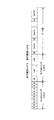
図3は、本発明の実施の形態2に係る微調AFC回路300の構成を示すブロック図である。図3において、図1と共通する構成については、図1と同一の参照符号を付す。図3において、遅延制御器303は、受信信号を無線フレームフォーマットに従い遅延する。周波数補正値算出器304は、遅延制御器303の出力タイミングに応じた回転角ω(t)を周波数補正器105および周波数補正器106に出力する。
FIG. 3 is a block diagram showing a configuration of fine
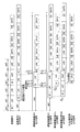
図4は、本発明の実施の形態2に係る微調AFC回路の各部で処理される信号のタイミング図である。図4において、図2と同じ部分については説明を省略する。図4の受信信号で示すように、本実施の形態においては、無線フレームファーマットは、先頭のGI(32T)、既知シンボルL♯1(64T)、既知シンボルL♯2(64T)、2番目のGI(32T)、既知シンボルL♯3(64T)、既知シンボルL♯4(64T)でロングトレイニング部が構成され、以下実施の形態1の場合と同様16TのGIとデータ(DATA)部が順次割り当てられる。 FIG. 4 is a timing diagram of signals processed in each part of the fine adjustment AFC circuit according to the second embodiment of the present invention. 4, description of the same parts as those in FIG. 2 is omitted. As shown by the received signal in FIG. 4, in the present embodiment, the radio frame format is the first GI (32T), known symbol L # 1 (64T), known symbol L # 2 (64T), second GI (32T), known symbol L # 3 (64T), and known symbol L # 4 (64T) constitute a long training section, and a 16T GI and data (DATA) section as in the first embodiment. Are assigned sequentially.
実施の形態2に係る微調AFC回路300は、実施の形態1の微調AFC回路100同様、先頭のGIの中央タイミングから周波数補正を行うが、既知シンボルL♯3と既知シンボルL♯4に対応する信号を周波数補正するため、第2のGIの中央タイミングの回転角ω(161)と、既知シンボルL♯3の16T前の回転角ω(225)のタイミングを利用する。
Like the fine
以下、図3および図4に従い微調AFC回路300の動作を説明する。
Hereinafter, the operation of the fine
実施の形態1と同様、周波数オフセット推定器102は、受信信号および遅延器101からの遅延信号を受けて周波数オフセット推定を行い、1サイクルクロックの回転角ω(1)を周波数補正値算出器304に出力する。これによって周波数補正値算出器304は、既知シンボルL♯1および既知シンボルL♯4に対する、回転角ω(1)、ω(2)、ω(3)・・・ω(17)・・・ω(80)、ω(225)・・・を順次出力する準備が整い、また既知シンボルL♯2および既知シンボルL♯3に対する、回転角ω(65)、ω(66)・・・ω(144)、ω(161)・・・を順次出力する準備が整う。
Similar to the first embodiment, the frequency offset
遅延制御器303は、既知シンボルL♯1および既知シンボルL♯2に対応する信号によりチャネル推定を行うため、遅延動作の最初において、実施の形態1における遅延制御器103と同様、周波数補正器105に受信信号を144T遅延した信号を出力し、周波数補正器106には80T遅延した信号を出力する。
Since
次に周波数補正器105および周波数補正器106に対しては、実施の形態1の場合と同様、サンプルクロックに応じた回転角ω(t)が入力され、周波数補正される。周波数補正された信号は、周波数補正器105および周波数補正器106からチャネル推定用平均器107に出力され、チャネル推定用平均器107は、既知シンボルL♯1および既知シンボルL♯2に対応するチャネル推定データを出力する。
Next, as in the case of the first embodiment, the rotation angle ω (t) corresponding to the sample clock is input to the
以上は、実施の形態1の場合と同様である。すなわち、周波数オフセット推定器102によるオフセット推定動作と並列して、遅延制御器303の遅延動作を開始するので、微調AFC回路300の応答速度を速くすることができる。
The above is the same as in the first embodiment. That is, since the delay operation of the
次に、遅延制御器303は、144T遅延した受信信号における既知シンボルL♯1の出力を完了すると、遅延動作を切り替え、受信信号の既知シンボル♯4の16T前からに相当する信号を周波数補正器105に出力する。また、遅延制御器303は、80T遅延した受信信号における既知シンボルL♯2の出力を完了すると、遅延動作を切り替え、受信信号の2番目のGIの中央タイミングからに相当する信号を周波数補正器106に出力する。
Next, when the output of the known
この遅延制御器303の前記遅延動作切り替えに同期して、周波数補正値算出器304は、回転角ω(225)、ω(226)・・・を周波数補正器105に順次出力し、周波数補正器106には回転角ω(161)、ω(162)・・・を順次出力する。
In synchronization with the delay operation switching of the
これによって、周波数補正器105は既知シンボルL♯4に対応する信号を周波数補正してチャネル推定用平均器107に出力する。同時に周波数補正器106は、既知シンボルL♯3に対応する信号を周波数補正してチャネル推定用平均器107に出力する。
Thus,
チャネル推定用平均器107は、周波数補正器105および周波数補正器106の出力を加算後平均化し、GIに対応する信号に続いて、既知シンボルL♯3およびL♯4に基づくチャネル推定データを出力する。以下、チャネル推定用平均器107は、周波数補正されたGI相当信号、データ(DATA)信号を順次出力する。
以上のように本実施の形態によれば、既知シンボルL♯1およびL♯2に基づくチャネル推定データ算出すると、遅延制御器303の遅延動作切り替えにより直ちに、既知シンボルL♯3およびL♯4に基づくチャネル推定データの算出を行うので、AFC回路の処理速度を高めることができる。すなわち、ロングトレイニング部にL♯1およびL♯2の第1組とL♯1およびL♯2の第2組の既知シンボルを設定する場合も、各既知シンボルに関する処理が直列的に行われるとはないので、AFC回路の応答速度を高くすることができる。このように本実施の形態に係るAFC回路は、既知シンボルを4個以上設ける場合も応答速度を高くできるので、SDM方式やSTC方式による無線通信を高速化することができる。
As described above, according to the present embodiment, when channel estimation data is calculated based on known
なお上記各実施の形態では、チャネル推定用平均器107は、周波数補正器105および周波数補正器106の出力をベクトル的な単純加算する例で説明したが、本発明はこれに限られず周波数補正器105および周波数補正器106の出力を複数段入力してそれらの加重平均をとり、加重平均値をチャネル推定データとするようにしてもよい。
In each of the above-described embodiments, the
本発明のAFC回路は、高速にAFCを行うことができるので、無線LANやETC、デジタル地上波放送などで採用されている変調方式の高速化に有用である。特に、OFDM変調方式による無線LANの規格としては、HiSWANa、IEEE802.11aが代表としてあげられるが、本発明はこれらの規格を実装する際にも有用である。 Since the AFC circuit of the present invention can perform AFC at high speed, it is useful for increasing the speed of a modulation method employed in wireless LAN, ETC, digital terrestrial broadcasting, and the like. In particular, HiSWANa and IEEE802.11a are representative examples of wireless LAN standards based on the OFDM modulation method, but the present invention is also useful when implementing these standards.
100 微調AFC回路
101 遅延器
102 周波数オフセット推定器
103、303 遅延制御器
104、304 周波数補正値算出器
105、106 周波数補正器
107 チャネル推定用平均器
DESCRIPTION OF
Claims (3)
推定された周波数オフセットに基づき、前記受信信号のサンプルクロック毎の周波数補正値を算出する周波数補正値算出手段と、
前記周波数オフセット推定手段が周波数オフセットを推定する期間に前記受信信号の遅延動作を開始し、前記既知シンボルの長さに相当する時間差を有する第1の遅延信号および第2の遅延信号を出力する遅延制御手段と、
前記第1の遅延信号を、前記周波数補正値算出手段の周波数補正値で周波数補正する第1の周波数補正手段と、
前記第2の遅延信号を、前記周波数補正値算出手段の周波数補正値で周波数補正する第2の周波数補正手段と、
を具備した自動周波数制御回路。 Frequency offset estimation means for estimating the frequency offset of the received signal based on the autocorrelation calculation result using the preceding and succeeding known symbols provided in the received signal;
A frequency correction value calculating means for calculating a frequency correction value for each sample clock of the received signal based on the estimated frequency offset;
A delay for starting a delay operation of the received signal during a period in which the frequency offset estimation means estimates a frequency offset, and outputting a first delay signal and a second delay signal having a time difference corresponding to the length of the known symbol Control means;
First frequency correction means for correcting the frequency of the first delayed signal with the frequency correction value of the frequency correction value calculation means;
Second frequency correction means for correcting the frequency of the second delayed signal with the frequency correction value of the frequency correction value calculation means;
An automatic frequency control circuit comprising:
推定された周波数オフセットに基づき、前記受信信号のサンプルクロック毎の周波数補正値を算出する周波数補正値算出ステップと、
前記周波数オフセット推定ステップで周波数オフセットを推定する期間に前記受信信号の遅延動作を開始し、前記既知シンボルの長さに相当する時間差を有する第1の遅延信号および第2の遅延信号を出力する遅延制御ステップと、
前記第1の遅延信号を、前記周波数補正値算出ステップで求めた周波数補正値で周波数補正する第1の周波数補正ステップと、
前記第2の遅延信号を、前記周波数補正値算出ステップで求めた周波数補正値で周波数補正する第2の周波数補正ステップと、
を具備した自動周波数制御回路の制御方法。 A frequency offset estimating step for estimating a frequency offset of the received signal based on an autocorrelation calculation using a preceding and succeeding known symbols provided in the received signal;
A frequency correction value calculating step of calculating a frequency correction value for each sample clock of the received signal based on the estimated frequency offset;
A delay for starting a delay operation of the received signal during a period in which the frequency offset is estimated in the frequency offset estimating step, and outputting a first delay signal and a second delay signal having a time difference corresponding to the length of the known symbol Control steps;
A first frequency correction step of correcting the frequency of the first delay signal with the frequency correction value obtained in the frequency correction value calculation step;
A second frequency correction step of correcting the frequency of the second delayed signal with the frequency correction value obtained in the frequency correction value calculation step;
A method for controlling an automatic frequency control circuit comprising:
Priority Applications (1)
| Application Number | Priority Date | Filing Date | Title |
|---|---|---|---|
| JP2005361027A JP2007166327A (en) | 2005-12-14 | 2005-12-14 | Automatic frequency control circuit and control method thereof |
Applications Claiming Priority (1)
| Application Number | Priority Date | Filing Date | Title |
|---|---|---|---|
| JP2005361027A JP2007166327A (en) | 2005-12-14 | 2005-12-14 | Automatic frequency control circuit and control method thereof |
Publications (1)
| Publication Number | Publication Date |
|---|---|
| JP2007166327A true JP2007166327A (en) | 2007-06-28 |
Family
ID=38248699
Family Applications (1)
| Application Number | Title | Priority Date | Filing Date |
|---|---|---|---|
| JP2005361027A Pending JP2007166327A (en) | 2005-12-14 | 2005-12-14 | Automatic frequency control circuit and control method thereof |
Country Status (1)
| Country | Link |
|---|---|
| JP (1) | JP2007166327A (en) |
Cited By (1)
| Publication number | Priority date | Publication date | Assignee | Title |
|---|---|---|---|---|
| JP2009055309A (en) * | 2007-08-27 | 2009-03-12 | Oki Electric Ind Co Ltd | Offset estimation device |
-
2005
- 2005-12-14 JP JP2005361027A patent/JP2007166327A/en active Pending
Cited By (1)
| Publication number | Priority date | Publication date | Assignee | Title |
|---|---|---|---|---|
| JP2009055309A (en) * | 2007-08-27 | 2009-03-12 | Oki Electric Ind Co Ltd | Offset estimation device |
Similar Documents
| Publication | Publication Date | Title |
|---|---|---|
| US20060176802A1 (en) | Apparatus and method for compensating for frequency offset in wireless communication system | |
| KR101656083B1 (en) | Apparatus and method for obtaining reception synchronization in wireless communication system | |
| KR20050008431A (en) | Digital broadcasting transmission/reception capable of improving a receiving performance and a method signal processing thereof | |
| US7577216B2 (en) | Guard interval and FFT mode detector in DVB-T receiver | |
| JPH11346206A (en) | Digital broadcast receiver | |
| JP2001136149A (en) | OFDM receiver for wireless packet communication | |
| US20100046359A1 (en) | Wireless Terminal, Base Station and Channel Characteristic Estimating Method | |
| US9553752B1 (en) | Method and apparatus for frequency offset detection in OFDM systems with frequency reuse | |
| EP2884682B1 (en) | Receiver, method for estimating frequency response of transmission path by receiver | |
| US8422593B2 (en) | Parallel automatic frequency offset estimation method and apparatus | |
| JP2008263426A (en) | Frequency correction circuit and frequency correction method | |
| JP2007166327A (en) | Automatic frequency control circuit and control method thereof | |
| JP2002152173A (en) | Ofdm system receiver | |
| JP4056238B2 (en) | Digital signal receiver | |
| JP4448454B2 (en) | Symbol synchronization circuit | |
| CN111294917B (en) | Method, device, storage medium and user equipment for estimating timing deviation based on PDCCH | |
| JP3636944B2 (en) | OFDM demodulator | |
| CN100571120C (en) | A Frame Synchronization Method in Digital Communication | |
| JP4326015B2 (en) | Receiving apparatus and receiving method | |
| US7920660B2 (en) | Method and arrangement for removing DC offset from data symbols | |
| JP4255908B2 (en) | Multi-carrier signal demodulation circuit and multi-carrier signal demodulation method | |
| CN102025670B (en) | Residual carrier frequency offset tracking method applied to mobile multimedia broadcasting system | |
| JP2006295766A (en) | Nonlinear strain equalization system | |
| JP2002152174A (en) | Ofdm system receiver | |
| JP2008211365A (en) | Demodulator and frame synchronization method |