JP2007166314A - Microphone device, microphone assembly tray, reversing plate, and method of manufacturing microphone device - Google Patents
Microphone device, microphone assembly tray, reversing plate, and method of manufacturing microphone device Download PDFInfo
- Publication number
- JP2007166314A JP2007166314A JP2005360761A JP2005360761A JP2007166314A JP 2007166314 A JP2007166314 A JP 2007166314A JP 2005360761 A JP2005360761 A JP 2005360761A JP 2005360761 A JP2005360761 A JP 2005360761A JP 2007166314 A JP2007166314 A JP 2007166314A
- Authority
- JP
- Japan
- Prior art keywords
- holder
- microphone
- elastic body
- tray
- coil spring
- Prior art date
- Legal status (The legal status is an assumption and is not a legal conclusion. Google has not performed a legal analysis and makes no representation as to the accuracy of the status listed.)
- Granted
Links
Images

Landscapes
- Details Of Audible-Bandwidth Transducers (AREA)
Abstract
【課題】人の手を介在することなくコイルバネの取り付けを行うことができ、しかもマイクロホンの小型化を図っても高い位置精度で取り付けることができるマイクロホンおよびマイクロホンの製造方法を提供する。
【解決手段】本発明のマイクロホン装置は、音信号を電気信号に変換して出力するマイクロホンユニットと、前記マイクロホンユニットの電極を外部と接続する導電性の弾性体と、硬質材料から成り、前記弾性体を保持する弾性体挿入孔と、前記マイクロホンユニットが嵌めこまれる外周縁部と、を有する第1ホルダと、前記外周縁部に前記マイクロホンユニットが差し込まれた状態の前記第1ホルダを収容する第2ホルダと、を備え、前記外周縁部は、前記弾性体を収容する凹部を有するマイクロホン組立て用トレイ上に複数設けられた溝部に嵌めこまれる形状である。
【選択図】図1A microphone and a method of manufacturing a microphone that can be attached with high positional accuracy even when a coil spring can be miniaturized and the coil spring can be attached without involving a human hand.
A microphone device according to the present invention includes a microphone unit that converts a sound signal into an electric signal and outputs the signal, a conductive elastic body that connects an electrode of the microphone unit to the outside, and a hard material. A first holder having an elastic body insertion hole for holding a body and an outer peripheral edge portion into which the microphone unit is fitted, and the first holder in a state where the microphone unit is inserted into the outer peripheral edge portion are accommodated. A second holder, wherein the outer peripheral edge portion is fitted into a plurality of groove portions provided on a microphone assembly tray having a recess for accommodating the elastic body.
[Selection] Figure 1
Description
本発明は、携帯電話機等に使用されるマイクロホン装置、そのマイクロホン装置の製造方法、そのマイクロホン装置を製造する際に用いるマイクロホン組立て用トレイ、反転用プレートに関する。 The present invention relates to a microphone device used for a mobile phone, a method for manufacturing the microphone device, a microphone assembly tray and a reversing plate used when manufacturing the microphone device.
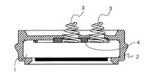
従来、この種のマイクロホンとして、例えば、図16に示すようなものがある(特許文献1参照)。この図に示すマイクロホンは、マイクロホンユニット1と、このマイクロホンユニット1を収容するホルダ2と、マイクロホンユニット1の2つの電極と外部の基板(図示略)上のパターンとを電気的に接続する2個のコイルバネ3と、ホルダ2に収容され2個のコイルバネ3を支持するコイルバネ支持部4とから構成されている。
Conventionally, as this type of microphone, for example, there is one shown in FIG. 16 (see Patent Document 1). The microphone shown in this figure includes two units for electrically connecting a
ホルダ2はゴム等の軟質材料により構成されている。コイルバネ支持部4は、バネの保持強度を十分なものとするため、プラスチックやPP等の硬質材料により構成されている。コイルバネ支持部4には2個のコイルバネ3を支持するためのコイルバネ支持穴が形成されており、ホルダ2には2個のコイルバネ3を通過させるコイルバネ挿入孔が形成されている。
The
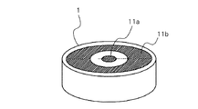
マイクロホンユニット1は、図17の斜視図に示すように、その上面に電極パターン11a、11bが形成されており、これらの電極パターン11a、11bに2個のコイルバネ3の一端が電気的に接続される。この従来のマイクロホンは、コイルバネ支持部4に2個のコイルバネ3を装着した状態でホルダ2内にマイクロホンユニット1を挿入する手順で製造される。
As shown in the perspective view of FIG. 17, the
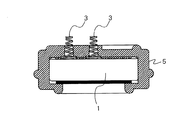
また、従来の他のマイクロホンとして、図18の断面図に示すようなものもある。この図に示すマイクロホンは、マイクロホンユニット1と、このマイクロホンユニット1を収容するゴム等の軟質部材からなるホルダ5と、マイクロホンユニット1の2つの電極と外部の基板上のパターン(図示略)とを電気的に接続する2個のコイルバネ3とから構成されている。
Another conventional microphone is shown in the cross-sectional view of FIG. The microphone shown in this figure includes a
ホルダ5には2個のコイルバネ3を通過させるコイルバネ挿入孔が形成されている。この従来のマイクロホンは、ホルダ5の開口部を上向きにした状態でホルダ5の各コイルバネ挿入孔のコイルバネ3を挿入した後、マイクロホンユニット1を挿入する手順で製造される。
上述のようなマイクロホンは、マイクロホンの小型化に伴ってマイクロホンユニットの電極パターンの面積が小さくなるとともにコイルバネも小型化する必要が生じている。しかしながら、軟質部材からなるホルダではコイルバネを挿入する孔の径寸法及び位置精度に問題があるため、コイルバネを一個ずつ人の手で挿入せざるを得ない。よって、従来のマイクロホンの製造方法では、この工程に多くの時間を要し作業効率が良くない。また、コイルバネが小さくなれば、必然的に扱い難くなることもあってその取り付けに時間がかかり作業効率が悪化してしまう。 In the microphone as described above, it is necessary to reduce the area of the electrode pattern of the microphone unit and to reduce the size of the coil spring as the microphone is downsized. However, since the holder made of a soft member has a problem in the diameter and position accuracy of the hole into which the coil spring is inserted, the coil spring must be manually inserted one by one. Therefore, in the conventional method for manufacturing a microphone, this process takes a lot of time and the working efficiency is not good. In addition, if the coil spring is small, it may be inevitably difficult to handle, and it takes a long time to attach the coil spring, and the working efficiency deteriorates.
また、コイルバネを手で触るのでバネの品質を一定に保つことが困難である。 Further, since the coil spring is touched by hand, it is difficult to keep the quality of the spring constant.
また、上述のマイクロホンのホルダはマイクロホンユニットを包み込む構造としている。例えば、図16に示すマイクロホン1では、ホルダ2内へのマイクロホンユニット1の挿入の際に、ホルダ2の開口部を広げてマイクロホンユニット1を挿入する。同様に図17に示すマイクロホンでも、マイクロホンユニットの挿入時にはホルダの口を広げる必要がある。この工程において、コイルバネが固定されていない状態でマイクロホンユニットを挿入するので、コイルバネが暴れ易く、製造工程の自動化が困難である。
Further, the above-described microphone holder is configured to enclose the microphone unit. For example, in the
本発明は係る事情に鑑みてなされたものであり、従来、個別にコイルバネを挿入する工程を一括して行って作業効率を向上させることができるマイクロホンの製造方法を提供することを目的とする。 The present invention has been made in view of such circumstances, and an object of the present invention is to provide a method of manufacturing a microphone that can improve work efficiency by collectively performing a process of inserting coil springs individually.
本発明のマイクロホン装置の製造方法は、音信号を電気信号に変換して出力するマイクロホンユニットと、前記マイクロホンユニットの電極を外部と接続する導電性の弾性体と、硬質材料から成り、前記弾性体を保持する弾性体挿入孔と、前記マイクロホンユニットが嵌めこまれるとともに、マイクロホン組立て用トレイ上に複数設けられた溝部に嵌めこまれる形状である外周縁部と、を備える第1のホルダと、前記外周縁部に前記マイクロホンユニットが差し込まれた状態の前記第1ホルダを収容する第2ホルダと、を備えるマイクロホン装置を、前記第1ホルダが嵌め込まれる第1ホルダ挿嵌部を複数有し、前記第1ホルダ挿嵌部が、前記第1ホルダの外周縁部と対応する溝部と、前記弾性体を収容する凹部と、を備えるマイクロホン組立て用トレイと、反転した前記第1ホルダを保持する第1ホルダ収容部を複数有し、前記第1ホルダ収容部が、前記第1ホルダの前記弾性体挿入孔から前記弾性体が突き出す部分を逃がす孔又は凹部を備えている反転プレートと、を用いて組み立てるマイクロホン装置の製造方法において、前記トレイの凹部に前記弾性体を収容する弾性体収容工程と、前記トレイの溝部に前記第1ホルダの外周縁部を嵌め込む第1ホルダ嵌め込み工程と、前記トレイの第1ホルダ挿嵌部と前記反転プレートの第1ホルダ収容部とが対応して重なるように、前記トレイと前記反転プレートとを重ねて上下反転する上下反転工程と、を有する。 The method of manufacturing a microphone device according to the present invention includes a microphone unit that converts a sound signal into an electric signal and outputs it, a conductive elastic body that connects an electrode of the microphone unit to the outside, and a hard material, and the elastic body A first holder comprising: an elastic body insertion hole that holds the outer periphery of the microphone assembly; and an outer peripheral edge portion that is fitted into a plurality of groove portions provided on the microphone assembly tray; A microphone device comprising: a second holder that accommodates the first holder in a state where the microphone unit is inserted into an outer peripheral edge portion; and a plurality of first holder insertion portions into which the first holder is fitted, A microphone set, wherein the first holder insertion portion includes a groove portion corresponding to the outer peripheral edge portion of the first holder, and a concave portion for accommodating the elastic body. A plurality of first holder accommodating portions that hold the inverted first holder, and the first holder accommodating portion has a portion where the elastic body protrudes from the elastic body insertion hole of the first holder. In a method of manufacturing a microphone device that is assembled using a reversing plate having a hole or a recess for escaping, an elastic body housing step of housing the elastic body in the recess of the tray, and a groove portion of the tray The tray and the reversing plate are overlapped so that the first holder fitting step for fitting the outer peripheral edge portion and the first holder insertion portion of the tray and the first holder housing portion of the reversing plate overlap with each other. And an upside down process for turning upside down.
この製造方法により、弾性体を保持する第1ホルダに硬質材料を使用することで、コイルバネ等の弾性体を保持する弾性体挿入孔等の寸法精度を出すことが可能となる。また、マイクロホン組立て用トレイに弾性体を収容して、トレイとを反転プレートとを重ね合わせて上下反転することで、トレイに嵌め込まれて保持されている第1ホルダの弾性体挿入孔に弾性体が落下して挿入されるので、弾性体に触れることなく、トレイに嵌め込まれた各々の第1ホルダに一括して弾性体を挿入することが可能となる。これは、弾性体が小さくなってもトレイの弾性体を収容する凹部の穴の大きさを変えることで対応できる。これにより、品質の向上及び生産効率を上げることが可能となる。 With this manufacturing method, it is possible to obtain dimensional accuracy of an elastic body insertion hole or the like for holding an elastic body such as a coil spring by using a hard material for the first holder that holds the elastic body. In addition, the elastic body is accommodated in the microphone assembling tray, and the tray is turned upside down by overlapping the reversing plate, so that the elastic body is inserted into the elastic body insertion hole of the first holder that is fitted and held in the tray. Is dropped and inserted, it is possible to insert the elastic body into each first holder fitted in the tray without touching the elastic body. This can be dealt with by changing the size of the hole of the recess for accommodating the elastic body of the tray even if the elastic body becomes small. This makes it possible to improve quality and increase production efficiency.
また、本発明のマイクロホン装置の製造方法は、前記上下反転工程において、前記トレイと前記プレートとが反転の際にたわまないように押え込みプレートによって押さえつけながら反転させ、反転後に振動を加えてから前記反転プレートを外す工程を有するものである。 Further, in the microphone device manufacturing method of the present invention, in the upside down process, the tray and the plate are reversed while being pressed by the pressing plate so that the tray and the plate do not bend during the reversal, and vibration is applied after the reversal. And a step of removing the reversing plate.
この工程によれば、上下反転工程において、前記トレイと前記プレートとが押さえつけられているので、上下反転の際に前記トレイと前記プレートとの間に隙間が発生して弾性体が飛び出すのを防止することができる。また、反転後に前記プレートの外周部のバネに振動を与えることで前記トレイに嵌め込まれた第1ホルダが外れやすくなる。 According to this process, since the tray and the plate are pressed in the upside down process, a gap is generated between the tray and the plate during the upside down process to prevent the elastic body from popping out. can do. In addition, the first holder fitted in the tray can be easily detached by applying vibration to the spring on the outer peripheral portion of the plate after the reversal.
また、本発明のマイクロホン装置の製造方法は、前記上下反転工程の後、前記反転プレートの第1ホルダ収容部に保持された前記1ホルダに前記マイクロホンユニットを差し込むマイクロホンユニット差込工程を有するものである。 The microphone device manufacturing method of the present invention includes a microphone unit insertion step of inserting the microphone unit into the one holder held in the first holder housing portion of the inversion plate after the upside down step. is there.
この工程によれば、前記上下反転工程の後、反転プレートには、弾性体が挿入されている第1ホルダが、第1ホルダ収容部に保持・固定された状態であるので、安定・確実にマイクロホンユニットを差し込むことができる。 According to this process, after the upside down process, since the first holder in which the elastic body is inserted is held and fixed to the first holder housing portion on the reversing plate, it is stable and reliable. A microphone unit can be inserted.
また、本発明のマイクロホン装置の製造方法は、前記反転プレートが、前記マイクロホンユニットを装着するための治具を固定する溝部を有しており、前記マイクロホンユニット差込工程において、前記治具を用いて前記マイクロホンユニットの差し込みを行うものである。 In the microphone device manufacturing method of the present invention, the inversion plate has a groove for fixing a jig for mounting the microphone unit, and the jig is used in the microphone unit insertion step. The microphone unit is inserted.
この工程によれば、反転プレートに設けられた溝部に治具の一部を差し込んで、治具を用いてマイクロホンユニットの差し込みを行うので、安定かつ効率的に差し込み工程を行うことができる。 According to this step, since a part of the jig is inserted into the groove provided in the reversing plate and the microphone unit is inserted using the jig, the insertion step can be performed stably and efficiently.
また、本発明のマイクロホン装置は、音信号を電気信号に変換して出力するマイクロホンユニットと、前記マイクロホンユニットの電極を外部と接続する導電性の弾性体と、硬質材料から成り、前記弾性体を保持する弾性体挿入孔と、前記マイクロホンユニットが嵌めこまれる外周縁部と、を有する第1ホルダと、前記外周縁部に前記マイクロホンユニットが差し込まれた状態の前記第1ホルダを収容する第2ホルダと、を備え、前記外周縁部は、前記弾性体を収容する凹部を有するマイクロホン組立て用トレイ上に複数設けられた溝部に嵌めこまれる形状である。 Further, the microphone device of the present invention comprises a microphone unit that converts a sound signal into an electric signal and outputs it, a conductive elastic body that connects an electrode of the microphone unit to the outside, and a hard material. A first holder having an elastic body insertion hole to hold, an outer peripheral edge portion into which the microphone unit is fitted, and a second holder for receiving the first holder in a state where the microphone unit is inserted into the outer peripheral edge portion. A holder, and the outer peripheral edge has a shape fitted into a plurality of grooves provided on a microphone assembling tray having a recess for accommodating the elastic body.
この構成により、弾性体を保持する第1ホルダに硬質材料を使用されているので、コイルバネ等の弾性体を保持する弾性体挿入孔等の寸法精度を出すことが可能となり、小型化も可能となる。また、第1ホルダに弾性体を挿入する組立て工程を、人手ではなく、組み立て用のトレイを用いて一括して行うことができるので、生産効率が向上する。 With this configuration, since the hard material is used for the first holder that holds the elastic body, it is possible to obtain a dimensional accuracy of the elastic body insertion hole that holds the elastic body such as a coil spring, and the size can be reduced. Become. In addition, the assembly process for inserting the elastic body into the first holder can be performed collectively using an assembly tray instead of manual operation, so that the production efficiency is improved.
また、本発明のマイクロホン装置の前記第1ホルダは、前記外周縁部が嵌めこまれる位置を決定する位置決め部を備えている。 Further, the first holder of the microphone device of the present invention includes a positioning portion that determines a position where the outer peripheral edge portion is fitted.
この構成により、マイクロホン組立て用トレイに第1ホルダを嵌め込むときの位置決めの精度が向上する。 With this configuration, the positioning accuracy when the first holder is fitted into the microphone assembly tray is improved.
また、本発明のマイクロホン装置の前記位置決め部は、前記第1ホルダの底板部に設けられる位置決め孔又は凹部である。 In the microphone device of the present invention, the positioning portion is a positioning hole or a recess provided in the bottom plate portion of the first holder.
この構成により、マイクロホン組立て用トレイの凸部に前記位置決め孔又は凹部を嵌合することで位置決めが行われる。 With this configuration, positioning is performed by fitting the positioning hole or the concave portion to the convex portion of the microphone assembling tray.
また、本発明のマイクロホン装置の前記位置決め孔又は凹部は、テーパ形状である。 Further, the positioning hole or the concave portion of the microphone device of the present invention has a tapered shape.
この構成により、マイクロホン組立て用トレイから第1ホルダを外す際に、適度な振動を与えることで外すことができる。 With this configuration, when removing the first holder from the microphone assembly tray, the first holder can be removed by applying an appropriate vibration.
また、本発明のマイクロホン装置の前記位置決め部は、前記第1ホルダの外周部に設けられる位置決め凸部である。 Further, the positioning part of the microphone device of the present invention is a positioning convex part provided on an outer peripheral part of the first holder.
この構成により、マイクロホン組立て用トレイ上に設けられた溝部の一部を前記位置決め凸部と対応するように拡大して形成することで、位置決めを行うことができる。 With this configuration, positioning can be performed by enlarging and forming a part of the groove provided on the microphone assembly tray so as to correspond to the positioning convex portion.
また、本発明のマイクロホン組立て用トレイは、前記第1ホルダが嵌め込まれる第1ホルダ挿嵌部を複数有し、前記第1ホルダ挿嵌部は、前記第1ホルダの外周縁部と対応する溝部と、前記位置決め孔又は凹部と対応する突起部と、前記弾性体を収容する凹部と、を備える。 The microphone assembly tray of the present invention has a plurality of first holder insertion portions into which the first holder is fitted, and the first holder insertion portion is a groove portion corresponding to an outer peripheral edge portion of the first holder. And a protrusion corresponding to the positioning hole or the recess and a recess for accommodating the elastic body.
この構成により、突起部に第1ホルダが有する位置決め孔又は凹部を合わせることで、精度良く位置決めを行うことができる。また、トレイの前記弾性体を収容する凹部に、まとめて弾性体を収容させて、その後溝部に第1ホルダを嵌め込み反転させることで、一括して第1ホルダに弾性体を挿入することができる。 With this configuration, positioning can be performed with high accuracy by aligning the positioning hole or recess of the first holder with the protrusion. In addition, the elastic body can be collectively inserted into the concave portion for accommodating the elastic body of the tray, and the elastic body can be inserted into the first holder in a lump by subsequently fitting and inverting the first holder in the groove. .
また、本発明のマイクロホン組立て用トレイは、前記第1ホルダが嵌め込まれる第1ホルダ挿嵌部を複数有し、前記第1ホルダ挿嵌部は、前記第1ホルダの外周縁部と対応する溝部と、前記弾性体を収容する凹部と、を備え、前記溝部は、前記第1ホルダの前記位置決め凸部と対応する凹部を備える。 The microphone assembly tray of the present invention has a plurality of first holder insertion portions into which the first holder is fitted, and the first holder insertion portion is a groove portion corresponding to an outer peripheral edge portion of the first holder. And a recess accommodating the elastic body, and the groove includes a recess corresponding to the positioning protrusion of the first holder.
この構成により、トレイの溝部に設けられた凹部に第1ホルダが外周部に有する位置決め凸部を合わせることで、精度良く位置決めを行うことができる。また、トレイの前記弾性体を収容する凹部に、まとめて弾性体を収容させて、その後溝部に第1ホルダを嵌め込み反転させることで、一括して第1ホルダに弾性体を挿入することができる。 With this configuration, positioning can be performed with high accuracy by aligning the positioning protrusions of the outer circumference with the first holder with the recesses provided in the groove of the tray. In addition, the elastic body can be collectively inserted into the concave portion for accommodating the elastic body of the tray, and the elastic body can be inserted into the first holder in a lump by subsequently fitting and inverting the first holder in the groove. .
また、本発明のマイクロホン組立て用トレイは、前記トレイの外周部に、前記トレイを反転させるのに用いる反転用プレートの外周部に設けられた凸部と対応する孔又は凹部を備える。 In the microphone assembly tray of the present invention, a hole or a recess corresponding to a protrusion provided on the outer periphery of the reversing plate used for reversing the tray is provided on the outer periphery of the tray.
この構成により、トレイと反転用プレートとを精度良く重ね合わせることができ、反転後、反転プレートに確実に第1ホルダを収容させることができる。 With this configuration, the tray and the reversing plate can be accurately overlapped, and the first holder can be reliably accommodated in the reversing plate after the reversing.
また、本発明の反転用プレートは、反転した前記第1ホルダを保持する第1ホルダ収容部を複数有し、前記第1ホルダ収容部は、前記第1ホルダの前記弾性体挿入孔から前記弾性体が突き出す部分を逃がす孔又は凹部を有するものでり、プレートの外周部にバネ部を備える。 Further, the reversing plate of the present invention has a plurality of first holder accommodating portions for holding the inverted first holder, and the first holder accommodating portion is elastically inserted from the elastic body insertion hole of the first holder. It has a hole or recess that allows the body to protrude, and has a spring portion on the outer periphery of the plate.
この構成により、弾性体と第1ホルダを収容したトレイと反転プレートを重ね合わせて上下反転させると、反転プレートには、弾性体が挿入された状態の第1ホルダが保持された状態となる。また、重ね合わせたトレイを簡単に外すことができる。このとき、弾性体の第1ホルダから突き出した部分は、前記逃がす孔又は凹部により反転プレートとは接触しないようにされているので、そのままマイクロホンユニットを挿し込むことができる。 With this configuration, when the tray containing the elastic body and the first holder and the reversing plate are overlapped and turned upside down, the reversing plate holds the first holder with the elastic body inserted therein. In addition, the stacked trays can be easily removed. At this time, the portion protruding from the first holder of the elastic body is prevented from coming into contact with the reversing plate by the escape hole or recess, so that the microphone unit can be inserted as it is.
また、本発明の反転用プレートは、前記マイクロホンユニットを装着するための治具を固定する溝部を備える。 The reversing plate of the present invention includes a groove portion for fixing a jig for mounting the microphone unit.
この構成により、第1ホルダにマイクロホンユニットを装着するための治具を確実に固定することができる。 With this configuration, a jig for mounting the microphone unit on the first holder can be securely fixed.
また、本発明の反転用プレートは、前記マイクロホン組立て用トレイの外周部に設けられた孔又は凹部と対応する凸部を備える。 The reversing plate of the present invention includes a convex portion corresponding to a hole or a concave portion provided in the outer peripheral portion of the microphone assembly tray.
この構成により、トレイと反転用プレートとを精度良く重ね合わせることができ、反転後、反転プレートに確実に第1ホルダを収容させることができる。 With this configuration, the tray and the reversing plate can be accurately overlapped, and the first holder can be reliably accommodated in the reversing plate after the reversing.
本発明によれば、従来、個別にコイルバネを挿入していた工程を一括して行うことができ、品質の向上及び生産効率を上げることが可能となる。また、コイルバネ等の弾性体が小さくなってもトレイの弾性体を収容する凹部の穴の大きさを変えることで対応できる。 According to the present invention, it is possible to collectively perform the process of conventionally inserting individual coil springs, and it is possible to improve quality and increase production efficiency. Further, even if the elastic body such as a coil spring is reduced, it can be coped with by changing the size of the hole of the recess for accommodating the elastic body of the tray.
以下、本発明を実施するための好適な実施の形態について、図面を参照して詳細に説明する。 DESCRIPTION OF EXEMPLARY EMBODIMENTS Hereinafter, preferred embodiments for carrying out the invention will be described in detail with reference to the drawings.
(実施の形態1)
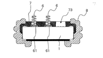
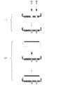
図1は、本発明の一実施の形態に係るマイクロホンの構成を示す断面図である。この図において、本実施の形態のマイクロホンは、2個のコイルバネ6と、2個のコイルバネ6を支持する第1のホルダ(ホルダ)7と、第1のホルダ7を内装するとともにマイクロホンユニット1を抱持する第2のホルダ8とを備えて構成される。コイルバネ6は、密着長が低くなるようにその先端(図1の上側)に行くに従って径が小さくなるテーパ状に形成されている。また、コイルバネ6の基部には座付き部61が形成されている。
(Embodiment 1)
FIG. 1 is a cross-sectional view showing a configuration of a microphone according to an embodiment of the present invention. In this figure, the microphone according to the present embodiment includes two
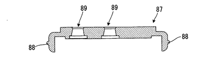
第1のホルダ7は、ABS樹脂等の硬質の絶縁材料からなり、図2の断面図に示すように、周縁部71がL字状になったコ字状に形成されている。即ち、全体的には円板状で、外周縁部71が図に示すように下側に90度折曲がった形状を成している。また、第1のホルダ7には、図2に向かって中央部と左側部分にコイルバネ6を挿入するコイルバネ挿入孔72が形成され、右側部分に位置決め孔(位置決め部)73が形成されている。
The
コイルバネ挿入孔72はテーパ状に形成されたコイルバネ6が挿入できるように、先端(図2の上側)に行くに従って径が小さくなるように形成されている。また、各コイルバネ挿入孔72の下部(図2の下側)には、コイルバネ6の座付き部61の径よりも僅かに大きくしたコイルバネ係止部74が形成されている。
The coil
このコイルバネ係止部74を形成することで、コイルバネ6のコイルバネ挿入孔72からの抜けを防止する。第1のホルダ7の位置決め孔73はコイルバネ挿入孔72と同様にテーパ状に形成されている。図1に戻り、第2のホルダ8は、上述したように、第1のホルダ7とマイクロホンユニット1を収容するものである。
By forming the coil
次に、本実施の形態に係るマイクロホンの製造方法について説明する。
本実施の形態に係るマイクロホンの製造においては、図3に示すコイルバネ整列トレイ10と、図5に示す反転プレート20と、図8に示す治具30とが用いられる。まずこれらについて説明する。
Next, a method for manufacturing the microphone according to the present embodiment will be described.
In the manufacture of the microphone according to the present embodiment, the coil
<コイルバネ整列トレイ10>
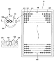
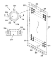
図3は、本実施の形態に係るマイクロホンの製造に用いるコイルバネ整列トレイ10の平面図及びその一部分の拡大図並びに該拡大部分のA−A線断面図である。図3において、コイルバネ整列トレイ10は、第1のホルダ7の2つのコイルバネ挿入孔72に2個のコイルバネ6を挿入するものである。
<Coil
FIG. 3 is a plan view of the coil
コイルバネ整列トレイ10は、図示のように方形状に形成されており、周縁部を除く他の部分が全体的に僅かに凹んでおり、その部分に複数個のコイルバネ整列部101(第1ホルダ挿嵌部)が縦横に形成されている。また、コイルバネ整列トレイ10の長さ方向の両端それぞれの中央部分に反転プレート20と位置合わせするための位置あわせ穴(位置合わせ部)105が形成されている。
The coil
コイルバネ整列部101は、2個のコイルバネ6を挿入する2つのコイルバネ挿入穴102と、2つのコイルバネ挿入穴102と同一直線上に形成された位置決め用の突部103と、2つのコイルバネ挿入穴102と位置決め用の突部103の周囲に形成された環状の外周溝部104とを備える。
The coil
コイルバネ挿入穴102は、その底面に行くに従って径が小さくなるようにテーパ状で且つコイルバネ6を挿入できる大きさに形成されている。位置決め用の突部103は、その上面に行くに従って径が小さくなるようにテーパ状で且つ第1のホルダ7の位置決め孔73と嵌合する大きさに形成されている。外周溝部104は第1のホルダ7の外周縁部71と嵌合する大きさに形成されている。
The coil
本実施の形態に係るマイクロホンの製造においては、まずコイルバネ整列トレイ10の各コイルバネ整列部101にコイルバネ6を2個ずつ挿入し、その後、各コイルバネ整列部101に第1のホルダ7を取り付ける。
In manufacturing the microphone according to the present embodiment, two
第1のホルダ7を取り付ける際には、第1のホルダ7の位置決め孔73をコイルバネ整列トレイ10の位置決め用の突部103に嵌合させることで、第1のホルダ7のコイルバネ挿入孔72とコイルバネ整列トレイ10のコイルバネ挿入穴102の位置が一致する。
When attaching the
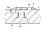
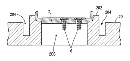
図4は、コイルバネ整列トレイ10のコイルバネ整列部101に第1のホルダ7を装着した状態を示す断面図である。コイルバネ整列トレイ10のコイルバネ整列部101に第1のホルダ7を装着させた状態でコイルバネ整列トレイ10を上下反転させることで、コイルバネ整列トレイ10のコイルバネ挿入穴102に収容した2個のコイルバネ6が第1のホルダ6のコイルバネ挿入孔72に収容される。
FIG. 4 is a cross-sectional view showing a state where the
この際、第1のホルダ6のコイルバネ係止部74がコイルバネ6の座付き部61を係止するので、コイルバネ6が抜け落ちることがない。コイルバネ整列トレイ10を使用することで、コイルバネ6に手を触れることなく、第1のホルダ6のコイルバネ挿入孔72に挿入することが可能となる。
At this time, the coil
なお、第1のホルダ7を装着させた状態でコイルバネ整列トレイ10を上下反転させる場合、そのままでは第1のホルダ7が落下してしまうので、全ての第1のホルダ7のコイルバネ挿入孔72に2個のコイルバネ6を確実に挿入するために反転プレート20を使用する。この反転プレート20については後程説明する。
When the coil
このように、第1のホルダ7に位置決め孔73を設け、またコイルバネ整列トレイ10のコイルバネ整列部101に位置決め孔73と嵌合する位置決め用の突部103を設けることで、コイルバネ整列トレイ10のコイルバネ整列部101に対する位置決めが可能となる。
As described above, the
また、第1のホルダ7の位置決め孔73とコイルバネ整列部101の位置決め用の突部103とをそれぞれテーパ形状とすることで第1のホルダ7のコイルバネ整列トレイ10からの取り外しを容易に行うことが可能となる。
Further, the
これにより、コイルバネ整列トレイ10のコイルバネ整列部101に収容したコイルバネ6の第1のホルダ7への挿入を確実に行えるとともに、第1のホルダ7のコイルバネ整列トレイ10からの取り外しを容易に行うことができる。この際、コイルバネ6には一切触れることがないので、コイルバネ6の品質の均一性を保つことができる。
Thus, the
<反転プレート20>
図5は、本実施の形態に係るマイクロホンの製造に用いる反転プレート20の斜視図及びその一部分の拡大図並びに該拡大部分のB−B線断面図である。この図において、反転プレート20は方形状に形成されており、その一方の面には図示のようにホルダ収容部201が複数個に形成されている。
<
FIG. 5 is a perspective view of the reversing
また、長さ方向の両端それぞれの中央部分にコイルバネ整列トレイ10と位置合わせするための位置決めピン(位置合わせ部)205が形成されている。位置決めピン205は、コイルバネ整列トレイ10に形成された位置決め穴105(図3参照)に嵌合する形状に形成されている。
In addition, positioning pins (alignment portions) 205 for aligning with the coil
また、長さ方向の両端それぞれの左右両側に板状のバネ部206が設けられている。この板状のバネ部206は、反転プレート20に対する整列トレイ10の高さを一定に保ち第1のホルダを外れ易くするとともに、反転プレート20からコイルバネ整列トレイ10を外す際に容易に外れるようにするためのものである。
Further, plate-
コイルバネ反転プレート20のホルダ収容部201は、第1のホルダ7の径より僅かに大きい径の環状突起部202と、環状突起部202の内側に反転プレート20の厚さ方向に貫通した孔203と、環状突起部202の外側に90度の間隔で配置される治具固定用の4つの位置出し溝部204とから構成される。
The holder
孔203の径は環状突起部202の径より小さくなっている。位置出し溝部204は、後述するマイクロホンユニット挿入治具30の爪部301(図8参照)を挿入してマイクロホンユニット挿入治具30を固定するものである。位置出し溝部204の深さはマイクロホンユニット挿入治具30が垂直に自立できる程度以上としている。
The diameter of the
このような構造を採る反転プレート20を用いて、第1のホルダ7のコイルバネ挿入孔72にコイルバネ6を挿入する。すなわち、コイルバネ整列トレイ10に第1のホルダ7を挿入した状態で反転プレート20の位置決めピン205をコイルバネ整列トレイ10の位置決め孔105に合わせて挿入する。
The
この際、反転プレート20の位置決めピン205をコイルバネ整列トレイ10の位置決め穴105とによって高い位置精度が得られる。そして、コイルバネ整列トレイ10と反転プレート20を図示せぬクリップ等で挟むことで確実に密着させる。
At this time, high positioning accuracy can be obtained by the positioning pins 205 of the reversing
その後、一体となった整列トレイ10と反転プレート20を反転させる。コイルバネ整列トレイ10と反転プレート20を確実に密着させ、適度な振動を与えることによって第1のホルダ7とコイルバネ6との遊びを無くすことで、第1のホルダ7へのコイルバネ6の挿入率を高めることが可能となる。
Thereafter, the integrated
但し、このままの密着状態では反転プレート20から第1のホルダ7が抜け難いので、クリップ等を外した後、コイルバネ整列トレイ10と反転プレート20に適度な隙間が空くように反転プレート20のバネ206で調整する。適度な隙間が空いた状態で適度な振動を加えることで第1のホルダ7を反転プレート20から容易に外すことができる。
However, since the
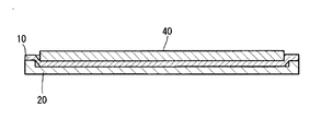
図6は、コイルバネ整列トレイ10と反転プレート20を確実に密着させて反転させたときの状態を示す断面図である。コイルバネ整列トレイ10は、その梱包形態から図のような形状となっており、コイルバネ整列トレイ10が樹脂の場合、軽い振動を加えた時に浮きが発生し、コイルバネ6が飛び出す可能性がある。それを抑えるために金属プレート40を図に示すように挿入する。そして、コイルバネ整列トレイ10、反転プレート20、金属プレート40を一緒にクリップ等で挟み込むことにより、振動による飛び出しを防止できる。
FIG. 6 is a cross-sectional view showing a state when the coil
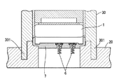
図7は、コイルバネ整列トレイ10と反転プレート20を取り外した後の反転プレート20の一部分を示す断面図である。この図に示すように、反転プレート20の環状突起部202の内側に第1のホルダ7が係止されている。また、第1のホルダ7のコイルバネ挿入孔72にはコイルバネ6が挿入されている。この状態で、マイクロホンユニット挿入治具30(図8参照)を使用して第1のホルダ7にマイクロホンユニット1の取り付けを行う。
FIG. 7 is a cross-sectional view showing a part of the reversing
図8は、反転プレート20に対するマイクロホンユニット挿入治具30の勘合状態を示す断面図である。マイクロホンユニット挿入治具30は、反転プレート20上の第1のホルダ7に対してマイクロホンユニット1の取り付けを行うものである。
FIG. 8 is a cross-sectional view showing a fitting state of the microphone
マイクロホンユニット挿入治具30を使用するときは、その爪部301を反転プレート20の位置出し溝部204に挿入する。マイクロホンユニット挿入治具30の爪部301は反転プレート20の位置出し溝部204の数(4個)と同数有り、それぞれが各位置出し溝部204に挿入される。
When the microphone
反転プレート20にマイクロホンユニット挿入治具30を固定した後、マイクロホンユニット挿入治具30に保持させたマイクロホンユニット1を押し出すことで、マイクロホンユニット1が第1のホルダ7内に挿入される。この際、コイルバネ6の位置決めが精度良く行われているので、確実に2個のコイルバネ6がマイクロホンユニット1の電極パターン11a、11b(図14参照)に接続される。
After fixing the microphone
第1のホルダ7にマイクロホンユニット1を挿入した後、第2のホルダ8で包み込む。第2のホルダ8は、ゴム等の軟質部材からなり、図1に示すように円筒状に形成されており、一方の開口端(図面上側)を押し広げてマイクロホンユニット1と第1のホルダ7を挿入する。
After the
図9及び図10は、本実施の形態に係るマイクロホンの製造工程を示す図である。図11及び図12は、コイルバネ整列トレイ10と反転プレート20を使用した工程(I)の詳細を示す図である。
9 and 10 are diagrams showing a manufacturing process of the microphone according to the present embodiment. FIG. 11 and FIG. 12 are diagrams showing details of the step (I) using the coil
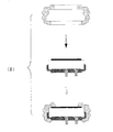
まず、工程(I)において、第1のホルダ7の2つのコイル挿入孔72に2個のコイルバネ6を挿入する。この工程(I)では、コイルバネ整列トレイ10と反転プレート20が使用される。すなわち、図11の(a)に示すように、コイルバネ6と第1のホルダ7を挿入したコイルバネ整列トレイ10に反転プレート20を重ね合わせる。
First, in step (I), the two
次いで、図11の(b)に示すように、重ね合わせたコイルバネ整列トレイ10と反転プレート20を上下反転させる。そして、図12の(c)に示すように抑えプレート40を取り付ける。そして、振動を与えてコイルバネ6を第1のホルダ7のコイルバネ挿入孔72に入るようにする。その後、抑えプレート40とコイルバネ整列トレイ10を外す。
Next, as shown in FIG. 11B, the superposed coil
図12の(d)に、抑えプレート40とコイルバネ整列トレイ10を外した後の反転プレート20を示す。反転プレート20の各ホルダ収容部201には、図7に示すように第1のホルダ7が挿入された状態になっている。工程(I)はこのようにして行われる。
FIG. 12D shows the reversing
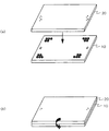
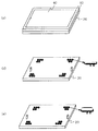
次に、工程(II)において、コイルバネ6が挿入された第1のホルダ7にマイクロホンユニット1を装着する。この工程(II)では、マイクロホンユニット挿入治具30が使用される。
Next, in step (II), the
図12の(e)に、第1のホルダ7にマイクロホンユニット1を装着した後の反転プレート20を示す。工程(II)はこのようにして行われる。次に、工程(III)では、マイクロホンユニット1が装着された第1のホルダ7を第2のホルダ8に挿入する。これにより、マイクロホンが完成する。
FIG. 12E shows the reversing
このように本実施の形態によれば、第1のホルダ7に硬質絶縁材料を使用したので、コイルバネ挿入孔等の寸法精度を出すことが可能となる。また、コイルバネ整列トレイ10にコイルバネ6を収容し、コイルバネ整列トレイ10を反転プレート20と重ね合わせて上下反転することで、コイルバネ整列トレイ10に収容されたコイルバネ6が第1のホルダ7に挿入されるので、コイルバネ6に触れることなく一括して第1のホルダ7にコイルバネ6を挿入することが可能となる。これはコイルバネ6が小さくなってもコイルバネ整列トレイ10のコイルバネ挿入穴102の大きさを変えることで対応できる。
As described above, according to the present embodiment, since the hard insulating material is used for the
マイクロホンユニット1が小さくなって電極パターン11a、11bも小さくなった場合、その電極パターン11a、11bと接触させるコイルバネ6も非常に小さくなければ接触不良の原因につながり、コイルバネ6が小さくなればなるほど扱いが難しくなり、コイルバネ6を変形させる要因につながるが、本実施の形態によれば、これらの課題を解決し、品質の向上及び生産効率を上げることが可能となる。
If the
このように、市場ニーズでもある携帯電話機等の小型化及び品質の安定といった要求に伴い、本実施の形態の製造方法を採用することで、品質向上を図ると伴にその機器に使用されるマイクロホンの小型化を実現することで、携帯電話機等との接続用途に有用である。 In this way, in response to demands such as miniaturization of mobile phones and the like, which are also market needs, and the stabilization of quality, the use of the manufacturing method of the present embodiment improves the quality, and the microphone used for the device. By realizing the downsizing, it is useful for connection with a mobile phone or the like.
なお、第1のホルダ7の位置決め孔73は、凸部103を覆うことができる凹部であっても良い。
Note that the
(実施の形態2)
次に、本発明の実施の形態2について図面を参照して説明する。
(Embodiment 2)
Next, a second embodiment of the present invention will be described with reference to the drawings.
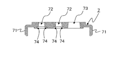
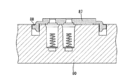
図13は、本実施の形態2のマイクロホンの製造方法に用いる第1のホルダ87の断面図である。図14は、図13のマイクロホンの製造に用いられるコイルバネ整列トレイ80の平面図及びその一部分の拡大図並びに該拡大部分のB−B線断面図である。図15は、図14のコイルバネ整列トレイ80に第1のホルダ87を嵌合させた状態を示す断面図である。図13、図14、および図15において、前述した実施の形態1と同一の構成要素には同一の符号を付けて、その詳細な説明を省略する。ここでは構成が異なる部分のみを説明する。
FIG. 13 is a cross-sectional view of the
図13と実施の形態1で示した図2との相違点は、位置決め孔が無い点と代わりに凸部88が設けられている点である。すなわち、実施の形態1では、ホルダ7は位置決め孔73を有していたが、実施の形態2のホルダ87は位置決め孔を有していない。その代わりにL字部分の両側に凸部88が設けられている。凸部88の大きさは、外周溝部84に嵌らない程度で、かつ後述の拡大溝部83に嵌る大きさである。
The difference between FIG. 13 and FIG. 2 shown in the first embodiment is that there is no positioning hole and a
また、図14に示すように、コイルバネ整列トレイ80では、実施の形態1のコイルバネ整列トレイ10が有していた突部103が省略されている。その代わりに、外周溝部84の一部に拡大溝部83が設けられている。拡大溝部83は、コイルバネ挿入穴85の直線上に位置している。
図15に示すように、拡大溝部83は、第1ホルダ87の凸部88が収まる程度の幅であり、凸部88と拡大溝部83の位置が重なる場合は、第一ホルダ87とコイルバネ整列トレイ80とは互いに嵌合する。一方、凸部88と拡大溝部83の位置が重ならない場合、すなわち、外周溝部84と凸部88とが重なる場合は、第一ホルダ87とコイルバネ整列トレイ80とは互いに嵌合せず、第1ホルダを嵌め込むことができない。
Further, as shown in FIG. 14, in the coil
As shown in FIG. 15, the
このように、硬質材料である第1ホルダに位置決め用の凸部88を設けたので実施の形態1と同様に精度良く位置決めすることができる。
As described above, since the positioning
本発明は、コイルバネの取り付けを人の手で行うことなく自動的に行うことができ、しかもマイクロホンを小型化しても高い位置清精度で取り付けることができるといった効果を有し、携帯電話機等の電子機器への適用が可能である。 The present invention has an effect that the coil spring can be automatically attached without human hands, and can be attached with high positioning accuracy even if the microphone is miniaturized. Applicable to equipment.
1 マイクロホンユニット
6 コイルバネ
7 第1のホルダ
8 第2のホルダ
10 コイルバネ整列トレイ
20 反転プレート
30 マイクロホン挿入治具
40 抑えプレート
61 座付き部
71 外周縁部
72 コイルバネ挿入孔
73 位置決め孔
74 コイルバネ係止部
101 コイルバネ整列部
102 コイルバネ挿入穴
103 突部
104 外周溝部
105 位置合わせ穴
201 ホルダ収容部
202 環状突起部
203 孔
204 位置出し溝部
205 位置決めピン
206 バネ部
DESCRIPTION OF
Claims (16)
前記マイクロホンユニットの電極を外部と接続する導電性の弾性体と、
硬質材料から成り、前記弾性体を保持する弾性体挿入孔と、前記マイクロホンユニットが嵌めこまれるとともに、マイクロホン組立て用トレイ上に複数設けられた溝部に嵌めこまれる形状である外周縁部と、を備える第1のホルダと、
前記外周縁部に前記マイクロホンユニットが差し込まれた状態の前記第1ホルダを収容する第2ホルダと、を備えるマイクロホン装置を、
前記第1ホルダが嵌め込まれる第1ホルダ挿嵌部を複数有し、前記第1ホルダ挿嵌部が、前記第1ホルダの外周縁部と対応する溝部と、前記弾性体を収容する凹部と、を備えるマイクロホン組立て用トレイと、
反転した前記第1ホルダを保持する第1ホルダ収容部を複数有し、前記第1ホルダ収容部が、前記第1ホルダの前記弾性体挿入孔から前記弾性体が突き出す部分を逃がす孔又は凹部を備えている反転プレートと、を用いて組み立てるマイクロホン装置の製造方法において、
前記トレイの凹部に前記弾性体を収容する弾性体収容工程と、
前記トレイの溝部に前記第1ホルダの外周縁部を嵌め込む第1ホルダ嵌め込み工程と、
前記トレイの第1ホルダ挿嵌部と前記反転プレートの第1ホルダ収容部とが対応して重なるように、前記トレイと前記反転プレートとを重ねて上下反転する上下反転工程と、を有するマイクロホン装置の製造方法。 A microphone unit that converts sound signals into electrical signals and outputs them,
A conductive elastic body for connecting the electrode of the microphone unit to the outside;
An elastic body insertion hole made of a hard material and holding the elastic body, and an outer peripheral edge portion having a shape in which the microphone unit is fitted and a plurality of grooves provided on the microphone assembly tray are fitted. A first holder comprising:
A microphone device comprising: a second holder that houses the first holder in a state where the microphone unit is inserted into the outer peripheral edge portion;
A plurality of first holder insertion portions into which the first holder is fitted, wherein the first holder insertion portion is a groove portion corresponding to an outer peripheral edge portion of the first holder, and a concave portion that houses the elastic body; A microphone assembly tray comprising:
There are a plurality of first holder accommodating portions for holding the inverted first holder, and the first holder accommodating portion has a hole or a recess for allowing the elastic body to protrude from the elastic body insertion hole of the first holder. In the manufacturing method of the microphone device assembled using the reversing plate provided,
An elastic body housing step of housing the elastic body in the recess of the tray;
A first holder fitting step of fitting the outer peripheral edge of the first holder into the groove of the tray;
A microphone device having a vertically reversing step of vertically reversing the tray and the reversing plate so that the first holder insertion portion of the tray and the first holder housing portion of the reversing plate overlap correspondingly; Manufacturing method.
前記マイクロホンユニット差込工程において、前記治具を用いて前記マイクロホンユニットの差し込みを行う請求項3に記載のマイクロホン装置の製造方法。 The reversing plate has a groove for fixing a jig for mounting the microphone unit,
The microphone device manufacturing method according to claim 3, wherein in the microphone unit insertion step, the microphone unit is inserted using the jig.
前記マイクロホンユニットの電極を外部と接続する導電性の弾性体と、
硬質材料から成り、前記弾性体を保持する弾性体挿入孔と、前記マイクロホンユニットが嵌めこまれる外周縁部と、を有する第1ホルダと、
前記外周縁部に前記マイクロホンユニットが差し込まれた状態の前記第1ホルダを収容する第2ホルダと、を備え、
前記外周縁部は、前記弾性体を収容する凹部を有するマイクロホン組立て用トレイ上に複数設けられた溝部に嵌めこまれる形状であるマイクロホン装置。 A microphone unit that converts sound signals into electrical signals and outputs them,
A conductive elastic body for connecting the electrode of the microphone unit to the outside;
A first holder made of a hard material and having an elastic body insertion hole for holding the elastic body, and an outer peripheral edge portion into which the microphone unit is fitted;
A second holder for accommodating the first holder in a state where the microphone unit is inserted into the outer peripheral edge,
The microphone device having a shape in which the outer peripheral edge portion is fitted into a plurality of groove portions provided on a microphone assembly tray having a recess for accommodating the elastic body.
前記第1ホルダが嵌め込まれる第1ホルダ挿嵌部を複数有し、
前記第1ホルダ挿嵌部は、前記第1ホルダの外周縁部と対応する溝部と、前記位置決め孔又は凹部と対応する突起部と、前記弾性体を収容する凹部と、を備えるマイクロホン組立て用トレイ。 A microphone assembly tray for use in assembling the microphone device according to claim 7 or 8,
A plurality of first holder insertion portions into which the first holder is fitted;
The first holder insertion portion includes a groove portion corresponding to the outer peripheral edge portion of the first holder, a projection portion corresponding to the positioning hole or the concave portion, and a concave portion for accommodating the elastic body. .
前記第1ホルダが嵌め込まれる第1ホルダ挿嵌部を複数有し、
前記第1ホルダ挿嵌部は、前記第1ホルダの外周縁部と対応する溝部と、前記弾性体を収容する凹部と、を備え、
前記溝部は、前記第1ホルダの前記位置決め凸部と対応する凹部を備えるマイクロホン組立て用トレイ。 A microphone assembly tray for assembling the microphone device according to claim 9,
A plurality of first holder insertion portions into which the first holder is fitted;
The first holder insertion portion includes a groove portion corresponding to an outer peripheral edge portion of the first holder, and a concave portion that houses the elastic body,
The microphone assembly tray, wherein the groove includes a recess corresponding to the positioning protrusion of the first holder.
反転した前記第1ホルダを保持する第1ホルダ収容部を複数有し、
前記第1ホルダ収容部は、前記第1ホルダの前記弾性体挿入孔から前記弾性体が突き出す部分を逃がす孔又は凹部を有する反転用プレート。 A reversing plate used for reversing the microphone assembly tray according to any one of claims 10 to 12, comprising a plurality of first holder accommodating portions for holding the reversed first holder,
The first holder accommodating portion is a reversing plate having a hole or a recess for allowing a portion of the elastic body to protrude from the elastic body insertion hole of the first holder.
Priority Applications (1)
| Application Number | Priority Date | Filing Date | Title |
|---|---|---|---|
| JP2005360761A JP4740728B2 (en) | 2005-12-14 | 2005-12-14 | Microphone device, microphone assembly tray, reversing plate, and method of manufacturing microphone device |
Applications Claiming Priority (1)
| Application Number | Priority Date | Filing Date | Title |
|---|---|---|---|
| JP2005360761A JP4740728B2 (en) | 2005-12-14 | 2005-12-14 | Microphone device, microphone assembly tray, reversing plate, and method of manufacturing microphone device |
Publications (2)
| Publication Number | Publication Date |
|---|---|
| JP2007166314A true JP2007166314A (en) | 2007-06-28 |
| JP4740728B2 JP4740728B2 (en) | 2011-08-03 |
Family
ID=38248691
Family Applications (1)
| Application Number | Title | Priority Date | Filing Date |
|---|---|---|---|
| JP2005360761A Expired - Fee Related JP4740728B2 (en) | 2005-12-14 | 2005-12-14 | Microphone device, microphone assembly tray, reversing plate, and method of manufacturing microphone device |
Country Status (1)
| Country | Link |
|---|---|
| JP (1) | JP4740728B2 (en) |
Cited By (2)
| Publication number | Priority date | Publication date | Assignee | Title |
|---|---|---|---|---|
| JP2009267907A (en) * | 2008-04-28 | 2009-11-12 | Panasonic Corp | Speaker |
| KR102015357B1 (en) * | 2018-05-18 | 2019-09-03 | 주식회사 이엔씨 테크놀로지 | Inspection apparatus for inspecting flat panel display device and stage therefor |
Citations (4)
| Publication number | Priority date | Publication date | Assignee | Title |
|---|---|---|---|---|
| JPH0824801A (en) * | 1994-07-12 | 1996-01-30 | Sony Corp | Magnetic head chip aligner and component aligner |
| JPH09183025A (en) * | 1995-12-28 | 1997-07-15 | Taiyo Yuden Co Ltd | Work aligning jig and work inspecting method |
| JPH1155795A (en) * | 1997-07-30 | 1999-02-26 | Hoshiden Corp | Electlet condenser microphone |
| JP2005223618A (en) * | 2004-02-05 | 2005-08-18 | Star Micronics Co Ltd | Electroacoustic transducer |
-
2005
- 2005-12-14 JP JP2005360761A patent/JP4740728B2/en not_active Expired - Fee Related
Patent Citations (4)
| Publication number | Priority date | Publication date | Assignee | Title |
|---|---|---|---|---|
| JPH0824801A (en) * | 1994-07-12 | 1996-01-30 | Sony Corp | Magnetic head chip aligner and component aligner |
| JPH09183025A (en) * | 1995-12-28 | 1997-07-15 | Taiyo Yuden Co Ltd | Work aligning jig and work inspecting method |
| JPH1155795A (en) * | 1997-07-30 | 1999-02-26 | Hoshiden Corp | Electlet condenser microphone |
| JP2005223618A (en) * | 2004-02-05 | 2005-08-18 | Star Micronics Co Ltd | Electroacoustic transducer |
Cited By (2)
| Publication number | Priority date | Publication date | Assignee | Title |
|---|---|---|---|---|
| JP2009267907A (en) * | 2008-04-28 | 2009-11-12 | Panasonic Corp | Speaker |
| KR102015357B1 (en) * | 2018-05-18 | 2019-09-03 | 주식회사 이엔씨 테크놀로지 | Inspection apparatus for inspecting flat panel display device and stage therefor |
Also Published As
| Publication number | Publication date |
|---|---|
| JP4740728B2 (en) | 2011-08-03 |
Similar Documents
| Publication | Publication Date | Title |
|---|---|---|
| CN101625451B (en) | Lens driver, lens unit using same, and manufacturing method thereof | |
| CN107222081B (en) | Voice coil motor | |
| CN108810767B (en) | Loudspeaker and manufacturing method thereof | |
| US20140241566A1 (en) | Inner Ring Magnet Type Microspeaker | |
| US9113258B2 (en) | Speaker | |
| CN100397954C (en) | speaker | |
| US20130156237A1 (en) | High power micro-speaker | |
| JP2014096220A (en) | Electronic apparatus | |
| US8531845B2 (en) | Structure of anti tamper case for solid state disk | |
| JP5087573B2 (en) | Speaker and manufacturing method thereof | |
| US20120177244A1 (en) | Speaker | |
| KR102549539B1 (en) | Sealing apparatus and method for secondary battery | |
| US20110141708A1 (en) | Electronic device with back-up power supply | |
| JP4740728B2 (en) | Microphone device, microphone assembly tray, reversing plate, and method of manufacturing microphone device | |
| JPH0946793A (en) | Piezoelectric element and piezoelectric audio equipment | |
| JP4205420B2 (en) | Microphone device and holder | |
| US20200045461A1 (en) | Speaker | |
| JP2005136708A (en) | Speaker apparatus and method for manufacturing same | |
| US7010142B2 (en) | Electrical acoustic converter | |
| EP1699258A1 (en) | Electro-acoustic transducer with holder | |
| JP2011192426A (en) | Structure of battery housing part | |
| KR20080035040A (en) | Combined assembly of speaker and intenna, assembly method thereof and portable wireless communication terminal having same | |
| US7152854B2 (en) | Spring mechanism and cell contact mechanism for small electronic device | |
| US7403631B2 (en) | Electro-acoustic transducer | |
| JP5784483B2 (en) | Lens drive device |
Legal Events
| Date | Code | Title | Description |
|---|---|---|---|
| RD02 | Notification of acceptance of power of attorney |
Free format text: JAPANESE INTERMEDIATE CODE: A7422 Effective date: 20071113 |
|
| RD04 | Notification of resignation of power of attorney |
Free format text: JAPANESE INTERMEDIATE CODE: A7424 Effective date: 20071120 |
|
| A621 | Written request for application examination |
Free format text: JAPANESE INTERMEDIATE CODE: A621 Effective date: 20080911 |
|
| A977 | Report on retrieval |
Free format text: JAPANESE INTERMEDIATE CODE: A971007 Effective date: 20100901 |
|
| A131 | Notification of reasons for refusal |
Free format text: JAPANESE INTERMEDIATE CODE: A131 Effective date: 20100914 |
|
| A521 | Request for written amendment filed |
Free format text: JAPANESE INTERMEDIATE CODE: A523 Effective date: 20101115 |
|
| A01 | Written decision to grant a patent or to grant a registration (utility model) |
Free format text: JAPANESE INTERMEDIATE CODE: A01 Effective date: 20110405 |
|
| A61 | First payment of annual fees (during grant procedure) |
Free format text: JAPANESE INTERMEDIATE CODE: A61 Effective date: 20110502 |
|
| R150 | Certificate of patent or registration of utility model |
Free format text: JAPANESE INTERMEDIATE CODE: R150 |
|
| FPAY | Renewal fee payment (event date is renewal date of database) |
Free format text: PAYMENT UNTIL: 20140513 Year of fee payment: 3 |
|
| LAPS | Cancellation because of no payment of annual fees |