JP2007160414A - Needle bearing assembly device - Google Patents
Needle bearing assembly device Download PDFInfo
- Publication number
- JP2007160414A JP2007160414A JP2005356404A JP2005356404A JP2007160414A JP 2007160414 A JP2007160414 A JP 2007160414A JP 2005356404 A JP2005356404 A JP 2005356404A JP 2005356404 A JP2005356404 A JP 2005356404A JP 2007160414 A JP2007160414 A JP 2007160414A
- Authority
- JP
- Japan
- Prior art keywords
- assembly
- bearing
- shaft
- hole
- needle
- Prior art date
- Legal status (The legal status is an assumption and is not a legal conclusion. Google has not performed a legal analysis and makes no representation as to the accuracy of the status listed.)
- Granted
Links
Images


Landscapes
- Automatic Assembly (AREA)
- Mounting Of Bearings Or Others (AREA)
- Rolling Contact Bearings (AREA)
Abstract
Description
この発明は、ニードルベアリングを組み立ててからワークの軸受け穴へ挿入するようにしたニードルベアリングの組付装置に関する。
The present invention relates to a needle bearing assembling apparatus in which a needle bearing is assembled and then inserted into a bearing hole of a workpiece.
このようなニードルベアリングの組付装置は公知であり、例えば、ニードルベアリングの組立治具に投入スロットと組立穴を設け、組立穴へ出入する組立シャフトの先端外周にニードルローラーの保持溝を設け、これに軸方向と平行にして投入スロットから投入されたニードルローラーを嵌合保持させ、この組立シャフトとニードルローラーを、組立穴と同軸に配置されているワークの軸受穴へ押し込み、その後組立シャフトを後退させ、ニードルローラーをワークの軸受穴へグリースで接着保持させてから、ニードルローラーで囲まれた内側空間内へ軸受シャフトを嵌合するようになっている。
上記特許文献1の公知例では、ニードルローラーを組立シャフトの周囲へ保持するので、軸受穴内へニードルローラーを押し込んでから組立シャフトを後退させ、軸受シャフトを嵌合するまではニードルローラーを予め軸受穴内へ塗られたグリースで保持するようになっている。したがって、軸受シャフトを押し込むとき、ニードルローラーの脱落や浮き上がりが生じ、軸受シャフトの押し込みに手間取るおそれがある。また軸受穴に対するグリース塗布作業も必須である。そこで本願は、軸受穴内へニードルローラーをグリース無しで保持できるようにすることを主たる目的とする。
In the known example of Patent Document 1, since the needle roller is held around the assembly shaft, the needle roller is previously moved into the bearing hole until the assembly shaft is retracted after the needle roller is pushed into the bearing hole and the bearing shaft is fitted. It is designed to be held with grease applied to the top. Therefore, when the bearing shaft is pushed in, the needle roller falls off or rises, and there is a risk that it takes time to push the bearing shaft. It is also essential to apply grease to the bearing holes. Therefore, the main purpose of the present application is to enable the needle roller to be held in the bearing hole without grease.
上記課題を解決するため、ニードルベアリングの組付装置に係る請求項1の発明は、フィーダーパイプを介してから外部からニードルローラーが供給される組立治具と、この組立治具と並べて配置されたワークと、組立治具を挟んでワークと反対側に配置され、組立治具へ貫通形成された組立穴の軸線上を進退する組立シャフトとを備え、組立シャフトに支持されたリテーナを組立穴へ入れ、この組立穴から上方へ延びるように形成された投入スロットへニードルローラーを組立穴の軸線方向と平行にして投入し、リテーナのローラー穴へ挿入保持させることによりニードルベアリングを組み立て、その後、ニードルベアリングを組立シャフトで押し出して、組立穴と同軸上に配置されたワークの軸受穴内へ挿入するニードルベアリングの組付装置において、
組立シャフトの先端に軸受けシャフトを同軸で着脱自在に取付け、かつこの軸受けシャフトの外周にリテーナを嵌合した状態で組立穴へ入れ、ニードルローラーをリテーナへ保持させてニードルベアリングを軸受けシャフト上に組み立て、
この組み立てられたニードルベアリングを軸受けシャフトと共にワーク側へ組立シャフトで押し出し、ワークの軸受穴内へニードルベアリングと軸受けシャフトを同時に挿入するようにしたことを特徴とする。
In order to solve the above-mentioned problem, the invention according to claim 1 relating to the needle bearing assembling apparatus includes an assembly jig in which a needle roller is supplied from the outside through a feeder pipe, and the assembly jig is arranged side by side. The assembly includes a workpiece and an assembly shaft that is disposed on the opposite side of the workpiece with the assembly jig interposed therebetween, and advances and retreats on the axis of the assembly hole formed through the assembly jig, and the retainer supported by the assembly shaft is moved to the assembly hole. The needle roller is inserted into the insertion slot formed so as to extend upward from the assembly hole in parallel with the axial direction of the assembly hole, and is inserted into the roller hole of the retainer to assemble the needle bearing. A set of needle bearings in which the bearing is pushed out by the assembly shaft and inserted into the bearing hole of the work arranged coaxially with the assembly hole. In the device,
A bearing shaft is coaxially and detachably attached to the tip of the assembly shaft, and a retainer is fitted on the outer periphery of the bearing shaft and inserted into an assembly hole, and the needle roller is held on the retainer to assemble the needle bearing on the bearing shaft. ,
The assembled needle bearing is extruded to the workpiece side together with the bearing shaft with the assembly shaft, and the needle bearing and the bearing shaft are simultaneously inserted into the bearing hole of the workpiece.
請求項2の発明は上記請求項1において、組立治具の投入スロット内へ加圧エアを注入してニードルローラーを加圧するとともに、フィーダーパイプに加圧エアを逃がすためのエア逃がし部を設けたことを特徴とする。 According to a second aspect of the present invention, in the first aspect, pressurized air is injected into the charging slot of the assembly jig to pressurize the needle roller, and an air escape portion is provided in the feeder pipe for allowing the pressurized air to escape. It is characterized by that.
請求項3の発明は上記請求項1において、投入スロットが、縦方向へ略垂直に延びる第1部分と、横向きに曲がる第2部分と、再び縦方向に曲がって組立穴へ至る第3部分とからなることを特徴とする。 According to a third aspect of the present invention, in the first aspect, the insertion slot has a first portion that extends substantially vertically in the vertical direction, a second portion that bends laterally, and a third portion that bends in the vertical direction and reaches the assembly hole again. It is characterized by comprising.
請求項4の発明は上記請求項1において、ニードルローラーの挿入漏れを検知するための組立検査センサを備えたことを特徴とする。
According to a fourth aspect of the present invention, in the first aspect, an assembly inspection sensor for detecting an insertion leak of the needle roller is provided.
請求項1の発明によれば、軸受シャフトの外周にリテーナを嵌合した状態でニードルローラーを挿入保持させてニードルベアリングを組み立てるので、ニードルベアリングと軸受けシャフト一体化した状態で組み立てできる。
そこで、組み立てられたニードルベアリングを軸受シャフトと一緒にワークの軸受穴へ押し込むと、ニードルベアリングの押し込みと同時に軸受シャフトの差し込みも完了する。このとき、リテーナの中心側においてニードルローラーを軸受シャフトで支持しているから、組立シャフトを後退させても軸受シャフトによりニードルローラーの脱落や浮き上がりを防止でき、ニードルローラーをグリースで保持する必要がなく、予め軸受け穴内へグリースを塗布しておく必要もない。
このため、組立シャフトを後退させてから改めて軸受シャフトを差し込む必要もなく、ニードルベアリングの組付工数を削減でき、組付作業が容易迅速になり、作業を効率化できる。
According to the first aspect of the present invention, the needle roller is inserted and held in a state where the retainer is fitted to the outer periphery of the bearing shaft to assemble the needle bearing, so that the needle bearing and the bearing shaft can be assembled.
Therefore, when the assembled needle bearing is pushed together with the bearing shaft into the bearing hole of the workpiece, the insertion of the bearing shaft is completed simultaneously with the pushing of the needle bearing. At this time, since the needle roller is supported by the bearing shaft on the center side of the retainer, even if the assembly shaft is retracted, the needle shaft can be prevented from falling off and rising, and there is no need to hold the needle roller with grease. It is not necessary to apply grease in advance into the bearing hole.
For this reason, it is not necessary to insert the bearing shaft again after the assembly shaft is retracted, so that the number of assembling steps of the needle bearing can be reduced, the assembling work can be performed easily and quickly, and the work efficiency can be improved.
請求項2の発明によれば、ニードルローラーを加圧エアで迅速に投入スロット内を移動させてリテーナーへ嵌合させることができるとともに、フィーダーパイプにエア逃げ部を設けたので、加圧エアによるフィーダーパイプの異常な内圧上昇を防ぎ、フィーダーパイプ内におけるニードルローラーの逆流を防止できる。 According to the second aspect of the present invention, the needle roller can be quickly moved in the charging slot with pressurized air to be fitted to the retainer, and the feeder pipe is provided with the air escape portion. An abnormal increase in internal pressure of the feeder pipe can be prevented, and back flow of the needle roller in the feeder pipe can be prevented.
請求項3の発明によれば、投入スロットが第1〜第3部分からなり、投入スロット内へ投入されたニードルローラーが垂直方向、略水平方向、略垂直方向と変化するので、この間で姿勢が制御され、ニードルローラーが投入スロット内で立つことなく、軸受け穴の軸線方向と平行な状態でリテーナのローラー穴へ嵌合される。 According to the third aspect of the present invention, the insertion slot is composed of the first to third portions, and the needle roller introduced into the insertion slot changes in the vertical direction, the substantially horizontal direction, and the substantially vertical direction. The needle roller is controlled to be fitted into the roller hole of the retainer in a state parallel to the axial direction of the bearing hole without standing in the charging slot.
請求項4の発明によれば、ニードルローラーの挿入漏れを検知するための組立検査用センサを設けたので、ニードルローラーが嵌合されていないローラー穴を自動的に検出することができる。
According to the invention of claim 4, since the assembly inspection sensor for detecting the insertion leakage of the needle roller is provided, it is possible to automatically detect the roller hole in which the needle roller is not fitted.
以下、図面に基づいて、エンジンのコンロッドをワークとし、この大端部へニードルベアリングを自動的に取付けるための装置を説明する。
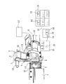
図1は、装置全体の斜視図であり、ワーク1を支持する組立治具2とワーク1を組立治具2側へ押し付け固定するための固定シャフト3を進退させる固定シリンダ4と、組立治具2を挟んで固定シャフト3と反対側に設けられ、ニードルベアリングを組み立てるための組立シャフト5を進退させる組み付けシリンダ6を備える。
Hereinafter, an apparatus for automatically attaching a needle bearing to a large end of a connecting rod of an engine will be described with reference to the drawings.
FIG. 1 is a perspective view of the entire apparatus, an
なお、本願において、固定シャフト3及び組立シャフト5の進退方向とは、組立治具2へ向かう移動を前進、逆方向への移動を後退というものとする。固定シリンダ4はそれ自体が基台上を進退移動自在である。
In the present application, the forward and backward directions of the
ワーク1は長さ方向両端に小端部7及び大端部8を備え、それぞれ軸受穴9、10(図3参照)が設けられている。
軸受穴9には組立治具2の上方へ突出する上方延出部12の上端部から略水平に突出する位置決めピン13が嵌合することにより、組立治具2に対するワーク1の上部が位置決めされる。
The workpiece 1 includes a small end portion 7 and a large end portion 8 at both ends in the length direction, and is provided with
The
組立治具2はニードルベアリングの組立部14を備え、その上部にエアホース15を介して加圧エアが供給される。また、フィーダーパイプ16を介してホッパー17からニードルローラーが組立部14へ送られる。ホッパー17は組立部14の上方に配置され、振動によりニードルローラーを一列に整列させて連続的にフィーダーパイプ16へ送り込む公知のものである。
The assembling
固定シャフト3の外周にはフランジ18が軸線方向へ摺動自在に嵌合支持され、バネ19により大端部8の側面へ押し付けつけ、大端部8を組立治具2の側面へ押し付け固定するように移動付勢される。バネ19はコイルスプリング等適宜構造の弾性部材を使用できる。
A
図2は組立治具2の斜視図である。組立部14には組立穴20が貫通形成され、その一部は透明カバー21によって構成される。透明カバー21は透明樹脂からなり、組立穴20の一部を構成するとともに、後述する投入スロットの一部も構成し、ボルト22により組立治具2の切り欠き部23を覆うようにして着脱自在にに取付けられる。組立部14の上部にはエアホース15のジョイント24が設けられている。上方延出部12の下部は組立部14へ取付一体化されている。
FIG. 2 is a perspective view of the
図3は組立治具2におけるニードルベアリングの組立状態を示す断面図である。固定シャフト3、ワーク1の軸受穴10、組立シャフト5及び組立穴20は同軸に配置される。固定シャフト3の先端は軸受穴10へ嵌合することにより大端部8を組立穴20と同軸に支持する。軸受穴10と組立穴20は同形である。固定シャフト3は筒状であり、中空部3a内に軸受シャフト25を嵌合可能になっている。
FIG. 3 is a cross-sectional view showing an assembly state of the needle bearing in the
軸受シャフト25の他端は組立シャフト5の先端側に形成された軸穴26内へ抜き差し自在に嵌合される。軸受シャフト25の外周部にはリテーナ27が同軸で嵌合される。リテーナ27は筒状であり、周方向等間隔に所定数のローラー穴28が長穴状又は略長方形に形成されている。ローラー穴28の長手方向は軸線C方向と平行になっている。ローラー穴28を挟む軸方向両側はローラー穴28が形成されていない縁部29をなす。縁部29は軸方向一端側(組み付けシリンダ6側)の組立シャフト5の先端側に形成された細径部5aへ嵌合され、これにより軸受シャフト25を同軸保持する。
The other end of the
図はローラー穴28へニードルローラー30を嵌合保持させた状態を示し、この状態ではリテーナ27が組立穴20内において、軸線C方向両端を固定シャフト3及び細径部5aの各先端部で挟み付けて支持される。組立シャフト5は組み付けシリンダ6における図示しない回転機構によりローラー穴28の角度分ずつ等角度で回転するようになっている。このため、固定シャフト3と細径部5aに挟まれたリテーナ27は。組立シャフト5を回転することにより等角度ずつ回転する。全部のローラー穴28へニードルローラー30が嵌合保持されるとニードルベアリング31が組み立てられる。
The figure shows a state in which the
組立部14には組立穴20の径方向上方へ延びる投入スロット32が形成され、その下端は組立穴20に連通開口し、上端は投入口33に連通する。投入口33にはフィーダーパイプ16からニードルローラー30が軸線Cと平行に送り込まれ、その後エアホース15の加圧エアにより下方へ送られ、ローラー穴28へ嵌合される。符号34はジョイント24と連通するエア入り口であり、ここから投入スロット32内へエアホース15からの加圧エアが入る。エア入り口34の位置は投入口33の近傍である。
The
エア入り口34から投入スロット32へ入り込んだ加圧エアによりニードルローラー30がフィーダーパイプ16内を逆流しないようにするため、フィーダーパイプ16には空気抜き穴35が形成され、ニードルローラー30を逆流させる程にフィーダーパイプ16の内圧が異常に上昇したとき、フィーダーパイプ16のエアを逃がして、ニードルローラー30の逆流を防止する。空気抜き穴35の大きさ及び数は任意である。また、形成位置も自由であり、投入口33の近傍からホッパー17までの間で適宜設けられる。
In order to prevent the
図4は組み付け工程を示す図である。図のAはリテーナ27を組立穴20内へ入れる前、すなわち図3の前の状態を示し、この段階では、組立シャフト5には軸受シャフト25とリテーナ27が支持され、組立治具2の組立穴20に対して軸線C上を組立シャフト5が前進する。
FIG. 4 is a diagram showing an assembly process. A in the drawing shows the state before the
一方、固定シリンダ4が前進するとともに固定シャフト3が前方へ伸び出し、その先端を大端部8の軸受け穴10へ挿入して組立治具2側端部まで伸ばし、その軸穴3aに軸受シャフト25の先端側を嵌合することにより、軸受け穴10と組立穴20を同軸に配置し、同時にフランジ18がバネ19により付勢されて大端部8を組立治具2の側面へ押し付ける。固定シャフト3の先端は前進してリテーナ27のワーク1側端部へ押し付けられる。
On the other hand, as the fixed cylinder 4 moves forward, the fixed
その後、リテーナ27が軸受シャフト25と一緒に組立穴20内へセットされ、ローラー穴28を投入スロット32の下端部へ臨ませ、ニードルローラー30がローラー穴28へ嵌合されれば、図3の状態となり、全部のローラー穴28へニードルローラー30が嵌合されるとニードルベアリング31の組立完了となる。
Thereafter, the
図4のBは、ニードルローラー30の組み付け後、ニードルベアリング31を軸受穴10内へ押し込む工程を示し、図3の状態よりさらに組立シャフト5をワーク1側へ前進させ、逆に組立シャフト5を同期させながら同時に後退させると、ニードルベアリング31は軸受シャフト25と一緒に軸受穴10内へ押し込まれる。
FIG. 4B shows a step of pushing the
図4のCはニードルベアリング31をバネ19内へ押し込んだ状態を示し、ニードルベアリング31を軸受穴10内へ押し込みセット後、固定シャフト3と共に固定シリンダ4自体を後退させ、かつ組立シャフト5を後退させると、ニードルベアリング31が軸受シャフト25と一緒に軸受穴10内へ残り、ニードルベアリング31の組付が完了する。
FIG. 4C shows a state in which the
図5は投入スロット32を示す拡大断面図である。投入スロット32の下端は出口40にては組立穴20の内壁頂部に開口する。投入スロット32は投入口33から略垂直に下方へ延びる縦方向の第1部分41と、その下端部で、略水平に曲がり、緩傾斜しながら進行方向前方へ延びる横方向の第2部分42と、その先端から再び略垂直に下方へ延びて出口40へ通じる第3部分43とを備え、第1部分41〜第3部分43の3段に連続して屈曲している。
FIG. 5 is an enlarged cross-sectional view showing the
第1部分41の壁面の一部は透明カバー21に一体形成された凸部44により形成される。すなわち投入スロット32のうち第1部分41の下部以下は切り欠き部23にて開放され、この開放部は透明カバー21を切り欠き部23へ取付けることにより覆われ、凸部44とこれに対面する組立部14の立て壁部との間に投入スロット32の第1部分下部が形成される。投入スロット32の通路断面形状は、図示状態にて第1部分41を図の上方から見たとき、ローラー穴28と略同形の長穴状もしくは略長方形をなし、短い方の幅はニードルローラー30の外径とほぼ同大であり、長い方の幅はニードルローラー30の長さとほぼ同長である。この通路断面形状は投入スロット32の全長において同じ形状を維持する。
A part of the wall surface of the
第2部分42は、通路上壁を凸部44の下部斜面45で構成され、通路下壁をなす組立部14側の段部46との間に形成される。第2部分42の短い方の幅はニードルローラー30の外径程度であり、進行方向における長さはニードルローラー30の一本の長さよりも短い。第3部分43の一部は下部斜面45より下方の透明カバー21の内壁47と組立部14側の下部立て壁48で形成される。
The
ニードルローラー30の進行方向における長さである、第1部分41の図示状態における縦方向長さ、第2部分42の図示状態における横方向長さ、第3部分43の図示状態における縦方向長さ、この順に短くなり、第2部分42の長さは、ニードルローラー30の外径数個分である。第3部分43の長さはニードルローラー30の外径1個分より若干大きい程度である。
The length in the traveling direction of the
投入口33から投入スロット32へ、長さ方向を略軸線方向へ向けた横向き姿勢で入ったニードルローラー30は、エア入り口34からの加圧エアにより第1部分41内を横向き姿勢で落下するが、このとき仮に途中で立ってしまって、ニードルローラー30が長さ方向を上下方向に向けた縦向き姿勢になっても、第1部分41の下端が段部46をなし、この上へ落下することにより倒れて横向き姿勢に変化し、第2部分42へ入る。
The
仮に、段部46の上で縦向き姿勢のままであれば、第2部分42の入り口における狭い方の開口幅がニードルローラー30の外径程度であるため、横向き姿勢になるまで入ることができない。また、仮にはニードルローラー30が縦向き姿勢で落下しても、先端が段部46へ衝突することにより、段部46がクッションとなって、ニードルローラー30を倒れ易くするので、横向き姿勢への変換を容易にする。
If the vertical posture remains on the stepped
なお図5は、軸線C(図3)と直交する方向の断面を示すため、この図においてニードルローラー30の軸直交断面が見える状態が横向き姿勢である。第1部分41にて仮想線で示すニードルローラー30のように長さ方向が見える状態が縦向き姿勢になる。各部分の進行方向における長さは、第1部分41のみがニードルローラー30の長さよりも長いので、ニードルローラー30が進行中に縦向き姿勢になる可能性があるのは第1部分41のみであり、第2部分42及び第3部分43では縦向き姿勢をとり得ない。
Since FIG. 5 shows a cross section in a direction orthogonal to the axis C (FIG. 3), the state in which the cross section perpendicular to the axis of the
第2部分42内へ入ったニードルローラー30は、通路の図示状態上下方向幅がニードルローラー30の外径程度であるから、縦向きに立つことなく横向き姿勢を保ったまま第3部分43へ向かって図の左方へ前方移動する。このとき、ニードルローラー30が進行方向に対して長さ方向が平行になるように回転して傾こうとしても、第2部分42の進行方向における長さがニードルローラー30の長さよりも短いので、このような傾きが生じにくくなる。
The
また、第3部分43の入り口へは傾いた状態のまま入ることができず、ここで軸線方向と平行になるよう整列される。すなわち、第2部分42は、ニードルローラー30のローラー穴28に対する、上下方向及び左右方向における各傾きをそれぞれ規制し、ローラー穴28と平行するように姿勢制御して整列させる機能を有する。
Further, the entrance of the
整列されて第3部分43内へ入ったニードルローラー30は、第3部分43の進行方向長さがニードルローラー30の外径程度であるから、再び立つことはなく第3部分43の出口40から落下し、その下方に位置させたリテーナ27のローラー穴28内へ加圧エアにより確実に嵌合される。このときリテーナ27の内周側に軸受シャフト25が位置するので、ニードルローラー30は軸受シャフト25により支持され、ローラー穴28から中心方向へ落下することなく保持される。ニードルローラー30が立つ等して姿勢変化して投入スロット32内で詰った場合には、カバー21が透明のため、詰まり状態を外部から容易に確認でき、カバー21を外して詰まりを除くことができる。
The
リテーナ27は組立シャフト5により回転され、ローラー穴28が次々に出口40の下方へ移動してニードルローラー30を受け入れる。したがって、リテーナ27を一回転させると、全てのローラー穴28へニードルローラー30が嵌合され、ニードルベアリング31が完成する。この組立完了後、リテーナ27はさらに一回転されて、ニードルローラー30の嵌合漏れが検査される。
The
組立部14内の組立穴20内壁面に臨み、出口40よりリテーナ27の回転方向前方側位置に、組立検査用センサである反射型の光センサ50が設けられ、リテーナ27の外周面へ光を照射して反射光の有無を検出するようになっている。光センサ50の前を通過するローラー穴28の位置にニードルローラー30が嵌合していれば、光センサ50の照射光がニードルローラー30で反射され、これを検知することによりニードルローラー30が嵌合されていることを検出確認する。一方、ニードルローラー30が嵌合されていないと、ローラー穴28は開口しているため、光センサ50の照射光はローラー穴28を通過し、反射しないため、ニードルローラー30の嵌合漏れを自動的に検出する。
A reflective
図1の符号51は、番手の異なるニードルローラーを各別に収容した複数のボックス52の収納ラックであり、このボックスをA、B、C・・として区別する。ある番手のニードルローラー、例えばAのボックス52のものを使用するとき、Aのボックス52を収納ラック51から抜き出し、内容物のニードルローラーをホッパー17内へ投入し、空になったAのボックス52を指定場所53へ置く。
A
指定場所53にはボックスセンサ54が設けられ、ボックス52の種類を識別し、この検出データは操作盤55の制御部へ出力される。一方、作業者は指定場所53へボックス52を置いてから、操作盤55の選択ダイヤル56を回して、使用する番手Aの表示を選択する。この選択内容とボックスセンサ54の検出内容が共にAであれば、制御部は組み付け装置の運転を開始し、相違していれば運転を開始せずにエラー表示する。このため、ニードルローラーとリテーナの異なる組み合わせで組み立てることによる誤組を確実に防止できる。
A
次に、本実施例の作用を説明する。図4に示すように、組立シャフト5へ軸受シャフト25及びリテーナ27を支持させて、組立治具2の組立穴20内へ押し込むことにより、図3に示すように、ニードルローラー30をリテーナ27へ自動的に嵌合保持させてニードルベアリング31を組み立てることができる。この状態で、図4のBに示すように、固定シャフト3を後退させながら組立シャフト5を前進させることにより、軸受シャフト25を一体化したままの状態でニードルベアリング31を軸受穴10内へ押し込む。その後、固定シャフト3及び組立シャフト5を後退させれば、図4のCに示すように、軸受穴10に対するニードルベアリング31の組立が完了する。
Next, the operation of this embodiment will be described. As shown in FIG. 4, the bearing
このとき、最初から軸受シャフト25をリテーナ27の内側へ嵌合してあるので、組立穴20から軸受穴10へニードルベアリングを押し込むときでも、ニードルローラー30がリテーナ27から脱落したり、浮き上がることがなく、正確かつ迅速にリテーナ27を組み込みできる。しかも、軸受シャフト25を一緒に組み込まれるので、組立シャフト5を後退させてから軸受シャフト25を押し込む必要がなく、組立工数を削減でき、組み立て作業を効率化できる。
At this time, since the bearing
したがって、ニードルローラー30をグリースで軸受け穴10内へ接着保持させる必要がなく、予め軸受け穴10内へグリースを塗布しておく必要もない。このため、組立シャフト5を後退させてから改めて軸受シャフト25を差し込む必要もなく、ニードルベアリング31の組付工数を削減でき、組付作業が容易迅速になり、作業を効率化できる。
Therefore, it is not necessary to adhere and hold the
また、加圧エアによりニードルローラー30を迅速に投入スロット32内で移動させてリテーナー27のローラー穴28へ嵌合させることができるとともに、フィーダーパイプ16に空気抜き穴35を設けたので、加圧エアによるフィーダーパイプ16の異常な内圧上昇を防ぎ、フィーダーパイプ16内におけるニードルローラー30の逆流を防止できる。
Further, the
さらに、投入スロット32を、縦方向の第1部分41、横方向の第2部分42及び縦方向の第3部分43と連続して屈曲変化するようにしたので、投入スロット32内へ投入されたニードルローラー30が姿勢が正確に制御され、リテーナ27のローラー穴28へ確実に嵌合保持される。このとき第2部分42の段部46により、ニードルローラー30が第1部分41内で仮に立っても、これを確実に倒して姿勢を変換させることができる。
Further, the
そのうえ、ニードルローラー30の嵌合漏れを検知するための組立検査用センサとして光センサ50を設けたので、ニードルローラー30が嵌合されていないローラー穴28があれば、これを確実かつ自動的に検出することができ、目視検査を不要にできるので、検査の作業効率を向上させることができる。
In addition, since the
1:ワーク、2:組立治具、3:固定シャフト、4:固定シリンダ、5:組立シャフト、6:組み付けシリンダ、10:軸受穴、20:組立穴、25:軸受シャフト、27:リテーナ、28:ローラー穴、30:ニードルローラー、31:ニードルベアリング、32:投入スロット 1: Workpiece, 2: Assembly jig, 3: Fixed shaft, 4: Fixed cylinder, 5: Assembly shaft, 6: Assembly cylinder, 10: Bearing hole, 20: Assembly hole, 25: Bearing shaft, 27: Retainer, 28 : Roller hole, 30: needle roller, 31: needle bearing, 32: loading slot
Claims (4)
組立シャフトの先端に軸受けシャフトを同軸で着脱自在に取付け、かつこの軸受けシャフトの外周にリテーナを嵌合した状態で組立穴へ入れ、ニードルローラーをリテーナへ保持させてニードルベアリングを軸受けシャフト上に組み立て、
この組み立てられたニードルベアリングを軸受けシャフトと共にワーク側へ組立シャフトで押し出し、ワークの軸受穴内へニードルベアリングと軸受けシャフトを同時に挿入するようにしたことを特徴とするニードルベアリングの組付装置。 An assembly jig to which the needle roller is supplied from the outside through the feeder pipe, a workpiece arranged side by side with the assembly jig, and an opposite side of the workpiece across the assembly jig, and penetrates the assembly jig An assembly shaft that advances and retreats along the axis of the formed assembly hole, and a retainer supported by the assembly shaft is inserted into the assembly hole, and the needle roller is inserted into the input slot formed to extend upward from the assembly hole. The needle bearing is assembled by inserting it in parallel with the axial direction of the retainer and inserting it into the roller hole of the retainer. After that, the needle bearing is pushed out by the assembly shaft and into the bearing hole of the work placed coaxially with the assembly hole. In the assembly device of the needle bearing to be inserted,
A bearing shaft is coaxially and detachably attached to the tip of the assembly shaft, and a retainer is fitted on the outer periphery of the bearing shaft and inserted into an assembly hole, and the needle roller is held on the retainer to assemble the needle bearing on the bearing shaft. ,
An assembly apparatus for a needle bearing, wherein the assembled needle bearing is pushed out together with the bearing shaft to the workpiece by the assembly shaft, and the needle bearing and the bearing shaft are simultaneously inserted into the bearing hole of the workpiece.
Priority Applications (1)
| Application Number | Priority Date | Filing Date | Title |
|---|---|---|---|
| JP2005356404A JP4124372B2 (en) | 2005-12-09 | 2005-12-09 | Needle bearing assembly device |
Applications Claiming Priority (1)
| Application Number | Priority Date | Filing Date | Title |
|---|---|---|---|
| JP2005356404A JP4124372B2 (en) | 2005-12-09 | 2005-12-09 | Needle bearing assembly device |
Publications (2)
| Publication Number | Publication Date |
|---|---|
| JP2007160414A true JP2007160414A (en) | 2007-06-28 |
| JP4124372B2 JP4124372B2 (en) | 2008-07-23 |
Family
ID=38243897
Family Applications (1)
| Application Number | Title | Priority Date | Filing Date |
|---|---|---|---|
| JP2005356404A Active JP4124372B2 (en) | 2005-12-09 | 2005-12-09 | Needle bearing assembly device |
Country Status (1)
| Country | Link |
|---|---|
| JP (1) | JP4124372B2 (en) |
Cited By (17)
| Publication number | Priority date | Publication date | Assignee | Title |
|---|---|---|---|---|
| JP2010214538A (en) * | 2009-03-17 | 2010-09-30 | Seiko Instruments Inc | Bearing device, system for manufacturing the same, and method for manufacturing the same |
| JP2010214516A (en) * | 2009-03-16 | 2010-09-30 | Seiko Instruments Inc | Bearing device, system for manufacturing the same and method for manufacturing the same |
| ITVI20110320A1 (en) * | 2011-12-15 | 2013-06-16 | M A S R L | MACHINE FOR THE ASSEMBLY OF MECHANICAL SYSTEMS INCLUDING RELATIVE ROTARY MOTION ELEMENTS |
| WO2013125393A1 (en) * | 2012-02-23 | 2013-08-29 | 日本精工株式会社 | Method for assembling and device for assembling roller bearing |
| JP2015091625A (en) * | 2015-02-03 | 2015-05-14 | Ntn株式会社 | Roller assembly device and roller assembly method |
| KR101546626B1 (en) | 2014-06-25 | 2015-08-21 | 이용진 | Assembly method for niddle-pin of cam flower |
| KR101560094B1 (en) | 2014-06-25 | 2015-10-13 | 이용진 | Assembly method for niddle-pin of cam flower |
| CN104989735A (en) * | 2015-07-09 | 2015-10-21 | 新昌县德尔惠机械厂 | Automatic ball filling equipment for bearing retainer |
| CN105500273A (en) * | 2016-01-21 | 2016-04-20 | 洛阳轴研科技股份有限公司 | Radial roller assembling device for bearing |
| JP2016175156A (en) * | 2015-03-20 | 2016-10-06 | 日本碍子株式会社 | Method for producing assembly |
| CN108000119A (en) * | 2018-01-12 | 2018-05-08 | 重庆安木科技有限公司 | A kind of needle roller feeding system |
| US10057930B2 (en) | 2014-02-19 | 2018-08-21 | Ntt Docomo, Inc. | Mobile communication system and user equipment |
| CN108716511A (en) * | 2018-07-27 | 2018-10-30 | 宁波腾展汽车轴承制造有限公司 | A kind of applanation bearing assembly equipment and its assembly method |
| CN108825668A (en) * | 2018-09-05 | 2018-11-16 | 苏州新豪轴承股份有限公司 | Bearing needle mounting apparatus and plain thrust bearing fill needle system |
| CN112855785A (en) * | 2021-03-27 | 2021-05-28 | 成立强 | Mechanism for positioning inner ring and assembling roller pin and inner ring and positioning and assembling method of roller pin and inner ring |
| CN115355247A (en) * | 2022-08-31 | 2022-11-18 | 陕西法士特齿轮有限责任公司 | Thrust needle roller bearing assembly and speed changer |
| CN118143615A (en) * | 2024-05-13 | 2024-06-07 | 常州市嘉驰滚针轴承有限公司 | Press mounting device for needle bearing assembly |
-
2005
- 2005-12-09 JP JP2005356404A patent/JP4124372B2/en active Active
Cited By (32)
| Publication number | Priority date | Publication date | Assignee | Title |
|---|---|---|---|---|
| JP2010214516A (en) * | 2009-03-16 | 2010-09-30 | Seiko Instruments Inc | Bearing device, system for manufacturing the same and method for manufacturing the same |
| JP2010214538A (en) * | 2009-03-17 | 2010-09-30 | Seiko Instruments Inc | Bearing device, system for manufacturing the same, and method for manufacturing the same |
| ITVI20110320A1 (en) * | 2011-12-15 | 2013-06-16 | M A S R L | MACHINE FOR THE ASSEMBLY OF MECHANICAL SYSTEMS INCLUDING RELATIVE ROTARY MOTION ELEMENTS |
| CN103619532B (en) * | 2012-02-23 | 2016-04-20 | 日本精工株式会社 | The apparatus for assembling of roller bearing |
| KR101568954B1 (en) | 2012-02-23 | 2015-11-12 | 닛뽄 세이꼬 가부시기가이샤 | Method for assembling and device for assembling roller bearing |
| WO2013125392A1 (en) * | 2012-02-23 | 2013-08-29 | 日本精工株式会社 | Roller alignment device and roller alignment method |
| CN103717348A (en) * | 2012-02-23 | 2014-04-09 | 日本精工株式会社 | Roller alignment device and roller alignment method |
| KR101622500B1 (en) | 2012-02-23 | 2016-05-18 | 닛뽄 세이꼬 가부시기가이샤 | Roller alignment device and roller alignment method |
| JP5725254B2 (en) * | 2012-02-23 | 2015-05-27 | 日本精工株式会社 | Roller alignment apparatus and roller alignment method |
| JP5737472B2 (en) * | 2012-02-23 | 2015-06-17 | 日本精工株式会社 | Roller bearing assembly apparatus and assembly method |
| CN103619532A (en) * | 2012-02-23 | 2014-03-05 | 日本精工株式会社 | Method for assembling and device for assembling roller bearing |
| WO2013125393A1 (en) * | 2012-02-23 | 2013-08-29 | 日本精工株式会社 | Method for assembling and device for assembling roller bearing |
| US9797455B2 (en) | 2012-02-23 | 2017-10-24 | Nsk Ltd. | Roller bearing assembly apparatus and roller bearing assembly method |
| EP2818275A4 (en) * | 2012-02-23 | 2015-12-02 | Nsk Ltd | Method for assembling and device for assembling roller bearing |
| US9611895B2 (en) | 2012-02-23 | 2017-04-04 | Nsk Ltd. | Roller alignment device and roller alignment method |
| EP2818276A4 (en) * | 2012-02-23 | 2015-12-09 | Nsk Ltd | Roller alignment device and roller alignment method |
| US10057930B2 (en) | 2014-02-19 | 2018-08-21 | Ntt Docomo, Inc. | Mobile communication system and user equipment |
| KR101560094B1 (en) | 2014-06-25 | 2015-10-13 | 이용진 | Assembly method for niddle-pin of cam flower |
| KR101546626B1 (en) | 2014-06-25 | 2015-08-21 | 이용진 | Assembly method for niddle-pin of cam flower |
| JP2015091625A (en) * | 2015-02-03 | 2015-05-14 | Ntn株式会社 | Roller assembly device and roller assembly method |
| JP2016175156A (en) * | 2015-03-20 | 2016-10-06 | 日本碍子株式会社 | Method for producing assembly |
| CN104989735B (en) * | 2015-07-09 | 2017-09-12 | 新昌县德尔惠机械厂 | Retainer fills out ball equipment automatically |
| CN104989735A (en) * | 2015-07-09 | 2015-10-21 | 新昌县德尔惠机械厂 | Automatic ball filling equipment for bearing retainer |
| CN105500273A (en) * | 2016-01-21 | 2016-04-20 | 洛阳轴研科技股份有限公司 | Radial roller assembling device for bearing |
| CN108000119A (en) * | 2018-01-12 | 2018-05-08 | 重庆安木科技有限公司 | A kind of needle roller feeding system |
| CN108000119B (en) * | 2018-01-12 | 2023-12-12 | 重庆安木科技有限公司 | Rolling needle feeding system |
| CN108716511A (en) * | 2018-07-27 | 2018-10-30 | 宁波腾展汽车轴承制造有限公司 | A kind of applanation bearing assembly equipment and its assembly method |
| CN108716511B (en) * | 2018-07-27 | 2023-11-17 | 宁波腾展汽车轴承制造有限公司 | Plane pressure bearing assembly equipment and assembly method thereof |
| CN108825668A (en) * | 2018-09-05 | 2018-11-16 | 苏州新豪轴承股份有限公司 | Bearing needle mounting apparatus and plain thrust bearing fill needle system |
| CN112855785A (en) * | 2021-03-27 | 2021-05-28 | 成立强 | Mechanism for positioning inner ring and assembling roller pin and inner ring and positioning and assembling method of roller pin and inner ring |
| CN115355247A (en) * | 2022-08-31 | 2022-11-18 | 陕西法士特齿轮有限责任公司 | Thrust needle roller bearing assembly and speed changer |
| CN118143615A (en) * | 2024-05-13 | 2024-06-07 | 常州市嘉驰滚针轴承有限公司 | Press mounting device for needle bearing assembly |
Also Published As
| Publication number | Publication date |
|---|---|
| JP4124372B2 (en) | 2008-07-23 |
Similar Documents
| Publication | Publication Date | Title |
|---|---|---|
| JP4124372B2 (en) | Needle bearing assembly device | |
| CN101045278B (en) | An apparatus for assembling the inserts of disposable gas lighters | |
| EP3593938B1 (en) | Apparatus for and method of installing pre-molded seal caps | |
| CN106442534A (en) | Automatic detection platform | |
| JP5101363B2 (en) | Tube cutting device | |
| TWI518005B (en) | Work insertion apparatus | |
| KR101072880B1 (en) | Fine metal pipe end forming apparatus | |
| US5375756A (en) | Apparatus for assembling and welding final end plugs to nuclear fuel-containing cladding tubes and inspecting the welds, all on an automated basis | |
| JP5081033B2 (en) | Tube cutting device | |
| JP7121829B1 (en) | resin pipe cutting system | |
| KR101988018B1 (en) | Spindle thread machining system that can detect the deformation of dice | |
| CN212041528U (en) | Detection device for needle roller bearing | |
| FR2602879A1 (en) | METHOD AND APPARATUS FOR PRODUCING A MODEL FOR LENS OPENING IN A GLASSES FRAME | |
| JP5073551B2 (en) | Tube cutting device | |
| CN115319254B (en) | Welding machine | |
| CN110014282A (en) | It is intubated housing automatic assembling machine | |
| US20160356725A1 (en) | Apparatus and method for inspection of a mid-length supported steering column assembly | |
| JP5073550B2 (en) | Tube cutting device | |
| JP5073553B2 (en) | Tube cutting device | |
| CN106019399A (en) | Weld joint detection device | |
| JPH0329745Y2 (en) | ||
| JP5073552B2 (en) | Tube cutting device | |
| JPH10227602A (en) | Capillary tube inspecting instrument | |
| JP5101365B2 (en) | Tube cutting device | |
| JP2019136731A (en) | Filler pipe weldment method and device therefor |
Legal Events
| Date | Code | Title | Description |
|---|---|---|---|
| A977 | Report on retrieval |
Free format text: JAPANESE INTERMEDIATE CODE: A971007 Effective date: 20080423 |
|
| TRDD | Decision of grant or rejection written | ||
| A01 | Written decision to grant a patent or to grant a registration (utility model) |
Free format text: JAPANESE INTERMEDIATE CODE: A01 Effective date: 20080430 |
|
| A01 | Written decision to grant a patent or to grant a registration (utility model) |
Free format text: JAPANESE INTERMEDIATE CODE: A01 |
|
| A61 | First payment of annual fees (during grant procedure) |
Free format text: JAPANESE INTERMEDIATE CODE: A61 Effective date: 20080430 |
|
| R150 | Certificate of patent or registration of utility model |
Ref document number: 4124372 Country of ref document: JP Free format text: JAPANESE INTERMEDIATE CODE: R150 Free format text: JAPANESE INTERMEDIATE CODE: R150 |
|
| FPAY | Renewal fee payment (event date is renewal date of database) |
Free format text: PAYMENT UNTIL: 20110516 Year of fee payment: 3 |
|
| FPAY | Renewal fee payment (event date is renewal date of database) |
Free format text: PAYMENT UNTIL: 20110516 Year of fee payment: 3 |
|
| FPAY | Renewal fee payment (event date is renewal date of database) |
Free format text: PAYMENT UNTIL: 20120516 Year of fee payment: 4 |
|
| FPAY | Renewal fee payment (event date is renewal date of database) |
Free format text: PAYMENT UNTIL: 20130516 Year of fee payment: 5 |
|
| FPAY | Renewal fee payment (event date is renewal date of database) |
Free format text: PAYMENT UNTIL: 20130516 Year of fee payment: 5 |
|
| FPAY | Renewal fee payment (event date is renewal date of database) |
Free format text: PAYMENT UNTIL: 20140516 Year of fee payment: 6 |