JP2007155128A - Motor actuator - Google Patents
Motor actuator Download PDFInfo
- Publication number
- JP2007155128A JP2007155128A JP2006301344A JP2006301344A JP2007155128A JP 2007155128 A JP2007155128 A JP 2007155128A JP 2006301344 A JP2006301344 A JP 2006301344A JP 2006301344 A JP2006301344 A JP 2006301344A JP 2007155128 A JP2007155128 A JP 2007155128A
- Authority
- JP
- Japan
- Prior art keywords
- louver
- drive device
- support member
- end side
- transmission mechanism
- Prior art date
- Legal status (The legal status is an assumption and is not a legal conclusion. Google has not performed a legal analysis and makes no representation as to the accuracy of the status listed.)
- Pending
Links
- 230000033001 locomotion Effects 0.000 claims abstract description 21
- 230000005540 biological transmission Effects 0.000 claims description 19
- 238000010586 diagram Methods 0.000 description 5
- 230000005484 gravity Effects 0.000 description 3
- 230000010355 oscillation Effects 0.000 description 3
- 230000000694 effects Effects 0.000 description 1
- 239000000284 extract Substances 0.000 description 1
Images


Landscapes
- Air-Flow Control Members (AREA)
- Transmission Devices (AREA)
Abstract
Description
本発明は、支持部材を揺動または/および直動させるとともに、当該支持部材の先端側で被駆動部材を回転させるモータアクチュエータに関するものである。 The present invention relates to a motor actuator that swings or / and linearly moves a support member and rotates a driven member on the front end side of the support member.
エアコンや温風暖房器などの吹き出し口には、長手方向の複数箇所でルーバ支持部材に支持された状態にルーバが配置され、かかるルーバは、ステッピングモータなどにより回転駆動されて向きを切り換えるようになっている(例えば、特許文献1参照)。
近年、エアコンなどではルーバの位置や姿勢をさらに複雑に制御して部屋全体に冷風や温風が均一に行き渡るようにすることが検討されている。このような構成を実現するには、先端側でルーバを回転可能に支持する支持部材に揺動動作または/および直動動作を行わせればよい。その際、直動用駆動装置、揺動用駆動装置、回転用駆動装置に歯車伝達機構を設けると、ルーバに風が当たった際などにおいて、歯車のバックラッシュの影響でルーバが不用意な動きを行うという問題点がある。 In recent years, in air conditioners and the like, it has been studied to control the louver position and posture in a more complicated manner so that cold air and hot air are evenly distributed throughout the room. In order to realize such a configuration, a swinging operation and / or a linear motion operation may be performed on the support member that rotatably supports the louver on the distal end side. At that time, if a gear transmission mechanism is provided in the linear drive device, the swing drive device, and the rotation drive device, the louver will perform an inadvertent movement due to the backlash of the gear when the wind hits the louver. There is a problem.
また、回転用駆動装置によって支持部材の先端でルーバを回転させるには、支持部材上における先端側にモータを配置すればよいが、支持部材自身を駆動する場合、先端側にモータを配置すると、支持部材の先端側に重心が位置し、支持部材に対する揺動用駆動装置または/および直動用駆動装置に過大な負荷がかかるという問題点がある。 Further, in order to rotate the louver at the tip of the support member by the rotation drive device, a motor may be arranged on the tip side on the support member, but when driving the support member itself, if the motor is arranged on the tip side, There is a problem that the center of gravity is located on the front end side of the support member, and an excessive load is applied to the swing drive device and / or the linear drive device for the support member.
以上の問題点に鑑みて、本発明の課題は、被駆動部材の不用意な動きを防止することのできるモータアクチュエータを提供することにある。 In view of the above problems, an object of the present invention is to provide a motor actuator that can prevent inadvertent movement of a driven member.
次に、本発明の課題は、支持部材の先端側で被駆動部材を回転させるとともに、支持部材自身についても揺動または直動させる場合でも、支持部材に対する駆動装置の負荷を軽減することのできるモータアクチュエータを提供することにある。 Next, an object of the present invention is to reduce the load of the drive device on the support member even when the driven member is rotated on the tip side of the support member and the support member itself is also swung or linearly moved. It is to provide a motor actuator.
上記課題を解決するために、本発明に係るモータアクチュエータでは、支持部材と、該支持部材の先端側に回転可能に支持された被駆動部材と、前記支持部材を直動させる直動用駆動装置と、前記被駆動部材を回転させる回転用駆動装置とを有し、前記直動用駆動装置および前記回転用駆動装置のうちの少なくとも一方は、2つのプーリ間にベルトが掛け渡された動力伝達機構を備えていることを特徴とする。 In order to solve the above-described problems, in the motor actuator according to the present invention, a support member, a driven member rotatably supported on the distal end side of the support member, and a linear drive device that linearly moves the support member; A rotation drive device that rotates the driven member, and at least one of the linear motion drive device and the rotation drive device has a power transmission mechanism in which a belt is stretched between two pulleys. It is characterized by having.
本発明の別の形態に係るモータアクチュエータでは、支持部材と、該支持部材の先端側に回転可能に支持された被駆動部材と、前記支持部材を揺動させる揺動用駆動装置と、前記被駆動部材を回転させる回転用駆動装置とを有し、前記揺動用駆動装置および前記回転用駆動装置のうちの少なくとも一方は、2つのプーリ間にベルトが掛け渡された動力伝達機構を備えていることを特徴とする。 In a motor actuator according to another aspect of the present invention, a support member, a driven member rotatably supported on the distal end side of the support member, a swing drive device that swings the support member, and the driven A rotation drive device that rotates the member, and at least one of the swing drive device and the rotation drive device includes a power transmission mechanism in which a belt is stretched between two pulleys. It is characterized by.
本発明のさらに別の形態に係るモータアクチュエータでは、支持部材と、該支持部材の先端側に回転可能に支持された被駆動部材と、前記支持部材を直動させる直動用駆動装置と、前記支持部材を駆動して前記被駆動部材を揺動させる揺動用駆動装置と、前記被駆動部材を回転駆動する回転用駆動装置とを有し、前記直動用駆動装置、前記揺動用駆動装置および前記回転用駆動装置のうちの少なくとも一方は、2つのプーリ間にベルトが掛け渡された動力伝達機構を備えていることを特徴とする。 In a motor actuator according to still another aspect of the present invention, a support member, a driven member rotatably supported on the distal end side of the support member, a linear motion drive device that linearly moves the support member, and the support A swing drive device that drives a member to swing the driven member; and a rotation drive device that rotationally drives the driven member. The linear drive device, the swing drive device, and the rotation At least one of the drive devices for use includes a power transmission mechanism in which a belt is stretched between two pulleys.
本発明において、前記動力伝達機構は少なくとも前記回転用駆動装置に構成され、当該回転用駆動装置では、前記支持部材の基端側に搭載されたモータの回転出力が前記動力伝達機構を介して先端側に伝達されることが好ましい。揺動動作または/および直動動作を行う支持部材の先端側で被駆動部材を回転させるにあたって、支持部材の基端側にモータを配置すると、支持部材の重心が先端側に偏らないので、支持部材に対する揺動用駆動装置または/および直動用駆動装置に加わる負荷が小さい。それ故、揺動用駆動装置または/および直動用駆動装置に小型のモータを用いればよい。また、支持部材の基端側にモータを配置すると、被駆動部材までの距離が長くなるので、歯車列を用いると、バックラッシュの影響で被駆動部材が不用意な動きを行ってしまうが、本発明では、動力伝達機構としてベルト機構を用いたので、バックラッシュが発生せず、被駆動部材の不用意な動きを防止することができる。 In the present invention, the power transmission mechanism is configured at least in the rotation drive device, and in the rotation drive device, a rotation output of a motor mounted on the proximal end side of the support member is forwardly transferred through the power transmission mechanism. Preferably transmitted to the side. When the driven member is rotated on the distal end side of the support member that performs the swinging operation and / or the linear motion operation, if the motor is disposed on the proximal end side of the support member, the center of gravity of the support member is not biased toward the distal end side. The load applied to the swing drive device and / or the linear drive device on the member is small. Therefore, a small motor may be used for the swing drive device and / or the linear drive device. In addition, when the motor is arranged on the base end side of the support member, the distance to the driven member becomes long, so when the gear train is used, the driven member performs inadvertent movement due to the influence of backlash. In the present invention, since the belt mechanism is used as the power transmission mechanism, backlash does not occur and inadvertent movement of the driven member can be prevented.
本発明では、動力伝達機構にベルト機構を用いているため、バックラッシュが発生せず、被駆動部材の不用意な動きを防止することができる。 In the present invention, since a belt mechanism is used as the power transmission mechanism, backlash does not occur and inadvertent movement of the driven member can be prevented.
以下に、図面を参照して、本発明を適用したモータアクチュエータを説明する。 A motor actuator to which the present invention is applied will be described below with reference to the drawings.
(全体構成)
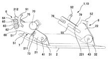
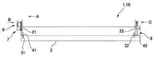
図1および図2は、本発明を適用したモータアクチュエータを備えたルーバ装置の斜視図および平面図である。図1および図2において、本形態のルーバ装置1は、所定の幅寸法をもって延びた板状のルーバ2と、このルーバ2の長手方向の3箇所でルーバ2を支持する複数のルーバ支持部材21、22とを有している。複数のルーバ支持部材21、22は、風の通路を遮らないようにルーバ2の長手方向と直交する板状であり、各々の先端部は、ルーバ2の上面で起立する連結板31、32を支軸41、42を介して回転可能に支持している。
(overall structure)
1 and 2 are a perspective view and a plan view of a louver device including a motor actuator to which the present invention is applied. 1 and 2, a louver device 1 according to this embodiment includes a plate-
2つのルーバ支持部材21のうち、ルーバ支持部材21には、その基端側から先端側に向けてU字形状の切り欠き212が形成され、長さ方向の略中央部分には、長さ方向に長辺を向ける矩形穴211が形成されている。矩形穴211における上辺部にはラックが形成されている。これに対して、ルーバ支持部材22には、長さ方向の略中央部分にルーバ支持部材23の長さ方向に延びた長穴221が形成され、長穴221内にはガイドピン55が位置している。
Of the two
(ルーバ駆動装置の構成)
図3は、図1に示すルーバ装置の一方側端部に位置するルーバ支持部材周辺を抜き出して示す平面図である。図4(a)、(b)は、図1に示すルーバ装置を矢印Bで示す方向からみたときの説明図、および矢印Aで示す方向からみたときの説明図である。図5は、図1に示すルーバ装置を矢印Cで示す方向からみたときの説明図である。
(Configuration of louver drive device)
FIG. 3 is a plan view showing the louver support member and its surroundings located at one end of the louver device shown in FIG. 4A and 4B are an explanatory diagram when the louver device shown in FIG. 1 is viewed from the direction indicated by the arrow B and an explanatory diagram when viewed from the direction indicated by the arrow A. FIG. FIG. 5 is an explanatory diagram when the louver device shown in FIG. 1 is viewed from the direction indicated by the arrow C.
本形態のルーバ装置1は、ルーバ支持部材21の切り欠き212には支軸65が通っており、この支軸65にはピニオン64が固着されている。また、ピニオン64の近傍には、円弧状の公転扇ギア91が配置されており、公転扇ギア91はエアコン本体に両端部が固定されている。また、支軸65は、エアコン本体に対して軸線周りに回転可能、かつ、公転扇ギア91の円弧形状に沿って移動可能な状態にエアコン本体に支持されている。この状態で、公転扇ギア91の円弧部に形成された外歯にピニオン64が噛み合うので、ルーバ装置1はエアコン本体に保持された状態となる。
In the louver device 1 of this embodiment, a
また、本形態のルーバ装置1には、第1のルーバ駆動装置6、第2のルーバ駆動装置7、および第3のルーバ駆動装置8を備えたモータアクチュエータ10が構成されている。
Further, the louver device 1 according to the present embodiment includes a
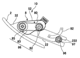
まず、図3および図4(a)、(b)において、第1のルーバ駆動装置6(揺動用駆動装置)は、ルーバ支持部材21におけるルーバ支持位置(支軸41を通る位置)から外れた位置を通る第1の軸線(図示せず)周りにルーバ2を公転させるためのものである。より具体的には、第1のルーバ駆動装置6は、ルーバ支持部材21の側方に配置されたモータケース51内に固定された第1のステッピングモータ60と、この第1のステッピングモータ60の出力軸62に固着されたピニオン63と、このピニオン63および公転扇ギア91に噛み合うピニオン64とを有している。
First, in FIG. 3 and FIGS. 4A and 4B, the first louver drive device 6 (swinging drive device) is out of the louver support position (position passing through the support shaft 41) in the
このため、第1のステッピングモータ60が作動すると、ルーバ支持部材21の側では、第1のステッピングモータ60の回転がピニオン63を介してピニオン64に伝達される結果、ピニオン64が公転扇ギア91の円弧面に沿って上下動するとともにU字形状の切り欠き212内の支軸65が上下動するので、第1のルーバ支持部材21の先端側が揺動する。かかる動作に従動して、ルーバ2が第1の軸線周りに双方向に公転する。
For this reason, when the first stepping
第2のルーバ駆動装置7(直動用駆動装置)は、ルーバ2をその長手方向と直交する方向で前進あるいは後退させるためのものである。より具体的には、第2のルーバ駆動装置7は、ルーバ支持部材21の側方に配置されたモータケース51内に固定された第2のステッピングモータ70と、この第2のステッピングモータ70の出力軸71に固着されたピニオン72と、このピニオン72および矩形穴211の上辺部に形成されたラックと噛み合うピニオン73とを有している。ここで、ラックはルーバ支持部材21の方に形成されている一方、ピニオン73はモータケース51の側に回転可能に支持されている。
The second louver drive device 7 (linear motion drive device) is for moving the
このため、第2のステッピングモータ70が作動すると、ルーバ支持部材21の側では、第2のステッピングモータ70の回転がピニオン73およびラックに伝達される結果、第1のルーバ支持部材21は、その長手方向に前進あるいは後退する。かかる動作に従動して、ルーバ2がルーバ支持部材21の長手方向に前進あるいは後退する。
For this reason, when the second stepping
図5において、第3のルーバ駆動装置8(回転用駆動装置)は、ルーバ支持部材21、22上におけるルーバ支持位置(支軸41、42の位置)を通る第2の軸線(図示せず)周りにルーバ2を自転させるためのものである。より具体的には、第3のルーバ駆動装置8は、第2のルーバ支持部材22の基端側に固定されたモータケース52内に配置された第3のステッピングモータ80と、動力伝達機構86とを有しており、動力伝達機構86は、ステッピングモータ80の出力軸に固着されたプーリ82と、支軸42周りに回転可能な状態で連結板32に支持されたプーリ84と、プーリ82、84に掛け渡されたタイミングベルト83とを備えている。
In FIG. 5, the third louver drive device 8 (rotation drive device) has a second axis (not shown) passing through the louver support positions (positions of the
このため、第3のステッピングモータ80が作動すると、ルーバ支持部材22の側において、第3のステッピングモータ80の回転が動力伝達機構86を介して連結板32に伝達される結果、ルーバ2は、支軸41、42、43を通る第2の軸線周りに双方向に回転する。
For this reason, when the
なお、ルーバ支持部材22では、ルーバ支持部材21の側の揺動や直動に追従できるように、長穴221内にはガイドピン55が位置しているとともに、基端側から先端側に向けてU字形状の切り欠き222が形成されている。また、切り欠き222には支軸96が通っており、この支軸96にはピニオン97が固着されている。また、ピニオン97の近傍には、円弧状の公転扇ギア92が配置されており、公転扇ギア92はエアコン本体に両端部が固定されている。また、支軸96は、エアコン本体に対して軸線周りに回転可能、かつ、公転扇ギア92の円弧形状に沿って移動可能な状態にエアコン本体に支持されている。
In the
ここで、第1のルーバ駆動装置6、第2のルーバ駆動装置7、および第3のルーバ駆動装置8は各々が独立して制御される。このため、第1のルーバ駆動装置6および第2のルーバ駆動装置7を所定のタイミングで動作させれば、支軸41、42、43を所定の軌跡に沿って移動させることができる。
Here, each of the first
(本形態の主な効果)
以上説明したように、本形態では、第3のルーバ駆動装置8によって、揺動動作および直動動作を行うルーバ支持部材22の先端側でルーバ2を回転させるにあたって、ルーバ支持部材22の基端側にステッピングモータ80を配置している。このため、ルーバ支持部材22の重心が先端側に偏らないので、ルーバ支持部材21、22に対する第1のルーバ駆動装置6(揺動用駆動装置)および第2のルーバ駆動装置7(直動用駆動装置)に加わる負荷が小さい。それ故、第1のルーバ駆動装置6および第2のルーバ駆動装置7に用いるモータとしては、小型のステッピングモータ60、70を用いればよい。
(Main effects of this form)
As described above, in the present embodiment, when the
また、ルーバ支持部材22の基端側にステッピングモータ80を配置すると、ルーバ2までの距離が長くなるので、歯車列を用いると、ルーバ2が風を受けた際にバックラッシュの影響でルーバ2が不用意な動きを行ってしまうが、本形態では、動力伝達機構86としてベルト機構を用いたので、バックラッシュが発生せず、ルーバ2の不用意な動きを防止することができる。
Further, if the stepping
[その他の実施の形態]
上記実施の形態では、第1のルーバ駆動装置6(揺動用駆動装置)、第2のルーバ駆動装置7(直動用駆動装置)、および第3のルーバ駆動装置8(回転用駆動装置)のうち、第3のルーバ駆動装置8において、ベルト機構からなる動力伝達機構86を設けたが、例えば、図6に示すように、第1のルーバ駆動装置6(揺動用駆動装置)、および第2のルーバ駆動装置7(直動用駆動装置)でも、ベルト機構からなる動力伝達機構を用いてもよい。すなわち、第1のルーバ駆動装置6では、第1のステッピングモータ60の出力軸62にプーリ67を固着する一方、公転扇ギア91に噛み合うピニオン64と同軸状にプーリ69を構成し、これらのプーリ67、69間にタイミングベルト68を掛け渡す。また、第2のルーバ駆動装置7では、ステッピングモータ70の出力軸71にプーリ77を固着する一方、ラックと噛み合うピニオン73と同軸状にプーリ79を構成し、これらのプーリ間にタイミングベルト78を掛け渡す。
[Other embodiments]
In the above embodiment, the first louver drive device 6 (oscillation drive device), the second louver drive device 7 (linear motion drive device), and the third louver drive device 8 (rotation drive device). In the third
1 ルーバ装置
2 ルーバ
6 第1のルーバ駆動装置(揺動用駆動装置)
7 第2のルーバ駆動装置(直動用駆動装置)
8 第3のルーバ駆動装置(回転用駆動装置)
10 モータアクチュエータ
21、22 ルーバ支持部材
60 第1のステッピングモータ
70 第2のステッピングモータ
80 第3のステッピングモータ
DESCRIPTION OF SYMBOLS 1
7 Second louver drive device (linear motion drive device)
8 Third louver drive device (rotation drive device)
DESCRIPTION OF
Claims (4)
前記直動用駆動装置および前記回転用駆動装置のうちの少なくとも一方は、2つのプーリ間にベルトが掛け渡された動力伝達機構を備えていることを特徴とするモータアクチュエータ。 A support member; a driven member rotatably supported on the distal end side of the support member; a linear drive device that linearly moves the support member; and a rotation drive device that rotates the driven member. ,
At least one of the linear motion drive device and the rotation drive device includes a power transmission mechanism in which a belt is stretched between two pulleys.
前記揺動用駆動装置および前記回転用駆動装置のうちの少なくとも一方は、2つのプーリ間にベルトが掛け渡された動力伝達機構を備えていることを特徴とするモータアクチュエータ。 A support member; a driven member rotatably supported on the distal end side of the support member; a swing drive device that swings the support member; and a rotation drive device that rotates the driven member. ,
At least one of the swing drive device and the rotation drive device includes a power transmission mechanism in which a belt is stretched between two pulleys.
前記直動用駆動装置、前記揺動用駆動装置および前記回転用駆動装置のうちの少なくとも一方は、2つのプーリ間にベルトが掛け渡された動力伝達機構を備えていることを特徴とするモータアクチュエータ。 A support member; a driven member rotatably supported on the distal end side of the support member; a linear motion drive device that linearly moves the support member; and driving the support member to swing the driven member. A swing drive device, and a rotation drive device that rotationally drives the driven member,
At least one of the linear drive device, the swing drive device, and the rotation drive device includes a power transmission mechanism in which a belt is stretched between two pulleys.
前記動力伝達機構は少なくとも前記回転用駆動装置に構成され、
当該回転用駆動装置では、前記支持部材の基端側に搭載されたモータの回転出力が前記動力伝達機構を介して先端側に伝達されることを特徴とするモータアクチュエータ。 In any of claims 1 to 3,
The power transmission mechanism is configured at least in the rotation driving device,
In the rotation drive device, a motor actuator, wherein a rotation output of a motor mounted on a proximal end side of the support member is transmitted to a distal end side through the power transmission mechanism.
Priority Applications (1)
| Application Number | Priority Date | Filing Date | Title |
|---|---|---|---|
| JP2006301344A JP2007155128A (en) | 2005-11-08 | 2006-11-07 | Motor actuator |
Applications Claiming Priority (2)
| Application Number | Priority Date | Filing Date | Title |
|---|---|---|---|
| JP2005323284 | 2005-11-08 | ||
| JP2006301344A JP2007155128A (en) | 2005-11-08 | 2006-11-07 | Motor actuator |
Publications (1)
| Publication Number | Publication Date |
|---|---|
| JP2007155128A true JP2007155128A (en) | 2007-06-21 |
Family
ID=38239753
Family Applications (1)
| Application Number | Title | Priority Date | Filing Date |
|---|---|---|---|
| JP2006301344A Pending JP2007155128A (en) | 2005-11-08 | 2006-11-07 | Motor actuator |
Country Status (1)
| Country | Link |
|---|---|
| JP (1) | JP2007155128A (en) |
Cited By (5)
| Publication number | Priority date | Publication date | Assignee | Title |
|---|---|---|---|---|
| JP2008122004A (en) * | 2006-11-14 | 2008-05-29 | Matsushita Electric Ind Co Ltd | Air conditioner |
| WO2010143378A1 (en) * | 2009-06-12 | 2010-12-16 | ダイキン工業株式会社 | Indoor unit of air conditioner |
| CN106247592A (en) * | 2016-09-13 | 2016-12-21 | 珠海格力电器股份有限公司 | Shell assembly and air conditioner indoor unit with same |
| CN106440304A (en) * | 2016-09-14 | 2017-02-22 | 珠海格力电器股份有限公司 | Air conditioner air intake dustproof mechanism and air conditioner |
| CN106500293A (en) * | 2016-12-16 | 2017-03-15 | 珠海格力电器股份有限公司 | Air conditioner and air deflector driving device thereof |
Citations (2)
| Publication number | Priority date | Publication date | Assignee | Title |
|---|---|---|---|---|
| JPH106267A (en) * | 1996-06-20 | 1998-01-13 | Tokico Ltd | Industrial robot |
| JP2006064373A (en) * | 2005-11-14 | 2006-03-09 | Matsushita Electric Ind Co Ltd | Air conditioner |
-
2006
- 2006-11-07 JP JP2006301344A patent/JP2007155128A/en active Pending
Patent Citations (2)
| Publication number | Priority date | Publication date | Assignee | Title |
|---|---|---|---|---|
| JPH106267A (en) * | 1996-06-20 | 1998-01-13 | Tokico Ltd | Industrial robot |
| JP2006064373A (en) * | 2005-11-14 | 2006-03-09 | Matsushita Electric Ind Co Ltd | Air conditioner |
Cited By (6)
| Publication number | Priority date | Publication date | Assignee | Title |
|---|---|---|---|---|
| JP2008122004A (en) * | 2006-11-14 | 2008-05-29 | Matsushita Electric Ind Co Ltd | Air conditioner |
| JP4706620B2 (en) * | 2006-11-14 | 2011-06-22 | パナソニック株式会社 | Air conditioner |
| WO2010143378A1 (en) * | 2009-06-12 | 2010-12-16 | ダイキン工業株式会社 | Indoor unit of air conditioner |
| CN106247592A (en) * | 2016-09-13 | 2016-12-21 | 珠海格力电器股份有限公司 | Shell assembly and air conditioner indoor unit with same |
| CN106440304A (en) * | 2016-09-14 | 2017-02-22 | 珠海格力电器股份有限公司 | Air conditioner air intake dustproof mechanism and air conditioner |
| CN106500293A (en) * | 2016-12-16 | 2017-03-15 | 珠海格力电器股份有限公司 | Air conditioner and air deflector driving device thereof |
Similar Documents
| Publication | Publication Date | Title |
|---|---|---|
| JP2005288590A (en) | Multi-joint manipulator | |
| JP5136122B2 (en) | Louver device | |
| JP2007155128A (en) | Motor actuator | |
| CN100406178C (en) | Support assembly for output shaft of reciprocating power tool | |
| JP2002326181A (en) | Arm operating mechanism and industrial robot provided with the arm operating mechanism | |
| JP6659035B2 (en) | Multi-directional drive and automatic camera | |
| JP6110620B2 (en) | Parallel link robot | |
| JP5298667B2 (en) | Air conditioner | |
| JP2013227951A (en) | Electric fan | |
| JP2003305681A (en) | Robot hand | |
| JP2009209981A (en) | Multi-shaft driving actuator | |
| JP2006247804A (en) | Robot arm | |
| JP2007228688A (en) | Actuator | |
| JP2008256011A (en) | Concentric double axis mechanism using bevel gear | |
| JP2007218577A (en) | Actuator | |
| JP2006341336A (en) | Robot arm | |
| JP2008298165A (en) | Three-dimensional cam mechanism | |
| JP2008005579A (en) | Electric rotary actuator | |
| JP2004337994A (en) | Manipulator and rotary joint mechanism | |
| JP6568381B2 (en) | Gear mechanism and hand mechanism that can extract power from multiple directions | |
| JPH10217158A (en) | Robot device | |
| JP2001215395A (en) | Lens driving mechanism | |
| KR100758119B1 (en) | Joint device for robot arm | |
| JP2009205849A (en) | Lamp device and lamp device for vehicle | |
| JP2007031887A (en) | Rapier driving apparatus in rapier loom |
Legal Events
| Date | Code | Title | Description |
|---|---|---|---|
| A621 | Written request for application examination |
Effective date: 20090126 Free format text: JAPANESE INTERMEDIATE CODE: A621 |
|
| A977 | Report on retrieval |
Free format text: JAPANESE INTERMEDIATE CODE: A971007 Effective date: 20110127 |
|
| A131 | Notification of reasons for refusal |
Free format text: JAPANESE INTERMEDIATE CODE: A131 Effective date: 20110208 |
|
| A02 | Decision of refusal |
Effective date: 20111108 Free format text: JAPANESE INTERMEDIATE CODE: A02 |