JP2007155014A - Component fixing structure - Google Patents
Component fixing structure Download PDFInfo
- Publication number
- JP2007155014A JP2007155014A JP2005351664A JP2005351664A JP2007155014A JP 2007155014 A JP2007155014 A JP 2007155014A JP 2005351664 A JP2005351664 A JP 2005351664A JP 2005351664 A JP2005351664 A JP 2005351664A JP 2007155014 A JP2007155014 A JP 2007155014A
- Authority
- JP
- Japan
- Prior art keywords
- engaging
- engagement
- protrusion
- resin
- claw
- Prior art date
- Legal status (The legal status is an assumption and is not a legal conclusion. Google has not performed a legal analysis and makes no representation as to the accuracy of the status listed.)
- Pending
Links
Images


Landscapes
- Connection Of Plates (AREA)
Abstract
Description
本発明は、一方の樹脂部品に形成した板状の係合爪に設けた係合部に、他方の樹脂部品に形成した係合突起の係合面を係合して固定する部品固定構造に関する。 The present invention relates to a component fixing structure that engages and fixes an engagement surface of an engagement protrusion formed on the other resin component to an engagement portion provided on a plate-like engagement claw formed on one resin component. .
2つの樹脂部品を容易に固定するための部品固定構造として、従来より、一方の樹脂部品に形成した板状の係合爪に設けた係合孔に、他方の樹脂部品に形成した係合突起を係合して固定する固定構造が知られている(例えば、特許文献1参照)。
ところで、前記特許文献1のような固定構造(部品締結構造)では、樹脂成形される樹脂部品の寸法公差等により、係合孔に係合突起を係合したときに隙間が生じて、振動等によってガタツキが発生することがある。 By the way, in the fixing structure (part fastening structure) as in Patent Document 1, a clearance is generated when the engaging protrusion is engaged with the engaging hole due to the dimensional tolerance of the resin part to be resin-molded. May cause rattling.
即ち、例えば、図9乃至図11に示すように、係合孔100aを有する係合爪100を上面101aに一体に形成した一方の樹脂部品101と、垂直壁状の係合面102aと傾斜した背面102bを有する係合突起102を上面103aに一体に形成した他方の樹脂部品103とを固定する場合において、係合孔100aに係合突起102の係合面102aを係合したときに、樹脂成形時の寸法公差等によって係合孔100aと係合突起102の係合面102aとの間にわずかな隙間aが生じることによりガタツキが発生する。
That is, for example, as shown in FIGS. 9 to 11, the
そこで、本発明は、樹脂成形される樹脂部品に寸法公差がある場合でも、係合部に係合突起を係合したときにガタツキの発生を防止することができる部品固定構造を提供することを目的とする。 Accordingly, the present invention provides a component fixing structure capable of preventing the occurrence of rattling when the engaging protrusion is engaged with the engaging portion even when the resin component to be molded has a dimensional tolerance. Objective.
前記目的を達成するために本発明は、開口した係合部を有する係合爪を一体に形成した一方の樹脂部品と、前記係合部に係合される係合突起を一体に形成した他方の樹脂部品とを有し、前記係合部に前記係合突起の係合面を係合して、前記一方の樹脂部品と前記他方の樹脂部品とを固定する部品固定構造であって、前記係合部に弾性変形自在な一対の突起状の凸部を一体に形成するとともに、前記係合突起の係合面を、中央部が突出してその両側に向けて傾斜するような斜面状に形成し、前記係合部に前記係合突起を係合したときに、前記各凸部を前記係合突起の斜面状の係合面に圧接させることを特徴としている。 In order to achieve the above object, the present invention provides one resin part integrally formed with an engaging claw having an opened engaging portion and the other formed integrally with an engaging protrusion engaged with the engaging portion. A part fixing structure for fixing the one resin part and the other resin part by engaging an engaging surface of the engaging protrusion with the engaging part, A pair of elastically deformable protruding projections are formed integrally with the engaging portion, and the engaging surface of the engaging protrusion is formed in a slope shape so that the central portion protrudes and inclines toward both sides. Then, when the engaging protrusion is engaged with the engaging portion, the convex portions are brought into pressure contact with the inclined engaging surface of the engaging protrusion.
本発明によれば、係合部に係合突起を係合したときに、係合部に一体に形成した弾性変形自在な一対の突起状の凸部が係合突起の斜面状の係合面に圧接することにより、樹脂成形される樹脂部品に寸法公差がある場合でも、斜面状の係合面に圧接する突起状の凸部の弾性変形によって樹脂部品の寸法公差を吸収することができるので、ガタツキの発生を防止することができる。 According to the present invention, when the engaging protrusion is engaged with the engaging portion, the pair of elastically deformable protruding protrusions integrally formed with the engaging portion is the inclined engaging surface of the engaging protrusion. Even if there is a dimensional tolerance in the resin part that is molded with the resin, the dimensional tolerance of the resin part can be absorbed by the elastic deformation of the protruding convex part that is in pressure contact with the inclined engaging surface. Generation of rattling can be prevented.
以下、本発明を図示の実施形態に基づいて説明する。
〈実施形態1〉
図1は、本発明の実施形態1に係る部品固定構造によって固定される樹脂部品の要部を示す概略斜視図である。
Hereinafter, the present invention will be described based on the illustrated embodiments.
<Embodiment 1>
FIG. 1 is a schematic perspective view showing a main part of a resin component fixed by a component fixing structure according to Embodiment 1 of the present invention.
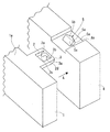
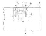
図1に示すように、一方の樹脂部品1の上面1aには、係合部としての係合孔2を有する板状の係合爪3が一体に形成されており、他方の樹脂部品4の上面4aには、前記係合孔2に係合される係合突起5が一体に形成されている。なお、樹脂部品1の外面には、係合孔2を有する係合爪3が複数箇所に形成されており、樹脂部品4の外面には、前記各係合爪3(係合孔2)の位置に合わせて複数の係合突起5が形成されている。前記した樹脂部品1と樹脂部品4は、例えば、車両のインストルメントパネルなどに組み付けられる各種装置等の筐体である。
As shown in FIG. 1, a plate-
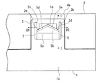
弾性を有する係合爪3の先端側の先端下面3aは、後方側に向けて傾斜している。係合孔2の先端側の両側には、係合爪3の先端側に向けてスリット状の溝部2a,2bがそれぞれ形成されており、各溝部2a,2bの内側には、係合爪3の基端側に向けて突起した凸部2c,2dがそれぞれ一体に形成されている。凸部2c,2dは、樹脂部品1の左右方向に弾性変形自在である。
The tip
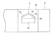
図1、図2に示すように、係合突起5の垂直壁状の係合面5aは、中央部が前方に突出してその両側が斜面状に形成されている。係合突起5の上面5bは、両側面が短い五角形状に形成され、係合突起5の背面5cは、後方側(上面5bと反対側)に向けて傾斜している。また、係合突起5の係合面5aと上面5bの間には、係合面5a側に下がる傾斜面5d,5eが形成されている。
As shown in FIGS. 1 and 2, the vertical wall-
次に、前記した本実施形態に係る部品固定構造について説明する。 Next, the component fixing structure according to the above-described embodiment will be described.
図1に示したように、係合爪3と係合突起5の位置を合わせて、係合突起5の背面5c側から一方の樹脂部品1を他方の樹脂部品4に向けて矢印A方向に移動させることにより、係合爪3の傾斜した先端下面3aが係合突起5の傾斜した背面5c上を摺動しながら移動する。
As shown in FIG. 1, the
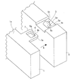
そして、樹脂部品1を更に矢印A方向に移動させると、図3に示すように、係合爪3の先端下面3aが係合突起5の背面5cを乗り越えて上面5bと傾斜面5d,5e上を摺動しながら移動して、係合爪3に設けた係合孔2が係合突起5に係合する。
When the resin component 1 is further moved in the direction of arrow A, as shown in FIG. 3, the
即ち、図3、図4に示すように、係合突起5の係合面5aの斜面状の両端側が係合孔2の凸部2c,2dに圧接することにより、係合孔2が係合突起5に係合して、一方の樹脂部品1と他方の樹脂部品4が固定される。この際、係合突起5の係合面5aの斜面状の両端側が、係合孔2の凸部2c,2dの各先端内側に圧接することにより、凸部2c,2dはそれぞれ外側方向(矢印B1,B2方向)に弾性変形する。
That is, as shown in FIGS. 3 and 4, the both ends of the inclined surface of the
これにより、樹脂成形される係合孔2(係合爪3)と係合突起5に寸法公差があっても、係合爪3に設けた係合孔2が係合突起5に係合されたときに、前記凸部2c,2dの弾性変形によって係合孔2(係合爪3)と係合突起5の寸法公差を吸収することができるので、ガタツキの発生を防止することができる。
As a result, even if there is a dimensional tolerance between the resin-molded engagement hole 2 (engagement claw 3) and the
また、係合突起5の前面5aと上面5bの間に、前面5a側に下がる傾斜面5d,5eを形成しているので、係合爪3に設けた係合孔2(凸部2c,2d)を係合突起5の前端面5aにスムーズに押し込んで係合させることができる。
Moreover, since the
なお、前記した係合孔2と係合突起5の係合状態を解除する場合は、係合爪3の先端下面3aを上方に持ち上げて係合爪3を上方に弾性変形させることにより、係合孔2と係合突起5の係合状態を解除することができる。
〈実施形態2〉
本発明の実施形態2では、図5に示すように、先端側に凹状に開口した係合部6を有する板状の係合爪7が一体に形成された一方の樹脂部品1を備えている。なお、他方の樹脂部品4の上面に一体に形成された係合突起5の形状は、前記実施形態1と同様である。
When the engagement state between the
<
In the second embodiment of the present invention, as shown in FIG. 5, one resin component 1 is integrally formed with a plate-
係合部6の先端部の両側には、内側に向けて対向するようにして突起した弾性変形自在な凸部6a,6bがそれぞれ形成されている。なお、係合爪7の先端側の先端下面7aは、後方側に向けて傾斜している。
On both sides of the front end portion of the
次に、本実施形態に係る部品固定構造について説明する。 Next, the component fixing structure according to the present embodiment will be described.
図5に示したように、係合爪7と係合突起5の位置を合わせて、係合突起5の背面5c側から一方の樹脂部品1を他方の樹脂部品4に向けて矢印A方向に移動させることにより、係合爪7の傾斜した先端下面7aが係合突起5の傾斜した背面5c上を摺動しながら移動する。
As shown in FIG. 5, the positions of the
そして、樹脂部品1を更に矢印A方向に移動させると、図6に示すように、係合爪7の先端下面7aが係合突起5の背面5c上を乗り越えて上面5bと傾斜面5d,5e上を摺動しながら移動して、係合爪7に設けた係合部6が係合突起5に係合する。
When the resin component 1 is further moved in the direction of arrow A, as shown in FIG. 6, the tip
即ち、図6に示すように、係合突起5の係合面5aの斜面状の両端側が係合部6の凸部6a,6bに圧接することにより、係合部6が係合突起5に係合して、一方の樹脂部品1と他方の樹脂部品4が固定される。この際、係合突起5の係合面5aの斜面状の両端側が、係合部6の凸部6a,6bの各先端内側に圧接することにより、凸部6a,6bはそれぞれ前方方向(矢印C方向)に弾性変形する。
That is, as shown in FIG. 6, the both ends of the inclined surface of the
これにより、樹脂成形される係合部6(係合爪7)と係合突起5に寸法公差があっても、係合爪7に設けた係合部6が係合突起5に係合されたときに、前記凸部6a,6bの弾性変形によって係合部6(係合爪7)と係合突起5の寸法公差を吸収することができるので、ガタツキの発生を防止することができる。
〈実施形態3〉
図7は、本発明の実施形態3に係る部品固定構造によって固定される樹脂部品の要部を示す概略斜視図である。
Thereby, even if there is a dimensional tolerance between the engaging portion 6 (engaging claw 7) and the
<
FIG. 7 is a schematic perspective view showing a main part of a resin component fixed by the component fixing structure according to
図7に示すように、一方の樹脂部品1の上面1aには、係合孔10を有する板状の係合爪11とこの係合爪11の両側に弾性変形自在な突起片12a,12bが一体に形成されており、他方の樹脂部品4の上面4aには、前記係合孔10に係合される係合突起13と前記突起片12a,12bが圧接される突起部14a,14bが一体に形成されている。なお、係合爪11と突起片12a,12bは、それらの厚みに対応して一体に形成された段部11aを介して樹脂部品1の上面1aから突出している。
As shown in FIG. 7, a plate-
なお、樹脂部品1の外面には、係合孔10を有する係合爪11、および突起片12a,12bが複数箇所に形成されており、また、樹脂部品4の外面には、前記各係合爪11(係合孔10)の位置に合わせて複数の係合突起13が形成され、更に、各突起片12a,12bの位置に合わせて複数の突起部14a,14bが形成されている。
Note that the outer surface of the resin component 1 is formed with an engaging
弾性を有する係合爪11の先端側の先端下面11bは、後方側に向けて傾斜している。突起片12a,12bの外側は内側に向けて少し湾曲しており、一方の樹脂部品1を他方の樹脂部品4側に移動させたときに、突起片12a,12bの外側が突起部14a,14bの内側に入るようにして圧接する。係合突起13の係合面13aは垂直壁状に形成されており、係合突起13の背面13bは後方に向けて傾斜している。
The tip
次に、前記した本実施形態に係る部品固定構造について説明する。 Next, the component fixing structure according to the above-described embodiment will be described.
図7に示したように、係合爪11と係合突起13の位置を合わせて、係合突起13の背面13b側から一方の樹脂部品1を他方の樹脂部品4に向けて矢印A方向に移動させることにより、係合爪11の傾斜した先端下面11baが係合突起13の傾斜した背面13b上を摺動しながら移動する。
As shown in FIG. 7, the positions of the engaging
そして、樹脂部品1を更に矢印A方向に移動させると、図8に示すように、係合突起13の上面13c上を摺動しながら移動して、係合爪11に設けた係合孔10が係合突起13の係合面13aに係合して、一方の樹脂部品1と他方の樹脂部品4が固定される。この際、突起片12a,12bの外側が突起部14a,14bの角部に圧接するすることにより、突起片12a,12bはそれぞれ内側方向(矢印C1,C2方向)に弾性変形する。
When the resin component 1 is further moved in the direction of arrow A, as shown in FIG. 8, the resin component 1 moves while sliding on the
これにより、樹脂成形される係合孔10(係合爪11)と係合突起13に寸法公差があっても、係合爪11に設けた係合孔10が係合突起13の係合面13aに係合されたときに、突起部14a,14bの角部に圧接する突起片12a,12bの弾性変形によって係合孔10(係合爪11)と係合突起13の寸法公差を吸収することができるので、ガタツキの発生を防止することができる。
。
Thereby, even if there is a dimensional tolerance between the engagement hole 10 (engagement claw 11) and the
.
1 一方の樹脂部品
2、10 係合孔(係合部)
2c,2d、6a,6b 凸部
3、7、11 係合爪
4 他方の樹脂部品
5、13 係合突起
5a 係合面
6 係合部
12a,12b 突起片
14a,14b 突起部
1 One
2c, 2d, 6a,
Claims (1)
前記係合部に弾性変形自在な一対の突起状の凸部を一体に形成するとともに、前記係合突起の係合面を、中央部が突出してその両側に向けて傾斜するような斜面状に形成し、前記係合部に前記係合突起を係合したときに、前記各凸部を前記係合突起の斜面状の係合面に圧接させる、
ことを特徴とする部品固定構造。
One engaging resin claw having an engaging part that is open, and the other resin part integrally forming an engaging projection that engages with the engaging part, A part fixing structure for engaging the engaging surface of the engaging protrusion with the part and fixing the one resin part and the other resin part;
A pair of elastically deformable protrusions are formed integrally with the engaging portion, and the engaging surface of the engaging protrusion is formed in a slope shape so that the central portion protrudes and inclines toward both sides. Forming and engaging each of the convex portions with the slope-like engaging surface of the engaging protrusion when the engaging protrusion is engaged with the engaging portion,
A component fixing structure characterized by that.
Priority Applications (1)
| Application Number | Priority Date | Filing Date | Title |
|---|---|---|---|
| JP2005351664A JP2007155014A (en) | 2005-12-06 | 2005-12-06 | Component fixing structure |
Applications Claiming Priority (1)
| Application Number | Priority Date | Filing Date | Title |
|---|---|---|---|
| JP2005351664A JP2007155014A (en) | 2005-12-06 | 2005-12-06 | Component fixing structure |
Publications (1)
| Publication Number | Publication Date |
|---|---|
| JP2007155014A true JP2007155014A (en) | 2007-06-21 |
Family
ID=38239650
Family Applications (1)
| Application Number | Title | Priority Date | Filing Date |
|---|---|---|---|
| JP2005351664A Pending JP2007155014A (en) | 2005-12-06 | 2005-12-06 | Component fixing structure |
Country Status (1)
| Country | Link |
|---|---|
| JP (1) | JP2007155014A (en) |
Cited By (6)
| Publication number | Priority date | Publication date | Assignee | Title |
|---|---|---|---|---|
| KR101057039B1 (en) * | 2008-12-23 | 2011-08-16 | 콘티넨탈 오토모티브 일렉트로닉스 유한회사 | Noise reduction device of vehicle cluster |
| KR101327279B1 (en) * | 2011-12-13 | 2013-11-08 | 콘티넨탈 오토모티브 일렉트로닉스 유한회사 | Lighting device of cluster panel for vehicle |
| KR20160133499A (en) * | 2014-03-18 | 2016-11-22 | 가부시키가이샤 패디 필드 | Assemblable structure |
| KR101845764B1 (en) * | 2012-07-26 | 2018-04-05 | 현대자동차주식회사 | Structure of door-curtain for vehicle |
| JP2018112111A (en) * | 2017-01-11 | 2018-07-19 | 愛三工業株式会社 | Evaporated fuel treatment device |
| JP7454994B2 (en) | 2020-05-01 | 2024-03-25 | 未来工業株式会社 | protective cover |
-
2005
- 2005-12-06 JP JP2005351664A patent/JP2007155014A/en active Pending
Cited By (7)
| Publication number | Priority date | Publication date | Assignee | Title |
|---|---|---|---|---|
| KR101057039B1 (en) * | 2008-12-23 | 2011-08-16 | 콘티넨탈 오토모티브 일렉트로닉스 유한회사 | Noise reduction device of vehicle cluster |
| KR101327279B1 (en) * | 2011-12-13 | 2013-11-08 | 콘티넨탈 오토모티브 일렉트로닉스 유한회사 | Lighting device of cluster panel for vehicle |
| KR101845764B1 (en) * | 2012-07-26 | 2018-04-05 | 현대자동차주식회사 | Structure of door-curtain for vehicle |
| KR20160133499A (en) * | 2014-03-18 | 2016-11-22 | 가부시키가이샤 패디 필드 | Assemblable structure |
| KR102397621B1 (en) * | 2014-03-18 | 2022-05-16 | 가부시키가이샤 패디 필드 | Assemblable structure |
| JP2018112111A (en) * | 2017-01-11 | 2018-07-19 | 愛三工業株式会社 | Evaporated fuel treatment device |
| JP7454994B2 (en) | 2020-05-01 | 2024-03-25 | 未来工業株式会社 | protective cover |
Similar Documents
| Publication | Publication Date | Title |
|---|---|---|
| JP2007165765A (en) | Lock structure of box | |
| JP3715235B2 (en) | Vehicle roof molding | |
| JP2007155014A (en) | Component fixing structure | |
| JP5219696B2 (en) | connector | |
| JPH10199622A (en) | Double lock for connector | |
| JP2006228558A (en) | Connector | |
| JP2006234035A (en) | Fitting structure | |
| JP2010112508A (en) | Fixture of intrusion type | |
| JP2006038157A (en) | Member fitting structure | |
| JPWO2015008551A1 (en) | Reinforcing leaf spring for plastic clips | |
| JPH11287221A (en) | Clip | |
| JP2011235603A (en) | Coupled stamper | |
| JP2006262667A (en) | Locking structure of wire harness protector | |
| JP2010178474A (en) | Electric component | |
| JP5138450B2 (en) | Two-part assembly structure | |
| JP2001057269A (en) | Connector | |
| JP4543285B2 (en) | Mall material fixture | |
| JP2005347074A (en) | Switch mounting structure of vehicle | |
| JP2000245032A (en) | Lock structure for vehicle part and electric junction box | |
| JP2007074808A (en) | Attachment element | |
| JP2016061099A (en) | Panel edge material, panel installing structure and structure assembling method | |
| JP2019054094A (en) | Housing connection structure | |
| JP5448633B2 (en) | connector | |
| JP2008120321A (en) | Bumper installing structure of vehicle | |
| JP4200898B2 (en) | Engaging claw |