JP2007147746A - Electrophotographic photoreceptor, process cartridge, image forming device, and method for manufacturing electrophotographic photoreceptor - Google Patents
Electrophotographic photoreceptor, process cartridge, image forming device, and method for manufacturing electrophotographic photoreceptor Download PDFInfo
- Publication number
- JP2007147746A JP2007147746A JP2005339007A JP2005339007A JP2007147746A JP 2007147746 A JP2007147746 A JP 2007147746A JP 2005339007 A JP2005339007 A JP 2005339007A JP 2005339007 A JP2005339007 A JP 2005339007A JP 2007147746 A JP2007147746 A JP 2007147746A
- Authority
- JP
- Japan
- Prior art keywords
- zinc oxide
- oxide particles
- photosensitive member
- electrophotographic photoreceptor
- electrophotographic
- Prior art date
- Legal status (The legal status is an assumption and is not a legal conclusion. Google has not performed a legal analysis and makes no representation as to the accuracy of the status listed.)
- Pending
Links
Images


Abstract
Description
本発明は、電子写真感光体、プロセスカートリッジおよび画像形成装置、並びに、電子写真感光体の製造方法に関する。 The present invention relates to an electrophotographic photosensitive member, a process cartridge, an image forming apparatus, and a method for manufacturing an electrophotographic photosensitive member.
電子写真装置は、高速でかつ高印字の品質が得られる装置であり、複写機やレーザービームプリンター等として利用されている。電子写真装置に搭載される電子写真感光体(以下、単に「感光体」という場合もある)としては、有機光導電性材料を用いた有機感光体が主流となっており、その構成も感光層が電荷発生層と電荷輸送層とを備える機能分離型へと変遷し性能が向上している。また、これらの機能層以外に、導電性支持体と感光層との間に下引層(「中間層」ともいう)が設けられたもの、最外層として保護層を備えるものなども知られている。 An electrophotographic apparatus is an apparatus capable of obtaining high-quality printing at high speed, and is used as a copying machine, a laser beam printer, or the like. As an electrophotographic photoreceptor (hereinafter sometimes simply referred to as “photoreceptor”) mounted in an electrophotographic apparatus, an organic photoreceptor using an organic photoconductive material has become the mainstream, and the configuration thereof is also a photosensitive layer. Has changed to a function separation type comprising a charge generation layer and a charge transport layer, and the performance has been improved. In addition to these functional layers, those having an undercoat layer (also referred to as “intermediate layer”) between the conductive support and the photosensitive layer, and those having a protective layer as the outermost layer are also known. Yes.
上記の機能層のうち、下引層や保護層などには、感光体の電気特性を向上させる観点から金属酸化物粒子を含有させることが多い。金属酸化物粒子の中でも酸化亜鉛粒子は、半導体としての電気特性や仕事関数が感光体材料として好適であること、感光体の電気特性に影響を及ぼす粒径を制御しやすいこと等の利点を有しており、例えば、酸化亜鉛粒子を含む下引層(例えば、特許文献1及び2を参照)を設けることによって、電子写真感光体の繰返し電位特性や環境安定性の改善効果が期待できる。また、酸化亜鉛粒子は他の金属酸化物に比べて安全性及びコスト的に優れている点でも利用価値の高い材料である。
Of the functional layers described above, the undercoat layer and the protective layer often contain metal oxide particles from the viewpoint of improving the electrical characteristics of the photoreceptor. Among metal oxide particles, zinc oxide particles have advantages such as electrical characteristics and work function as a semiconductor suitable as a photoreceptor material, and easy control of the particle size that affects the electrical characteristics of the photoreceptor. For example, the provision of an undercoat layer containing zinc oxide particles (see, for example,
しかし、上記特許文献1及び2に記載の下引層を有する感光体は、以下の点で改善の余地がある。
However, the photoreceptor having the undercoat layer described in
すなわち、本発明者らの検討によると、酸化亜鉛粒子を含む感光体は、製造ロットの違いによって繰返し使用時に画像の低濃度化や露光部の画像が白く抜けるネガメモリ等の画質欠陥が生じる場合があることが判明している。 That is, according to the study by the present inventors, the photoreceptor containing zinc oxide particles may cause image quality defects such as negative memory in which the density of the image is reduced or the image of the exposed portion is whitened during repeated use due to the difference in production lots. It turns out that there is.
上記画質欠陥の生じる虞のあるロットは、製造された感光体について環境加速試験等(例えば、帯電−露光繰り返し試験機による電位測定など)を実施することにより特定することが可能な場合もあるが、このような品質管理方法のみでは製品の歩留まりを十分に維持することは困難である。そのため、実生産上、上記の画質欠陥を十分抑制できる感光体を製造することが重要となる。 The lot where image quality defects may occur may be identified by performing an environmental acceleration test or the like (for example, potential measurement using a charge-exposure repeated test machine) on the manufactured photoreceptor. Therefore, it is difficult to sufficiently maintain the product yield only by such a quality control method. Therefore, in actual production, it is important to manufacture a photoconductor that can sufficiently suppress the image quality defects.
本発明は、上記実情に鑑みてなされたものであり、画像の低濃度化及びネガメモリの発生を十分に抑制可能であり、繰返し電位特性及び環境安定性に優れた電子写真感光体、かかる電子写真感光体の製造方法、並びに、電子写真装置及びプロセスカートリッジを提供することを目的とする。 The present invention has been made in view of the above circumstances, and can sufficiently reduce image density reduction and negative memory generation, and is excellent in repetitive potential characteristics and environmental stability. It is an object of the present invention to provide a method for manufacturing a photoreceptor, an electrophotographic apparatus, and a process cartridge.
本発明者は、上記目的を達成すべく鋭意研究した結果、先ず、酸化亜鉛粒子を含む感光体の電子写真特性は、酸化亜鉛粒子の製造ロットの違いによって異なるとの知見を得た。更に、酸化亜鉛粒子の一般的性状(体積平均粒径など)は同一であっても上記画質欠陥が発生することを見出し、その一因が酸化亜鉛粒子から溶出するイオン性不純物にあることの知見を得た。そして、かかる知見に基づいて更に研究を重ねた結果、イオン性不純物の溶出量が特定の値以下である酸化亜鉛粒子を下引層の構成材料として用いることにより上記画質欠陥の発生を長期に亘って抑制できることを見出し、本発明を完成するに至った。 As a result of intensive studies to achieve the above object, the present inventor has first obtained the knowledge that the electrophotographic characteristics of a photoreceptor containing zinc oxide particles differ depending on the production lot of zinc oxide particles. Furthermore, even when the general properties (volume average particle size, etc.) of zinc oxide particles are the same, it has been found that the above-mentioned image quality defects occur, and the knowledge that the cause is ionic impurities eluted from the zinc oxide particles Got. As a result of further research based on such knowledge, the use of zinc oxide particles whose ionic impurity elution amount is not more than a specific value as a constituent material of the undercoat layer causes the occurrence of the image quality defect over a long period of time. As a result, the present invention has been completed.
すなわち、本発明の電子写真感光体は、酸化亜鉛粒子を含有する機能層を備える電子写真感光体であって、機能層が、下記式(1)を満たす酸化亜鉛粒子または当該酸化亜鉛粒子を表面処理したものを含有するものであることを特徴とする。
A≦50 …(1)
ここで、式(1)中、Aは、酸化亜鉛粒子を濃度が2.5質量%になるように電気伝導度1.0μS/cm以下の純水と混合したときの混合液の25℃における電気伝導度(μS/cm)を示す。
That is, the electrophotographic photoreceptor of the present invention is an electrophotographic photoreceptor provided with a functional layer containing zinc oxide particles, and the functional layer has zinc oxide particles satisfying the following formula (1) or the zinc oxide particles on the surface. It is characterized by containing what was processed.
A ≦ 50 (1)
Here, in the formula (1), A is a mixture solution at 25 ° C. when zinc oxide particles are mixed with pure water having an electric conductivity of 1.0 μS / cm or less so that the concentration becomes 2.5 mass%. Electric conductivity (μS / cm) is shown.
上記本発明の電子写真感光体によれば、繰返し使用による画像の低濃度化及びネガメモリの発生を十分に抑制することができ、酸化亜鉛粒子による優れた電気特性の改善効果を有効に発揮させることが可能となる。そして、繰返し電位特性及び環境安定性に優れた本発明の感光体を画像形成装置に適用することにより高画質化を高水準で達成できる。 According to the electrophotographic photosensitive member of the present invention, it is possible to sufficiently suppress the reduction in image density and the occurrence of negative memory due to repeated use, and to effectively exhibit the excellent electrical property improvement effect due to the zinc oxide particles. Is possible. Further, by applying the photoreceptor of the present invention excellent in repetitive potential characteristics and environmental stability to an image forming apparatus, high image quality can be achieved at a high level.
本発明により上記の効果が奏される理由としては、本発明者らは以下のとおり推察する。すなわち、電子写真感光体の構成材料として含有される酸化亜鉛粒子は、機能層の成膜性及び結着樹脂中に分散したときの適切な導電性を確保する観点から、一次粒径が300nm以下のものが用いられ、このような酸化亜鉛粒子は一般に塩基性炭酸亜鉛を経由する湿式法により製造される。そして、塩基性炭酸亜鉛の製造過程において混入する塩化ナトリウム、塩化カルシウム、硫酸塩及び炭酸塩などのイオン性不純物が、感光体の電子写真特性の安定性に影響しているものと考えられる。より具体的には、上記従来の感光体では、上記のイオン性不純物若しくは当該不純物から発生したイオンが機能層中に局在準位を形成してキャリアを捕捉することや、機能層が導電性支持体と隣接して設けられた場合には不純物が支持体を腐食して支持体と機能層との界面に半導電性若しくは絶縁性被膜が形成されてしまうことにより、繰返し使用による残留電位の上昇や帯電電位の低下が引き起こされているものと考えられる。これに対して、本発明の感光体では酸化亜鉛粒子から溶出するイオン性不純物の量が特定の値に制限されていることで、機能層に酸化亜鉛粒子を十分に配合させた場合であっても上述のキャリア捕捉や被膜形成を防止することができ、その結果、上記効果が得られたものと推察される。また、本発明者らは、感光体の電子写真特性に悪影響を及ぼすイオンとしては、塩素イオンのみならずナトリウムイオン等も電子を捕捉して電位特性を変動させる要因であると考えている。また、特に高温高湿の環境下においては吸湿により酸化亜鉛粒子に含まれるイオン性不純物のほとんどが機能層の導電性に変化をもたらすと考えられる。本発明によれば、酸化亜鉛粒子に含まれるイオン性不純物の総量を規定することで上記の変動も有効に防止できることから、繰返し電位特性及び環境安定性に優れた電子写真感光体の実現が可能となったとも本発明者らは推察する。 The reason why the above-described effects are achieved by the present invention is presumed as follows. That is, the zinc oxide particles contained as the constituent material of the electrophotographic photosensitive member have a primary particle size of 300 nm or less from the viewpoint of ensuring the film formability of the functional layer and appropriate conductivity when dispersed in the binder resin. Such zinc oxide particles are generally produced by a wet process via basic zinc carbonate. It is considered that ionic impurities such as sodium chloride, calcium chloride, sulfate and carbonate mixed in the process of producing basic zinc carbonate influence the stability of the electrophotographic characteristics of the photoreceptor. More specifically, in the conventional photoreceptor, the ionic impurities or ions generated from the impurities form localized levels in the functional layer to trap carriers, or the functional layer is conductive. When it is provided adjacent to the support, impurities corrode the support and a semiconductive or insulating film is formed at the interface between the support and the functional layer. It is thought that the rise and the decrease of the charged potential are caused. On the other hand, in the photoconductor of the present invention, the amount of ionic impurities eluted from the zinc oxide particles is limited to a specific value, so that the zinc oxide particles are sufficiently mixed in the functional layer. Can also prevent the above-described carrier capture and film formation, and as a result, it is presumed that the above-described effects were obtained. Further, the present inventors consider that ions that adversely affect the electrophotographic characteristics of the photoconductor are not only chlorine ions but also sodium ions and the like are factors that cause the potential characteristics to fluctuate by capturing electrons. In particular, in a high temperature and high humidity environment, it is considered that most of the ionic impurities contained in the zinc oxide particles change the conductivity of the functional layer due to moisture absorption. According to the present invention, since the above fluctuation can be effectively prevented by defining the total amount of ionic impurities contained in the zinc oxide particles, an electrophotographic photoreceptor excellent in repetitive potential characteristics and environmental stability can be realized. The present inventors infer that it has become.
本発明の電子写真感光体においては、上記機能層が、塩基性炭酸亜鉛粒子を準備する準備工程と、塩基性炭酸亜鉛粒子を純水に接触させる純水接触工程と、純水に接触させた塩基性炭酸亜鉛粒子を培焼して酸化亜鉛粒子を得る培焼工程とを経て得られる上記式(1)を満たす酸化亜鉛粒子または当該酸化亜鉛粒子を表面処理したものを含むものであることが好ましい。これにより、電子写真感光体の残留電位の上昇及びネガメモリの発生を抑制する効果を更に高めることができ、繰返し電位特性及び環境安定性に優れた感光体がより確実に実現可能となる。 In the electrophotographic photosensitive member of the present invention, the functional layer is brought into contact with pure water, a preparation step of preparing basic zinc carbonate particles, a pure water contact step of bringing basic zinc carbonate particles into contact with pure water, and pure water. It is preferable to include zinc oxide particles that satisfy the above formula (1) obtained by culturing basic zinc carbonate particles and obtaining zinc oxide particles, or those obtained by surface treatment of the zinc oxide particles. As a result, the effect of suppressing the increase in the residual potential of the electrophotographic photosensitive member and the occurrence of negative memory can be further enhanced, and a photosensitive member excellent in repetitive potential characteristics and environmental stability can be more reliably realized.
なお、上記の効果は、従来の電子写真感光体において画質欠陥が発生する一因が酸化亜鉛粒子から溶出するイオン性不純物にあり、かかる不純物濃度を低減することによってイオン性不純物による電子写真特性への悪影響を抑制できるという本発明者らの知見に基づくものであり、塩基性炭酸亜鉛粒子を純水に接触させることによって最終的に得られる酸化亜鉛粒子のイオン性不純物含有量を極めて低い水準まで低減できることにより奏されたものと考えられる。 The above effect is due to the ionic impurities eluted from the zinc oxide particles that cause image quality defects in the conventional electrophotographic photosensitive member. By reducing the impurity concentration, electrophotographic characteristics due to ionic impurities can be obtained. The ionic impurity content of the zinc oxide particles finally obtained by bringing the basic zinc carbonate particles into contact with pure water is extremely low. It is thought that it was played by being able to reduce.
また、上記酸化亜鉛粒子はその製造過程において画質欠陥に影響を及ぼすイオン性不純物が効率よく除去されることから、かかる酸化亜鉛粒子を含む上記感光体は優れたコストパフォーマンスを発揮し得る。 In addition, since the ionic impurities affecting the image quality defect are efficiently removed in the manufacturing process of the zinc oxide particles, the photoconductor including the zinc oxide particles can exhibit excellent cost performance.
上記の効果をより確実に得る観点から、上記純水は、25℃における電気伝導度が1.0μS/cm以下であるものが好ましい。 From the viewpoint of obtaining the above effect more reliably, the pure water preferably has an electrical conductivity at 25 ° C. of 1.0 μS / cm or less.
本発明の電子写真感光体においては、上記機能層が、酸化亜鉛粒子を準備する準備工程と、酸化亜鉛粒子を水に接触させる水接触工程とを経て得られる上記式(1)を満たす酸化亜鉛粒子または当該酸化亜鉛粒子を表面処理したものを含むものであることが好ましい。 In the electrophotographic photoreceptor of the present invention, the functional layer has zinc oxide satisfying the above formula (1) obtained through a preparation step of preparing zinc oxide particles and a water contact step of bringing the zinc oxide particles into contact with water. It is preferable to include particles or those obtained by surface-treating the zinc oxide particles.
ここで、上記「水」とは、水道水、RO処理水、蒸留水又は純水のいずれかを指す。 Here, the “water” refers to any of tap water, RO-treated water, distilled water, or pure water.
上記機能層を備える感光体によれば、より安価な手段により得られる酸化亜鉛粒子を用いて上記画質欠陥の発生を十分抑制できることから、生産性と電気特性向上効果とを良好にバランスさせることが可能となる。このような効果が得られる理由としては、イオン性不純物は酸化亜鉛粒子表面に濃縮されて存在すると考えられ、酸化亜鉛粒子の準備工程後に水接触工程を実施することで酸化亜鉛粒子からイオン性不純物を効果的に除去できるためと推察される。 According to the photoreceptor provided with the functional layer, since the occurrence of the image quality defect can be sufficiently suppressed by using zinc oxide particles obtained by a cheaper means, it is possible to satisfactorily balance the productivity and the electrical property improvement effect. It becomes possible. The reason why such an effect is obtained is that the ionic impurities are considered to be concentrated on the surface of the zinc oxide particles, and the ionic impurities are removed from the zinc oxide particles by performing a water contact step after the zinc oxide particle preparation step. It is inferred that it can be effectively removed.
画質欠陥の発生をより確実に抑制する観点から、上記水は、25℃における電気伝導度が250μS/cm以下であるものが好ましい。 From the viewpoint of more reliably suppressing the occurrence of image quality defects, the water preferably has an electric conductivity at 25 ° C. of 250 μS / cm or less.
また、本発明の電子写真感光体は、導電性支持体と該導電性支持体上に設けられた感光層とを備える電子写真感光体であって、上記機能層が導電性支持体と感光層との間に配置されていることが好ましい。 The electrophotographic photoreceptor of the present invention is an electrophotographic photoreceptor comprising a conductive support and a photosensitive layer provided on the conductive support, wherein the functional layer is a conductive support and a photosensitive layer. It is preferable to arrange | position between.
上記のように本発明に係る機能層を下引層として設けた場合、従来の感光体に比べてより一層の電気特性の向上を図ることが可能となる。上述したように、本発明によれば、下引層に酸化亜鉛粒子を十分配合した場合であっても酸化亜鉛粒子由来のイオン性不純物が局在準位を形成してキャリアを捕捉することやイオン性不純物が支持体表面を腐食して支持体と下引層との界面に半導電性又は絶縁性被膜が形成されてしまうことを十分防止できると考えられ、これにより、露光部電位の上昇、繰返し使用による残留電位の上昇及び帯電電位の低下を十分抑制できるためと推察される。 As described above, when the functional layer according to the present invention is provided as the undercoat layer, it is possible to further improve the electric characteristics as compared with the conventional photoreceptor. As described above, according to the present invention, even when zinc oxide particles are sufficiently blended in the undercoat layer, ionic impurities derived from zinc oxide particles form localized levels and trap carriers. It is thought that it is possible to sufficiently prevent the ionic impurities from corroding the support surface and forming a semiconductive or insulating film at the interface between the support and the undercoat layer. It is presumed that the increase in the residual potential and the decrease in the charging potential due to repeated use can be sufficiently suppressed.
本発明の電子写真感光体においては、上記機能層が、上記酸化亜鉛粒子をアミノ基を有するシランカップリング剤で表面処理したものを含むことが好ましい。これにより、繰返し使用による画像の低濃度化及びネガメモリの発生を抑制する効果を十分維持しつつ、帯電電位の低下を防止する効果を飛躍的に高めることが可能となる。このような効果が得られる理由としては、本発明者らは以下のとおり推察する。 In the electrophotographic photoreceptor of the present invention, it is preferable that the functional layer includes a surface treatment of the zinc oxide particles with a silane coupling agent having an amino group. As a result, it is possible to drastically enhance the effect of preventing a decrease in charging potential while sufficiently maintaining the effect of suppressing image density reduction and negative memory generation due to repeated use. As the reason why such an effect is obtained, the present inventors infer as follows.
すなわち、酸化亜鉛粒子が上記式(1)を満たすものであることにより、上記シランカップリング剤によって表面処理した場合、シランカップリング剤の酸化亜鉛表面への反応率が向上し、酸化亜鉛粒子間又は酸化亜鉛粒子と機能層との界面において効果的な整流作用を発現させることが可能になったものと考えられる。その結果、帯電電位の低下を防止する効果が高度に高められたものと推察される。 That is, when the zinc oxide particles satisfy the above formula (1), when the surface treatment is performed with the silane coupling agent, the reaction rate of the silane coupling agent to the zinc oxide surface is improved, and between the zinc oxide particles Alternatively, it is considered that an effective rectifying action can be expressed at the interface between the zinc oxide particles and the functional layer. As a result, it is presumed that the effect of preventing the decrease in the charging potential is highly enhanced.
また、本発明は、酸化亜鉛粒子を濃度が2.5質量%になるように電気伝導度1.0μS/cm以下の純水と混合し混合液を調整する混合液調整工程と、混合液の25℃における電気伝導度を測定する測定工程と、測定工程において得られた電気伝導度の測定値が50μS/cm以下であるか否かを判別する工程とを備える酸化亜鉛粒子の品質検査方法において電気伝導度の測定値が所定条件を満たすものと判断された酸化亜鉛粒子または当該酸化亜鉛粒子を表面処理したものを準備する準備工程と、機能層が形成されて電子写真感光体となるべき被処理体を準備する被処理体準備工程と、上記酸化亜鉛粒子または上記酸化亜鉛粒子を表面処理したものを含む塗布液を調整し、当該塗布液を被処理体上に塗布して、乾燥し機能層を形成する機能層形成工程とを備えることを特徴とする電子写真感光体の製造方法を提供する。 The present invention also includes a liquid mixture adjusting step of adjusting the liquid mixture by mixing zinc oxide particles with pure water having an electric conductivity of 1.0 μS / cm or less so that the concentration is 2.5% by mass; In a quality inspection method for zinc oxide particles, comprising: a measurement step of measuring electrical conductivity at 25 ° C .; and a step of determining whether or not the measured value of electrical conductivity obtained in the measurement step is 50 μS / cm or less. A preparatory step of preparing zinc oxide particles whose surface conductivity is determined to satisfy a predetermined condition, or a surface treatment of the zinc oxide particles; A processing target preparation step for preparing a processing body and a coating liquid containing the zinc oxide particles or the surface-treated zinc oxide particles are prepared, and the coating liquid is applied onto the processing target and dried. Ability to form layers And a layer forming step. A method for producing an electrophotographic photosensitive member is provided.
ここで、上記被処理体は、機能層が形成されて電子写真感光体となるものであり、目的の電子写真感光体から機能層と機能層の形成後に形成される層を除いた構成を有するものである。機能層が最後に形成される場合は、目的の電子写真感光体から機能層を除いた構成を有するものである。 Here, the object to be processed is an electrophotographic photosensitive member in which a functional layer is formed, and has a configuration in which a functional layer and a layer formed after formation of the functional layer are excluded from the target electrophotographic photosensitive member. Is. When the functional layer is formed last, the functional layer is removed from the target electrophotographic photosensitive member.
本発明の電子写真感光体の製造方法によれば、繰り返し使用による画像の低濃度化及びネガメモリの発生を十分に抑制可能な本発明の電子写真感光体を有効に得ることができる。 According to the method for producing an electrophotographic photosensitive member of the present invention, it is possible to effectively obtain the electrophotographic photosensitive member of the present invention that can sufficiently suppress image density reduction and negative memory generation by repeated use.
本発明の電子写真感光体の製造方法において、上記酸化亜鉛粒子が、塩基性炭酸亜鉛粒子を準備する準備工程と、塩基性炭酸亜鉛粒子を純水に接触させる純水接触工程と、純水に接触させた塩基性炭酸亜鉛粒子を培焼して酸化亜鉛粒子を得る培焼工程とを含む酸化亜鉛粒子の製造方法により得られたものであることが好ましい。これにより、製造される電子写真感光体の残留電位の上昇及びネガメモリの発生を抑制する効果を更に高めることが可能となる。 In the method for producing an electrophotographic photosensitive member of the present invention, the zinc oxide particles are prepared by preparing a basic zinc carbonate particles, a pure water contact step of bringing the basic zinc carbonate particles into contact with pure water, and pure water. It is preferable to be obtained by a method for producing zinc oxide particles, which comprises culturing the contacted basic zinc carbonate particles to obtain zinc oxide particles. As a result, it is possible to further enhance the effect of suppressing the increase in the residual potential of the electrophotographic photoreceptor to be manufactured and the generation of negative memory.
また、生産性と電気特性向上効果とを良好にバランスさせる観点からは、本発明の電子写真感光体の製造方法において、上記酸化亜鉛粒子が、酸化亜鉛粒子を準備する準備工程と、この酸化亜鉛粒子を水に接触させる水接触工程とを含む酸化亜鉛粒子の処理方法を経て得られたものであることが好ましい。 Further, from the viewpoint of satisfactorily balancing the productivity and the electrical property improving effect, in the method for producing the electrophotographic photosensitive member of the present invention, the zinc oxide particles are provided with a preparation step in which zinc oxide particles are prepared, and the zinc oxide It is preferable to be obtained through a treatment method of zinc oxide particles including a water contact step of bringing the particles into contact with water.
本発明はまた、上記本発明の電子写真感光体と、電子写真感光体を帯電させるための帯電手段、電子写真感光体に形成された静電潜像をトナーにより現像してトナー像を形成するための現像手段、及び、電子写真感光体の表面に残存したトナーを除去するためのクリーニング手段からなる群より選ばれる少なくとも一種とを備えることを特徴とするプロセスカートリッジを提供する。 The present invention also forms the toner image by developing the electrophotographic photosensitive member of the present invention, a charging means for charging the electrophotographic photosensitive member, and the electrostatic latent image formed on the electrophotographic photosensitive member with toner. There is provided a process cartridge characterized by comprising at least one selected from the group consisting of developing means for cleaning and cleaning means for removing toner remaining on the surface of the electrophotographic photosensitive member.
本発明はまた、上記本発明の電子写真感光体と、電子写真感光体を帯電させるための帯電手段と、帯電した電子写真感光体に静電潜像を形成するための露光手段と、静電潜像をトナーにより現像してトナー像を形成するための現像手段と、トナー像を電子写真感光体から被転写体に転写するための転写手段とを備えることを特徴とする画像形成装置を提供する。 The present invention also provides the electrophotographic photoreceptor of the present invention, a charging means for charging the electrophotographic photoreceptor, an exposure means for forming an electrostatic latent image on the charged electrophotographic photoreceptor, An image forming apparatus comprising: developing means for developing a latent image with toner to form a toner image; and transfer means for transferring the toner image from an electrophotographic photosensitive member to a transfer target. To do.
これらのプロセスカートリッジ及び画像形成装置は、繰返し電位特性及び環境安定性に優れた本発明の電子写真感光体を備えることにより、繰返し使用による画質欠陥の発生が十分に抑制され、長期に亘って高品質の画像を形成することができる。 These process cartridges and image forming apparatuses are provided with the electrophotographic photosensitive member of the present invention excellent in repetitive potential characteristics and environmental stability, so that occurrence of image quality defects due to repetitive use is sufficiently suppressed, and high performance over a long period of time. A quality image can be formed.
本発明よれば、繰返し使用による画像の低濃度化及びネガメモリの発生を十分に抑制可能であり、繰返し電位特性及び環境安定性に優れた電子写真感光体、かかる電子写真感光体の製造方法、並びに、電子写真装置及びプロセスカートリッジを提供することができる。 According to the present invention, it is possible to sufficiently suppress image density reduction and negative memory generation due to repeated use, an electrophotographic photoreceptor excellent in repeated potential characteristics and environmental stability, a method for producing such an electrophotographic photoreceptor, and An electrophotographic apparatus and a process cartridge can be provided.
以下、添付図面を参照しながら、本発明の好適な実施形態について詳細に説明する。なお、図面の説明において、同一または相当要素には同一の符号を付し、重複する説明は省略する。 Hereinafter, preferred embodiments of the present invention will be described in detail with reference to the accompanying drawings. In the description of the drawings, the same or corresponding elements are denoted by the same reference numerals, and redundant description is omitted.
まず、本発明の電子写真感光体の構成材料である本発明に係る酸化亜鉛粒子の製造方法について説明する。本実施形態では、後述の図1に示す電子写真感光体1(以下、「感光体1」という)に含まれる下引層3の構成材料として使用される酸化亜鉛粒子の製造方法について説明する。
First, the manufacturing method of the zinc oxide particle which concerns on this invention which is a constituent material of the electrophotographic photoreceptor of this invention is demonstrated. In the present embodiment, a method for producing zinc oxide particles used as a constituent material of the
本発明に係る酸化亜鉛粒子は、下記式(1)を満たすものであることが必要である。
A≦50 …(1)
ここで、式(1)中、Aは、酸化亜鉛粒子を濃度が2.5質量%になるように電気伝導度1.0μS/cm以下の純水と混合したときの混合液の25℃における電気伝導度(μS/cm)を示す。
The zinc oxide particles according to the present invention must satisfy the following formula (1).
A ≦ 50 (1)
Here, in the formula (1), A is a mixture solution at 25 ° C. when zinc oxide particles are mixed with pure water having an electric conductivity of 1.0 μS / cm or less so that the concentration becomes 2.5 mass%. Electric conductivity (μS / cm) is shown.
最終的に得られる酸化亜鉛粒子が上記所定条件を満たすか否かについては、例えば、酸化亜鉛粒子を濃度が2.5質量%になるように電気伝導度1.0μS/cm以下の純水と混合し混合液を調整する混合液調整工程と、混合液の25℃における電気伝導度を測定する測定工程と、測定工程において得られた電気伝導度の測定値が50μS/cm以下であるか否かを判別する工程とを備える酸化亜鉛粒子の品質検査方法によって確認することができる。 Whether or not the finally obtained zinc oxide particles satisfy the above-mentioned predetermined condition, for example, with pure water having an electric conductivity of 1.0 μS / cm or less so that the concentration of zinc oxide particles is 2.5% by mass. A mixed solution adjusting step for mixing and adjusting the mixed solution, a measuring step for measuring the electric conductivity of the mixed solution at 25 ° C., and whether the measured value of the electric conductivity obtained in the measuring step is 50 μS / cm or less It can confirm by the quality inspection method of a zinc oxide particle provided with the process of discriminating.
より具体的には、以下の手順により実施される。(1)電気伝導度が1.0μS/cm以下の純水に、酸化亜鉛粒子を濃度が2.5質量%となるように添加する。次に、(2)純水中の酸化亜鉛粒子を超音波分散機、ボールミル又はホモジナイザーなどの手段により十分に分散させる。次に、(3)電気伝導度計を用いて、酸化亜鉛粒子を分散させた純水の電気伝導度(温度25℃)を測定する。次に、(4)(3)で測定された電気伝導度が50μS/cm以下であれば所定条件を満たすと判定する。 More specifically, the following procedure is performed. (1) Zinc oxide particles are added to pure water having an electric conductivity of 1.0 μS / cm or less so that the concentration is 2.5 mass%. Next, (2) zinc oxide particles in pure water are sufficiently dispersed by means such as an ultrasonic disperser, a ball mill, or a homogenizer. Next, (3) using an electric conductivity meter, the electric conductivity (temperature of 25 ° C.) of pure water in which zinc oxide particles are dispersed is measured. Next, when the electrical conductivity measured in (4) and (3) is 50 μS / cm or less, it is determined that the predetermined condition is satisfied.
本実施形態においては、露光部の電位上昇をより確実に抑制する観点から、上記式(1)におけるAが10以上50以下であることが好ましい。また、電子写真感光体1の残留電位の上昇及びネガメモリの発生を抑制する効果を更に高める観点から、Aが10以上40以下であることがより好ましい。また、Aが10以上であることにより、機能層を形成する塗布液中における酸化亜鉛粒子の分散性をより良好なものにすることができ、分散時間を短縮できる。さらには、機能層をより均一に形成できることで上記効果をより確実に得ることが可能となる。
In the present embodiment, it is preferable that A in the above formula (1) is 10 or more and 50 or less from the viewpoint of more reliably suppressing the potential increase of the exposed portion. Further, A is more preferably 10 or more and 40 or less from the viewpoint of further enhancing the effect of suppressing the increase in the residual potential of the electrophotographic
本実施形態の感光体の構成材料として使用される酸化亜鉛粒子としては、上記品質検査方法において所定条件を満たすと判定されたものを用いてもよく、或いは、以下に説明する本実施形態の酸化亜鉛粒子の製造方法において、最終的に得られる酸化亜鉛粒子が上記式(1)を満たすものとなる条件を予め確認しておき、その条件で製造された酸化亜鉛粒子を用いてもよい。 As the zinc oxide particles used as the constituent material of the photoconductor of the present embodiment, those determined to satisfy the predetermined condition in the quality inspection method may be used, or the oxidation of the present embodiment described below. In the method for producing zinc particles, the conditions under which the finally obtained zinc oxide particles satisfy the above formula (1) are confirmed in advance, and the zinc oxide particles produced under those conditions may be used.
本発明に係る酸化亜鉛粒子の製造方法の第1実施形態としては、塩基性炭酸亜鉛粒子を準備する準備工程と、塩基性炭酸亜鉛粒子を純水に接触させる純水接触工程と、純水に接触させた塩基性炭酸亜鉛粒子を培焼して酸化亜鉛粒子を得る培焼工程とを備える製造方法が挙げられる。 As 1st Embodiment of the manufacturing method of the zinc oxide particle which concerns on this invention, the preparation process which prepares basic zinc carbonate particle, the pure water contact process which makes a basic zinc carbonate particle contact pure water, and pure water And a culturing step of culturing the contacted basic zinc carbonate particles to obtain zinc oxide particles.
塩基性炭酸亜鉛粒子は、例えば、亜鉛の塩酸溶液をアルカリ溶液で沈殿させることにより準備することができる。アルカリ溶液としては、例えば、炭酸ナトリウム水溶液、炭酸カリウム水溶液等が挙げられる。 Basic zinc carbonate particles can be prepared, for example, by precipitating a hydrochloric acid solution of zinc with an alkaline solution. Examples of the alkaline solution include an aqueous sodium carbonate solution and an aqueous potassium carbonate solution.
上記純水接触工程において用いられる純水は、25℃における電気伝導度が1.0μS/cm以下であることが好ましく、0.8μS/cm以下であることがより好ましい。 The pure water used in the pure water contact step preferably has an electric conductivity at 25 ° C. of 1.0 μS / cm or less, and more preferably 0.8 μS / cm or less.
塩基性炭酸亜鉛粒子と純水とを接触させる方法としては、例えば、フィルタ上に配した塩基性炭酸亜鉛粒子に純水を流す方法、及び、容器内に充填した純水に塩基性炭酸亜鉛粒子を浸漬する方法が挙げられる。特に前者の方法は、純水に接触後の塩基性炭酸亜鉛を分離する工程を必要としないこと並びにイオン性不純物の除去効率に優れることの点で好ましい。前者の方法においては、塩基性炭酸亜鉛粒子1質量部に対する純水の流量を1質量部/分以上に設定することが好ましく、2質量部/分以上に設定することがより好ましい。このときの純水の温度は、5〜30℃の範囲であることが好ましい。純水を流す時間は、その後の工程を経て最終的に得られる酸化亜鉛粒子が上記式(1)を満たす限り特に限定されないが、純水の使用量を抑制しつつ酸化亜鉛粒子の製造効率を確保する観点から、2〜30分とすることが好ましい。後者の方法においては、塩基性炭酸亜鉛粒子に対する純水の質量比(塩基性炭酸亜鉛粒子/純水)を1/1〜1/100とすることが好ましい。また、純水の温度は5〜30℃の範囲であることが好ましい。更に、純水の使用量を抑制しつつ酸化亜鉛粒子の製造効率を確保する観点から、塩基性炭酸亜鉛粒子に対する純水の質量比(塩基性炭酸亜鉛粒子/純水)を1/5〜1/50とすることが好ましく、浸漬水を撹拌することが好ましい。 Examples of the method of bringing basic zinc carbonate particles into contact with pure water include, for example, a method of flowing pure water through basic zinc carbonate particles arranged on a filter, and basic zinc carbonate particles in pure water filled in a container. The method of immersing is included. In particular, the former method is preferable in that it does not require a step of separating basic zinc carbonate after contact with pure water and is excellent in removal efficiency of ionic impurities. In the former method, the flow rate of pure water with respect to 1 part by mass of basic zinc carbonate particles is preferably set to 1 part by mass / min or more, and more preferably set to 2 parts by mass / min or more. The temperature of pure water at this time is preferably in the range of 5 to 30 ° C. The time for flowing the pure water is not particularly limited as long as the zinc oxide particles finally obtained through the subsequent steps satisfy the above formula (1), but the production efficiency of the zinc oxide particles is suppressed while suppressing the amount of pure water used. From the viewpoint of ensuring, it is preferably 2 to 30 minutes. In the latter method, the mass ratio of pure water to basic zinc carbonate particles (basic zinc carbonate particles / pure water) is preferably set to 1/1 to 1/100. Moreover, it is preferable that the temperature of a pure water is the range of 5-30 degreeC. Furthermore, from the viewpoint of ensuring the production efficiency of zinc oxide particles while suppressing the amount of pure water used, the mass ratio of pure water to basic zinc carbonate particles (basic zinc carbonate particles / pure water) is set to 1/5 to 1. / 50, and it is preferable to stir the immersion water.
培焼工程は、上記純水接触工程を経た塩基性炭酸亜鉛粒子を、例えば、空気中或いは減圧環境中、500〜600℃の条件下で1〜5時間加熱することにより行われる。 The culturing step is performed by heating the basic zinc carbonate particles that have undergone the pure water contact step, for example, in air or in a reduced pressure environment at 500 to 600 ° C. for 1 to 5 hours.
上記培焼工程を経て得られた上記式(1)を満たす酸化亜鉛粒子が下引層の構成材料として感光体の製造に供される。 Zinc oxide particles satisfying the above formula (1) obtained through the above-described culturing process are used for the production of a photoreceptor as a constituent material of the undercoat layer.
また、本発明に係る酸化亜鉛粒子の製造方法の第2実施形態としては、酸化亜鉛粒子を準備する準備工程と、酸化亜鉛粒子を水に接触させる水接触工程とを備える製造方法が挙げられる。かかる製造方法は、本発明に係る酸化亜鉛粒子を得るための酸化亜鉛粒子の処理方法でもある。 Moreover, as 2nd Embodiment of the manufacturing method of the zinc oxide particle which concerns on this invention, a manufacturing method provided with the preparatory process which prepares a zinc oxide particle, and the water contact process which makes a zinc oxide particle contact water is mentioned. Such a production method is also a method for treating zinc oxide particles to obtain the zinc oxide particles according to the present invention.
上記準備工程で準備される酸化亜鉛粒子としては、従来から知られている各種の化学的あるいは物理的なプロセスにより製造されたものを用いることができる。例えば、JIS K1410に記載されている間接法(フランス法)、又は直接法(アメリカ法)により製造されたものを使用してもよい。更に、塩化亜鉛を炭酸ソーダと反応させて得られた炭酸亜鉛を焙焼して得られる酸化亜鉛粒子を用いてもよい。また、亜鉛の塩酸溶液をアルカリ溶液で沈殿させてできた塩基性炭酸亜鉛を培焼する湿式製法により得た酸化亜鉛粒子を用いてもよい。また、減圧雰囲気中でプラズマなどの加熱手段を金属亜鉛に当てて金属亜鉛を蒸発させ、発生した超微粒子に酸素を含有する冷却ガスを当てて酸化させるとともに結晶成長を停止させる気相法により得た酸化亜鉛粒子を用いてもよい。 As the zinc oxide particles prepared in the preparation step, those manufactured by various chemical or physical processes known in the art can be used. For example, you may use what was manufactured by the indirect method (French method) described in JISK1410, or the direct method (American method). Further, zinc oxide particles obtained by roasting zinc carbonate obtained by reacting zinc chloride with sodium carbonate may be used. Moreover, you may use the zinc oxide particle obtained by the wet manufacturing method which culture | cultivates the basic zinc carbonate formed by precipitating the hydrochloric acid solution of zinc with an alkaline solution. Also, it is obtained by a vapor phase method in which a heating means such as plasma is applied to metal zinc in a reduced-pressure atmosphere to evaporate the metal zinc, and the generated ultrafine particles are oxidized by applying a cooling gas containing oxygen and crystal growth is stopped. Zinc oxide particles may also be used.
本実施形態においては、電子写真感光体の電気特性に適した粒径の酸化亜鉛粒子をより低コストで準備する観点から、湿式製法により得られる酸化亜鉛粒子を準備することが好ましい。 In the present embodiment, it is preferable to prepare zinc oxide particles obtained by a wet manufacturing method from the viewpoint of preparing zinc oxide particles having a particle size suitable for the electrical characteristics of the electrophotographic photosensitive member at a lower cost.
酸化亜鉛粒子と水とを接触させる方法としては、例えば、フィルタ上に配した酸化亜鉛粒子に水を流す方法、及び、容器内に充填した水に酸化亜鉛粒子を浸漬する方法が挙げられる。特に前者の方法は、水に接触後の酸化亜鉛を分離する工程を必要としないこと並びにイオン性不純物の除去効率に優れることの点で好ましい。前者の方法においては、酸化亜鉛粒子1質量部に対する水の流量を1質量部/分以上に設定することが好ましく、2質量部/分以上に設定することがより好ましい。このときの水の温度は、10〜40℃の範囲であることが好ましい。水を流す時間は、その後の工程を経て最終的に得られる酸化亜鉛粒子が上記式(1)を満たす限り特に限定されないが、水の使用量を抑制しつつ酸化亜鉛粒子の製造効率を確保する観点から、1〜30分とすることが好ましい。後者の方法においては、酸化亜鉛粒子に対する水の質量比(酸化亜鉛粒子/水)を1/1〜1/100とすることが好ましい。また、水の温度は10〜40℃の範囲であることが好ましい。更に、水の使用量を抑制しつつ酸化亜鉛粒子の製造効率を確保する観点から、酸化亜鉛粒子に対する水の質量比(酸化亜鉛粒子/水)を1/5〜1/50とすることが好ましく、浸漬水を撹拌することが好ましい。 Examples of the method of bringing the zinc oxide particles into contact with water include a method of flowing water through the zinc oxide particles arranged on the filter and a method of immersing the zinc oxide particles in water filled in the container. In particular, the former method is preferable in that it does not require a step of separating zinc oxide after contact with water and is excellent in removal efficiency of ionic impurities. In the former method, the flow rate of water relative to 1 part by mass of the zinc oxide particles is preferably set to 1 part by mass / min or more, and more preferably set to 2 parts by mass / min or more. The temperature of water at this time is preferably in the range of 10 to 40 ° C. The time for flowing water is not particularly limited as long as the zinc oxide particles finally obtained through the subsequent steps satisfy the above formula (1), but ensures the production efficiency of the zinc oxide particles while suppressing the amount of water used. From the viewpoint, it is preferably 1 to 30 minutes. In the latter method, the mass ratio of water to zinc oxide particles (zinc oxide particles / water) is preferably 1/1 to 1/100. Moreover, it is preferable that the temperature of water is the range of 10-40 degreeC. Furthermore, from the viewpoint of ensuring the production efficiency of zinc oxide particles while suppressing the amount of water used, the mass ratio of water to zinc oxide particles (zinc oxide particles / water) is preferably 1/5 to 1/50. It is preferable to stir the immersion water.
また、上記水は、水道水、RO処理水、蒸留水又は純水のいずれかを用いることができる。製造コストの上昇を抑制しつつ画質欠陥の発生をより確実に抑制する観点から、上記水は、25℃における電気伝導度が250μS/cm以下であることが好ましい。 Moreover, any of tap water, RO treated water, distilled water, or pure water can be used as the water. From the viewpoint of more reliably suppressing the occurrence of image quality defects while suppressing an increase in manufacturing cost, the water preferably has an electric conductivity of 250 μS / cm or less at 25 ° C.
上記水接触工程を経て得られる上記式(1)を満たす酸化亜鉛粒子は、例えば、圧力100mmHg(13332.2Pa)以下、温度50〜200℃の条件下、1〜10時間乾燥された後、下引層の構成材料として感光体の製造に供される。 The zinc oxide particles satisfying the above formula (1) obtained through the water contact step are dried under conditions of, for example, a pressure of 100 mmHg (133332.2 Pa) or less and a temperature of 50 to 200 ° C. for 1 to 10 hours. It is used for the production of a photoreceptor as a constituent material of the pulling layer.
下引層の構成材料として用いられる本発明に係る酸化亜鉛粒子は、体積平均粒子径が500〜3000nmであることが好ましく、1000〜2500nmであることがより好ましい。本実施形態において、「酸化亜鉛粒子の平均粒子径」はBET法により測定した酸化亜鉛粒子の比表面積に基づいて求めた値を示す。BET法とは酸化亜鉛粒子に窒素等のガスを吸着させ吸着させたガスの減少量から酸化亜鉛粒子の比表面積(BET比表面積)を求める方法である。 The zinc oxide particles according to the present invention used as the constituent material of the undercoat layer preferably have a volume average particle diameter of 500 to 3000 nm, and more preferably 1000 to 2500 nm. In the present embodiment, “average particle diameter of zinc oxide particles” indicates a value obtained based on the specific surface area of zinc oxide particles measured by the BET method. The BET method is a method for obtaining the specific surface area (BET specific surface area) of zinc oxide particles from the amount of gas adsorbed by adsorbing a gas such as nitrogen to zinc oxide particles.
BET法により測定した酸化亜鉛粒子のBET比表面積をSm2/gとし、酸化亜鉛粒子の比重をρ(=5.6)とすると、酸化亜鉛粒子の平均粒子径(BET径)[μm]は、平均粒子径=6/(S・ρ)
として求めることができる。
When the BET specific surface area of the zinc oxide particles measured by the BET method is Sm 2 / g and the specific gravity of the zinc oxide particles is ρ (= 5.6), the average particle diameter (BET diameter) [μm] of the zinc oxide particles is , Average particle diameter = 6 / (S · ρ)
Can be obtained as
また、下引層の構成材料として用いられる本発明に係る酸化亜鉛粒子は、比表面積が10m2/g以上のものが好ましく、10〜20m2/gであるものがより好ましく、12〜18m2/gであるものが更に好ましい。 In addition, the zinc oxide particles according to the present invention used as a constituent material of the undercoat layer preferably have a specific surface area of 10 m 2 / g or more, more preferably 10 to 20 m 2 / g, and 12 to 18 m 2. More preferably, it is / g.
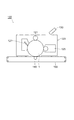
(電子写真感光体)
図1は、本発明の電子写真感光体の好適な一実施形態を示す模式断面図である。図1に示す電子写真感光体1は、導電性支持体2と、導電性支持体2上に設けられた下引層3と、下引層3上に設けられた感光層4とから構成されている。また、感光層4は、下引層3上に形成された電荷発生層5と、電荷発生層5上に形成された電荷輸送層6との積層構造を有している。そして、本実施形態における下引層3は、上述した品質検査方法において電気伝導度の測定値が所定条件を満たす酸化亜鉛粒子を含有している。
(Electrophotographic photoreceptor)
FIG. 1 is a schematic cross-sectional view showing a preferred embodiment of the electrophotographic photosensitive member of the present invention. An
以下、電子写真感光体1の各構成要素について説明する。
Hereinafter, each component of the
先ず、導電性支持体2について説明する。導電性支持体2としては、例えば、アルミニウム、銅、鉄、ステンレス、亜鉛及びニッケルなどの金属ドラム;シート、紙、プラスチック又はガラス上に、アルミニウム、銅、金、銀、白金、パラジウム、チタン、ニッケル−クロム、ステンレス鋼、銅−インジウム等の金属を蒸着するか、酸化インジウム、酸化錫などの導電性金属化合物を蒸着するか、金属箔をラミネートするか、あるいは、カーボンブラック、酸化インジウム、酸化錫−酸化アンチモン粉、金属粉、沃化銅等を結着樹脂に分散したものを塗布することによって、導電処理したドラム状・シート状・プレート状の物など公知の材料を用いることができる。
First, the
導電性支持体として金属パイプ基材を用いる場合、表面は素管のままであっても、予め鏡面切削、エッチング、陽極酸化、粗切削、センタレス研削、サンドブラスト、ウエットホーニングなどの処理が行われていても構わない。 When a metal pipe substrate is used as the conductive support, the surface is still subjected to processing such as mirror cutting, etching, anodizing, rough cutting, centerless grinding, sand blasting, and wet honing, even if the surface is still a bare pipe. It doesn't matter.
次に、下引層3について説明する。下引層3は、上述した品質検査方法において電気伝導度の測定値が所定条件を満たす酸化亜鉛粒子と、結着樹脂とを含んで構成される。この下引層3は、積層構造を有する感光層4の帯電の際に、導電性支持体2から感光層4への電荷の注入を阻止するとともに、感光層4を導電性支持体2に対して一体的に接着保持せしめる接着層としての作用を有するものである。
Next, the
結着樹脂としては、ポリビニルブチラールなどのアセタール樹脂、ポリビニルアルコール樹脂、カゼイン、ポリアミド樹脂、セルロース樹脂、ゼラチン、ポリウレタン樹脂、ポリエステル樹脂、メタクリル樹脂、アクリル樹脂、ポリ塩化ビニル樹脂、ポリビニルアセテート樹脂、塩化ビニル−酢酸ビニル−無水マレイン酸樹脂、シリコーン樹脂、シリコーン−アルキッド樹脂、フェノール樹脂、フェノール−ホルムアルデヒド樹脂、メラミン樹脂などの高分子樹脂化合物が挙げられる。 Binder resins include acetal resins such as polyvinyl butyral, polyvinyl alcohol resin, casein, polyamide resin, cellulose resin, gelatin, polyurethane resin, polyester resin, methacrylic resin, acrylic resin, polyvinyl chloride resin, polyvinyl acetate resin, vinyl chloride. -High molecular resin compounds such as vinyl acetate-maleic anhydride resin, silicone resin, silicone-alkyd resin, phenol resin, phenol-formaldehyde resin, melamine resin.
下引層3に含まれる本発明に係る酸化亜鉛粒子は、上記式(1)を満たす酸化亜鉛粒子が表面処理されたものでもよい。また、酸化亜鉛粒子は、表面処理の異なるもの又は粒子径の異なるもの等の2種以上を混合して用いることもできる。また、酸化亜鉛粒子としては、比表面積が10m2/g以上のものが好ましく、10〜20m2/gであるものがより好ましく、12〜18m2/gであるものが更に好ましい。比表面積値が10m2/g以下のものは帯電性低下を招きやすく、良好な電子写真特性を得にくい傾向がある。
The zinc oxide particles according to the present invention contained in the
酸化亜鉛粒子の表面処理剤としては、所望の特性が得られるものであればよく、公知の材料から選択することができる。例えば、シランカップリング剤、チタネート系カップリング剤、アルミニウム系カップリング剤、界面活性剤等が挙げられる。特に、シランカップリング剤は、良好な電子写真特性が得られるため好ましく用いられる。さらに、アミノ基を有するシランカップリング剤は、下引層に良好なブロッキング性を与えるため好ましく用いられる。 The surface treatment agent for zinc oxide particles is not particularly limited as long as desired characteristics can be obtained, and can be selected from known materials. Examples thereof include silane coupling agents, titanate coupling agents, aluminum coupling agents, and surfactants. In particular, a silane coupling agent is preferably used because good electrophotographic characteristics can be obtained. Furthermore, a silane coupling agent having an amino group is preferably used because it gives a good blocking property to the undercoat layer.
アミノ基を有するシランカップリング剤としては、所望の感光体特性を得られるものであればいかなるものでも用いることができる。具体的には、γ−アミノプロピルトリエトキシシラン、γ−(2−アミノエチル)アミノプロピルトリメトキシシラン、N−β−(アミノエチル)−γ−アミノプロピルトリメトキシシラン、N−β−(アミノエチル)−γ−アミノプロピルメチルメトキシシラン、N,N−ビス(β−ヒドロキシエチル)−γ−アミノプロピルトリエトキシシラン等が挙げられるが、これらに限定されるものではない。 Any silane coupling agent having an amino group can be used as long as it can obtain desired photoreceptor characteristics. Specifically, γ-aminopropyltriethoxysilane, γ- (2-aminoethyl) aminopropyltrimethoxysilane, N-β- (aminoethyl) -γ-aminopropyltrimethoxysilane, N-β- (amino Examples include, but are not limited to, ethyl) -γ-aminopropylmethylmethoxysilane, N, N-bis (β-hydroxyethyl) -γ-aminopropyltriethoxysilane, and the like.
シランカップリング剤は、2種以上混合して使用することもできる。アミノ基を有するシランカップリング剤と併用して用いることができるシランカップリング剤としては、例えば、ビニルトリメトキシシラン、γ−メタクリルオキシプロピル−トリス(β−メトキシエトキシ)シラン、β−(3,4−エポキシシクロヘキシル)エチルトリメトキシシラン、γ−グリシドキシプロピルトリメトキシシラン、ビニルトリアセトキシシラン、γ−メルカプトプロピルトリメトキシシラン、γ−アミノプロピルトリエトキシシラン、N−β−(アミノエチル)−γ−アミノプロピルトリメトキシシラン、N−β−(アミノエチル)−γ−アミノプロピルメチルメトキシシラン、N,N−ビス(β−ヒドロキシエチル)−γ−アミノプロピルトリエトキシシラン、γ−クロルプロピルトリメトキシシラン等が挙げられるが、これらに限定されるものではない。 Two or more silane coupling agents can be used in combination. Examples of the silane coupling agent that can be used in combination with the silane coupling agent having an amino group include vinyltrimethoxysilane, γ-methacryloxypropyl-tris (β-methoxyethoxy) silane, β- (3, 4-epoxycyclohexyl) ethyltrimethoxysilane, γ-glycidoxypropyltrimethoxysilane, vinyltriacetoxysilane, γ-mercaptopropyltrimethoxysilane, γ-aminopropyltriethoxysilane, N-β- (aminoethyl)- γ-aminopropyltrimethoxysilane, N-β- (aminoethyl) -γ-aminopropylmethylmethoxysilane, N, N-bis (β-hydroxyethyl) -γ-aminopropyltriethoxysilane, γ-chloropropyltri Examples include methoxysilane. The present invention is not limited to, et al.
表面処理方法は、公知の方法であればいかなる方法でも使用可能であるが、乾式法又は湿式法を使用することができる。 As the surface treatment method, any known method can be used, but a dry method or a wet method can be used.
乾式法にて表面処理を施す場合には、酸化亜鉛粒子をせん断力の大きなミキサ等で攪拌しながら、直接或いは有機溶媒に溶解させたシランカップリング剤を滴下、乾燥空気や窒素ガスとともに噴霧させることによって、酸化亜鉛粒子を均一に処理することができる。添加又は噴霧する際には溶剤の沸点以下の温度で行うことが好ましい。溶剤の沸点以上の温度で噴霧すると、酸化亜鉛粒子が均一に処理される前に溶剤が蒸発し、シランカップリング剤が局部的にかたまってしまい均一な処理ができにくくなる傾向があり好ましくない。添加又は噴霧した後、さらに100℃以上で焼き付けを行うことが好ましい。焼き付けは所望の電子写真特性が得られる温度、時間であれば任意の範囲で実施できる。 When surface treatment is performed by a dry method, a silane coupling agent dissolved in an organic solvent is dropped and sprayed with dry air or nitrogen gas while stirring zinc oxide particles with a mixer having a large shearing force. Thus, the zinc oxide particles can be uniformly treated. The addition or spraying is preferably performed at a temperature below the boiling point of the solvent. Spraying at a temperature equal to or higher than the boiling point of the solvent is not preferred because the solvent evaporates before the zinc oxide particles are uniformly treated, and the silane coupling agent is locally concentrated, making uniform treatment difficult. After addition or spraying, baking is preferably performed at 100 ° C. or higher. Baking can be carried out in an arbitrary range as long as the temperature and time allow the desired electrophotographic characteristics to be obtained.
湿式法では、酸化亜鉛粒子を溶剤中で攪拌や超音波により、又はサンドミルやアトライター、ボールミル等を用いて分散し、シランカップリング剤溶液を添加し攪拌又は分散したのち、溶剤除去することで均一に処理される。溶剤は、ろ過又は蒸留により留去される。溶剤除去後には、さらに100℃以上で焼き付けを行うことが好ましい。焼き付けは所望の電子写真特性が得られる温度、時間であれば任意の範囲で実施できる。湿式法においては表面処理剤を添加する前に、酸化亜鉛粒子が含有する水分を除去することもできる。その具体例としては、表面処理に用いる溶剤中で酸化亜鉛粒子を攪拌及び加熱しながら除去する方法、溶剤と共沸させて除去する方法が挙げられる。 In the wet method, zinc oxide particles are dispersed in a solvent by stirring or ultrasonic waves, or using a sand mill, attritor, ball mill, etc., and after adding or stirring or dispersing a silane coupling agent solution, the solvent is removed. Uniformly processed. The solvent is distilled off by filtration or distillation. After removing the solvent, baking is preferably performed at 100 ° C. or higher. Baking can be carried out in an arbitrary range as long as the temperature and time allow the desired electrophotographic characteristics to be obtained. In the wet method, moisture contained in the zinc oxide particles can be removed before adding the surface treatment agent. Specific examples thereof include a method of removing zinc oxide particles while stirring and heating in a solvent used for the surface treatment, and a method of removing azeotropically with the solvent.
また、下引層3は、本発明に係る酸化亜鉛粒子以外に、導電性材料を更に含有してもよい。
The
導電性材料としては、例えば、酸化錫、酸化チタン、酸化アルミ等の金属酸化物、及び、有機金属化合物などが挙げられる。有機金属化合物としては、ジルコニウムキレート化合物、ジルコニウムアルコキシド化合物、ジルコニウムカップリング剤等の有機ジルコニウム化合物、チタンキレート化合物、チタンアルコキシド化合物、チタネートカップリング剤等の有機チタン化合物、アルミニウムキレート化合物、アルミニウムカップリング剤等の有機アルミニウム化合物のほか、アンチモンアルコキシド化合物、ゲルマニウムアルコキシド化合物、インジウムアルコキシド化合物、インジウムキレート化合物、マンガンアルコキシド化合物、マンガンキレート化合物、スズアルコキシド化合物、スズキレート化合物、アルミニウムシリコンアルコキシド化合物、アルミニウムチタンアルコキシド化合物、アルミニウムジルコニウムアルコキシド化合物等が挙げられる。 Examples of the conductive material include metal oxides such as tin oxide, titanium oxide, and aluminum oxide, and organometallic compounds. As organometallic compounds, zirconium chelate compounds, zirconium alkoxide compounds, organic zirconium compounds such as zirconium coupling agents, titanium chelate compounds, titanium alkoxide compounds, organotitanium compounds such as titanate coupling agents, aluminum chelate compounds, aluminum coupling agents In addition to organoaluminum compounds such as antimony alkoxide compounds, germanium alkoxide compounds, indium alkoxide compounds, indium chelate compounds, manganese alkoxide compounds, manganese chelate compounds, tin alkoxide compounds, tin chelate compounds, aluminum silicon alkoxide compounds, aluminum titanium alkoxide compounds, And aluminum zirconium alkoxide compounds. .
上記の金属酸化物は表面処理されたものでもよく、その表面処理剤及び表面処理方法としては上述した酸化亜鉛粒子の表面処理剤及び表面処理方法を用いることができる。 The above-mentioned metal oxide may be surface-treated, and as the surface treatment agent and the surface treatment method, the above-described surface treatment agent and surface treatment method for zinc oxide particles can be used.
下引層3は、上記各構成材料を含有する下引層形成用塗布液を用いて構成される。
The
下引層形成用塗布液の混合/分散方法は、ボールミル、ロールミル、サンドミル、アトライター、超音波等を用いる常法が適用される。混合/分散は有機溶剤中で行われるが、有機溶剤としては、結着樹脂を溶解し、また、酸化亜鉛粒子を混合/分散したときにゲル化や凝集を起こさないものであればよい。 As a method for mixing / dispersing the coating solution for forming the undercoat layer, a conventional method using a ball mill, a roll mill, a sand mill, an attritor, an ultrasonic wave, or the like is applied. Mixing / dispersing is performed in an organic solvent, and any organic solvent that dissolves the binder resin and does not cause gelation or aggregation when the zinc oxide particles are mixed / dispersed may be used.
有機溶剤としては、例えば、メタノール、エタノール、n−プロパノール、n−ブタノール、ベンジルアルコール、メチルセルソルブ、エチルセルソルブ、アセトン、メチルエチルケトン、シクロヘキサノン、酢酸メチル、酢酸n−ブチル、ジオキサン、テトラヒドロフラン、メチレンクロライド、クロロホルム、クロルベンゼン、トルエン等の通常の有機溶剤が挙げられる。これらは、1種を単独で又は2種以上を混合して用いることができる。 Examples of the organic solvent include methanol, ethanol, n-propanol, n-butanol, benzyl alcohol, methyl cellosolve, ethyl cellosolve, acetone, methyl ethyl ketone, cyclohexanone, methyl acetate, n-butyl acetate, dioxane, tetrahydrofuran, and methylene chloride. Ordinary organic solvents such as chloroform, chlorobenzene and toluene. These can be used individually by 1 type or in mixture of 2 or more types.
また、下引層3を設けるときに用いる塗布方法としては、ブレードコーティング法、マイヤーバーコーティング法、スプレーコーティング法、浸漬コーティング法、ビードコーティング法、エアーナイフコーティング法、カーテンコーティング法等の通常の方法を用いることができる。
The coating method used when providing the
下引層3の膜厚は、好ましくは1〜30μm、より好ましくは15〜25μmが適当である。また、下引層3は、ビッカース硬度が30以上であることが好ましい。
The thickness of the
また、下引層3はリーク耐性獲得のために適切な抵抗を有していることが好ましく、そのため、下引層3の体積抵抗率は108〜1013Ω・cmであることが好ましく、109〜1012Ω・cmであることが更に好ましい。体積抵抗率が108Ω・cm未満であると、十分なリーク耐性を得ることが困難となる傾向がある。他方、1013Ω・cmを超えると、残留電位上昇を引き起こしてしまう傾向がある。下引層3の体積抵抗率は本発明に係る酸化亜鉛粒子自体の電気抵抗値とその添加量を変化させること、酸化亜鉛粒子の結着樹脂中への分散状態を変化させることで制御することができる。例えば、本実施形態においては、酸化亜鉛粒子が上記水接触工程を経ることにより電気抵抗値が上昇する傾向にある。また、濃度が2.5質量%になるように電気伝導度1.0μS/cm以下の純水と混合したときの混合液の25℃における電気伝導度が10μS/cm以上である酸化亜鉛粒子を用いることにより、分散状態を向上させることができる。
Moreover, it is preferable that the
下引層3に含まれる本発明に係る酸化亜鉛粒子の含有量は、下引層3の固形分全量を基準として35〜40質量%であることが好ましい。また、本実施形態においては、下引層3の体積抵抗率が上記の好適な範囲を満足するように酸化亜鉛粒子を含有させることがより好ましい。
The content of the zinc oxide particles according to the present invention contained in the
電荷発生層5は、上記の下引層3上に電荷発生材料を真空蒸着により形成するか、あるいは、電荷発生材料を有機溶剤及び結着樹脂とともに分散して塗布液を調製し、この塗布液を下引層3上に塗布することにより形成される。
The
電荷発生材料としては、非晶質セレン・結晶性セレン・セレンーテルル合金・セレンーヒ素合金・その他のセレン化合物及びセレン合金、酸化亜鉛・酸化チタン等の無機系光導電体、無金属フタロシアニン、チタニルフタロシアニン、銅フタロシアニン、錫フタロシアニン、ガリウムフタロシアニンなどの各種フタロシアニン顔料、スクエアリウム系、アントアントロン系、ペリレン系、アゾ系、アントラキノン系、ピレン系、ピリリウム塩、チアピリリウム塩等の各種有機顔料及び染料を用いることができる。また、有機顔料は一般に数種の結晶型を有しており、特にフタロシアニン顔料ではα型、β型などをはじめとしてさまざまな結晶型が知られているが、目的にあった感度その他の特性が得られる顔料であるならば、これらのいずれの結晶型でも用いることができる。 Examples of charge generation materials include amorphous selenium, crystalline selenium, selenium-tellurium alloy, selenium-arsenic alloy, other selenium compounds and selenium alloys, inorganic photoconductors such as zinc oxide and titanium oxide, metal-free phthalocyanine, titanyl phthalocyanine, Various phthalocyanine pigments such as copper phthalocyanine, tin phthalocyanine and gallium phthalocyanine, various organic pigments and dyes such as squalium, anthanthrone, perylene, azo, anthraquinone, pyrene, pyrylium salt, thiapyrylium salt, etc. it can. In addition, organic pigments generally have several types of crystals. In particular, phthalocyanine pigments are known for various crystal types including α-type and β-type. Any of these crystal forms can be used as long as the pigment is obtained.
本実施形態において、優れた性能が得られる電荷発生材料として以下の化合物が特に好適である。すなわち、Cukα線を用いたX線回折スペクトルのブラッグ角度(2θ±0.2°)において、少なくとも7.6°,10.0°,25.2°,28.0°の位置に回折ピークを有する結晶型に代表されるヒドロキシガリウムフタロシアニン、Cukα線を用いたX線回折スペクトルのブラッグ角度(2θ±0.2°)において、少なくとも7.3°,16.5°,25.4°,28.1°の位置に回折ピークを有する結晶型に代表されるクロルガリウムフタロシアニン、Cukα線を用いたX線回折スペクトルのブラッグ角度(2θ±0.2°)において、少なくとも9.5°,24.2°,27.3°の位置に回折ピークを有する結晶型に代表されるチタニルフタロシアニンが電荷発生材料として好ましく用いられる。なお、これらの材料は、結晶の形状や測定方法により上記のピーク強度の位置が上記の値から僅かに外れる場合も有るが、X線回折パターンが実質的に一致しているものであれば同じ結晶型であると判断できる。 In the present embodiment, the following compounds are particularly suitable as charge generation materials that can provide excellent performance. That is, at the Bragg angles (2θ ± 0.2 °) of the X-ray diffraction spectrum using Cukα rays, diffraction peaks are present at positions of at least 7.6 °, 10.0 °, 25.2 °, 28.0 °. At least 7.3 °, 16.5 °, 25.4 °, and 28 at a Bragg angle (2θ ± 0.2 °) of an X-ray diffraction spectrum using hydroxygallium phthalocyanine typified by a crystal type having Cukα rays At least 9.5 °, 24. at a Bragg angle (2θ ± 0.2 °) of an X-ray diffraction spectrum using chlorogallium phthalocyanine represented by a crystal type having a diffraction peak at a position of 1 ° and Cukα rays. Titanyl phthalocyanine typified by a crystal form having diffraction peaks at 2 ° and 27.3 ° is preferably used as the charge generation material. These materials may be slightly different from the above values depending on the crystal shape and measurement method, but the same as long as the X-ray diffraction patterns substantially match. It can be judged that it is a crystal form.
電荷発生層5における結着樹脂としては、以下のものを例示することができる。すなわち、ビスフェノールAタイプあるいはビスフェノールZタイプなどのポリカーボネート樹脂およびその共重合体、ポリアリレート樹脂、ポリエステル樹脂、メタクリル樹脂、アクリル樹脂、ポリ塩化ビニル樹脂、ポリスチレン樹脂、ポリビニルアセテート樹脂、スチレン−ブタジエン共重合体樹脂、塩化ビニリデン−アクリルニトリル共重合体樹脂、塩化ビニル−酢酸ビニル−無水マレイン酸樹脂、シリコーン樹脂、シリコーン−アルキド樹脂、フェノール−ホルムアルデヒド樹脂、スチレン−アルキッド樹脂、ポリ−N−ビニルカルバゾールなどが挙げられる。
Examples of the binder resin in the
これらの結着樹脂は、単独あるいは2種以上混合して用いることが可能である。電荷発生材料と結着樹脂との配合比(質量比)は、10:1〜1:10の範囲が望ましい。また、有機溶剤としては、上記の結着樹脂を溶解又は分散可能なものであれば特に制限されないが、例えば、メタノール、エタノール、n−ブタノール、ベンジルアルコール、アセトン、メチルエチルケトン、シクロヘキサノン、酢酸メチル、酢酸n−ブチル、ジオキサン、テトラヒドロフラン、メチレンクロライド、クロロホルム、トルエン、キシレン、クロロベンゼン、ジメチルホルムアミド、ジメチルアセトアミド、水などが挙げられ、これらのうちの1種を単独で用いてもよく、2種以上の混合物として用いもよい。 These binder resins can be used alone or in combination of two or more. The blending ratio (mass ratio) between the charge generating material and the binder resin is preferably in the range of 10: 1 to 1:10. The organic solvent is not particularly limited as long as it can dissolve or disperse the above binder resin. For example, methanol, ethanol, n-butanol, benzyl alcohol, acetone, methyl ethyl ketone, cyclohexanone, methyl acetate, acetic acid Examples include n-butyl, dioxane, tetrahydrofuran, methylene chloride, chloroform, toluene, xylene, chlorobenzene, dimethylformamide, dimethylacetamide, water, and the like. One of these may be used alone, or a mixture of two or more. It may be used as.
また、電荷発生材料と結着樹脂と有機溶剤との分散は、サンドミル、コロイドミル、アトライター、ダイノーミル、ジェットミル、コボールミル、ロールミル、超音波分散機、ゴーリンホモジナイザー、マイクロフルイダイザー、アルティマイザー、マイルダーなどを用いて行うことができる。 Dispersion of charge generation material, binder resin and organic solvent can be performed by sand mill, colloid mill, attritor, dyno mill, jet mill, coball mill, roll mill, ultrasonic disperser, gorin homogenizer, microfluidizer, optimizer, milder. Etc. can be used.
塗布液の塗布方法としては、感光体の形状や用途に応じて浸漬塗布法、リング塗布法、スプレー塗布法、ビード塗布法、ブレード塗布法、ローラ塗布法、ナイフ塗布法、カーテン塗布法などの塗布法を用いて行うことが出来る。乾燥は、室温での指触乾燥の後に加熱乾燥するのが好ましい。加熱乾燥は、30℃〜200℃の温度で5分〜2時間の範囲の時間で行うことが望ましい。 Examples of the application method of the coating liquid include dip coating method, ring coating method, spray coating method, bead coating method, blade coating method, roller coating method, knife coating method, and curtain coating method depending on the shape and application of the photoreceptor. It can be performed using a coating method. Drying is preferably performed by heating after touch drying at room temperature. The heat drying is desirably performed at a temperature in the range of 30 ° C. to 200 ° C. for a time in the range of 5 minutes to 2 hours.
電荷発生層5の厚みは、一般には0.01〜5μm、好ましくは0.05〜2.0μmの範囲に設定される。
The thickness of the
電荷輸送層6は、電荷輸送物質を有機溶剤及び結着樹脂とともに分散して塗布液を調製し、この塗布液を電荷発生層5上に塗布することにより形成される。
The
電荷輸送層6に用いられる電荷輸送物質としては、下記に示すものが例示できる。すなわち、2,5−ビス(p−ジエチルアミノフェニル)−1,3,4−オキサジアゾールなどのオキサジアゾール誘導体、1,3,5−トリフェニル−ピラゾリン、1−[ピリジル−(2)]−3−(p−ジエチルアミノスチリル)−5−(p−ジエチルアミノスチリル)ピラゾリンなどのピラゾリン誘導体、トリフェニルアミン、トリ(P−メチル)フェニルアミン、N,N−ビス(3,4−ジメチルフェニル)ビフェニル−4−アミン、ジベンジルアニリン、9,9−ジメチル−N,N−ジ(p−トリル)フルオレノン−2−アミンなどの芳香族第3級アミノ化合物、N,N’−ジフェニル−N,N’−ビス(3−メチルフェニル)−[1,1−ビフェニル]−4,4’−ジアミンなどの芳香族第3級ジアミノ化合物、3−(4’ジメチルアミノフェニル)−5,6−ジ−(4’−メトキシフェニル)−1,2,4−トリアジンなどの1,2,4−トリアジン誘導体、4−ジエチルアミノベンズアルデヒド−1,1−ジフェニルヒドラゾン、4−ジフェニルアミノベンズアルデヒド−1,1−ジフェニルヒドラゾン、[p−(ジエチルアミノ)フェニル](1−ナフチル)フェニルヒドラゾン、1−ピレンジフェニルヒドラゾン、9−エチル−3−[(2メチル−1−インドリニルイミノ)メチル]カルバゾール、4−(2−メチル−1−インドリニルイミノメチル)トリフェニルアミン、9−メチル−3−カルバゾールジフェニルヒドラゾン、1,1−ジ−(4,4’−メトキシフェニル)アクリルアルデヒドジフェニルヒドラゾン、β,β−ビス(メトキシフェニル)ビニルジフェニルヒドラゾンなどのヒドラゾン誘導体、2−フェニル−4−スチリル−キナゾリンなどのキナゾリン誘導体、6−ヒドロキシ−2,3−ジ(p−メトキシフェニル)−ベンゾフランなどのベンゾフラン誘導体、p−(2,2−ジフェニルビニル)−N,N−ジフェニルアニリンなどのα−スチルベン誘導体、エナミン誘導体、N−エチルカルバゾールなどのカルバゾール誘導体、ポリ−N−ビニルカルバゾールおよびその誘導体などの正孔輸送物質;クロラニル、ブロモアニル、アントラキノン等のキノン系化合物、テトラシアノキノジメタン系化合物、2,4,7−トリニトロフルオレノン、2,4,5,7−テトラニトロ−9−フルオレノン等のフルオレノン化合物、2−(4−ビフェニル)−5−(4−t−ブチルフェニル)−1,3,4−オキサジアゾールや2,5−ビス(4−ナフチル)−1,3,4−オキサジアゾール、2,5−ビス(4−ジエチルアミノフェニル)1,3,4−オキサジアゾールなどのオキサジアゾール系化合物、キサントン系化合物、チオフェン化合物、3,3’,5,5’−テトラ−t−ブチルジフェノキノン、3,5−ジメチル−3’,5’−ジ−t−ブチル−4,4’−ジフェノキノン等のジフェノキノン化合物などの電子輸送物質;あるいは以上に示した化合物からなる基を主鎖又は側鎖に有する重合体などが挙げられる。これらの電荷輸送材料は、1種又は2種以上を組み合せて使用できる。
Examples of the charge transport material used for the
積層型感光体では、電荷輸送材料の電荷輸送極性により感光体の帯電極性が異なる。正孔輸送物質を用いた場合には感光体は負帯電で用いられ、電子輸送物質を用いた場合には正帯電で用いられる。両者を混合した場合には両帯電極性の感光体が可能である。 In the laminated type photoconductor, the charge polarity of the photoconductor varies depending on the charge transport polarity of the charge transport material. When a hole transport material is used, the photoreceptor is used with negative charge, and when an electron transport material is used, it is used with positive charge. When both are mixed, a photoconductor having both charged polarities is possible.
電荷輸送層6に用いられる結着樹脂としては、任意のものを用いることができるが、特に電荷輸送材料と相溶性を有し適当な強度を有するものを用いることが望ましい。このような結着樹脂としては、例えば、ビスフェノールA、ビスフェノールZ、ビスフェノールC、ビスフェノールTPなどからなる各種のポリカーボネート樹脂やその共重合体、ポリアリレート樹脂やその共重合体、ポリエステル樹脂、メタクリル樹脂、アクリル樹脂、ポリ塩化ビニル樹脂、ポリ塩化ビニリデン樹脂、ポリスチレン樹脂、ポリビニルアセテート樹脂、スチレン−ブタジエン共重合体樹脂、塩化ビニル−酢酸ビニル共重合体樹脂、塩化ビニル−酢酸ビニル−無水マレイン酸共重合体樹脂、シリコーン樹脂、シリコーンアルキッド樹脂、フェノール−ホルムアルデヒド樹脂、スチレン−アクリル共重合体樹脂、アチレン−アルキッド樹脂、ポリ−N−ビニルカルバゾール樹脂、ポリビニルブチラール樹脂、ポリフェニレンエーテル樹脂などが挙げられる。これらの樹脂は単独あるいは2種以上の混合物として使用することができる。
As the binder resin used for the
これら結着樹脂として用いられる重合体の分子量は、感光層の膜厚や溶剤などの成膜条件によって適宜選択されるが、通常は粘度平均分子量で3000〜30万、より好ましくは2万〜20万の範囲とされる。 The molecular weight of the polymer used as the binder resin is appropriately selected depending on the film formation conditions such as the film thickness of the photosensitive layer and the solvent, but is usually 3000 to 300,000, more preferably 20,000 to 20 in terms of viscosity average molecular weight. A range of 10,000.
電荷輸送層6は、上記の電荷輸送物質及び結着樹脂を適当な溶媒に溶解させた塗布液を電荷発生層5上に塗布し、乾燥することによって形成することができる。電荷輸送層6の形成に使用される溶媒としては、例えば、ベンゼン、トルエン、クロルベンゼン等の芳香族炭化水素系、アセトン、2−ブタノン等のケトン類、塩化メチレン、クロロホルム、塩化エチレン等のハロゲン化脂肪族炭化水素類、テトラヒドロフラン、ジオキサン、エチレングリコール、ジエチルエーテル等の環状あるいは直鎖状エーテル、あるいはこれらの混合溶剤などを用いることができる。また、塗布液には塗膜の平滑性向上のためのレベリング剤としてシリコーンオイルを微量添加することもできる。電荷輸送材料と結着樹脂との配合比(質量比)は、10:1〜1:5が好ましい。
The
電荷輸送材料と結着樹脂と有機溶剤との分散は、サンドミル、コロイドミル、アトライター、ダイノーミル、ジェットミル、コボールミル、ロールミル、超音波分散機、ゴーリンホモジナイザー、マイクロフルイダイザー、アルティマイザー、マイルダーなどを用いて行うことができる。 Dispersion of charge transport material, binder resin and organic solvent can be done with sand mill, colloid mill, attritor, dyno mill, jet mill, coball mill, roll mill, ultrasonic disperser, gorin homogenizer, microfluidizer, optimizer, milder, etc. Can be used.
塗布液の塗布方法としては、感光体の形状や用途に応じて浸漬塗布法、リング塗布法、スプレー塗布法、ビード塗布法、ブレード塗布法、ローラ塗布法、ナイフ塗布法、カーテン塗布法などの塗布法を用いて行うことが出来る。乾燥は、室温での指触乾燥の後に加熱乾燥するのが好ましい。加熱乾燥は、30℃〜200℃の温度で5分〜2時間の範囲の時間で行うことが望ましい。 Examples of the application method of the coating liquid include dip coating method, ring coating method, spray coating method, bead coating method, blade coating method, roller coating method, knife coating method, and curtain coating method depending on the shape and application of the photoreceptor. It can be performed using a coating method. Drying is preferably performed by heating after touch drying at room temperature. The heat drying is desirably performed at a temperature in the range of 30 ° C. to 200 ° C. for a time in the range of 5 minutes to 2 hours.
電荷輸送層6の膜厚は、一般には5〜50μm、好ましくは10〜40μmの範囲に設定される。
The thickness of the
また、画像形成装置中で発生するオゾンや酸化性ガス、あるいは光や熱による感光体の劣化を防止する目的で、上記の電荷発生層5及び電荷輸送層6により構成される感光層4中には、酸化防止剤、光安定剤、熱安定剤などの添加剤を添加することができる。
Further, for the purpose of preventing deterioration of the photoreceptor due to ozone, oxidizing gas, or light or heat generated in the image forming apparatus, the
酸化防止剤の具体的な化合物例としては、フェノール系酸化防止剤では2,6−ジ−t−ブチル−4−メチルフェノール、スチレン化フェノール、n−オクタデシル−3−(3’,5’−ジ−t−ブチル−4’−ヒドロキシフェニル)−プロピオネート、2,2’−メチレン−ビス−(4−メチル−6−t−ブチルフェノール)、2−t−ブチル−6−(3’−t−ブチル−5’−メチル−2’−ヒドロキシベンジル)−4−メチルフェニルアクリレート、4,4’−ブチリデン−ビス−(3−メチル−6−t−ブチル−フェノール)、4,4’−チオ−ビス−(3−メチル−6−t−ブチルフェノール)、1,3,5−トリス(4−t−ブチル−3−ヒドロキシ−2,6−ジメチルベンジル)イソシアヌレート、テトラキス−[メチレン−3−(3’,5’−ジ−t−ブチル−4’−ヒドロキシ−フェニル)プロピオネート]−メタン、3,9−ビス[2−[3−(3−t−ブチル−4−ヒドロキシ−5−メチルフェニル)プロピオニルオキシ]−1,1−ジメチルエチル]−2,4,8,10−テトラオキサスピロ[5,5]ウンデカン、3−3’,5’−ジ−t−ブチル−4’−ヒドロキシフェニル)プロピオン酸ステアリルなどが挙げられる。ヒンダードアミン系化合物ではビス(2,2,6,6−テトラメチル−4−ピペリジル)セバケート、ビス(1,2,2,6,6−ペンタメチル−4−ピペリジル)セバケート、1−[2−[3−(3,5−ジ−t−ブチル−4−ヒドロキシフェニル)プロピオニルオキシ]エチル]−4−[3−(3,5−ジ−t−ブチル−4−ヒドロキシフェニル)プロピオニルオキシ]−2,2,6,6−テトラメチルピペリジン、8−ベンジル−7,7,9,9−テトラメチル−3−オクチル−1,3,8−トリアザスピロ[4,5]ウンデカン−2,4−ジオン、4−ベンゾイルオキシ−2,2,6,6−テトラメチルピペリジン、コハク酸ジメチル−1−(2−ヒドロキシエチル)−4−ヒドロキシ−2,2,6,6−テトラメチルピペリジン重縮合物、ポリ[{6−(1,1,3,3−テトラメチルブチル)イミノ−1,3,5−トリアジン−2,4−ジイミル}{(2,2,6,6−テトラメチル−4−ピペリジル)イミノ}ヘキサメチレン{(2,3,6,6−テトラメチル−4−ピペリジル)イミノ}]、2−(3,5−ジ−t−ブチル−4−ヒドロキシベンジル)−2−n−ブチルマロン酸ビス(1,2,2,6,6−ペンタメチル−4−ピペリジル)、N,N’−ビス(3−アミノプロピル)エチレンジアミン−2,4−ビス[N−ブチル−N−(1,2,2,6,6,−ペンタメチル−4ピペリジル)アミノ]−6−クロロ−1,3,5−トリアジン縮合物などが挙げられる。有機イオウ系酸化防止剤としてジラウリル−3,3’−チオジプロピオネート、ジミリスチル−3,3’−チオジプロピオネート、ジステアリル−3,3’−チオジプロピオネート、ペンタエリスリトール−テトラキス−(β−ラウリル−チオプロピオネート)、ジトリデシル−3,3’−チオジプロピオネート、2−メルカプトベンズイミダゾールなどが挙げられる。有機燐系酸化防止剤としてトリスノニルフェニルフォスフィート、トリフェニルフォスフィート、トリス(2,4−ジ−t−ブチルフェニル)−フォスフィートなどが挙げられる。また、上記の酸化防止剤の中で有機イオウ系酸化防止剤及び有機燐系酸化防止剤は2次酸化防止剤と呼ばれ、上記フェノール系酸化防止剤又は上記アミン系酸化防止剤などの1次酸化防止剤と併用することにより相乗効果を得ることができる。 Specific examples of the antioxidant include 2,6-di-tert-butyl-4-methylphenol, styrenated phenol, n-octadecyl-3- (3 ′, 5′-) for phenolic antioxidants. Di-t-butyl-4'-hydroxyphenyl) -propionate, 2,2'-methylene-bis- (4-methyl-6-t-butylphenol), 2-t-butyl-6- (3'-t- Butyl-5'-methyl-2'-hydroxybenzyl) -4-methylphenyl acrylate, 4,4'-butylidene-bis- (3-methyl-6-tert-butyl-phenol), 4,4'-thio- Bis- (3-methyl-6-tert-butylphenol), 1,3,5-tris (4-tert-butyl-3-hydroxy-2,6-dimethylbenzyl) isocyanurate, tetrakis- [methylene- -(3 ', 5'-di-t-butyl-4'-hydroxy-phenyl) propionate] -methane, 3,9-bis [2- [3- (3-t-butyl-4-hydroxy-5- Methylphenyl) propionyloxy] -1,1-dimethylethyl] -2,4,8,10-tetraoxaspiro [5,5] undecane, 3-3 ′, 5′-di-t-butyl-4′- And hydroxyphenyl) stearyl propionate. Among hindered amine compounds, bis (2,2,6,6-tetramethyl-4-piperidyl) sebacate, bis (1,2,2,6,6-pentamethyl-4-piperidyl) sebacate, 1- [2- [3 -(3,5-di-tert-butyl-4-hydroxyphenyl) propionyloxy] ethyl] -4- [3- (3,5-di-tert-butyl-4-hydroxyphenyl) propionyloxy] -2, 2,6,6-tetramethylpiperidine, 8-benzyl-7,7,9,9-tetramethyl-3-octyl-1,3,8-triazaspiro [4,5] undecane-2,4-dione, 4, -Benzoyloxy-2,2,6,6-tetramethylpiperidine, dimethyl-1- (2-hydroxyethyl) -4-hydroxy-2,2,6,6-tetramethylpiperidine heavy succinate Compound, poly [{6- (1,1,3,3-tetramethylbutyl) imino-1,3,5-triazine-2,4-diimyl} {(2,2,6,6-tetramethyl- 4-piperidyl) imino} hexamethylene {(2,3,6,6-tetramethyl-4-piperidyl) imino}], 2- (3,5-di-t-butyl-4-hydroxybenzyl) -2- n-Butylmalonate bis (1,2,2,6,6-pentamethyl-4-piperidyl), N, N′-bis (3-aminopropyl) ethylenediamine-2,4-bis [N-butyl-N— (1,2,2,6,6, -pentamethyl-4piperidyl) amino] -6-chloro-1,3,5-triazine condensate and the like. Dilauryl-3,3′-thiodipropionate, dimyristyl-3,3′-thiodipropionate, distearyl-3,3′-thiodipropionate, pentaerythritol-tetrakis- ( β-lauryl-thiopropionate), ditridecyl-3,3′-thiodipropionate, 2-mercaptobenzimidazole and the like. Examples of the organophosphorus antioxidant include trisnonylphenyl phosfte, triphenyl phosfte, tris (2,4-di-t-butylphenyl) -phosfte, and the like. Among the above antioxidants, organic sulfur-based antioxidants and organic phosphorus-based antioxidants are called secondary antioxidants, and primary antioxidants such as the above-mentioned phenolic antioxidants or amine-based antioxidants. A synergistic effect can be acquired by using together with antioxidant.
光安定剤としては、例えば、ベンゾフェノン系、ベンゾトリアゾール系、ジチオカルバメート系、テトラメチルピペリジン系などの誘導体が挙げられる。 Examples of the light stabilizer include derivatives such as benzophenone, benzotriazole, dithiocarbamate, and tetramethylpiperidine.
ベンゾフェノン系光安定剤としては2−ヒドロキシ−4−メトキシベンゾフェノン、2−ヒドロキシ−4−オクトキシベンゾフェノン、2,2’−ジ−ヒドロキシ−4−メトキシベンゾフェノンなどが挙げられる。ベンゾトリアゾール系光安定剤として2−(−2’−ヒドロキシ−5’−メチルフェニル−)−ベンゾトリアゾール、2−[2’−ヒドロキシ−3’−(3’’,4’’,5’’,6’’−テトラ−ヒドロフタルイミド−メチル)−5’−メチルフェニル]−ベンゾトリアゾール、2−(−2’−ヒドロキシ−3’−t−ブチル−5’−メチルフェニル−)−5−クロロベンゾトリアゾール、2−(2’−ヒドロキシ−3’−t−ブチル−5’−メチルフェニル−)−5−クロロベンゾトリアゾール、2−(2’−ヒドロキシ−3’,5’−t−ブチルフェニル−)−ベンゾトリアゾール、2−(2’−ヒドロキシ−5’−t−オクチルフェニル)−ベンゾトリアゾール、2−(2’−ヒドロキシ−3’,5’−ジ−t−アミルフェニル−)−ベンゾトリアゾールなどが挙げられる。その他、2,4,ジ−t−ブチルフェニル−3’,5’−ジ−t−ブチル−4’−ヒドロキシベンゾエート、ニッケルジブチル−ジチオカルバメートなどを用いることもできる。 Examples of the benzophenone light stabilizer include 2-hydroxy-4-methoxybenzophenone, 2-hydroxy-4-octoxybenzophenone, and 2,2'-di-hydroxy-4-methoxybenzophenone. 2-(-2′-hydroxy-5′-methylphenyl-)-benzotriazole, 2- [2′-hydroxy-3 ′-(3 ″, 4 ″, 5 ″) as benzotriazole light stabilizers , 6 ″ -tetra-hydrophthalimido-methyl) -5′-methylphenyl] -benzotriazole, 2-(-2′-hydroxy-3′-tert-butyl-5′-methylphenyl-)-5-chloro Benzotriazole, 2- (2′-hydroxy-3′-t-butyl-5′-methylphenyl-)-5-chlorobenzotriazole, 2- (2′-hydroxy-3 ′, 5′-t-butylphenyl) -)-Benzotriazole, 2- (2'-hydroxy-5'-t-octylphenyl) -benzotriazole, 2- (2'-hydroxy-3 ', 5'-di-t-amylphenyl-)- Examples include benzotriazole. In addition, 2,4, di-t-butylphenyl-3 ', 5'-di-t-butyl-4'-hydroxybenzoate, nickel dibutyl-dithiocarbamate, and the like can be used.
また、感度の向上、残留電位の低減、繰り返し使用時の疲労低減等を目的として、感光層4中に少なくとも1種の電子受容性物質を含有させることができる。かかる電子受容性物質としては、無水コハク酸、無水マレイン酸、ジブロム無水マレイン酸、無水フタル酸、テトラブロム無水フタル酸、テトラシアノエチレン、テトラシアノキノジメタン、o−ジニトロベンゼン、m−ジニトロベンゼン、クロラニル、ジニトロアントラキノン、トリニトロフルオレノン、ピクリン酸、o−ニトロ安息香酸、p−ニトロ安息香酸、フタル酸等が挙げられる。これらのうち、フルオレノン系又はキノン系化合物や、−Cl、−CN、−NO2等の電子吸引性置換基を有するベンゼン誘導体が特に好ましい。
Further, at least one kind of electron accepting substance can be contained in the
さらに、感光層の上に、必要に応じて保護層を形成することが可能である。 Furthermore, a protective layer can be formed on the photosensitive layer as necessary.
保護層としては、例えば、絶縁性樹脂中に半導電性微粒子や電荷輸送性物質を分散させた層が挙げられる。半導電性微粒子としては、電気抵抗が109Ω・cm以下で白色、灰色もしくは青白色を呈する平均粒径が0.3μm以下好ましくは0.1μm以下の微粒子が適当である。絶縁性樹脂としては、ポリアミド、ポリウレタン、ポリエステル、エポキシ樹脂、ポリケトン、ポリカーボネート等の縮合樹脂や、ポリビニルケトン、ポリスチレン、ポリアクリルアミド、ポリビニルブチラールのようなビニル重合体等が上げられる。 Examples of the protective layer include a layer in which semiconductive fine particles and a charge transporting substance are dispersed in an insulating resin. As the semiconductive fine particles, fine particles having an electric resistance of 10 9 Ω · cm or less and a white, gray or bluish average particle size of 0.3 μm or less, preferably 0.1 μm or less are suitable. Examples of the insulating resin include condensation resins such as polyamide, polyurethane, polyester, epoxy resin, polyketone, and polycarbonate, and vinyl polymers such as polyvinyl ketone, polystyrene, polyacrylamide, and polyvinyl butyral.
また、反応性官能基を有する電荷輸送性物質を熱可塑性樹脂或いは熱硬化性樹脂と反応させて保護層を形成することができる。 Further, a protective layer can be formed by reacting a charge transporting substance having a reactive functional group with a thermoplastic resin or a thermosetting resin.
次に、本発明の画像形成装置の好ましい例について図2を参照しながら説明する。 Next, a preferred example of the image forming apparatus of the present invention will be described with reference to FIG.
(画像形成装置)
図2は、本発明の画像形成装置の好適な一実施形態を示す模式図である。図2に示す画像形成装置100は、画像形成装置本体(図示せず)に、上記本発明の電子写真感光体1を備えるプロセスカートリッジ120と、露光装置130と、転写装置140と、中間転写体150とを備える。なお、画像形成装置100において、露光装置130はプロセスカートリッジ120の開口部から電子写真感光体1に露光可能な位置に配置されており、転写装置140は中間転写体150を介して電子写真感光体1に対向する位置に配置されており、中間転写体150はその一部が電子写真感光体1に当接可能に配置されている。
(Image forming device)
FIG. 2 is a schematic diagram showing a preferred embodiment of the image forming apparatus of the present invention. An
プロセスカートリッジ120は、ケース内に電子写真感光体1とともに帯電装置121、現像装置125、クリーニング装置127を、取り付けレールにより組み合わせて一体化したものである。なお、ケースには、露光のための開口部が設けられている。
The
帯電装置121は、電子写感光体1を接触方式により帯電させるものであり、例えば、ブラシ帯電器、ロール形状の接触帯電装置などを使用できる。また、本実施形態においては、接触帯電装置の代わりに、コロトロン、スコロトロン、イオン放電器などの非接触型の帯電装置を用いることもできる。
The charging
露光装置130は、レーザビーム光源、LED、ポリシリコンTFT駆動蛍光表示素子アレイ、液晶シャッタ露光装置など各種のものを使用することができる。光源の波長は感光体の感度域に合ったものを使用することができる。レーザビーム光源を用いる場合には一般的には赤から近赤外領域に当たる600〜850nmの波長の赤外レーザが使用されるが、ビーム光を小さくする或いは感光体の感度とのマッチングを高める目的で、青色光(350〜500nm)など低波長側の光源を使用することも可能である。
As the
また、レーザ光源でマルチビーム方式の光源を用いて、1本のレーザ光源でそれぞれの色部分に光を導いて露光する方式も利用することが可能である。LEDアレイを用いる場合にはレーザスキャナー方式のプリンタと比較するとポリゴンミラーのような回転する部品が無いため高速化及び小型化に有利である。 Further, it is also possible to use a method in which a multi-beam type light source is used as a laser light source and light is guided to each color portion with a single laser light source for exposure. When an LED array is used, compared with a laser scanner printer, there is no rotating part such as a polygon mirror, which is advantageous for speeding up and downsizing.
現像装置125は、電子写真感光体1上の静電潜像を現像してトナー像を形成するものである。現像剤としては、公知の1成分、2成分、或いはこの中間にあたる構成の現像剤を用いることができる。また、トナーには混連・粉砕方式のトナーや重合方式のトナーのいずれも使用することができる。トナーの粒径はシステム設定に応じて適宜設定される。トナーの粒径は固体トナーの場合には3〜20μmの範囲に設定することが好ましい。また、より好適な画質を得られるように球形トナーを使用することも可能である。
The developing
現像装置125の現像スリーブは公知のものが使用できる。材質としては、アルミニウム、ステンレス等が使用可能である。現像剤を現像領域に長期にわたって安定して搬送するためには、現像スリーブ表面に溶射処理、サンドブラスト処理、溝付け処理などの表面粗面化処理をすることが有効である。複数のカラートナーを重ね合わすカラー画像を形成する場合には、トナーの混合が少ない非接触現像方式を用いることが有効である。
A known developing sleeve of the developing
転写装置140は、電子写真感光体1上のトナー像を被転写媒体(中間転写体150)に転写するものであればよく、例えば、ロール形状の通常使用されるものが使用される。
The
中間転写体150としては、半導電性を付与したポリイミド、ポリアミドイミド、ポリカーボネート、ポリアリレート、ポリエステル、ゴム等のベルト状のもの(中間転写ベルト)が使用される。また、中間転写体150の形態としては、ベルト状以外にドラム状のものを用いることもできる。
As the
クリーニング装置127は、ブレードクリーニング、ブラシクリーニング、磁気ブラシクリーニング、エアークリーニングなど公知のものが使用される。また、クリーニング効率の向上と感光体の電位安定化のために、除電露光装置が併設されていてもよい。
As the
上述のように、画像形成装置100は、本発明の電子写真感光体1を備えている。これにより、長期に亘って画質欠陥のない画像を形成することが可能となっている。
As described above, the
また、図3は、本発明の画像形成装置の他の実施形態を示す模式図である。画像形成装置200は、プロセスカートリッジ120を4つ搭載したタンデム方式のフルカラー画像形成装置である。画像形成装置200では、中間転写体150上に4つのプロセスカートリッジ120がそれぞれ並列に配置されており、1色に付き1つの電子写真感光体が使用できる構成となっている。なお、画像形成装置200は、タンデム方式であること以外は、画像形成装置100と同様の構成を有している。
FIG. 3 is a schematic view showing another embodiment of the image forming apparatus of the present invention. The
図4は、本発明の画像形成装置の他の実施形態を示す模式図である。図4に示した画像形成装置300は、1つの電子写真感光体で複数の色のトナー画像を形成させる、所謂4サイクル方式の画像形成装置である。画像形成装置300は、駆動装置(図示せず)により所定の回転速度で図中の矢印Cの方向に回転される感光体ドラム301を備えており、この感光体ドラム301は、上述した本実施形態の電子写真感光体1から構成されている。また、感光体ドラム301の上方には、感光体ドラム301の外周面を帯電させる帯電装置322が設けられている。
FIG. 4 is a schematic view showing another embodiment of the image forming apparatus of the present invention. The
また、帯電装置322の上方には面発光レーザアレイを露光光源として備える露光装置330が配置されている。露光装置330は、光源から射出される複数本のレーザビームを、形成すべき画像に応じて変調すると共に、主走査方向に偏向し、感光体ドラム301の外周面上を感光体ドラム301の軸線と平行に走査させる。これにより、帯電した感光体ドラム301の外周面上に静電潜像が形成される。
An
感光体ドラム301の側方には現像装置325が配置されている。現像装置325は回転可能に配置されたローラ状の収容体を備えている。この収容体の内部には4個の収容部が形成されており、各収容部には現像器325Y,325M,325C,325Kが設けられている。現像器325Y,325M,325C,325Kは各々現像ローラ326を備え、内部に各々Y,M,C,Kの色のトナーを貯留している。
A developing
画像形成装置300でのフルカラーの画像の形成は、感光体ドラム301が4回転する間に行われる。すなわち、感光体ドラム301が4回転する間、帯電装置322は感光体ドラム301の外周面の帯電、露光装置330は、形成すべきカラー画像を表すY,M,C,Kの画像データのうちの何れかに応じて変調したレーザビームを感光体ドラム301の外周面上で走査させることを、感光体ドラム301が1回転する毎にレーザビームの変調に用いる画像データを切替えながら繰り返す。また現像装置325は、現像器325Y,325M,325C,325Kの何れかの現像ローラ326が感光体ドラム301の外周面に対応している状態で、外周面に対応している現像器を作動させ、感光体ドラム301の外周面に形成された静電潜像を特定の色に現像し、感光体ドラム301の外周面上に特定色のトナー像を形成させることを、感光体ドラム301が1回転する毎に、静電潜像の現像に用いる現像器が切り替わるように収容体を回転させながら繰り返す。これにより、感光体ドラム301が1回転する毎に、感光体ドラム301の外周面上には、Y,M,C,Kのトナー像が互いに重なるように順次形成されることになり、感光体ドラム301が4回転した時点で感光体ドラム301の外周面上にフルカラーのトナー像が形成されることになる。
The full-color image is formed by the
また、感光体ドラム301の略下方には無端の中間転写ベルト350が配設されている。中間転写ベルト350はローラ351,353,355に巻掛けられており、外周面が感光体ドラム301の外周面に接触するように配置されている。ローラ351,353,355は図示しないモータの駆動力が伝達されて回転し、中間転写ベルト350を図4矢印D方向に回転させる。
Further, an endless
中間転写ベルト350を挟んで感光体ドラム301の反対側には転写装置(転写器)340が配置されており、感光体ドラム301の外周面上に形成されたトナー像は転写装置340によって中間転写ベルト350の画像形成面に転写される。
A transfer device (transfer device) 340 is disposed on the opposite side of the
また、感光体ドラム301を挟んで現像装置325の反対側には、感光体ドラム301の外周面に潤滑剤供給装置329及びクリーニング装置327が配置されている。感光体ドラム301の外周面上に形成されたトナー像が中間転写ベルト350に転写されると、潤滑剤供給装置329により感光体ドラム301の外周面に潤滑剤が供給され、当該外周面のうち転写されたトナー像を担持していた領域がクリーニング装置327により清浄化される。
A
中間転写ベルト350よりも下方側にはトレイ360が配置されており、トレイ360内には記録材料としての用紙Pが多数枚積層された状態で収容されている。トレイ360の左斜め上方には取り出しローラ361が配置されており、取り出しローラ361による用紙Pの取り出し方向下流側にはローラ対363、ローラ365が順に配置されている。積層状態で最も上方に位置している記録紙は、取り出しローラ361が回転されることによりトレイ360から取り出され、ローラ対363、ローラ365によって搬送される。
A
また、中間転写ベルト350を挟んでローラ355の反対側には転写装置342が配置されている。ローラ対363、ローラ365によって搬送された用紙Pは、中間転写ベルト350と転写器342の間に送り込まれ、中間転写ベルト350の画像形成面に形成されたトナー像が転写装置342によって転写される。転写装置342よりも用紙Pの搬送方向下流側には、定着ローラ対を備えた定着装置344が配置されており、トナー像が転写された用紙Pは、転写されたトナー像が定着装置344によって溶融定着された後に画像形成装置300の機体外へ排出され、排紙トレイ(図示せず)上に載置される。
Further, a
以下、実施例により本発明を更に詳細に説明するが、本発明はこれらの実施例に限定されるものではない。 EXAMPLES Hereinafter, although an Example demonstrates this invention further in detail, this invention is not limited to these Examples.
<酸化亜鉛粒子の製造>
(製造例1)
塩化亜鉛10質量部を水道水50質量部に溶解した溶液に、炭酸ナトリウム8質量部を水道水40質量部に溶解した溶液を徐々に添加して塩基性炭酸亜鉛を沈殿させた。次に、塩基性炭酸亜鉛が沈殿する液をメンブレンフィルタで濾過し、続いてフィルタ上の塩基性炭酸亜鉛を純水(電気伝導度(25℃):0.8μmS/cm、温度:20℃)1000質量部で20分間洗浄した。洗浄後の塩基性炭酸亜鉛を550℃で4時間培焼し、酸化亜鉛粒子(体積平均粒径:2.3μm、比表面積:15m2/g)を得た。この酸化亜鉛粒子を「酸化亜鉛粒子−1A」とした。なお、上記で使用した水道水は、25℃における電気伝導度が202μS/cmであった。
<Manufacture of zinc oxide particles>
(Production Example 1)
To a solution in which 10 parts by mass of zinc chloride was dissolved in 50 parts by mass of tap water, a solution in which 8 parts by mass of sodium carbonate was dissolved in 40 parts by mass of tap water was gradually added to precipitate basic zinc carbonate. Next, the liquid in which basic zinc carbonate is precipitated is filtered through a membrane filter, and then the basic zinc carbonate on the filter is purified with pure water (electric conductivity (25 ° C.): 0.8 μm S / cm, temperature: 20 ° C.). Washing was performed at 1000 parts by mass for 20 minutes. The basic zinc carbonate after washing was cultured at 550 ° C. for 4 hours to obtain zinc oxide particles (volume average particle size: 2.3 μm, specific surface area: 15 m 2 / g). This zinc oxide particle was designated as “zinc oxide particle-1A”. The tap water used above had an electric conductivity of 202 μS / cm at 25 ° C.
次に、上記で得られた「酸化亜鉛粒子−1A」100質量部と、トルエン450質量部及びメタノール50質量部の混合溶媒とを撹拌混合し、これにシランカップリング剤であるγ−(2−アミノエチル)アミノプロピルトリメトキシシラン(商品名「KBM603」、信越化学社製)1.5質量部を添加し、更に2時間撹拌した。続いて、減圧蒸留により溶媒を除去した後、120℃で2時間加熱し、表面処理された酸化亜鉛粒子を得た。この酸化亜鉛粒子を「酸化亜鉛粒子−1B」とした。 Next, 100 parts by mass of the “zinc oxide particles-1A” obtained above and a mixed solvent of 450 parts by mass of toluene and 50 parts by mass of methanol are mixed with stirring, and γ- (2 -Aminoethyl) 1.5 parts by mass of aminopropyltrimethoxysilane (trade name “KBM603”, manufactured by Shin-Etsu Chemical Co., Ltd.) was added, and the mixture was further stirred for 2 hours. Subsequently, after removing the solvent by distillation under reduced pressure, it was heated at 120 ° C. for 2 hours to obtain surface-treated zinc oxide particles. This zinc oxide particle was designated as “zinc oxide particle-1B”.
(製造例2)
塩化亜鉛10質量部を水道水50質量部に溶解した溶液に、炭酸ナトリウム8質量部を水道水40質量部に溶解した溶液を徐々に添加して塩基性炭酸亜鉛を沈殿させた。次に、塩基性炭酸亜鉛が沈殿する液をメンブレンフィルタで濾過し、続いてフィルタ上の塩基性炭酸亜鉛を水道水500質量部で10分間洗浄した。洗浄後の塩基性炭酸亜鉛を550℃で4時間培焼し、酸化亜鉛粒子(体積平均粒径:2.1μm、比表面積:16m2/g)を得た。なお、上記で使用した水道水は、25℃における電気伝導度が202μS/cmであった。
(Production Example 2)
To a solution in which 10 parts by mass of zinc chloride was dissolved in 50 parts by mass of tap water, a solution in which 8 parts by mass of sodium carbonate was dissolved in 40 parts by mass of tap water was gradually added to precipitate basic zinc carbonate. Next, the liquid in which basic zinc carbonate was precipitated was filtered with a membrane filter, and then the basic zinc carbonate on the filter was washed with 500 parts by mass of tap water for 10 minutes. The basic zinc carbonate after washing was cultured at 550 ° C. for 4 hours to obtain zinc oxide particles (volume average particle size: 2.1 μm, specific surface area: 16 m 2 / g). The tap water used above had an electric conductivity of 202 μS / cm at 25 ° C.
次に、上記で得られた酸化亜鉛粒子1質量部をメンブレンフィルタ上に載せ、水道水50質量部で10分間濾過洗浄した。続いて、洗浄後の酸化亜鉛粒子を100℃で2時間減圧乾燥(圧力:10mmHg(1333.22Pa))した。この乾燥後の酸化亜鉛粒子を「酸化亜鉛粒子−2A」とした。なお、洗浄に使用した水道水は、25℃における電気伝導度が202μS/cmであった。 Next, 1 part by mass of the zinc oxide particles obtained above was placed on a membrane filter, and washed by filtration with 50 parts by mass of tap water for 10 minutes. Subsequently, the washed zinc oxide particles were dried under reduced pressure at 100 ° C. for 2 hours (pressure: 10 mmHg (1333.22 Pa)). The dried zinc oxide particles were designated as “zinc oxide particles-2A”. The tap water used for washing had an electric conductivity of 202 μS / cm at 25 ° C.
次に、上記で得られた「酸化亜鉛粒子−2A」100質量部と、トルエン450質量部及びメタノール50質量部の混合溶媒とを撹拌混合し、これにシランカップリング剤であるγ−(2−アミノエチル)アミノプロピルトリメトキシシラン(商品名「KBM603」、信越化学社製)1.5質量部を添加し、更に2時間撹拌した。続いて、減圧蒸留により溶媒を除去した後、120℃で2時間加熱し、表面処理された酸化亜鉛粒子を得た。この酸化亜鉛粒子を「酸化亜鉛粒子−2B」とした。 Next, 100 parts by mass of the “zinc oxide particles-2A” obtained above and a mixed solvent of 450 parts by mass of toluene and 50 parts by mass of methanol are mixed with stirring, and γ- (2 -Aminoethyl) 1.5 parts by mass of aminopropyltrimethoxysilane (trade name “KBM603”, manufactured by Shin-Etsu Chemical Co., Ltd.) was added, and the mixture was further stirred for 2 hours. Subsequently, after removing the solvent by distillation under reduced pressure, it was heated at 120 ° C. for 2 hours to obtain surface-treated zinc oxide particles. This zinc oxide particle was designated as “zinc oxide particle-2B”.
(製造例3)
先ず、製造例1において、塩基性炭酸亜鉛を純水で洗浄する代わりに、水道水500質量部で10分間洗浄したこと以外は製造例1と同様にして、表面処理する前の酸化亜鉛粒子を得た。この酸化亜鉛粒子を「酸化亜鉛粒子−3A」とした。なお、上記で使用した水道水は、25℃における電気伝導度が202μS/cmであった。
(Production Example 3)
First, in Production Example 1, instead of washing the basic zinc carbonate with pure water, the zinc oxide particles before surface treatment were treated in the same manner as in Production Example 1 except that the washing was performed with 500 parts by mass of tap water for 10 minutes. Obtained. This zinc oxide particle was designated as “zinc oxide particle-3A”. The tap water used above had an electric conductivity of 202 μS / cm at 25 ° C.
次に、製造例1における「酸化亜鉛粒子−1A」の代わりに上記で得られた「酸化亜鉛粒子−3A」を用いたこと以外は製造例1と同様にして、表面処理された酸化亜鉛粒子を得た。この酸化亜鉛粒子を「酸化亜鉛粒子−3B」とした。 Next, surface-treated zinc oxide particles were prepared in the same manner as in Production Example 1 except that “Zinc oxide particles-3A” obtained above was used instead of “Zinc oxide particles-1A” in Production Example 1. Got. This zinc oxide particle was designated as “zinc oxide particle-3B”.
(製造例4)
先ず、製造例1において、塩基性炭酸亜鉛を純水で洗浄する代わりに、水道水500質量部で20分間洗浄したこと以外は製造例1と同様にして、表面処理する前の酸化亜鉛粒子を得た。この酸化亜鉛粒子を「酸化亜鉛粒子−4A」とした。なお、上記で使用した水道水は、25℃における電気伝導度が202μS/cmであった。
(Production Example 4)
First, in Production Example 1, instead of washing the basic zinc carbonate with pure water, the zinc oxide particles before surface treatment were treated in the same manner as in Production Example 1 except that the washing was performed with 500 parts by mass of tap water for 20 minutes. Obtained. This zinc oxide particle was designated as “zinc oxide particle-4A”. The tap water used above had an electric conductivity of 202 μS / cm at 25 ° C.
次に、製造例1における「酸化亜鉛粒子−1A」の代わりに上記で得られた「酸化亜鉛粒子−4A」を用いたこと以外は製造例1と同様にして、表面処理された酸化亜鉛粒子を得た。この酸化亜鉛粒子を「酸化亜鉛粒子−4B」とした。 Next, surface-treated zinc oxide particles were prepared in the same manner as in Production Example 1 except that “Zinc oxide particles-4A” obtained above was used instead of “Zinc oxide particles-1A” in Production Example 1. Got. This zinc oxide particle was designated as “zinc oxide particle-4B”.
<電気伝導度の測定>
上記で得られた酸化亜鉛粒子−1A、酸化亜鉛粒子−2A、酸化亜鉛粒子−3A及び酸化亜鉛粒子−4Aをそれぞれ分散させた純水の電気伝導度を以下の手順に従って求めた。得られた結果を表1に示す。
(1) 電気伝導度が1.0μS/cm以下の純水に、酸化亜鉛粒子を濃度が2.5質量%となるように添加する。
(2) 超音波発生機(「UA150」、国際電気エルテック株式会社製)を用いて、純水中の酸化亜鉛粒子を10分間超音波分散させる。
(3) 電気伝導度計(「CEH−12」、堀場製作所製)を用いて、酸化亜鉛粒子を分散させた混合液(分散液)の電気伝導度(温度25℃)を測定する。
<Measurement of electrical conductivity>
The electric conductivity of pure water in which the zinc oxide particles-1A, zinc oxide particles-2A, zinc oxide particles-3A and zinc oxide particles-4A obtained above were dispersed was determined according to the following procedure. The obtained results are shown in Table 1.
(1) Zinc oxide particles are added to pure water having an electric conductivity of 1.0 μS / cm or less so that the concentration is 2.5 mass%.
(2) Using an ultrasonic generator (“UA150”, manufactured by Kokusai Electric Ltec Co., Ltd.), zinc oxide particles in pure water are ultrasonically dispersed for 10 minutes.
(3) Using an electric conductivity meter (“CEH-12”, manufactured by HORIBA, Ltd.), the electric conductivity (temperature: 25 ° C.) of the mixed liquid (dispersed liquid) in which the zinc oxide particles are dispersed is measured.

<電子写真感光体の作製>
(実施例1)
先ず、円筒状のアルミニウム基材(直径30mm、長さ349mm、肉厚1mm)を用意した。
<Production of electrophotographic photoreceptor>
Example 1
First, a cylindrical aluminum substrate (diameter 30 mm, length 349 mm,
次に、製造例1で得られた表面処理された「酸化亜鉛粒子−1B」を60質量部、硬化剤としてブロック化イソシアネート(「スミジュールBL3175」、住友バイエルンウレタン社製)を15質量部、触媒としてジオクチルスズジラウレート(キシダ化学社製)を0.015質量部、ブチラール樹脂(「BM−1」、積水化学社製)5質量部をメチルエチルケトン45質量部に溶解した溶液、及び、メチルエチルケトンを10質量部混合し、1mmφのガラスビーズを用いてダイノミルにて2時間の分散を行い分散液を得た。次に、得られた分散液100質量部に、干渉防止粉としてシリコーン樹脂粒子(「トスパール145」、東芝GEシリコーン社製)6質量部をメチルエチルケトン4質量部に分散させた分散液4質量部を添加し、下引層形成用塗布液を得た。この塗布液を、浸漬塗布法にてアルミニウム基材上に塗布し、160℃で40分の乾燥硬化を行い、膜厚23.5μmの下引層を形成した。 Next, 60 parts by mass of the surface-treated “zinc oxide particles-1B” obtained in Production Example 1 and 15 parts by mass of blocked isocyanate (“Sumijoule BL3175”, manufactured by Sumitomo Bayern Urethane Co., Ltd.) as a curing agent, As a catalyst, 0.015 parts by mass of dioctyltin dilaurate (manufactured by Kishida Chemical Co., Ltd.), 5 parts by mass of butyral resin (“BM-1”, manufactured by Sekisui Chemical Co., Ltd.) dissolved in 45 parts by mass of methyl ethyl ketone, and 10 methyl ethyl ketone Mass parts were mixed, and dispersion was obtained by dispersing for 2 hours with a dynomill using 1 mmφ glass beads. Next, 4 parts by mass of dispersion obtained by dispersing 6 parts by mass of silicone resin particles (“Tospearl 145”, manufactured by Toshiba GE Silicone) as interference prevention powder in 4 parts by mass of methyl ethyl ketone in 100 parts by mass of the obtained dispersion. This was added to obtain a coating solution for forming the undercoat layer. This coating solution was applied onto an aluminum substrate by a dip coating method, followed by drying and curing at 160 ° C. for 40 minutes to form an undercoat layer having a thickness of 23.5 μm.
次に、X線回折スペクトルにおけるブラッグ角(2θ±0.2°)が少なくとも7.4°、16.6°、25.5°、28.3°の位置に回折ピークを持つ塩化ガリウムフタロシアニン15質量部を、塩化ビニル−酢酸ビニル共重合樹脂(「VMCH」、日本ユニカー社製)10質量部及びn−酢酸ブチル300質量部と混合し、これを外径1mmのガラスビーズと共にサンドミルで4時間分散処理することにより電荷発生層形成用塗布液を調製した。得られた塗布液を下引層が設けられた導電性支持体上に浸漬塗布し、常温で乾燥して膜厚0.2μmの電荷発生層を形成した。 Next, gallium chloride phthalocyanine 15 having diffraction peaks at positions where the Bragg angle (2θ ± 0.2 °) in the X-ray diffraction spectrum is at least 7.4 °, 16.6 °, 25.5 °, and 28.3 °. Part by mass is mixed with 10 parts by mass of vinyl chloride-vinyl acetate copolymer resin (“VMCH”, manufactured by Nippon Unicar Co., Ltd.) and 300 parts by mass of n-butyl acetate, and this is mixed with glass beads having an outer diameter of 1 mm in a sand mill for 4 hours. A coating solution for forming a charge generation layer was prepared by a dispersion treatment. The obtained coating solution was dip-coated on a conductive support provided with an undercoat layer, and dried at room temperature to form a charge generation layer having a thickness of 0.2 μm.
次に、N,N’−ジフェニル−N,N’−ビス(3−メチルフェニル)−[1,1’]ビフェニル−4,4’−ジアミン6質量部とビスフェノールZポリカーボネート樹脂(粘度平均分子量40,000)10質量部とをテトラヒドロフラン48質量部に十分に溶解させて、電荷輸送層用塗布液を調製した。得られた塗布液を上記電荷発生層上に浸漬塗布し、115℃、40分の加熱を行い膜厚20μmの電荷輸送層を形成し、電子写真感光体を得た。この電子写真感光体を「PR−1」とした。 Next, 6 parts by mass of N, N′-diphenyl-N, N′-bis (3-methylphenyl)-[1,1 ′] biphenyl-4,4′-diamine and bisphenol Z polycarbonate resin (viscosity average molecular weight 40 , 000) 10 parts by mass was sufficiently dissolved in 48 parts by mass of tetrahydrofuran to prepare a coating solution for charge transport layer. The obtained coating solution was dip-coated on the charge generation layer, heated at 115 ° C. for 40 minutes to form a charge transport layer having a thickness of 20 μm, and an electrophotographic photosensitive member was obtained. This electrophotographic photosensitive member was designated as “PR-1”.
(実施例2)
実施例1における「酸化亜鉛粒子−1B」の代わりに「酸化亜鉛粒子−2B」を用いたこと以外は実施例1と同様にして、電子写真感光体を得た。この電子写真感光体を「PR−2」とした。
(Example 2)
An electrophotographic photosensitive member was obtained in the same manner as in Example 1, except that “zinc oxide particles-2B” were used instead of “zinc oxide particles-1B” in Example 1. This electrophotographic photosensitive member was designated as “PR-2”.
(比較例1)
実施例1における「酸化亜鉛粒子−1B」の代わりに「酸化亜鉛粒子−3B」を用いたこと以外は実施例1と同様にして、電子写真感光体を得た。この電子写真感光体を「RPR−1」とした。
(Comparative Example 1)
An electrophotographic photosensitive member was obtained in the same manner as in Example 1 except that “zinc oxide particles-3B” was used instead of “zinc oxide particles-1B” in Example 1. This electrophotographic photosensitive member was designated as “RPR-1.”
(比較例2)
実施例1における「酸化亜鉛粒子−1B」の代わりに「酸化亜鉛粒子−4B」を用いたこと以外は実施例1と同様にして、電子写真感光体を得た。この電子写真感光体を「RPR−2」とした。
(Comparative Example 2)
An electrophotographic photosensitive member was obtained in the same manner as in Example 1 except that “zinc oxide particle-4B” was used instead of “zinc oxide particle-1B” in Example 1. This electrophotographic photosensitive member was designated as “RPR-2”.
<電子写真感光体の電気特性評価>
実施例1、2及び比較例1、2で作製した電子写真感光体について、下記の方法に従って繰り返し使用後の露光部電位の上昇量を測定した。得られた結果を表2に示す。
(露光部電位の上昇量)
感光体電位検査機に評価する電子写真感光体を搭載し、温度28℃、湿度80%RHの高温高湿環境下で、帯電・露光プロセスを275000サイクル繰り返した。初期の露光電位VL0と275000サイクル後の露光電位VL27.5kとの差(|VL0−VL27.5k|)から露光部電位の上昇量(ΔVL)を算出した。
<Evaluation of electrical characteristics of electrophotographic photoreceptor>
For the electrophotographic photoreceptors prepared in Examples 1 and 2 and Comparative Examples 1 and 2, the amount of increase in the exposed portion potential after repeated use was measured according to the following method. The obtained results are shown in Table 2.
(Amount of increase in exposure area potential)
The electrophotographic photoreceptor to be evaluated was mounted on a photoreceptor potential inspection machine, and the charging / exposure process was repeated 275,000 cycles in a high temperature and high humidity environment at a temperature of 28 ° C. and a humidity of 80% RH. From the difference between the initial exposure potential VL 0 and the exposure potential VL 27.5k after 275000 cycles (| VL 0 −VL 27.5k |), the amount of increase (ΔVL) in the exposed area potential was calculated.
<電子写真感光体の電子写真特性評価>
実施例1、2及び比較例1、2で作製した電子写真感光体をそれぞれ、日本電気社製プリンターPR−2000FWの改造試験機に搭載し、下記の画像形成試験を行った。
<Electrophotographic characteristic evaluation of electrophotographic photosensitive member>
The electrophotographic photoreceptors prepared in Examples 1 and 2 and Comparative Examples 1 and 2 were each mounted on a modification tester of a printer PR-2000FW manufactured by NEC Corporation, and the following image formation test was performed.
(画像形成試験)
上記で作製した画像形成装置を用い、28℃、80%RHの高温高湿環境下で白ベタ上に黒帯パターンを有する画像を連続して3000枚形成した。その後、同環境下で画像(A4サイズ)形成を行い、そのときの画質を以下の評価基準に基づいて目視により評価した。結果を表2に示す。
[画像濃度]
A:黒帯パターン連続印字部において、画像形成部の濃度が十分に濃く、黒く見える。
B:黒帯パターン連続印字部において、画像形成部の濃度が薄めで、灰色に見える。
C:黒帯パターン連続印字部において、画像形成部の濃度が薄く、白く見える。
[ネガメモリ:黒帯パターン連続印字部に形成した画像濃度の、未連続印字部に形成した画像濃度からの低下の度合いを示す]
0:濃度差を全く判別できない。
1:濃度差が小さく、判別しにくい。
2:濃度差を注意深く観察することで判別できる。
3:濃度差を容易に判別できる。
4:濃度差が大きめで、画像が灰色に抜けて見える。
5:濃度差が大きく、画像が灰白色に抜けて見える。
6:濃度差が極めて大きく、画像が白く抜けて見える。
(Image formation test)
Using the image forming apparatus prepared above, 3000 images having a black belt pattern were continuously formed on a white solid in a high temperature and high humidity environment of 28 ° C. and 80% RH. Thereafter, an image (A4 size) was formed under the same environment, and the image quality at that time was visually evaluated based on the following evaluation criteria. The results are shown in Table 2.
[Image density]
A: In the continuous black belt pattern printing portion, the image forming portion has a sufficiently high density and appears black.
B: In the continuous black belt pattern printing portion, the image forming portion has a lighter density and appears gray.
C: In the black belt pattern continuous printing portion, the density of the image forming portion is light and looks white.
[Negative memory: Indicates the degree of decrease in the image density formed in the black belt pattern continuous printing portion from the image density formed in the non-continuous printing portion]
0: The density difference cannot be discriminated at all.
1: The density difference is small and difficult to distinguish.
2: Can be determined by carefully observing the density difference.
3: The density difference can be easily distinguished.
4: The density difference is large and the image appears to be gray.
5: The density difference is large, and the image appears to be grayish white.
6: The density difference is extremely large, and the image appears white.
表2に示されるように、下引層の構成材料として上記式(1)を満たす酸化亜鉛粒子を表面処理したものを用いた実施例1及び2の感光体は、繰返し使用による露光部電位の上昇が抑制されていることが確認された。また、実施例1及び2の感光体は、高温高湿環境下であっても繰返し使用による画像の低濃度化及びネガメモリの発生を十分に抑制可能であることが確認された。 As shown in Table 2, the photoreceptors of Examples 1 and 2 using the surface-treated zinc oxide particles satisfying the above formula (1) as the constituent material of the undercoat layer have the potential of the exposed area by repeated use. It was confirmed that the increase was suppressed. In addition, it was confirmed that the photoreceptors of Examples 1 and 2 can sufficiently suppress the reduction in image density and the occurrence of negative memory due to repeated use even in a high temperature and high humidity environment.
1…電子写真感光体、2…導電性支持体、3…下引層、4…感光層、5…電荷発生層、6…電荷輸送層、100,200,300…画像形成装置、120…プロセスカートリッジ、121…帯電装置、125…現像装置、127…クリーニング装置、130…露光装置、140…転写装置、150…中間転写体、301…感光体ドラム、322…帯電装置、325…現像装置、327…クリーニング装置、330…露光装置、340…転写装置、350…中間転写ベルト。
DESCRIPTION OF
Claims (4)
前記機能層が、下記式(1)を満たす酸化亜鉛粒子または当該酸化亜鉛粒子を表面処理したものを含有するものであることを特徴とする電子写真感光体。
A≦50 …(1)
[式(1)中、Aは、酸化亜鉛粒子を濃度が2.5質量%になるように電気伝導度1.0μS/cm以下の純水と混合したときの混合液の25℃における電気伝導度(μS/cm)を示す。] An electrophotographic photoreceptor comprising a functional layer containing zinc oxide particles,
The electrophotographic photosensitive member, wherein the functional layer contains zinc oxide particles satisfying the following formula (1) or a surface-treated zinc oxide particle.
A ≦ 50 (1)
[In Formula (1), A is the electrical conductivity at 25 ° C. of the mixed solution when zinc oxide particles are mixed with pure water having an electrical conductivity of 1.0 μS / cm or less so that the concentration becomes 2.5 mass%. Degree (μS / cm). ]
前記電子写真感光体を帯電させるための帯電手段、前記電子写真感光体に形成された静電潜像をトナーにより現像してトナー像を形成するための現像手段、及び、前記電子写真感光体の表面に残存したトナーを除去するためのクリーニング手段からなる群より選ばれる少なくとも一種と、
を備えることを特徴とするプロセスカートリッジ。 An electrophotographic photoreceptor according to claim 1;
A charging means for charging the electrophotographic photosensitive member; a developing means for developing a latent electrostatic image formed on the electrophotographic photosensitive member with toner to form a toner image; and At least one selected from the group consisting of cleaning means for removing toner remaining on the surface;
A process cartridge comprising:
前記電子写真感光体を帯電させるための帯電手段と、
帯電した前記電子写真感光体に静電潜像を形成するための露光手段と、
前記静電潜像をトナーにより現像してトナー像を形成するための現像手段と、
前記トナー像を前記電子写真感光体から被転写体に転写するための転写手段と、
を備えることを特徴とする画像形成装置。 An electrophotographic photoreceptor according to claim 1;
Charging means for charging the electrophotographic photosensitive member;
Exposure means for forming an electrostatic latent image on the charged electrophotographic photosensitive member;
Developing means for developing the electrostatic latent image with toner to form a toner image;
Transfer means for transferring the toner image from the electrophotographic photosensitive member to a transfer target;
An image forming apparatus comprising:
機能層が形成されて電子写真感光体となるべき被処理体を準備する被処理体準備工程と、
前記酸化亜鉛粒子または前記酸化亜鉛粒子を表面処理したものを含む塗布液を調整し、当該塗布液を前記被処理体上に塗布して、乾燥し前記機能層を形成する機能層形成工程と、
を備えることを特徴とする電子写真感光体の製造方法。 A mixed solution adjusting step of adjusting the mixed solution by mixing zinc oxide particles with pure water having an electric conductivity of 1.0 μS / cm or less so that the concentration becomes 2.5% by mass, and the electric conduction of the mixed solution at 25 ° C. In the quality inspection method for zinc oxide particles, comprising: a measuring step for measuring the degree; and a step of determining whether or not the measured value of electrical conductivity obtained in the measuring step is 50 μS / cm or less. A preparatory step of preparing zinc oxide particles that have been determined that the measured value of the condition satisfies a predetermined condition or a surface treatment of the zinc oxide particles;
To-be-processed object preparation step for preparing a to-be-processed object to be an electrophotographic photoreceptor with a functional layer formed;
Adjusting the coating liquid containing the zinc oxide particles or the surface-treated zinc oxide particles, applying the coating liquid on the object to be treated, and drying to form the functional layer; and
A method for producing an electrophotographic photoreceptor, comprising:
Priority Applications (1)
| Application Number | Priority Date | Filing Date | Title |
|---|---|---|---|
| JP2005339007A JP2007147746A (en) | 2005-11-24 | 2005-11-24 | Electrophotographic photoreceptor, process cartridge, image forming device, and method for manufacturing electrophotographic photoreceptor |
Applications Claiming Priority (1)
| Application Number | Priority Date | Filing Date | Title |
|---|---|---|---|
| JP2005339007A JP2007147746A (en) | 2005-11-24 | 2005-11-24 | Electrophotographic photoreceptor, process cartridge, image forming device, and method for manufacturing electrophotographic photoreceptor |
Publications (1)
| Publication Number | Publication Date |
|---|---|
| JP2007147746A true JP2007147746A (en) | 2007-06-14 |
Family
ID=38209258
Family Applications (1)
| Application Number | Title | Priority Date | Filing Date |
|---|---|---|---|
| JP2005339007A Pending JP2007147746A (en) | 2005-11-24 | 2005-11-24 | Electrophotographic photoreceptor, process cartridge, image forming device, and method for manufacturing electrophotographic photoreceptor |
Country Status (1)
| Country | Link |
|---|---|
| JP (1) | JP2007147746A (en) |
Cited By (4)
| Publication number | Priority date | Publication date | Assignee | Title |
|---|---|---|---|---|
| JP2011501444A (en) * | 2007-10-18 | 2011-01-06 | イー・アイ・デュポン・ドウ・ヌムール・アンド・カンパニー | ELECTRODE PASTE FOR SOLAR CELL AND SOLAR CELL ELECTRODE USING THE SAME |
| JP2011107615A (en) * | 2009-11-20 | 2011-06-02 | Canon Inc | Method for manufacturing electrophotographic photoreceptor |
| JP2015132807A (en) * | 2013-12-13 | 2015-07-23 | 株式会社リコー | Electrophotographic photoreceptor, electrophotographic process, electrophotographic device, and process cartridge |
| JP2015141316A (en) * | 2014-01-29 | 2015-08-03 | コニカミノルタ株式会社 | Method for manufacturing electrophotographic photoreceptor |
-
2005
- 2005-11-24 JP JP2005339007A patent/JP2007147746A/en active Pending
Cited By (4)
| Publication number | Priority date | Publication date | Assignee | Title |
|---|---|---|---|---|
| JP2011501444A (en) * | 2007-10-18 | 2011-01-06 | イー・アイ・デュポン・ドウ・ヌムール・アンド・カンパニー | ELECTRODE PASTE FOR SOLAR CELL AND SOLAR CELL ELECTRODE USING THE SAME |
| JP2011107615A (en) * | 2009-11-20 | 2011-06-02 | Canon Inc | Method for manufacturing electrophotographic photoreceptor |
| JP2015132807A (en) * | 2013-12-13 | 2015-07-23 | 株式会社リコー | Electrophotographic photoreceptor, electrophotographic process, electrophotographic device, and process cartridge |
| JP2015141316A (en) * | 2014-01-29 | 2015-08-03 | コニカミノルタ株式会社 | Method for manufacturing electrophotographic photoreceptor |
Similar Documents
| Publication | Publication Date | Title |
|---|---|---|
| JP3587094B2 (en) | Color image forming equipment | |
| JP5077441B2 (en) | Electrophotographic photosensitive member, method for producing the same, and electrophotographic apparatus | |
| JP2007147746A (en) | Electrophotographic photoreceptor, process cartridge, image forming device, and method for manufacturing electrophotographic photoreceptor | |
| JP2012189959A (en) | Electrophotographic photoreceptor and manufacturing method thereof, image formation device, process cartridge, and hollow metal oxide particle and manufacturing method thereof | |
| JP2009237179A (en) | Method of manufacturing electrophotographic photoreceptor | |
| JP3409540B2 (en) | Electrophotographic photosensitive member and image forming apparatus using the same | |
| JP4617235B2 (en) | Electrophotographic photoreceptor and method for producing electrophotographic photoreceptor | |
| JP3797033B2 (en) | Electrophotographic photosensitive member, electrophotographic process cartridge, and electrophotographic apparatus | |
| JP3829628B2 (en) | Electrophotographic photosensitive member, method for producing electrophotographic photosensitive member, and electrophotographic apparatus | |
| JP2002341569A (en) | Electrophotographic photoreceptor and electrophotographic device | |
| JP3899839B2 (en) | Electrophotographic photosensitive member and image forming apparatus | |
| JPH06236061A (en) | Electrophotoreceptor | |
| JP2002123028A (en) | Image forming device | |
| JP2001117256A (en) | Electrophotographic photoreceptor and process cartridge | |
| JP3860731B2 (en) | Photoconductor and image forming apparatus | |
| JP3700421B2 (en) | Electrophotographic photosensitive member and electrophotographic apparatus using the same | |
| JP3367318B2 (en) | Electrophotographic photosensitive member and image forming apparatus using the same | |
| JP3728928B2 (en) | Electrophotographic photoreceptor | |
| JP2002169317A (en) | Electrophotographic photoreceptor, method for producing the same and electrophotographic device | |
| JP4678260B2 (en) | Belt base material for electrophotographic photosensitive member, belt-shaped electrophotographic photosensitive member, and image forming apparatus | |
| JP4127606B2 (en) | Photoconductor and image forming apparatus | |
| JP4539478B2 (en) | Belt base material for electrophotographic photosensitive member, belt-shaped electrophotographic photosensitive member, and image forming apparatus | |
| JP4809688B2 (en) | Multilayer electrophotographic photoreceptor and method for producing multilayer electrophotographic photoreceptor | |
| JP2007188042A (en) | Electrophotographic photoreceptor and method for manufacturing electrophotographic photorecepttor | |
| JP2005107518A (en) | Image forming method and image forming apparatus |