JP2007146631A - Connecting hardware and reinforcing structure of building - Google Patents
Connecting hardware and reinforcing structure of building Download PDFInfo
- Publication number
- JP2007146631A JP2007146631A JP2006289275A JP2006289275A JP2007146631A JP 2007146631 A JP2007146631 A JP 2007146631A JP 2006289275 A JP2006289275 A JP 2006289275A JP 2006289275 A JP2006289275 A JP 2006289275A JP 2007146631 A JP2007146631 A JP 2007146631A
- Authority
- JP
- Japan
- Prior art keywords
- screw
- plate
- hardware
- connection
- axis
- Prior art date
- Legal status (The legal status is an assumption and is not a legal conclusion. Google has not performed a legal analysis and makes no representation as to the accuracy of the status listed.)
- Granted
Links
- 230000003014 reinforcing effect Effects 0.000 title abstract description 12
- 239000000463 material Substances 0.000 claims abstract description 33
- 239000002184 metal Substances 0.000 claims description 18
- 230000002787 reinforcement Effects 0.000 abstract description 26
- 238000003780 insertion Methods 0.000 abstract description 6
- 230000037431 insertion Effects 0.000 abstract description 6
- 238000000034 method Methods 0.000 description 8
- 230000000694 effects Effects 0.000 description 4
- 238000007747 plating Methods 0.000 description 4
- 239000004744 fabric Substances 0.000 description 3
- 238000005304 joining Methods 0.000 description 3
- 239000011248 coating agent Substances 0.000 description 2
- 238000000576 coating method Methods 0.000 description 2
- 238000010276 construction Methods 0.000 description 2
- 238000004519 manufacturing process Methods 0.000 description 2
- 238000010422 painting Methods 0.000 description 2
- 238000005452 bending Methods 0.000 description 1
- 230000002542 deteriorative effect Effects 0.000 description 1
- 238000005516 engineering process Methods 0.000 description 1
- 238000009434 installation Methods 0.000 description 1
- 238000009418 renovation Methods 0.000 description 1
- 238000003466 welding Methods 0.000 description 1
Images


Landscapes
- Joining Of Building Structures In Genera (AREA)
- Working Measures On Existing Buildindgs (AREA)
- Connection Of Plates (AREA)
Abstract
Description
この発明は、木造構造物で、基礎、土台、柱、梁等の部材を接合するための接続用金物で、特に既製建物の補強に適用したあるいは新設の建物の補強に適用した建物の補強構造に関する。 The present invention is a wooden structure, a connection hardware for joining members such as foundations, foundations, pillars, beams, etc., and particularly a building reinforcement structure applied to the reinforcement of an existing building or a new building About.
従来、一側を板状とし、他側に螺筒を有する構造の接続用の金物としては、ターンバックルとして用いられていた(特許文献1、2)。
Conventionally, a metal fitting for connection having a plate shape on one side and a screw cylinder on the other side has been used as a turnbuckle (
また、木造構造物を耐震補強をする場合には、コンクリート製の基礎と柱又は土台とを金具で補強していた。一の方法では、布基礎の側面に布基礎固定部材を固定し、布基礎固定部材からボルト部材を、斜めに柱にねじ込んでいた(特許文献3)。また、他の方法では基礎に下部プレートを固定し、縦柱(柱)と横柱(土台)とに上部プレートを固定し、両プレートを、スプリング付きのジョイントボルトで連結していた(特許文献4)。
前記従来の技術で、ターンバックル自体は他の部位に固定されるように加工させて以内と共に、ねじ穴の加工方向が決まっているなど、柱・梁・土台・基礎の接合に使用される金物に、ターンバックル用の金物をそのまま適用することはできなかった。また、従来は、本件の接続に使用される用途に使用するような材厚が厚いパイプ材を加工することは難しかった。 In the above-mentioned conventional technology, the turnbuckle itself is processed so that it is fixed to other parts, and the processing direction of the screw hole is determined, and the hardware used for joining columns, beams, foundations and foundations In addition, the hardware for the turnbuckle could not be applied as it is. Further, conventionally, it has been difficult to process a pipe material having a large material thickness used for the application used for the connection in this case.
また、従来の補強構造では、基礎や土台、柱からの突起部分が多くなり、外観が見苦しいと共に、基礎自体の強度が不足している場合には適用できなかった。 Further, the conventional reinforcing structure cannot be applied when the number of protrusions from the foundation, foundation, and pillar increases, the appearance is unsightly, and the strength of the foundation itself is insufficient.
然るにこの発明は、一側に板状部を他側に螺筒を有し、板状部の軸と前記螺筒状部の軸とをずらして形成して接続用金物を構成したので前記問題点を解決した。また、この金物を使用して、螺筒状部を下方に向けて、板状部を柱に固定したので、前記従来の耐震構造の問題点を解決した。 However, this invention has a plate-like part on one side and a screw cylinder on the other side, and the connecting hardware is formed by shifting the axis of the plate-like part and the axis of the screw-like part. The point was solved. Moreover, since the plate-like portion is fixed to the column using this hardware with the screw-like portion facing downward, the problems of the conventional earthquake-resistant structure have been solved.
即ち、この発明は、一側に透孔を形成した板状部を有し、他側に、内面に螺孔を形成した螺筒状部を有する接続用の金物において、以下のような構成としたことを特徴とする接続用金物である。
(1) パイプ材料の一側を潰して前記板状部を形成し、該パイプ材料の他側の内面に螺糸を形成して螺筒状部を形成した。
(2) 前記板状部の軸と前記螺筒状部の軸とをずらして形成し、前記板状部の一面の延長面より前記螺筒状部が前記板上部の他面側に位置させた。
That is, the present invention provides a metal fitting for connection having a plate-like portion having a through hole formed on one side and a screw-like portion having a screw hole formed on the inner surface on the other side. It is the metal fitting for connection characterized by having performed.
(1) One side of the pipe material was crushed to form the plate-like part, and a thread was formed on the inner surface of the other side of the pipe material to form a screw-like part.
(2) The axis of the plate-like portion and the axis of the screw-like portion are formed so as to be shifted, and the screw-like portion is positioned on the other surface side of the upper portion of the plate from the extended surface of one surface of the plate-like portion. It was.
また、他の発明は、一側に透孔を形成した板状部を有し、他側に、内面に螺孔を形成した螺筒状部を有する接続用の金物において、以下のような構成としたことを特徴とする接続用金物である。
(1) 前記螺筒状部の肉厚t1、前記板状部の肉厚t2とした場合、
t2=2×t1
とした。
(2) 前記板状部の軸と前記螺筒状部の軸とをずらして形成し、前記板状部の一面の延長面より前記螺筒状部が前記板上部の他面側に位置させた。
According to another aspect of the present invention, there is provided a metal fitting for connection having a plate-like portion having a through hole formed on one side and a screw-like portion having a screw hole formed on the inner surface on the other side. This is a connection hardware characterized by the above.
(1) When the thickness t 1 of the screw-like portion and the thickness t 2 of the plate-like portion are set,
t 2 = 2 × t 1
It was.
(2) The axis of the plate-like portion and the axis of the screw-like portion are formed so as to be shifted, and the screw-like portion is positioned on the other surface side of the upper portion of the plate from the extended surface of one surface of the plate-like portion. It was.
また、他の発明は、前記において、螺筒状部の開口縁を広げて拡径部を形成したことを特徴とする接続用金物である。 According to another aspect of the present invention, there is provided the connection hardware according to the above, wherein a diameter-enlarged portion is formed by expanding an opening edge of the screw-like portion.
また、他の発明は、コンクリート製の基礎の上に土台を形成して柱を立設してなる木造構造物において、以下のようにして、耐震補強をしたことを特徴とする建物の補強構造である。
(1) パイプ材料の一側を潰して前記板状部を形成し、該パイプ材料の他側の内面に螺糸を形成して螺筒状部を形成した。前記板状部の軸と前記螺筒状部の軸とをずらして形成し、前記板状部の一面の延長面より前記螺筒状部が前記板状部の他面側に位置させた。前記板状部に透孔を形成して、接続用金物を構成する。
(2) 既設建物において「予め外壁を取り除いた前記柱及び/又は土台」あるいは「前記外壁の外面に」、前記接続用金物の板状部を当接し、前記螺筒状部を下方に向けて設置し、前記透孔からビス類を打ち、前記板状部を前記土台及び/又は柱に固定する。
(3) 前記基礎に固定した固定手段からの螺杆を前記接続用金物の螺筒状部に螺合緊結した。
According to another invention, in a wooden structure in which a pillar is erected by forming a foundation on a concrete foundation, the reinforcement structure for a building is provided with seismic reinforcement as follows. It is.
(1) One side of the pipe material was crushed to form the plate-like part, and a thread was formed on the inner surface of the other side of the pipe material to form a screw-like part. The axis of the plate-like portion and the axis of the screw-like portion are formed so as to be shifted, and the screw-like portion is positioned on the other surface side of the plate-like portion from the extended surface of one surface of the plate-like portion. A through hole is formed in the plate-like portion to constitute a connection hardware.
(2) In the existing building, “the pillar and / or base from which the outer wall has been removed beforehand” or “to the outer surface of the outer wall”, abut the plate-like portion of the connection hardware, and face the screw-like portion downward. It installs, hits screws from the said through-hole, and fixes the said plate-shaped part to the said base and / or a pillar.
(3) The screw from the fixing means fixed to the foundation was screwed and fastened to the screw-like portion of the connection hardware.
更に他の発明は、コンクリート製の基礎の上に土台を形成して柱を立設してなる木造構造物において、以下のようにして、耐震補強をしたことを特徴とする建物の補強構造である。
(1) パイプ材料の一側を潰して前記板状部を形成し、該パイプ材料の他側の内面に螺糸を形成して螺筒状部を形成した。前記板状部の軸と前記螺筒状部の軸とをずらして形成し、前記板状部の一面の延長面より前記螺筒状部が前記板状部の他面側に位置させた。前記板状部に透孔を形成して、接続用金物を構成する。
(2) 「柱をはじめとした縦構造材」又は「土台や梁をはじめとした横架材」のいずれか一方を両側にネジ部を形成した固定手段を貫通して配置し、前記他方の側面に前記接続用金物の板状部を当接し、前記螺筒状部を前記固定手段のネジ部に向けて設置し、前記ネジ部を螺筒状部に螺合すると共に、前記透孔からビス類を打ち、前記板状部を前記縦構造材又は横架材に固定する。
Yet another invention relates to a reinforcing structure for a building in which a base is formed on a concrete base and a pillar is erected, and the structure is reinforced with earthquake resistance as follows. is there.
(1) One side of the pipe material was crushed to form the plate-like portion, and a thread was formed on the inner surface of the other side of the pipe material to form a screw-like portion. The axis of the plate-like portion and the axis of the screw-like portion are formed so as to be shifted, and the screw-like portion is positioned on the other surface side of the plate-like portion from the extended surface of one surface of the plate-like portion. A through hole is formed in the plate-like portion to constitute a connection hardware.
(2) One of “vertical structure material including columns” or “horizontal material including foundations and beams” is disposed through the fixing means formed with screw portions on both sides, and the other A plate-like portion of the connection hardware is brought into contact with a side surface, the screw-like portion is installed toward the screw portion of the fixing means, the screw portion is screwed into the screw-like portion, and the through-hole is inserted. Screws are used to fix the plate-like part to the vertical structure member or horizontal member.
前記における固定手段とは、コンクリート製の基礎に固定できる装置で、上方に向けて螺件を有する構造のものであれば、任意である。通常は、以下の(1)(2)とする。
(1) 基礎の脚部に埋設したアンカーボルトで、上端部のねじ部を螺杆とする。
(2) いわゆるホールダウン金物の板部を基礎の側面にクリップアンカーなどで固定する。ホールダウン金物に、軸を上向きにし、頭部を係止してボルトを取付けし、そのボルトの軸部を螺杆とする。
The fixing means in the above is an apparatus that can be fixed to a concrete base, and is arbitrary as long as it has a structure having a thread upward. Usually, the following (1) and (2) are used.
(1) Use anchor bolts embedded in the legs of the foundation and screw the upper end thread.
(2) Fix the so-called hole-down hardware plate to the side of the foundation with clip anchors. A bolt is attached to the hole-down hardware with the shaft facing upward, the head is locked, and the shaft portion of the bolt is screwed.
また、前記における接続用金物は、補強改修工事用又は新設の工事用で「基礎」と「土台及び/又は柱」との接合が最適であるが、従来の羽子板ボルト、ホールダウン金物と同様な使用方法で新設工事に適用することもでき、あるいは、基礎周り以外の「柱と梁との接合」等、他の接合部分に使用することもできる。 In addition, the connection hardware described above is suitable for reinforcement repair work or new construction, and the “base” and “base and / or pillar” are optimally joined, but the same as the conventional battledore bolt and hole down hardware. It can be applied to new construction by the method of use, or it can be used for other joints such as “joint of columns and beams” other than the foundation.
この発明は、透孔を形成した板状部と螺筒状部からなり、軸をずらして形成したので、板状部を柱及び土台に固定し、基礎に固定した固定手段により、接続用金物を固定できるので、「基礎」と「土台及び/又は柱」とを確実に接合し、かつ外壁側への突出物を大幅に軽減できる。従って、既設建物の改修工事に使用すれば、外観の見栄えを大きく損なうことなく、耐震補強構造物を構築できる効果がある。また、外方への突起物がないので、人や物を傷つけるおそれもない。また、突起物がなく構造が簡易であるので、メッキや塗装が剥げるおそれもなく、長く性能を保つことができる。 Since the present invention comprises a plate-like portion having a through hole and a screw-like portion, and is formed by shifting the axis, the plate-like portion is fixed to the pillar and the base, and the connecting hardware is fixed by the fixing means fixed to the foundation. Therefore, it is possible to securely join the “foundation” and the “base and / or column” and to greatly reduce the protrusion to the outer wall side. Therefore, if it is used for renovation of an existing building, there is an effect that it is possible to construct a seismic reinforcement structure without greatly deteriorating the appearance. Moreover, since there are no outward projections, there is no risk of damaging people or objects. Moreover, since there is no protrusion and the structure is simple, there is no fear of peeling off the plating or coating, and the performance can be maintained for a long time.
また、「前記板状部の一面の延長面より前記螺筒状部が前記板上部の他面側に位置させた」ので、螺筒状部へ固定手段からの螺杆(ボルト類 等)をねじ込む際に、作業がし易い効果がある。更に、外壁材を取り外して、土台及び/又は柱に接続用金物を取り付ける場合にも同様の効果が得られる。 Further, since “the screw-like portion is positioned on the other surface side of the plate upper part from the extended surface of one surface of the plate-like portion”, the screw (bolts, etc.) from the fixing means is screwed into the screw-like portion. In this case, there is an effect that the operation is easy. Further, the same effect can be obtained when the outer wall material is removed and the connection hardware is attached to the base and / or the pillar.
また、基礎の強度状況に因らず、様々な補強構造をとることができる効果がある。 In addition, there is an effect that various reinforcing structures can be taken regardless of the strength of the foundation.
また、パイプ材料をプレスして板状部を形成する場合には、接続用金物を製造する過程で溶接が不要であるので、外観上見栄えが良いと共に、パイプ材料自体に塗装又はメッキ処理をすれば、塗装又はメッキ作業を省略できる。 In addition, when the pipe material is pressed to form the plate-like part, welding is not necessary in the process of manufacturing the connection hardware, so that the appearance is good and the pipe material itself is painted or plated. Thus, painting or plating can be omitted.
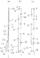
以下のような手順で、この発明の接続用金物1を製造する。
The
(1) 材厚t1 (3.5mm程度)のパイプ材(長さ440mm程度)の一側2a(34mm程度。全体の5分の4程度)をプレスにて内面が密着するように押圧して板状部3(=厚さt2)を形成し、他側2b(残部)を筒状部10(=厚さt1)とする。続いて、あるいは同時に、板状部3と筒状部10との境界付近を、板状部3の厚さ方向(図1(a)矢示22方向)に屈曲して屈曲部20を形成して、板状部3の中心軸7と筒状部10の中心軸17とをずらす。板状部3と筒状部10とは屈曲部20を介して一体に構成されている。
(1) Press one side 2a (about 34 mm, about 4/5 of the whole) of the pipe material (about 440 mm) of material thickness t 1 (about 3.5 mm) with a press so that the inner surface is in close contact. The plate-like portion 3 (= thickness t 2 ) is formed, and the other side 2b (remaining portion) is defined as the tubular portion 10 (= thickness t 1 ). Subsequently, or simultaneously, the
(2) 続いて、板状部3に、複数の透孔6、6を千鳥状に穿設する(図1(b)(c))。この場合、透孔6、6の配列は千鳥状が望ましいが、平行状に配置することもできる(図示していない)。
(2) Subsequently, a plurality of through
(3) また、(2)と同時に又は前後して、筒状部10の先端を広げて拡径部13を形成すると共に、筒状部10の内面12に螺糸(ねじ)を形成して、螺筒状部(筒状部)10とする。この状態で、螺筒状部10の一面側の外面11(拡径部13を含む)は板状部3の一面4の延長面4aよりも他面5側に位置している。
(3) Also, at the same time or before and after (2), the tip of the
(4) この状態で、全体を塗装又はメッキ処理をして、この発明の接続用金物1を構成する(図1、図2)。ここで、t2は元の材厚t1の2倍の厚さになっている。即ち、螺筒状部10の肉厚t1、板状部3の肉厚t2とした場合、
t2=2×t1
で構成されている。
(4) In this state, the whole is painted or plated to form the
t 2 = 2 × t 1
It consists of
(5) 他の実施態様
前記実態様において、予め内面に螺糸を形成したパイプ材を使用して、このパイプ材をプレスすることもできる。この場合には、前記(3)の螺糸を形成する工程を省略し、また予め塗装又はメッキを施したパイプ材を使用すれば、最後の塗装又はメッキの工程を省略することもできる。
また、前記実施態様において、螺筒状部10及び板状部3の長さ、厚さは、求める耐力により適宜選択して形成する。
また、前記実施態様において、塗装又はメッキ処理は最後が望ましいが、求める性能により、任意である。
また、接続用金物1の製造方法は、上記方法に限らず、同様の構造が製造できれば任意である。
(5) Other Embodiments In the above embodiment, the pipe material can be pressed using a pipe material in which a thread is formed on the inner surface in advance. In this case, the step of forming the thread of (3) can be omitted, and the last painting or plating step can be omitted if a pipe material that has been previously painted or plated is used.
Moreover, in the said embodiment, the length and thickness of the screw-shaped
Moreover, in the said embodiment, although the last of a coating or plating process is desirable, it is arbitrary according to the performance calculated | required.
Moreover, the manufacturing method of the
図3に基づきこの発明の耐震補強構造について説明する。 The earthquake-proof reinforcement structure of this invention is demonstrated based on FIG.
(1) コンクリート製の基礎25の上面26に土台30が固定され、土台30の上に柱32が立設固定されている。柱32及び土台30の外壁側に胴縁34を介して、外壁材35が固定してあり、既設建物37を構成する(図3(a))。土台30と基礎25とはアンカーボルトで固定され、あるいは土台30と基礎25と柱32とはいわゆるホールダウン金物で固定されるなど、通常の手段により固定されている(図示していない)。
(1) A
また、柱32の上方は通常の構造で、屋根まで構成され、また床や内壁をはじめ必要な内装が施されている(図示していない)。図中38は水切りである。
Further, the upper part of the
また、コンクリート製の基礎25は土台30の高さや大きさに対応した本体部25aと本体部25aの下端に幅広に形成した脚部25bとから構成されている。この既設建物37では、基礎25は充分な耐力を有する構造で構成されているが、土台30をはじめ上方の構造物と基礎25との接合が充分耐震強度を得ていないとする。
The
(2) 基礎25の本体部25aの側面27に、ホールダウン金物40の板部41を当てて、グリップアンカー44、44で基礎25と板部41とを固定する。この状態で、ホールダウン金物40のU字状のボルト挿通部42は上下に開口している。
(2) The plate portion 41 of the hole-down hardware 40 is applied to the
(3) (2) と前後して又は同時に、外壁材35の外面に、接続用金物1の板状部3を当接し、螺筒状部10を土台30の下面31より下方に位置させ、螺筒状部10の開口は下方に向けられている。続いて、板状部3の各透孔6、6から角ビットビス48、48を、柱32及び土台30に向けて打ち込み、「板状部3」と「柱32及び土台30」とを固定する。この際、板状部3の透孔6、6の少なくとも1つが土台30に位置に、土台30に角ビットビス48が打ち込まれるようにすることが望ましい。
(3) Before or after or simultaneously with (2), the plate-
(4) 続いて、ホールダウン金物40のボルト挿通部42に下方から六角ボルト46を挿入し(ボルト挿通部42に、六角ボルト46がゆるく挿入されている)、六角ボルト46の頭部47をボルト挿通部42の下縁42aに係止して、先端部(螺糸部)を接続用金物1の螺筒状部10に螺合緊結する。これにより、六角ボルト46を介して、「柱32及び土台30に固定された接続用金物1」と「基礎25に固定されたホールダウン金物40」とが強固に固定され、「土台30及び柱32と基礎25」とが強固に接続され、耐震補強構造50が構築される(図3(b))。この際、螺筒状部10に拡径部13が形成されているので、六角ボルト46を挿入しやすい。
(4) Subsequently, the
この際、接続用金物1の螺筒状部10が屈曲部20を介して、中心軸7、17がずらしてあるので、螺筒状部10が外壁材35や土台30、基礎25などに当接するなどして、板状部3を外壁材35へ強固に取付けができると共に、取付け作業に支障を与えることもない。また、螺筒状部10が基礎25の側面27から確実に浮いた状態となるので、六角ボルト46の取付け作業が確実にでき、ホールダウン金物40と接続用金物1とを確実に固定できる。
At this time, since the
(5) 前記の接続用金物1は、総ての柱32、32に設置することが望ましいが、求める性能によっては、選択した柱32、32にのみ適用することもできる。また、接続用金物1の材厚大きさ、ホールダウン金物40の大きさ強度、求める増強される分の強度により算定する。不均衡な引抜力が発生しないように、外周方向で所定の間隔で配置する。
(5) The
(6) 他の実施例
前記実施例において、外壁材35の外面に接続用金物1を当接して、外壁を貫通させて角ビットビスを柱32などへ打ち込んだが、外壁材35及び胴縁34の固定が不十分で強度が不足している場合には、外壁材35及び胴縁34を取り外し、接続用金物1の板状部を「柱32の側面32a及び土台30の側面30a」に当接することもできる(図示していない)。この場合にも、接続用金物1の螺筒状部10が屈曲部20を介して、中心軸7、17がずらしてあるので、接続用金物1の螺筒状部10が基礎25の側面27に当接しないので、外壁材35に固定する場合と同様に、強固に取り付けられ、かつ容易に作業ができる。
(6) Other Embodiments In the above-described embodiment, the
また、この場合には、新たに胴縁34、外壁材35を取り付けるので、接続用金物1の板状部3が外壁材に35、35に隠れるので、更に外観上の見栄えが良くなる。
In this case, since the
また、前記実施例において、ホールダウン金物40を使用したが、基礎25の側面27又は脚部25bに固定でき、かつ接続用金物1の螺筒状部10と接合できる構造であれば、他の金物類を使用することもできる(図示していない)。
Moreover, in the said Example, although the hole down metal fitting 40 was used, if it is a structure which can be fixed to the
また、この実施例を、新設の構造物の同様な部位に適用することもできる。 In addition, this embodiment can be applied to a similar part of a new structure.
次ぎに、図4に基づき、他の耐震補強構造の実施を説明する。この耐震補強構造50では、基礎25に鉄筋が不足する等、基礎25の強度が充分でない場合に適用する実施例である。
Next, the implementation of another seismic reinforcement structure will be described based on FIG. This
(1) 実施例1と同様に、既設建物が構成されている。
即ち、コンクリート製の基礎25の上面26に土台30が固定され、土台30の上に柱32が立設固定されている。柱32及び土台30の外壁側に胴縁34を介して、外壁材35が固定してあり、既設建物37を構成する(図3(a))。土台30と基礎25とはアンカーボルトで固定され、あるいは土台30と基礎25と柱32とはいわゆるホールダウン金物で固定されるなど、通常の手段により固定されている(図示していない)。
また、柱32の上方は通常の構造で、屋根まで構成され、また床や内壁をはじめ必要な内装が施されている(図示していない)。図中38は水切りである。
また、コンクリート製の基礎25は土台30の高さや大きさに対応した本体部25aと本体部25aの下端に幅広に形成した脚部25bとから構成されている。
(1) Similar to the first embodiment, an existing building is configured.
That is, the
Further, the upper part of the
The
(2) 接続用金物1の設置位置(即ち、アンカーボルト52の埋設位置)に合わせて、基礎25の脚部25bに埋設用穴20を空ける。この場合、必要なアンカーボルト52の埋設深さを確保するために、脚部25bを貫通する場合もある。
(2) The embedding
(3) 続いて、接続用金物1の螺筒状部10にアンカーボルト52の上端部53を、所定のかみ合わせ分だけ螺合して、接続用金物1とアンカーボルト52とを連結する。ここで、使用するアンカーボルト52は下端部をS字状に屈曲してあり、短い埋設深さでも引抜強さを強化できるようにしてある。
(3) Subsequently, the
(4) 続いて、アンカーボルト52の下端部54を埋設穴56に入れると共に、接続用金物1の板状部3を外壁材35に当接する。螺筒状部10を土台30の下面31より下方に位置させ、螺筒状部10の開口縁14は下方に向けられている。また、アンカーボルト52の下端部54を基礎25の構造鉄筋57あるいは、新たに埋設穴56内に設置した構造鉄筋57、57に係止することが望ましい(図4(b))。
(4) Subsequently, the
(5) 続いて、前記実施例1と同様に、板状部3の各透孔6、6から角ビットビス48、48を、柱32及び土台30に向けて打ち込み、「板状部3」と「柱32及び土台30」とを固定する。この際、板状部3の透孔6、6の少なくとも1つが土台30に位置し、土台30に角ビットビス48が打ち込まれるようにすることが望ましい。
(5) Subsequently, in the same manner as in the first embodiment, the square bit screws 48 and 48 are driven from the through
(6) 続いて、あるいは(5) の前に、埋設穴56内にコンクリートを打設する。コンクリートが固化発現したならば、この発明の耐震補強構造50を構成する(図4(b))。
(6) Next, or before (5), place concrete in the buried
(7) 他の実施例
前記実施例において、実施例1と同様に、外壁材35及び胴縁34の固定が不十分で強度が不足している場合には、外壁材35及び胴縁34を取り外し、接続用金物1の板状部を「柱32の側面32a及び土台30の側面30a」に当接することもできる(図示していない)。この場合にも、アンカーボルトは鉛直に配置されるように、埋設穴56の位置を調節する。
(7) Other Embodiments In the above embodiment, as in the first embodiment, when the
また、前記実施例において、埋設穴56を形成したが、基礎25の脚部25bに構造鉄筋が大幅に不足し、あるいは構造鉄筋が入っていない場合には、基礎25の脚部25b全体を除去して、掘り起こし、必要数の構造鉄筋57、57を追加して配置してコンクリートを打設する(図示していない)。
In the above embodiment, the buried
また、この実施例を、新設の構造物の同様な部位に適用することもできる。 In addition, this embodiment can be applied to a similar part of a new structure.
図5、図6に基づきこの発明の他の実施例を説明する。この実施例は、改修補強又は新設構造物の補強に関する実施例である。 Another embodiment of the present invention will be described with reference to FIGS. This embodiment is an embodiment related to reinforcement of reinforcement or reinforcement of a new structure.
(1) この実施例では、前記のように構成した接続用金物1と、螺筒状部10の螺子を逆螺子とした接続用金物1aとを組み合わせて使用する(図5)。
また、固定部材として、棒状の基部61の両側に螺子部62、62aを形成した螺杆60を使用する。螺子部62aは、螺糸部62に対して逆螺子に形成されている。また、基部61の両端部で、螺子部62、62aの内側に、扁平部63、63を夫々形成してある(図5(b))。
(1) In this embodiment, the
Moreover, the
(2) 柱32と梁65、65aが接合された接合部で、柱32に軸方向と直角な方向(梁の軸方向)に貫通孔33を穿設する。貫通孔33に螺杆60の基部61を貫通させ、柱32の両側(梁65、65a)に螺子部62、62aを位置させる。
(2) A through-
(3) 続いて、梁65側(螺子部62側)に接続用金物1を、梁65a側(螺子部62a側)に接続用金物1aを位置させ、螺杆60の螺糸部62を接続用金物1の螺筒状部10を螺合し、螺杆60の螺糸部62を接続用金物1の螺筒状部10を螺合する。この際、螺糸部62(又は螺筒状部10)と螺糸部62a(又は螺筒状部10a)とを逆螺子としてあるので、螺杆60を一側に回転することで、両側を一度に締めることができる。また、接続用金物1、1aを押さえて、扁平部63、63にスパナなどを挟み回転させることにより、特殊な工具を使用することなく、螺子部62、62aと螺筒状部10、10aとを容易に締めることができる。
(3) Subsequently, the
(4) 続いて、各接続用金物1、1aの板状部3を、梁65、65aの側面66、66に当接させ、前記実施例と同様に、透孔6、6にビス類を打って、各接続用金物1、1aを梁65、65aに固定し、耐震補強構造50を構成する(図5(a)(b))。
(4) Subsequently, the plate-
(5) 前記実施例において、いわゆる両引きで接続用金物1、1aを使用したが、いわゆる羽子板ボルト用の羽子板と同様に、片引きで使用することもできる(図6)。柱32に対して、平面で3方に梁65、65a、65bが接合された接合部で(図6(b))、一つの梁65aの側面66に貫通孔67を穿設し、梁65bの側面66に、接合用金物1の板状部3を位置させ、螺筒状部10の開口を貫通孔67に向けて配置する。続いて、貫通孔66に、六角ボルト47に座金49を付けて、螺子部47aを挿通して、螺筒状部10に螺合する。ビスで板状部3を梁65bの側面66に固定すると共に、六角ボルト47を緊結して、六角ボルト47を接続用金物1に固定する。以上のようにして、耐震補強構造50を構築する(図6(a)(b))。
(5) In the above-described embodiment, the
(6) また、前記実施例において、柱と梁の接合部に適用したが、柱以外の縦構造材と梁以外の横架材との接合に同様に適用することができる(図示していない)。また、前記実施例において、柱32(縦構造材)に貫通孔を形成したが、梁65(横架材)に貫通孔を形成して螺杆60を挿通して、柱32(縦構造材)の側面に接続用金物1、1aの板状部3、3を固定することもできる(図示していない)。
(6) In the above embodiment, the present invention is applied to the joint between the column and the beam. However, the present invention can be similarly applied to the joint between the vertical structural member other than the column and the horizontal member other than the beam (not shown). ). In the above embodiment, the through hole is formed in the column 32 (vertical structure material). However, the through hole is formed in the beam 65 (horizontal material) and the
(7) この実施例は既設の構造物の補強又は新設の構造物の補強のいずれにも適用することができる。 (7) This embodiment can be applied to either reinforcement of an existing structure or reinforcement of a new structure.
1 接続用金物
2a 接続用金物の一側
2b 接続用金物の他側
3 板状部
4 板状部の一面
4a 一面の延長面
5 板状部の他面
6 透孔
7 板状部の中心軸
10、10a 螺筒状部(筒状部)
11 螺筒状部の一面4側の外面
12 螺筒状部の内面
13 螺筒状部の拡径部
14 螺筒状部の開口縁
17 螺筒状部の中心軸
20 屈曲部
25 基礎
26 基礎の上面
27 基礎の側面
30 土台
30a 土台の側面
32 柱
32a 柱の側面
33 柱の貫通孔
34 胴縁
35 外壁材
37 既設建物
38 水切り
40 ホールダウン金物
41 ホールダウン金物の板部
42 ホールダウン金物のボルト挿通部
44 クリップアンカー
46 六角ボルト
48 角ビットビス
50 耐震補強構造
52 アンカーボルト
53 アンカーボルトの上端部
54 アンカーボルトの下端部
56 埋設穴
60 螺杆(固定手段)
61 螺杆の基部
62、62a 螺杆の螺子部
63 螺杆の扁平部
65、65a、65b 梁
66 梁の側面
67 梁の貫通孔
DESCRIPTION OF
DESCRIPTION OF
61 Screw bases 62,
Claims (5)
(1) パイプ材料の一側を潰して前記板状部を形成し、該パイプ材料の他側の内面に螺糸を形成して螺筒状部を形成した。
(2) 前記板状部の軸と前記螺筒状部の軸とをずらして形成し、前記板状部の一面の延長面より前記螺筒状部が前記板上部の他面側に位置させた。 A metal fitting for connection having a plate-like part with a through hole formed on one side and a screw-like part with a screw hole formed on the inner surface on the other side has the following structure. Hardware for connection.
(1) One side of the pipe material was crushed to form the plate-like part, and a thread was formed on the inner surface of the other side of the pipe material to form a screw-like part.
(2) The axis of the plate-like portion and the axis of the screw-like portion are formed so as to be shifted, and the screw-like portion is positioned on the other surface side of the upper portion of the plate from the extended surface of one surface of the plate-like portion. It was.
(1) 前記螺筒状部の肉厚t1、前記板状部の肉厚t2とした場合、
t2=2×t1
とした。
(2) 前記板状部の軸と前記螺筒状部の軸とをずらして形成し、前記板状部の一面の延長面より前記螺筒状部が前記板上部の他面側に位置させた。 A metal fitting for connection having a plate-like part with a through hole formed on one side and a screw-like part with a screw hole formed on the inner surface on the other side has the following structure. Hardware for connection.
(1) When the thickness t 1 of the screw-like portion and the thickness t 2 of the plate-like portion are set,
t 2 = 2 × t 1
It was.
(2) The axis of the plate-like portion and the axis of the screw-like portion are formed so as to be shifted, and the screw-like portion is positioned on the other surface side of the upper portion of the plate from the extended surface of one surface of the plate-like portion. It was.
(1) パイプ材料の一側を潰して前記板状部を形成し、該パイプ材料の他側の内面に螺糸を形成して螺筒状部を形成した。前記板状部の軸と前記螺筒状部の軸とをずらして形成し、前記板状部の一面の延長面より前記螺筒状部が前記板状部の他面側に位置させた。前記板状部に透孔を形成して、接続用金物を構成する。
(2) 既設建物において「予め外壁を取り除いた前記柱及び/又は土台」あるいは「前記外壁の外面に」、前記接続用金物の板状部を当接し、前記螺筒状部を下方に向けて設置し、前記透孔からビス類を打ち、前記板状部を前記土台及び/又は柱に固定する。
(3) 前記基礎に固定した固定手段からの螺杆を前記接続用金物の螺筒状部に螺合緊結した。 A reinforced structure for a building that is seismically reinforced in the following manner in a wooden structure in which a pillar is erected by forming a foundation on a concrete foundation.
(1) One side of the pipe material was crushed to form the plate-like part, and a thread was formed on the inner surface of the other side of the pipe material to form a screw-like part. The axis of the plate-like portion and the axis of the screw-like portion are formed so as to be shifted, and the screw-like portion is positioned on the other surface side of the plate-like portion from the extended surface of one surface of the plate-like portion. A through hole is formed in the plate-like portion to constitute a connection hardware.
(2) In the existing building, “the pillar and / or base from which the outer wall has been removed beforehand” or “to the outer surface of the outer wall”, abut the plate-like portion of the connection hardware, and face the screw-like portion downward. It installs, hits screws from the said through-hole, and fixes the said plate-shaped part to the said base and / or a pillar.
(3) The screw from the fixing means fixed to the foundation was screwed and fastened to the screw-like portion of the connection hardware.
(1) パイプ材料の一側を潰して前記板状部を形成し、該パイプ材料の他側の内面に螺糸を形成して螺筒状部を形成した。前記板状部の軸と前記螺筒状部の軸とをずらして形成し、前記板状部の一面の延長面より前記螺筒状部が前記板状部の他面側に位置させた。前記板状部に透孔を形成して、接続用金物を構成する。
(2) 「柱をはじめとした縦構造材」又は「土台や梁をはじめとした横架材」のいずれか一方を両側にネジ部を形成した固定手段を貫通して配置し、
前記他方の側面に前記接続用金物の板状部を当接し、前記螺筒状部を前記固定手段のネジ部に向けて設置し、前記ネジ部を螺筒状部に螺合すると共に、
前記透孔からビス類を打ち、前記板状部を前記縦構造材又は横架材に固定する。 A reinforced structure for a building that is seismically reinforced in the following manner in a wooden structure in which a pillar is erected by forming a foundation on a concrete foundation.
(1) One side of the pipe material was crushed to form the plate-like part, and a thread was formed on the inner surface of the other side of the pipe material to form a screw-like part. The axis of the plate-like portion and the axis of the screw-like portion are formed so as to be shifted, and the screw-like portion is positioned on the other surface side of the plate-like portion from the extended surface of one surface of the plate-like portion. A through hole is formed in the plate-like portion to constitute a connection hardware.
(2) Arrange one of “vertical structure materials including pillars” or “horizontal materials such as foundations and beams” through the fixing means with threaded parts on both sides,
The plate-like portion of the connection hardware is brought into contact with the other side surface, the screw-like portion is installed toward the screw portion of the fixing means, and the screw portion is screwed into the screw-like portion,
Screws are hit through the through holes, and the plate-like portion is fixed to the vertical structural member or horizontal member.
Priority Applications (1)
| Application Number | Priority Date | Filing Date | Title |
|---|---|---|---|
| JP2006289275A JP4974023B2 (en) | 2005-10-25 | 2006-10-24 | Connection hardware, building reinforcement structure |
Applications Claiming Priority (3)
| Application Number | Priority Date | Filing Date | Title |
|---|---|---|---|
| JP2005310231 | 2005-10-25 | ||
| JP2005310231 | 2005-10-25 | ||
| JP2006289275A JP4974023B2 (en) | 2005-10-25 | 2006-10-24 | Connection hardware, building reinforcement structure |
Publications (2)
| Publication Number | Publication Date |
|---|---|
| JP2007146631A true JP2007146631A (en) | 2007-06-14 |
| JP4974023B2 JP4974023B2 (en) | 2012-07-11 |
Family
ID=38208347
Family Applications (1)
| Application Number | Title | Priority Date | Filing Date |
|---|---|---|---|
| JP2006289275A Active JP4974023B2 (en) | 2005-10-25 | 2006-10-24 | Connection hardware, building reinforcement structure |
Country Status (1)
| Country | Link |
|---|---|
| JP (1) | JP4974023B2 (en) |
Cited By (2)
| Publication number | Priority date | Publication date | Assignee | Title |
|---|---|---|---|---|
| JP2013194414A (en) * | 2012-03-19 | 2013-09-30 | Hokoku Eng Kk | Earthquake strengthening structure and earthquake strengthening of wooden house |
| JP2018087416A (en) * | 2016-11-28 | 2018-06-07 | 株式会社アーネストワン | Hold-down hardware |
Citations (1)
| Publication number | Priority date | Publication date | Assignee | Title |
|---|---|---|---|---|
| JP2005344500A (en) * | 2004-11-25 | 2005-12-15 | Nippon Steel Corp | Joint fitting between members as well as joint structure and joining method for vertical frame members of upper and lower floors |
-
2006
- 2006-10-24 JP JP2006289275A patent/JP4974023B2/en active Active
Patent Citations (1)
| Publication number | Priority date | Publication date | Assignee | Title |
|---|---|---|---|---|
| JP2005344500A (en) * | 2004-11-25 | 2005-12-15 | Nippon Steel Corp | Joint fitting between members as well as joint structure and joining method for vertical frame members of upper and lower floors |
Cited By (2)
| Publication number | Priority date | Publication date | Assignee | Title |
|---|---|---|---|---|
| JP2013194414A (en) * | 2012-03-19 | 2013-09-30 | Hokoku Eng Kk | Earthquake strengthening structure and earthquake strengthening of wooden house |
| JP2018087416A (en) * | 2016-11-28 | 2018-06-07 | 株式会社アーネストワン | Hold-down hardware |
Also Published As
| Publication number | Publication date |
|---|---|
| JP4974023B2 (en) | 2012-07-11 |
Similar Documents
| Publication | Publication Date | Title |
|---|---|---|
| US6367205B2 (en) | Anchor for a structural tie-down apparatus | |
| CN111868332A (en) | Column mounting bracket | |
| JP2859117B2 (en) | Steel column base anchoring structure | |
| JP4585595B2 (en) | Seismic reinforcement structure for wooden houses and seismic reinforcement method for wooden houses | |
| KR101019588B1 (en) | Device for preventing buoyance in hollow concrete slab | |
| JP4672459B2 (en) | Building reinforcement method | |
| JP4974023B2 (en) | Connection hardware, building reinforcement structure | |
| JP7378187B1 (en) | Lag screw bolt installation jig and installation method | |
| JP2006132313A (en) | Joint structure of foundation and frame | |
| JP6965663B2 (en) | Building foundation repair method and building foundation structure | |
| JP2007218043A (en) | Joint securing structure of wooden building, fitting for joint securing structure, column base structure, fitting for column base structure, column-beam joint structure, and fitting for column-beam joint structure | |
| JP2010106516A (en) | Portal frame structure of wooden building | |
| US20080295444A1 (en) | Structural Tie-Down Apparatus | |
| JP5756659B2 (en) | Anchor bolt advance yield type attracting metal and method for seismic reinforcement of large-scale wooden buildings using the attracted metal | |
| JP2006193996A (en) | Fixing structure of column | |
| JP4654674B2 (en) | How to install seismic reinforcement brackets for wooden buildings | |
| RU2106459C1 (en) | Method and device for fastening facing tiles | |
| JP2013213356A (en) | Metal fitting and reinforcing structure | |
| JP2009209646A (en) | Anti-seismic reinforcing method and aseismatic reinforcement structure of existing wooden house | |
| JP6993639B2 (en) | Reinforcement structure and reinforcement method for concrete structures, reinforcement reinforcement runner for both structure connection | |
| JP2006063799A (en) | Building reinforcing hardware | |
| JP2010077645A (en) | Joint structure in wooden building | |
| JPH10183923A (en) | Assembled structure of handrail | |
| JP3241606B2 (en) | Reinforcement structure of existing wooden building and anchor used for it | |
| JP2001159192A (en) | Lifting prevention structure of column with wall |
Legal Events
| Date | Code | Title | Description |
|---|---|---|---|
| A621 | Written request for application examination |
Free format text: JAPANESE INTERMEDIATE CODE: A621 Effective date: 20090828 |
|
| TRDD | Decision of grant or rejection written | ||
| A01 | Written decision to grant a patent or to grant a registration (utility model) |
Free format text: JAPANESE INTERMEDIATE CODE: A01 Effective date: 20120131 |
|
| A01 | Written decision to grant a patent or to grant a registration (utility model) |
Free format text: JAPANESE INTERMEDIATE CODE: A01 |
|
| R155 | Notification before disposition of declining of application |
Free format text: JAPANESE INTERMEDIATE CODE: R155 |
|
| A61 | First payment of annual fees (during grant procedure) |
Free format text: JAPANESE INTERMEDIATE CODE: A61 Effective date: 20120330 |
|
| R150 | Certificate of patent or registration of utility model |
Ref document number: 4974023 Country of ref document: JP Free format text: JAPANESE INTERMEDIATE CODE: R150 Free format text: JAPANESE INTERMEDIATE CODE: R150 |
|
| FPAY | Renewal fee payment (event date is renewal date of database) |
Free format text: PAYMENT UNTIL: 20150420 Year of fee payment: 3 |
|
| R250 | Receipt of annual fees |
Free format text: JAPANESE INTERMEDIATE CODE: R250 |
|
| R250 | Receipt of annual fees |
Free format text: JAPANESE INTERMEDIATE CODE: R250 |
|
| R250 | Receipt of annual fees |
Free format text: JAPANESE INTERMEDIATE CODE: R250 |
|
| R250 | Receipt of annual fees |
Free format text: JAPANESE INTERMEDIATE CODE: R250 |
|
| R250 | Receipt of annual fees |
Free format text: JAPANESE INTERMEDIATE CODE: R250 |
|
| R250 | Receipt of annual fees |
Free format text: JAPANESE INTERMEDIATE CODE: R250 |
|
| R250 | Receipt of annual fees |
Free format text: JAPANESE INTERMEDIATE CODE: R250 |
|
| R250 | Receipt of annual fees |
Free format text: JAPANESE INTERMEDIATE CODE: R250 |
|
| R250 | Receipt of annual fees |
Free format text: JAPANESE INTERMEDIATE CODE: R250 |
|
| R250 | Receipt of annual fees |
Free format text: JAPANESE INTERMEDIATE CODE: R250 |