JP2007146346A - Color-changing device of circular needle loom - Google Patents
Color-changing device of circular needle loom Download PDFInfo
- Publication number
- JP2007146346A JP2007146346A JP2005345930A JP2005345930A JP2007146346A JP 2007146346 A JP2007146346 A JP 2007146346A JP 2005345930 A JP2005345930 A JP 2005345930A JP 2005345930 A JP2005345930 A JP 2005345930A JP 2007146346 A JP2007146346 A JP 2007146346A
- Authority
- JP
- Japan
- Prior art keywords
- cam
- yarn
- plate
- connecting rod
- movable
- Prior art date
- Legal status (The legal status is an assumption and is not a legal conclusion. Google has not performed a legal analysis and makes no representation as to the accuracy of the status listed.)
- Granted
Links
Images


Landscapes
- Knitting Machines (AREA)
Abstract
Description
本発明は、針織機の変色装置に関するものであり、特別に円形針織機(circular knitting machine)に使用した変色装置である。 The present invention relates to a color changing device for a needle loom, and is a color changing device specially used for a circular knitting machine.
円形針織機における変色装置の技術は、以前より人々に熟知されているとおりである。例えば既に認可公開されている特許文献1「STRIPING APPARATUS FOR CIRCULAR KNITTING MACHINES」及び特許文献2「STRIPING SYSTEM FOR CIRCULAR KNITTING MACHINE」にはそれぞれ、異なる糸を針織機の織針に用いた変色装置が記載されている。また、やはり認可された特許文献3「CIRCULAR KNITTING MACHINE STRIPER CONTROL SYSTEM」には、変色装置中に用いた制御器20が記載されている。
The technology of the color changing device in the circular needle loom is as familiar to people as before. For example, in
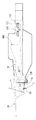
前記特許文献3の中に記載された変色装置の構造は図1から図4に示すとおりであるが、それは、糸交換板と可動刀板11及び糸交換板と可動刀板を駆動する駆動部位(図中未示)により構成されている。糸交換板は通常、不作動位置に位置し、可動刀板は本体に収められている。並びに、糸は、鈎部によって前縁に挟み込まれる。糸供給が開始すると、糸交換板は駆動部位によって押し出され、糸交換板の先端は外側に延伸する。(図2参照)同時に糸交換板の後端は可動刀板11の第一止め金にぶつかり、連動する可動刀板によって図3の左方向に移動、糸交換板が外部の糸供給位置にまで達すると、糸Yは可動刀板の鈎部から離れる。(図3参照)当然ながら、鈎部から離れる以前、糸Yは既に糸交換板によって糸挿入位置に送られており、並びに織針(needle)に引っ掛けられている為、針織作業は進行している。
The structure of the color changing device described in
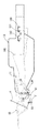
最後に、別の糸に取換える場合、先に糸供給位置にまで延伸した糸交換板10は駆動部位により通常位置(図1の位置)に戻され、糸交換板は図4の右側方向に移動する中、糸交換板突出部が可動刀板の第二止め金112にぶつかり、続いて可動刀板を連動して右側方向に移動、通常位置に戻った後、可動刀板の鈎部が本体の前縁箇所で糸Yを切断するのと同時に糸Yの後端を本体12の前縁に挟み込む。
Finally, when replacing with another yarn, the
しかしながら、一般に言えば、この種の変色装置は数種の異なる色の糸を提供でき、例えば、四色変色装置であるなら、四組の相互に並列する糸交換板及び可動刀板により構成されており、それぞれが四種の糸の交換を行う。六色変色装置もまた同様の構造で、糸の数が多くなればなるほど変色装置の幅は広くなる。前記特許文献3の中に記載されている変色装置は可動刀板のが糸交換板を連動する構造で、糸交換板が駆動部位によって通常位置方向に移動する場合、可動刀板の第二止め金にぶつかるまでに若干遅れ時間差が生じ、この種の同一駆動部位に連動される構造では、可動刀板の糸切断時間が若干遅れてしまう。糸取換え時、例えば1号糸と6号糸のように新旧二本の糸の位置間隔が離れている場合、この動作の時間差も増え、糸の放出時間も遅くなり、糸の後端がまだ可動刀板に挟まれている状況の下、先に引っ張られ切断されて糸末端が残留することになる。(図2)また、この引っ張られて切断された糸末端はその後放されて落下すると、針織運動に伴って織物の中へ混入することも容易に発生し、織物品質に影響することになる。
However, generally speaking, this type of discoloring device can provide several different colors of threads, for example, if it is a four-color discoloring device, it is composed of four pairs of thread changing plates and movable blades that are parallel to each other. Each of them exchanges four types of yarn. The six-color changing device also has the same structure, and the width of the changing device becomes wider as the number of yarns increases. The color changing device described in
本発明の目的は、糸切れ端の発生を防ぎ織物の品質を改善する、円形針織機に使用する変色装置を提案することにある。 An object of the present invention is to propose a color changing device for use in a circular needle loom that prevents the occurrence of yarn breakage and improves the quality of the fabric.
本発明の円形針織機の変色装置は、異なるカムを用いてそれぞれ糸交換板と可動刀板を駆動する為、糸取換え時、二本の糸の間隔が比較的開いている場合であっても、異なるカムの動作時間を調節、制御することによって旧糸を素早く元に戻して切断、その後、新糸が引っ張られて切断される前にその糸後端を可動刀板箇所から放すという特徴を持つ。それにより、糸が引っ張られて切断されるのを防ぐ為、糸切れ端の発生を妨げ、織物の品質向上に効果的である。 The color changing device for the circular needle loom according to the present invention drives the thread change plate and the movable blade plate using different cams, respectively, and therefore, when replacing the thread, the distance between the two threads is relatively open. Also, the operating time of different cams is adjusted and controlled so that the old thread can be quickly restored and cut, and then the trailing end of the thread is released from the movable knife plate before the new thread is pulled and cut. have. Thereby, since the yarn is prevented from being pulled and cut, the occurrence of yarn breakage ends is prevented, which is effective in improving the quality of the fabric.
請求項1の発明は、円形針織機の変色装置は、次の構成要素(a)(b)(c)を含むことを特徴とし、
(a)制御器は、円形針織機の針織部に沿って運行する選択器により連動され、
(b)糸供給部位は、二つの部分により構成され、糸交換板、第一連結棒及び第二連結棒を含む第一部分は、糸Yを捉糸位置まで送り、可動刀板、駆動連結棒を含む第二部分は、指令待ち状態の下、糸の末端を挟み込み、また、糸交換時に旧糸を切断することにより織物から離し元の指令待ち状態に戻し、
(c)駆動部位は、選択器と同時に円形針織機の針織部に沿って運行し、第一組カム第二組カムによって構成され、糸交換板と可動刀板はそれぞれ第一組カムと第二組カムにより連動され、第一組カムと第二組カムは、前方カム(forward cam)と後方カム(backward cam)を含み、第一組カム中の前方カムは糸交換板を外部の作動位置(external position)に押し出す働きを、第二組カム中の前方カムは可動刀板を外部の放糸位置(release positon)に押し出す働きを持ち、また、第一組カム中の後方カムは糸交換板を通常の不作動位置(normal positon)に戻し、第二組カムの後方カムは可動刀板を通常の挟糸位置(holding position)に戻すことを特徴とする円形針織機の変色装置としている。
請求項2の発明は、前記第一連結棒先端両側にはそれぞれ上方に突出した前方突出部及び下方に突出した後方突出部を突設、この前方突出部は第一組カム中の前方カムにより連動され、後方突出部は第一組カムの後方カムに連動され、また、後端が第二連結棒の後端に嵌合された糸交換板は、第二連結棒の連動を受け通常の不作動位置(normal position)と、外部に延伸した作動位置(external position)間を前後運動することを特徴とする請求項1記載の円形針織機の変色装置としている。
請求項3の発明は、前記可動刀板後端は駆動連結棒後端に嵌合され、その駆動連結棒51先端両側にはそれぞれ上向きの前方突出部、及び下向きの後方突出部が突設され、その前方突出部は第二組カム中の前方カムによって連動され、後方突出部511は第二組カム中の後方カムによって連動され、また、それらに連動される可動刀板は通常の挟糸位置(holding position)と外部に延伸した放糸位置(release position)間の前後運動をすることを特徴とする請求項1記載の円形針織機の変色装置としている。
請求項4の発明は、前記第二組カム中の前記前方カムは、固定カムと可動式カムを含み、第一斜面は固定カムの先端に位置し、また可動式カム74は第二斜面を具え、固定カムと可動式カムは異なる高さに位置し、また、前記糸供給部位の数個の駆動連結棒は、高低の異なる二種の前方突出部を具え、比較的高さの高い前方突出部は固定カムの第一斜面により押し動かされ、比較的高さの低い前方突出部は可動式カムの第二斜面によって押し動かされることを特徴とする請求項1記載の円形針織機の変色装置としている。
請求項5の発明は、前記可動式カムは、ボルトで前方カムに固定され、ボルトを緩めると、固定カムに相対する可動式カムの位置を調節可能であることを特徴とする請求項4の円形針織機の変色装置としている。
The invention of
(A) The controller is linked by a selector operating along the needle weaving part of the circular needle loom,
(B) The yarn supply part is composed of two parts, and the first part including the yarn exchange plate, the first connecting rod and the second connecting rod feeds the yarn Y to the catching position, and the movable blade plate and the drive connecting rod. The second part including the pinch the end of the yarn under the command waiting state, and by cutting the old yarn at the time of yarn replacement, it is separated from the fabric and returned to the original command waiting state,
(C) The drive part operates along the needle weaving portion of the circular needle loom simultaneously with the selector, and is constituted by the first set cam and the second set cam, and the thread change plate and the movable blade plate are the first set cam and the first set cam, respectively. Interlocked by two sets of cams, the first set cam and the second set cam include a forward cam and a backward cam, and the front cam in the first set cam operates the thread change plate externally. The front cam in the second set cam has the function of pushing out the movable blade to the external release position, and the rear cam in the first set cam has the function of pushing out to the position (external position). The replacement plate is returned to the normal normal position, and the rear cam of the second set of cams returns the movable blade plate to the normal holding position. It is discoloration device circular needle loom according to symptoms.
According to a second aspect of the present invention, a front projecting portion projecting upward and a rear projecting portion projecting downward are provided on both sides of the tip of the first connecting rod, and the front projecting portion is formed by a front cam in the first set cam. The thread change plate with the rear projecting portion interlocked with the rear cam of the first set cam and the rear end fitted to the rear end of the second connecting rod is subjected to the interlock of the second connecting rod. 2. The color changing device for a circular needle loom according to
According to a third aspect of the present invention, the rear end of the movable knife plate is fitted into the rear end of the drive connecting rod, and an upward forward projecting portion and a downward rearward projecting portion are provided on both sides of the front end of the
According to a fourth aspect of the present invention, the front cam in the second set cam includes a fixed cam and a movable cam, the first inclined surface is located at a tip of the fixed cam, and the
The invention according to
本発明の円形針織機の変色装置は、異なるカムを用いてそれぞれ糸交換板40と可動刀板を駆動する為、糸取換え時、二本の糸の間隔が比較的開いている場合であっても、異なるカムの動作時間を調節、制御することによって旧糸を素早く元に戻して切断、その後、新糸が引っ張られて切断される前にその糸後端を可動刀板箇所から放すという特徴を持つ。それにより、糸が引っ張られて切断されるのを防ぐ為、糸切れ端の発生を妨げ、織物の品質向上に効果的である。
The color changing device for the circular needle loom according to the present invention drives the
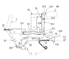
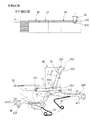
図5に、本発明の実施例である変色装置の構造を示す。それは、制御器20、糸提供部位、及び駆動部位により構成され、制御器20は、円形針織機の針織部に沿って運行している選択器30によって押し動かされる。電子装置である選択器30の数個の可動部品31(この機能はカムに等しい)は、通常、無効位置にあるが、制御回路またはメインコンピューターによって選択器30が制御器20近くに移動、接触位置に到達した可動部品31により、相対する制御器20上のトリガー(triggers)21が連動、トリガー(triggers)21は起動位置(enable position)に達する。
FIG. 5 shows the structure of a color changing apparatus that is an embodiment of the present invention. It is composed of a
制御器20は、トリガー(triggers)21及び第一安全テコ22、第二安全テコ23を含む。第一安全テコ22と第二安全テコ23の一端は、第一枢軸221において側板(plate)24に取り付けられている。トリガー(triggers)21の両端は、それぞれ第一端210と第二端211であるが、トリガー(triggers)21は鈎状位置回復部を突設する第一端210と第二端211間に位置する第二枢軸213によって側板(plate)24に取り付けられ、またトリガー(triggers)21の一側面には第二鈎部214を突設する。通常、トリガー(triggers)21、第一安全テコ22及び第二安全テコ23は全て閉鎖位置にあり(図7、8参照)、この時第一安全テコ22及び第二安全テコ23は、トリガー(triggers)21の第二端211により押圧された状態である。トリガー(triggers)21は第一端210が外力を受けると第二枢軸213を軸として起動位置に偏移、トリガー(triggers)21の第二端211が第一安全テコ22及び第二安全テコ23上部の凹部220凹部230まで滑移すると、第一安全テコ22及び第二安全テコ23は第一枢軸221を軸としてロック解除位置まで上方に動く。制御器20全体は、複数のトリガー(triggers)21及び第一安全テコ22第二安全テコ23によって組み合わされており、且つ、これらの部位はそれぞれ並列、制御器20全体を構成している。通常、同一部位中におけるトリガー(triggers)21に相対する第一安全テコ22の位置は図7に示すとおりであり、また、トリガー(triggers)21に相対する第二安全テコ23位置は図8に示すとおりである。
The
円形針織機の縁に固着する糸供給部位は、二つの部分により構成され、糸交換板40第一連結棒41第二連結棒42を含む第一部分は、糸Yを捉糸位置まで送ることを機能とし、可動刀板50、駆動連結棒51を含む第二部分は、指令待ち状態の下、糸Yの末端を挟み込み、糸交換時に切断することにより織物から離し元の指令待ち状態に戻すことを機能とする。また、前記の制御器20はこの糸供給部位の上方に固着する。第一部分と第二部分の二つの実施例を以下に説明する。
The yarn supply portion fixed to the edge of the circular needle loom is composed of two parts, and the first part including the
第一部分の糸交換板40、第一連結棒41、第二連結棒42は先端後端を連結した三連結棒構造であり、幾本かの異色の糸Yはそれぞれ異なる導糸環25を経て、糸交換板40先端の穿孔401に通される。通常において、そり状板である第一連結棒41の後端と第二連結棒42の先端は嵌合されており、第一連結棒41の中程にある突起部412と第一安全テコ22の底部は常に接触状態を保持、また第一連結棒41の先端両側面には上向きの前方突出部410及び下向きの後方突出部411を突設する。第二連結棒42の後端と糸交換板40の後端も嵌合されている。第二連結棒42は第一連結棒41の牽引力を糸交換板40に伝えることを機能とし、並びに第一連結棒41の牽引方向が変わると、連動される糸交換板40も通常の不作動位置(normal position)(図7参照)と外部に突伸した作動位置(external position)(図11参照)の間を前後移動する。第一部分は、他に、第一弾力部品43、第二弾力部品44を含んでおり、第一弾力部品43の一端は側板(plate)24に固定、もう一端は第一連結棒41の先端下方位置で第一連結棒41を支えている。これにより、トリガー(triggers)21が起動位置に偏移(図9参照)した場合、第一弾力部品43の上向きに押し上げる力によって第一連結棒41の先端もまた上方に押し上げられ、同時に第一安全テコ22がロック解除位置に移動することで、第一連結棒41の前方突出部410が側板(plate)24から突出、まもなく押し出される指令待ち状態となる。また、第二弾力部品44の機能も第一弾力部品43と同様、第一弾力部品43を補助し糸提供部位に必要な弾力を与える。
The first part of the
第二部分の可動刀板50後端と駆動連結棒51後端は嵌合され、駆動連結棒51の中程上方に突設した突起部512は、第二安全テコ23底部と常に接触状態を保持、また、駆動連結棒51先端両側それぞれに、上向きの前方突出部510と下向きの後方突出部511を突設し、50の通常挟糸位置(holding position)(図8参照)と、外部に突伸した放糸位置(release position)(図12参照)間の前後運動を連動する。第二部分はまた第三弾力部品52を含み、第三弾力部品52の一端は側板(plate)24に固着、もう一端は駆動連結棒51下方の先端に近い箇所において駆動連結棒51を支えている為、トリガー(triggers)21が起動位置に偏移した場合(図10参照)、第三弾力部品52の上方に押し上げる力により駆動連結棒51の先端を上に持ち上げ、同時に第二安全テコ23がロック解除位置に移ることで駆動連結棒51の前方突出部510が側板(plate)24から突出、まもなく押し出される指令待ち状態となる。
The rear end of the
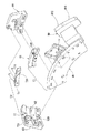
駆動部位は、第一組カム60第二組カム70位置回復カム80を含み、これらと選択器30は共に取付板90に取り付けられ(図6参照)、並びに選択器30と同時に、円形針織機の針織部に沿って運行する。第一組カム60と第二組カム70は、それぞれ前方カム61、前方カム71と後方カム62、後方カム72を含み、第一組カム60中の前方カム61は糸交換板40を外部の作動位置に押し出す働きを、また第二組カム70の前方カム71は可動刀板50を外部の放糸位置に押し出す働きを持つ。第一組カム60の後方カム62は糸交換板40を通常の不作動位置に戻し、第二組カム70の後方カム72は可動刀板50を通常の挟糸位置に戻す。挟糸位置にある時、可動刀板50先端の鈎部502は糸Yの後端を鈎部502と側板(plate)24間に挟み込む。
The driving portion includes a
図9〜図16を用いて、実際の作動方式を以下に説明する。 The actual operation method will be described below with reference to FIGS.
図9に示すとおり、選択器30の可動部品31は制御回路またはメインコンピューターによりコントロールされ、接触位置に移動、並びに選択器30は制御器20近くを通過、接触位置に到達した可動部品31が相対するトリガー(triggers)21の第二鈎部214を作動させ、各トリガー(triggers)21の第二鈎部214の高さが異なる為、選択器30中の異なる可動部品31が相対するトリガー(triggers)21の第二鈎部214に接触、それを作動させた後、トリガー(triggers)21は起動位置(enable position)まで移動する。この時、第一安全テコ22がロック解除位置に移ることで、第一連結棒41の前方突出部410は側板(plate)24から突出、まもなく押し出される指令待ち位置に達する。同時に、駆動連結棒51の前方突出部510もまた側板(plate)24から突出し、同じく、まもなく押し出される指令待ち位置に達する(図10参照)。
As shown in FIG. 9, the
続いて、駆動部位は糸供給部位に移動、この時第一組カム60の前方カム61の第一斜面610は、第一連結棒41の前方突出部410と接触して第一連結棒41と第二連結棒42を連動、糸交換板40を外部の作動位置に押し出す(図11参照)。また、第二組カム70中の前方カム71の第一斜面710もまた駆動連結棒51の前方突出部510に接触して、駆動連結棒51を連動する為、可動刀板50は外部の放糸位置に押し出される(図12参照)。
Subsequently, the drive portion moves to the yarn supply portion. At this time, the
位置回復カム80が再び制御器20に移動する際、位置回復カム80の前段斜面801はトリガー(triggers)21の鈎状位置回復部に徐々に近づき、位置回復カム80の後段平面802がトリガー(triggers)21を通常のロック位置に押し戻すことにより、第一連結棒41の後方突出部411は側板(plate)24の下方に露出する(図13参照)。これと同時に駆動連結棒51の後方突出部511もまた側板(plate)24の下方に露出する(図14参照)。
When the
最後に駆動部位が再び糸供給部位に移動すると、第一組カム60中の後方カム62の第一斜面620が第一連結棒41の後方突出部411に接触、第一連結棒41と第二連結棒42が連動されることにより、糸交換板40を通常の不作動位置に引き戻す(図15参照)。第二組カム70中の後方カム72の第一斜面720も駆動連結棒51の後方突出部511に接触、駆動連結棒51を連動することにより、更に可動刀板50を通常の挟糸位置に引き戻す(図16参照)。この時可動刀板50先端の鈎部502は、糸Yの後端を鈎部502と側板(plate)24の間に挟みこむのと同時に糸Yを切断する。
Finally, when the drive portion moves again to the yarn supply portion, the first
第一組カム60中の後方カム62と第二組カム70中の後方カム72の相互の作動時間差(即ち第一斜面620の後方突出部411への接触と、第一斜面720の後方突出部511への接触の時間差)は、需要に応じて調節可能である。可能な方法としては、後方カム62及び後方カム72を調節し、それぞれをカム座63、64上の位置に取り付ける。この種の設計では、変色(糸交換)時、旧糸を素早く元に戻して切断、新糸は引っ張られて切断されてしまう前に、その後端を可動刀板箇所より放すことで、糸が引っ張られて切断させるのを防ぐことができる為、糸の切れ端の発生を避けられ、織物の編織品質を更に向上させることができる。
The operating time difference between the
図6に、第二組カム70中前方カム71の二段式カムの実施例を示す。これは、固定カム73可動式カム74を含み、固定カム73の先端に第一斜面710を、可動式カム74には第二斜面730を設け、この固定カム73と可動式カム74は異なる高さに位置する。可動式カム74は、ボルト741で前方カム71に固定され、ボルト741を緩めると(図18参照)、固定カム73に相対する可動式カム74の位置を調節可能である。前期糸供給部位のいくつかの駆動連結棒51の後方突出部511もまた、高低の異なる前方突出部510と510aの2種に分かれ、この前方突出部510は固定カム73の第一斜面710によって押し動かされ前方突出部510aは可動式カム74の第二斜面730によって押し動かされる。
FIG. 6 shows an embodiment of a two-stage cam of the
図17に、六色変色装置の例を示す。かりに旧糸を第六号糸6、新糸を第一号糸1とし、織針が図中に示す捉糸点まで移動した場合、旧糸が遅すぎて可動刀板50によって放されるのを防ぐ為、可動式カム74の位置を前方に移動、第二斜面730と後方突出部511の時間を図18中のt1からt2に早めることも可能である。これにより、旧糸放出時間を変更、第六号糸6が引っ張られて切断させるのを防ぐことができる。
FIG. 17 shows an example of a six-color change device. If the old yarn is the sixth yarn 6 and the new yarn is the
10 糸交換板
101 後端
102 突出部
11 可動刀板
111 第一止め金
110 鈎部
112 第二止め金
12 本体
120 前縁
13 織針(needle)
Y 糸
Y1 糸末端
1 第一号糸
6 第六号糸
20 制御器
21 トリガー
210 第一端
211 第二端
212 鈎状位置回復部
213 第二枢軸
214 第二鈎部
22 第一安全テコ
221 第一枢軸
220、230 凹部
23 第二安全テコ
24 側板(plate)
25 導糸環
30 選択器
31 可動部品
40 糸交換板
401 穿孔
41 第一連結棒
410、510、510a 前方突出部
411、511 後方突出部
412、512 突起部
42 第二連結棒
43 第一弾力部品
44 第二弾力部品
50 可動刀板
51 駆動連結棒
52 第三弾力部品
60 第一組カム
61、71 前方カム
62、72 後方カム
610 第一斜面
620 第二斜面
63、64 カム座
70 第二組カム
73 固定カム
74 可動式カム
741 ボルト
710、720 第一斜面
730 第二斜面
80 位置回復カム
801 前段斜面
802 後段平面
90 取付板
DESCRIPTION OF
Y thread
25
Claims (5)
(a)制御器は、円形針織機の針織部に沿って運行する選択器により連動され、
(b)糸供給部位は、二つの部分により構成され、糸交換板、第一連結棒及び第二連結棒を含む第一部分は、糸Yを捉糸位置まで送り、可動刀板、駆動連結棒を含む第二部分は、指令待ち状態の下、糸の末端を挟み込み、また、糸交換時に旧糸を切断することにより織物から離し元の指令待ち状態に戻し、
(c)駆動部位は、選択器と同時に円形針織機の針織部に沿って運行し、第一組カム第二組カムによって構成され、糸交換板と可動刀板はそれぞれ第一組カと第二組カムにより連動され、第一組カムと第二組カムは、前方カム(forward cam)と後方カム(backward cam)を含み、第一組カム中の前方カムは糸交換板を外部の作動位置(external position)に押し出す働きを、第二組カム中の前方カムは可動刀板を外部の放糸位置(release positon)に押し出す働きを持ち、また、第一組カム中の後方カムは糸交換板を通常の不作動位置(normal positon)に戻し、第二組カムの後方カムは可動刀板を通常の挟糸位置(holding position)に戻すことを特徴とする円形針織機の変色装置。 The color changing device of the circular needle loom includes the following components (a), (b), and (c):
(A) The controller is linked by a selector operating along the needle weaving part of the circular needle loom,
(B) The yarn supply part is composed of two parts, and the first part including the yarn exchange plate, the first connecting rod and the second connecting rod feeds the yarn Y to the catching position, and the movable blade plate and the drive connecting rod. The second part including the pinch the end of the yarn under the command waiting state, and by cutting the old yarn at the time of yarn replacement, it is separated from the fabric and returned to the original command waiting state,
(C) The driving part operates along the needle weaving portion of the circular needle loom simultaneously with the selector, and is constituted by the first set cam and the second set cam, and the thread change plate and the movable blade plate are the first set and the first set respectively. Interlocked by two sets of cams, the first set cam and the second set cam include a forward cam and a backward cam, and the front cam in the first set cam operates the thread change plate externally. The front cam in the second set cam has the function of pushing out the movable blade to the external release position, and the rear cam in the first set cam has the function of pushing out to the position (external position). The replacement plate is returned to the normal normal position, and the rear cam of the second set of cams returns the movable blade plate to the normal holding position. Discoloration device circular needle loom to.
5. The discoloration device for a circular needle loom according to claim 4, wherein the movable cam is fixed to the front cam with a bolt, and the position of the movable cam relative to the fixed cam can be adjusted by loosening the bolt.
Priority Applications (1)
| Application Number | Priority Date | Filing Date | Title |
|---|---|---|---|
| JP2005345930A JP4122025B2 (en) | 2005-11-30 | 2005-11-30 | Discoloring device for circular knitting machine |
Applications Claiming Priority (1)
| Application Number | Priority Date | Filing Date | Title |
|---|---|---|---|
| JP2005345930A JP4122025B2 (en) | 2005-11-30 | 2005-11-30 | Discoloring device for circular knitting machine |
Publications (2)
| Publication Number | Publication Date |
|---|---|
| JP2007146346A true JP2007146346A (en) | 2007-06-14 |
| JP4122025B2 JP4122025B2 (en) | 2008-07-23 |
Family
ID=38208082
Family Applications (1)
| Application Number | Title | Priority Date | Filing Date |
|---|---|---|---|
| JP2005345930A Expired - Fee Related JP4122025B2 (en) | 2005-11-30 | 2005-11-30 | Discoloring device for circular knitting machine |
Country Status (1)
| Country | Link |
|---|---|
| JP (1) | JP4122025B2 (en) |
Cited By (5)
| Publication number | Priority date | Publication date | Assignee | Title |
|---|---|---|---|---|
| JP2010156093A (en) * | 2008-12-29 | 2010-07-15 | Hakuryu Kikaisho Kofun Yugenkoshi | Feed yarn changing device for feed yarn altering head |
| CN101906698A (en) * | 2010-08-19 | 2010-12-08 | 吴宇芯 | Yarn clamping and cutting method and device thereof |
| KR101085294B1 (en) | 2010-04-20 | 2011-11-22 | 파이룽 머시너리 밀 코., 엘티디. | Circular knitting machine having integrated multiple yarn changing apparatus |
| KR102020613B1 (en) * | 2018-06-11 | 2019-09-11 | 이백용 | Cutting adjuster for sock knitting machine |
| CN110644127A (en) * | 2019-10-22 | 2020-01-03 | 泉州全能智控机械研究所有限公司 | Wire adjusting head |
-
2005
- 2005-11-30 JP JP2005345930A patent/JP4122025B2/en not_active Expired - Fee Related
Cited By (6)
| Publication number | Priority date | Publication date | Assignee | Title |
|---|---|---|---|---|
| JP2010156093A (en) * | 2008-12-29 | 2010-07-15 | Hakuryu Kikaisho Kofun Yugenkoshi | Feed yarn changing device for feed yarn altering head |
| KR101085294B1 (en) | 2010-04-20 | 2011-11-22 | 파이룽 머시너리 밀 코., 엘티디. | Circular knitting machine having integrated multiple yarn changing apparatus |
| CN101906698A (en) * | 2010-08-19 | 2010-12-08 | 吴宇芯 | Yarn clamping and cutting method and device thereof |
| KR102020613B1 (en) * | 2018-06-11 | 2019-09-11 | 이백용 | Cutting adjuster for sock knitting machine |
| CN110644127A (en) * | 2019-10-22 | 2020-01-03 | 泉州全能智控机械研究所有限公司 | Wire adjusting head |
| CN110644127B (en) * | 2019-10-22 | 2024-03-15 | 泉州全能智控机械研究所有限公司 | Wire adjusting head |
Also Published As
| Publication number | Publication date |
|---|---|
| JP4122025B2 (en) | 2008-07-23 |
Similar Documents
| Publication | Publication Date | Title |
|---|---|---|
| US7036343B1 (en) | Striping apparatus of a circular knitting machine | |
| JP3545750B2 (en) | Color change device for circular knitting machine | |
| US6988385B2 (en) | Yarn feeder of weft knitting machine and method of feeding yarn for weft knitting machine | |
| JP2007146346A (en) | Color-changing device of circular needle loom | |
| CN101018901B (en) | Yarn feeder of yarn feeding device in weft knitting machine | |
| JP5330249B2 (en) | Flat knitting machine | |
| JP2702100B2 (en) | Method for producing patterned knitted fabric and warp knitting machine | |
| JP2005042260A (en) | Feed yarn changeover apparatus for circular knitting machine and changeover method | |
| TWI444514B (en) | Striped tissue braiding device and weaving method for yarn feeder of circular knitting machine | |
| EP3608461A1 (en) | Plating knitting method used in flat knitting machine | |
| JP3540448B2 (en) | Knitting tool controller in circular knitting machine | |
| JP4201342B2 (en) | Discoloration head of high-speed single-sided circular knitting machine | |
| JP4015973B2 (en) | Knitting yarn holding and cutting method and apparatus | |
| CN100547138C (en) | The color-changing device of circular knitter | |
| EP1783256B1 (en) | A striping apparatus of a circular knitting machine | |
| TWI546433B (en) | Method and knitting machine for the production of knitted goods with horizontal stripe patterns | |
| JP2008297662A (en) | Yarn feed-switching device in circular knitting machine | |
| JP2009531557A (en) | Circular knitting machine for socks etc. | |
| JPH07197358A (en) | Jacquard guide and jacquard guide unit | |
| CN100526530C (en) | Yarn feed switching device for circular loom | |
| JP5757830B2 (en) | Flat knitting machine provided with compound needle, and slider control method of flat knitting machine | |
| JP2004131908A (en) | Yarn-feeding device in knitting machine | |
| CN1289732C (en) | Color bleeding apparatus of tubular knitting machine | |
| TWI534316B (en) | Multi - purpose round knitting towel knitting machine | |
| JP2004204360A (en) | Feed yarn changeover apparatus in circular knitting machine |
Legal Events
| Date | Code | Title | Description |
|---|---|---|---|
| A131 | Notification of reasons for refusal |
Free format text: JAPANESE INTERMEDIATE CODE: A131 Effective date: 20070807 |
|
| A601 | Written request for extension of time |
Free format text: JAPANESE INTERMEDIATE CODE: A601 Effective date: 20071106 |
|
| A602 | Written permission of extension of time |
Free format text: JAPANESE INTERMEDIATE CODE: A602 Effective date: 20071109 |
|
| A521 | Written amendment |
Free format text: JAPANESE INTERMEDIATE CODE: A523 Effective date: 20071205 |
|
| TRDD | Decision of grant or rejection written | ||
| A01 | Written decision to grant a patent or to grant a registration (utility model) |
Effective date: 20080401 Free format text: JAPANESE INTERMEDIATE CODE: A01 |
|
| A61 | First payment of annual fees (during grant procedure) |
Free format text: JAPANESE INTERMEDIATE CODE: A61 Effective date: 20080430 |
|
| FPAY | Renewal fee payment (prs date is renewal date of database) |
Year of fee payment: 3 Free format text: PAYMENT UNTIL: 20110509 |
|
| R150 | Certificate of patent (=grant) or registration of utility model |
Free format text: JAPANESE INTERMEDIATE CODE: R150 |
|
| FPAY | Renewal fee payment (prs date is renewal date of database) |
Free format text: PAYMENT UNTIL: 20120509 Year of fee payment: 4 |
|
| FPAY | Renewal fee payment (prs date is renewal date of database) |
Free format text: PAYMENT UNTIL: 20130509 Year of fee payment: 5 |
|
| LAPS | Cancellation because of no payment of annual fees |