JP2007145017A - Multi-engine system with media pass through mode - Google Patents
Multi-engine system with media pass through mode Download PDFInfo
- Publication number
- JP2007145017A JP2007145017A JP2006312344A JP2006312344A JP2007145017A JP 2007145017 A JP2007145017 A JP 2007145017A JP 2006312344 A JP2006312344 A JP 2006312344A JP 2006312344 A JP2006312344 A JP 2006312344A JP 2007145017 A JP2007145017 A JP 2007145017A
- Authority
- JP
- Japan
- Prior art keywords
- imes
- medium
- mode
- ime
- marking
- Prior art date
- Legal status (The legal status is an assumption and is not a legal conclusion. Google has not performed a legal analysis and makes no representation as to the accuracy of the status listed.)
- Pending
Links
Images
Classifications
-
- H—ELECTRICITY
- H04—ELECTRIC COMMUNICATION TECHNIQUE
- H04N—PICTORIAL COMMUNICATION, e.g. TELEVISION
- H04N1/00—Scanning, transmission or reproduction of documents or the like, e.g. facsimile transmission; Details thereof
- H04N1/32—Circuits or arrangements for control or supervision between transmitter and receiver or between image input and image output device, e.g. between a still-image camera and its memory or between a still-image camera and a printer device
- H04N1/32502—Circuits or arrangements for control or supervision between transmitter and receiver or between image input and image output device, e.g. between a still-image camera and its memory or between a still-image camera and a printer device in systems having a plurality of input or output devices
- H04N1/32523—Circuits or arrangements for control or supervision between transmitter and receiver or between image input and image output device, e.g. between a still-image camera and its memory or between a still-image camera and a printer device in systems having a plurality of input or output devices a plurality of output devices
-
- G—PHYSICS
- G03—PHOTOGRAPHY; CINEMATOGRAPHY; ANALOGOUS TECHNIQUES USING WAVES OTHER THAN OPTICAL WAVES; ELECTROGRAPHY; HOLOGRAPHY
- G03G—ELECTROGRAPHY; ELECTROPHOTOGRAPHY; MAGNETOGRAPHY
- G03G15/00—Apparatus for electrographic processes using a charge pattern
- G03G15/55—Self-diagnostics; Malfunction or lifetime display
-
- H—ELECTRICITY
- H04—ELECTRIC COMMUNICATION TECHNIQUE
- H04N—PICTORIAL COMMUNICATION, e.g. TELEVISION
- H04N1/00—Scanning, transmission or reproduction of documents or the like, e.g. facsimile transmission; Details thereof
- H04N1/32—Circuits or arrangements for control or supervision between transmitter and receiver or between image input and image output device, e.g. between a still-image camera and its memory or between a still-image camera and a printer device
- H04N1/32502—Circuits or arrangements for control or supervision between transmitter and receiver or between image input and image output device, e.g. between a still-image camera and its memory or between a still-image camera and a printer device in systems having a plurality of input or output devices
- H04N1/32523—Circuits or arrangements for control or supervision between transmitter and receiver or between image input and image output device, e.g. between a still-image camera and its memory or between a still-image camera and a printer device in systems having a plurality of input or output devices a plurality of output devices
- H04N1/32539—Detecting or indicating the status of the output devices
-
- H—ELECTRICITY
- H04—ELECTRIC COMMUNICATION TECHNIQUE
- H04N—PICTORIAL COMMUNICATION, e.g. TELEVISION
- H04N1/00—Scanning, transmission or reproduction of documents or the like, e.g. facsimile transmission; Details thereof
- H04N1/32—Circuits or arrangements for control or supervision between transmitter and receiver or between image input and image output device, e.g. between a still-image camera and its memory or between a still-image camera and a printer device
- H04N1/32502—Circuits or arrangements for control or supervision between transmitter and receiver or between image input and image output device, e.g. between a still-image camera and its memory or between a still-image camera and a printer device in systems having a plurality of input or output devices
- H04N1/32545—Distributing a job or task among a plurality of input devices or a plurality of output devices
-
- H—ELECTRICITY
- H04—ELECTRIC COMMUNICATION TECHNIQUE
- H04N—PICTORIAL COMMUNICATION, e.g. TELEVISION
- H04N1/00—Scanning, transmission or reproduction of documents or the like, e.g. facsimile transmission; Details thereof
- H04N1/32—Circuits or arrangements for control or supervision between transmitter and receiver or between image input and image output device, e.g. between a still-image camera and its memory or between a still-image camera and a printer device
- H04N1/32609—Fault detection or counter-measures, e.g. original mis-positioned, shortage of paper
- H04N1/32614—Fault detection or counter-measures, e.g. original mis-positioned, shortage of paper related to a single-mode communication, e.g. at the transmitter or at the receiver
-
- H—ELECTRICITY
- H04—ELECTRIC COMMUNICATION TECHNIQUE
- H04N—PICTORIAL COMMUNICATION, e.g. TELEVISION
- H04N1/00—Scanning, transmission or reproduction of documents or the like, e.g. facsimile transmission; Details thereof
- H04N1/32—Circuits or arrangements for control or supervision between transmitter and receiver or between image input and image output device, e.g. between a still-image camera and its memory or between a still-image camera and a printer device
- H04N1/32609—Fault detection or counter-measures, e.g. original mis-positioned, shortage of paper
- H04N1/32625—Fault detection
- H04N1/32635—Fault detection of reproducing apparatus or receiver, e.g. out of paper
-
- H—ELECTRICITY
- H04—ELECTRIC COMMUNICATION TECHNIQUE
- H04N—PICTORIAL COMMUNICATION, e.g. TELEVISION
- H04N1/00—Scanning, transmission or reproduction of documents or the like, e.g. facsimile transmission; Details thereof
- H04N1/32—Circuits or arrangements for control or supervision between transmitter and receiver or between image input and image output device, e.g. between a still-image camera and its memory or between a still-image camera and a printer device
- H04N1/32609—Fault detection or counter-measures, e.g. original mis-positioned, shortage of paper
- H04N1/32646—Counter-measures
- H04N1/32673—Adjusting or controlling an operating mode, e.g. from paper reception to memory reception
-
- G—PHYSICS
- G03—PHOTOGRAPHY; CINEMATOGRAPHY; ANALOGOUS TECHNIQUES USING WAVES OTHER THAN OPTICAL WAVES; ELECTROGRAPHY; HOLOGRAPHY
- G03G—ELECTROGRAPHY; ELECTROPHOTOGRAPHY; MAGNETOGRAPHY
- G03G2215/00—Apparatus for electrophotographic processes
- G03G2215/00016—Special arrangement of entire apparatus
- G03G2215/00021—Plural substantially independent image forming units in cooperation, e.g. for duplex, colour or high-speed simplex
Abstract
Description
本発明は、画像マーキングエンジン、マーキングエンジン、IME(Image Marking Engine)等と称される画像記録装置を複数個備えたシステム即ちマルチエンジンシステムに関し、例えば印刷用マルチエンジンシステムにおける機能性や機能拡張性の向上に関する。中でも、本発明を適用できるマルチエンジンシステムの代表例は、その印刷能力乃至印刷機能に異同がある何個かのマーキングエンジンから構成された印刷モジュールを複数個統合或いは直列配置したシステムである。そこで、以下の説明においてはそうしたシステムを念頭におくこととするが、本発明を他種用途向けに変形実施することも可能であることを理解されたい。 The present invention relates to a system including a plurality of image recording apparatuses called an image marking engine, a marking engine, and IME (Image Marking Engine), that is, a multi-engine system. Related to improvement. Among them, a representative example of a multi-engine system to which the present invention can be applied is a system in which a plurality of printing modules each composed of several marking engines having different printing capabilities or printing functions are integrated or arranged in series. Thus, in the following description, such a system will be considered, but it should be understood that the present invention can be modified for other types of applications.
媒体シート上に画像をマーキング即ち記録する装置としては、今日までに多くの種類が実用化されている。例えば、感光媒体等を介し原稿画像を媒体シート上に複写記録する複写機もあり、電子信号に形態変換された画像情報を媒体シート上に画像として再現するプリンタもある。後者には、更に、印刷方式としてインパクト方式を採るものと非インパクト方式を採るものとがある。インパクト方式は例えばタイプライタやワイヤドットプリンタにて採用されており、非インパクト方式は例えば感熱プリンタやインクジェットプリンタやレーザビームプリンタにて採用されている。 Many types of devices for marking or recording images on media sheets have been put to practical use to date. For example, there is a copying machine that copies and records a document image on a medium sheet via a photosensitive medium or the like, and there is a printer that reproduces image information converted into an electronic signal as an image on a medium sheet. The latter further includes an impact method as a printing method and a non-impact method. The impact method is adopted in, for example, a typewriter or a wire dot printer, and the non-impact method is adopted in, for example, a thermal printer, an ink jet printer, or a laser beam printer.
中でも電子写真印刷装置は、電子的に画像を複製する印刷システム用のマーキングエンジンとして広く採用されており、基本的に次のような仕組みで機能する。即ち、まずその電位が実質的に均一になるよう、光導電部材例えば光導電ベルトの一部表面に帯電させる(均一帯電)。すると、光導電部材の表面(光導電面)のうち帯電された部分が感光可能状態になる。次いで、この光導電面上の帯電部分を部位選択的に輻射光に露出させる(露光)。すると、露光部分から電荷が散逸するため、光導電面上には、電荷が散逸した露光部分又はそれと相補的な非露光部分による静電潜像が形成される。従って、複製対象原稿中の情報エリアに相応するパターンにて輻射光を照らすことで、情報エリアの複製に相当する静電潜像を形成することができる(画像状帯電)。静電潜像形成後はそれを光導電面から媒体シートに転写して永久的に固着させる。例えば、光導電面上の静電潜像にトナーを付着させることによりトナー像を形成し(現像)、形成されたトナー像を光導電面から媒体シート上に写し取り(転写)、転写されたトナー像を加熱して媒体シートに永久固着させる(融着)。これにより、媒体シート上に原稿画像が複製される。 In particular, the electrophotographic printing apparatus is widely used as a marking engine for a printing system that electronically replicates an image, and basically functions in the following manner. That is, first, a part of the surface of a photoconductive member, for example, a photoconductive belt, is charged (uniform charging) so that the potential becomes substantially uniform. As a result, the charged portion of the surface (photoconductive surface) of the photoconductive member is in a photosensitive state. Next, the charged portion on the photoconductive surface is selectively exposed to radiation light (exposure). Then, since the charge is dissipated from the exposed portion, an electrostatic latent image is formed on the photoconductive surface by the exposed portion where the charge is dissipated or a non-exposed portion complementary thereto. Therefore, an electrostatic latent image corresponding to duplication of the information area can be formed by irradiating the radiation light with a pattern corresponding to the information area in the original to be duplicated (image-like charging). After forming the electrostatic latent image, it is transferred from the photoconductive surface to the medium sheet and permanently fixed. For example, a toner image is formed (development) by attaching toner to an electrostatic latent image on the photoconductive surface, and the formed toner image is copied (transferred) from the photoconductive surface onto a medium sheet and transferred. The toner image is heated and permanently fixed to the medium sheet (fusion). As a result, the original image is duplicated on the medium sheet.
以上説明したプロセスは白黒電子写真印刷プロセスであるが、多色電子写真印刷プロセスも本質的には同じプロセスである。但し、白黒印刷時に光導電面上に記録、形成される静電潜像が1個であるのと違い、多色印刷時にはそれぞれ別の色に対応する複数個の静電潜像(単色潜像)が順を追って記録、形成され、各単色潜像がその単色潜像に係る色に対し相補的な色のトナーにより現像される。例えば、ある色に係る単色潜像を形成してその色に対し相補的な色のトナーによりその単色潜像を現像する、という処理を、単色潜像毎にトナー色を変えつつ繰り返して実行することにより、それら複数個の単色潜像が現像される。更に、こうして形成した各色トナー像を、各色トナー像が媒体シート上でぴったりと重なり合うよう位置を合わせつつ、媒体シート上に転写する。こうして媒体シート上に形成した多層トナー像をその媒体シート上に永久固着させれば、媒体シート上に多色画像ができあがる。なお、現像素材としては液状のものも粉体状のものも使用できる。 The process described above is a black and white electrophotographic printing process, but a multicolor electrophotographic printing process is essentially the same process. However, unlike a single electrostatic latent image recorded and formed on the photoconductive surface during monochrome printing, a plurality of electrostatic latent images (single color latent images) corresponding to different colors are used during multicolor printing. ) Are sequentially recorded and formed, and each single-color latent image is developed with toner of a color complementary to the color related to the single-color latent image. For example, a process of forming a single-color latent image for a certain color and developing the single-color latent image with toner of a color complementary to that color is repeatedly executed while changing the toner color for each single-color latent image. Thus, the plurality of single-color latent images are developed. Further, each color toner image formed in this way is transferred onto the medium sheet while aligning the positions so that the color toner images exactly overlap on the medium sheet. If the multilayer toner image thus formed on the medium sheet is permanently fixed on the medium sheet, a multicolor image is formed on the medium sheet. The developing material can be either liquid or powdery.
白黒電子写真印刷プロセスにおいては、媒体シート例えばコピー用紙を装置入口例えば給紙トレイから電子写真印刷装置内に送り込み、次いで電子写真印刷装置内に設けられている所定の経路に沿って先送りしつつその経路沿いで媒体シート上にトナー像を転写及び永久固着させ、そしてその媒体シートを装置出口例えば排紙トレイから装置外に送り出して装置オペレータに引き渡す。多色電子写真印刷プロセスでも、白黒電子写真印刷プロセスと同じく装置入口から電子写真印刷装置内に媒体シートを送り込み装置出口から媒体シートを装置外に送り出して装置オペレータに引き渡すのであるが、白黒電子写真印刷プロセスと違い電子写真印刷装置内で媒体シート上に複数個のトナー像を転写、永久固着させる。そのため、例えば、電子写真印刷装置から出てくる媒体シートの縁を捉えるシートグリッパをシートトランスポートに取り付け、このシートグリッパによって捉えた媒体シートを再循環経路内に送り込めるようにする。再循環経路に送り込まれた媒体シートは電子写真印刷装置内に再び通され、その上に再び(別の色の)トナー像が記録、形成される(マルチパス印刷)。その際、シートグリッパから再循環経路内への媒体シートの送り込みを適宜制御することにより、各色トナー像の相互位置を正確に合わせることができる。即ち、例えばマゼンタ、シアン、イエロー及びブラックの各色トナー像が媒体シート上で正確に重なるよう位置合わせして転写することができる。 In the black and white electrophotographic printing process, a media sheet such as a copy sheet is fed into the electrophotographic printing apparatus from the apparatus entrance, for example, a paper feed tray, and then advanced along a predetermined path provided in the electrophotographic printing apparatus. The toner image is transferred and permanently fixed on the medium sheet along the path, and the medium sheet is sent out of the apparatus from an apparatus outlet, for example, a paper discharge tray, and delivered to the apparatus operator. In the multicolor electrophotographic printing process, the medium sheet is fed into the electrophotographic printing apparatus from the apparatus entrance and sent out of the apparatus from the apparatus outlet and delivered to the apparatus operator as in the black and white electrophotographic printing process. Unlike the printing process, a plurality of toner images are transferred and permanently fixed on a medium sheet in an electrophotographic printing apparatus. Therefore, for example, a sheet gripper that captures the edge of the media sheet coming out of the electrophotographic printing apparatus is attached to the sheet transport so that the media sheet captured by the sheet gripper can be fed into the recirculation path. The medium sheet sent to the recirculation path is again passed through the electrophotographic printing apparatus, and a toner image (of another color) is recorded and formed thereon again (multi-pass printing). At that time, by appropriately controlling the feeding of the medium sheet from the sheet gripper into the recirculation path, the mutual positions of the respective color toner images can be accurately adjusted. That is, for example, magenta, cyan, yellow, and black color toner images can be aligned and transferred so as to be accurately superimposed on the medium sheet.
また、電子写真印刷を含む各種画像記録方式にて、片面記録だけでなく両面記録も行える装置が常識化している。これは、媒体シート両面に画像を記録(複写、印刷等)することにより、媒体シート使用枚数を減らすことができ、ひいては資源や文書格納スペースを節約できるためである。また、両面記録方式としては、少なくとも次の二種類が実用化されている。第1の方式は、複数枚の媒体シートにまず片面だけをまとめて記録する方式である。この方式では、表の面の記録が済んだ媒体シートを一旦所定の蓄積場所に送り込み、当該蓄積場所に溜まった複数枚の片面記録済媒体シートをそこから取り出して裏面の記録を行う。この方式は、同一内容書面を複数枚一括作成するとき、即ちどの媒体シートの表面にも同じ内容の画像を記録しまたどの媒体シートの裏面にも同じ内容の画像を記録するときには効率的であるが、媒体シート毎にまたその面毎に違う内容の画像を記録したいときには効率性低下要因となり得る。例えば、最初の媒体シートの表面に第1頁、裏面に第2頁、その次の媒体シートの表面に第3頁、裏面に第4頁、というように、媒体シート毎にまた面毎に違う内容を記録したいとする。この場合に第1の方式を採ると、まず各媒体シートを順繰りに装置内に送り込んで奇数頁の画像を第1頁、第3頁、第5頁、…という順で記録し、奇数頁記録が済んだらそれら媒体シートを表面の頁の順に装置内に送り込んでその裏面に第2頁、第4頁、第6頁、…という順で偶数頁の画像を記録することとなる。こうした動作が所期通りに行われればよいが、実際には、裏面記録の際に、複数枚の媒体シートが一緒に装置内に送り込まれてしまうこともあろうし、また媒体シートが詰まることもあろう。そうした場合、両面記録が済んだ媒体シートの表面と裏面の頁関係が望み通りにならず、最初から両面記録作業・操作をやり直すことを余儀なくされる。これに対し、表面に表頁の画像を記録したら次いでその裏面にその裏頁の画像を記録する、という動作を媒体シート1枚単位で繰り返す第2の方式では、表面と裏面の頁関係がちぐはぐになるという問題は生じにくいが、媒体シート送給経路の切替が頻繁に行われるため媒体シート送給所要時間が長く、効率に欠けるきらいがある。また、これら第1及び第2の方式に共通する問題として、装置内媒体シート搬送経路が複雑であり、また媒体シート搬送経路上のどこかで媒体シートを表裏反転させねばならないため、媒体シート搬送動作に対する信頼性を向上させることがかなり難しいという問題がある。 In addition, apparatuses capable of performing not only single-sided recording but also double-sided recording by various image recording methods including electrophotographic printing have become common sense. This is because by recording (copying, printing, etc.) images on both sides of the media sheet, the number of media sheets used can be reduced, and as a result, resources and document storage space can be saved. Further, at least the following two types have been put to practical use as the double-sided recording method. The first method is a method in which only one side is first recorded on a plurality of medium sheets. In this method, the medium sheet on which the front surface has been recorded is once sent to a predetermined accumulation location, and a plurality of single-side recorded media sheets accumulated at the accumulation location are taken out from the medium sheet to record the back surface. This method is efficient when a plurality of identical content documents are created at once, that is, when an image with the same content is recorded on the front surface of any media sheet and an image with the same content is recorded on the back surface of any media sheet. However, when it is desired to record an image having a different content for each medium sheet and for each surface, it can be a factor for reducing efficiency. For example, the first page on the front surface of the first media sheet, the second page on the back surface, the third page on the front surface of the next media sheet, the fourth page on the back surface, etc. Suppose you want to record the contents. In this case, if the first method is adopted, first, the respective media sheets are sequentially fed into the apparatus to record the odd page images in the order of the first page, the third page, the fifth page,. Then, the media sheets are fed into the apparatus in the order of the front page, and the images of the even pages are recorded in the order of the second page, the fourth page, the sixth page,. It is sufficient if these operations are performed as expected. However, in actuality, a plurality of media sheets may be sent together into the apparatus during back side recording, or the media sheets may be jammed. I will. In such a case, the page relationship between the front surface and the back surface of the medium sheet on which double-sided recording has been completed is not as desired, and the double-sided recording operation / operation is forced to start from the beginning. On the other hand, in the second method in which the operation of recording the front page image on the front side and then recording the back page image on the back side is repeated for each medium sheet, the page relationship between the front side and the back side is inconsistent. However, since the media sheet feeding path is frequently switched, the time required for feeding the media sheet is long and the efficiency may be insufficient. Further, as a problem common to the first and second methods, the medium sheet conveyance path in the apparatus is complicated, and the medium sheet has to be turned upside down somewhere on the medium sheet conveyance path. There is a problem that it is quite difficult to improve the reliability of the operation.
また、同一媒体シートの同一面上に複数種類の情報を重畳記録したいという要請もある。とりわけ、近年においては様々な分野でカラーリングが進展しており、そうした分野では例えば同一媒体シートの同一面上に白黒印刷像と多色印刷像を混在させたいという要請が生まれている。白黒印刷像及び多色印刷像を同一媒体シート上に重畳記録、形成するには、例えば、まず媒体シート上への白黒印刷を行い、それを終えたら現像装置を白黒印刷用のものから多色印刷用のものへと交換し、そして同じ面上への多色印刷を行う、というやり方を採ればよい。このやり方には、単純且つ簡明というよいところもあるものの、時間と手間を食うという問題がある。 There is also a demand for superimposing and recording multiple types of information on the same surface of the same medium sheet. In particular, in recent years, coloring has progressed in various fields. In such fields, for example, a demand has arisen for mixing black and white print images and multicolor print images on the same surface of the same medium sheet. In order to record and form a black and white print image and a multicolor print image on the same medium sheet, for example, the black and white print is first performed on the medium sheet, and after that, the developing device is changed from the one for monochrome print to the multicolor print. You can replace it with one for printing and perform multicolor printing on the same surface. This approach has the advantage of being simple and concise, but takes time and effort.
更に、同一媒体シートの同一面上に複数種類の画像を重畳記録する場合、画像位置正確性にとりわけ注意すべきである。画像位置正確性が不十分な場合、同一面上に記録した複数種類の画像間での位置ずれや、その面上に予め記録されている不動画像例えばフレームに対する各画像の位置ずれが生じるため、媒体シート上の記録画像は看視に耐え得ないものになる。 Furthermore, when multiple types of images are superimposed and recorded on the same surface of the same medium sheet, special attention should be paid to the image position accuracy. If the image position accuracy is insufficient, position displacement between multiple types of images recorded on the same surface and immovable images prerecorded on the surface, for example, position displacement of each image with respect to the frame, The recorded image on the media sheet is unbearable for viewing.
そして、電子写真印刷等の画像記録方式には固有の高速化限界がある。昨今、画像記録装置に対する高速化要求、高生産性化要求は否応なしに高まってきており、これに応ずるため高速化限界を緩和、回避することを狙った試みが様々になされているが、これまでなされてきた試みの多くは、また別の大きな問題を招くか、でなければ装置構成の大型化及び嵩張りを招くものとなっている。画像記録装置例えば高速プリンタの中には大型化及び嵩張りを承知の上で商品化されているものもあるが、そうした画像記録装置は一般に高価格で不経済である。画像記録装置に対する高額出費を容認でき、またその種の画像記録装置に付きものの厄介さ、複雑な構成等を受忍できる者は、ごく一部の大量印刷顧客に限られている。 An image recording method such as electrophotographic printing has an inherent speed limit. Recently, the demand for higher speed and higher productivity for image recording devices has been inevitably increasing, and various attempts have been made to alleviate and avoid the speed limit to meet this demand. Many of the attempts made up to this point cause another big problem, or the size and the bulk of the apparatus are increased. Some image recording devices, such as high-speed printers, are commercialized with an awareness of their size and bulkiness, but such image recording devices are generally expensive and uneconomical. Only a few high-volume printing customers are able to accept the high cost of image recording devices and to accept the nuisances, complex configurations, etc. associated with such image recording devices.
高速化要請に対処でき比較的小型且つ簡素な構成で低コスト化も可能な構成としては、例えば、用紙源と仕上げステーションとの間に複数台のマーキングエンジンを連結した直列型乃至タンデム型の構成があるが、この構成にも問題がある。即ち、何れかのマーキングエンジンで不具合が生じた場合、サービスパーソンが到着するまでの間、不具合のないものも含め全てのマーキングエンジンを動作させることができないという問題がある。これは、利用時間、稼働時間の損逸である。 For example, a series or tandem configuration in which multiple marking engines are connected between a paper source and a finishing station as a configuration that can cope with a request for high speed and can be reduced in cost with a relatively small and simple configuration. There is a problem with this configuration as well. That is, when a problem occurs in any of the marking engines, there is a problem that not all marking engines, including those without a defect, can be operated until the service person arrives. This is a loss of usage time and operating time.
ここに、本発明の一実施形態に係る統合型の印刷システムは、直列配置された複数個のIMEと、それらIMEにおける所定種類不具合の発生を検知可能な制御システムと、を備え、その動作モードとして、少なくとも2個のIMEに媒体を通しそれらIMEを任意に使用してその媒体にマーキングする第1動作モードと、第1動作モードにて使用されたIMEそれぞれに媒体を通すがそのうち所定種類不具合の発生が検知されたIMEは単に通過させるだけにし残りのIMEを使用してその媒体にマーキングする第2動作モードと、を有する。本実施形態における制御システムは、IMEのうち1個にて所定種類不具合が発生したことを検知した場合に、当該不具合が発生したIMEが通過のみとされるよう第2動作モードにて本印刷システムを動作させる。 Here, an integrated printing system according to an embodiment of the present invention includes a plurality of IMEs arranged in series and a control system capable of detecting occurrence of a predetermined type of failure in the IMEs, and an operation mode thereof. The first operation mode in which a medium is passed through at least two IMEs and the IME is arbitrarily used to mark the medium, and the medium is passed through each of the IMEs used in the first operation mode. A second mode of operation in which the detected IME is simply passed and the remaining IME is used to mark the medium. When the control system in the present embodiment detects that a predetermined type of failure has occurred in one of the IMEs, the printing system in the second operation mode so that the IME in which the failure has occurred is only passed. To work.
また、本発明の他の実施形態に係る媒体印刷方法は、直列配置された複数個のIMEを有する統合型の印刷システムにて実行される。本実施形態においては、媒体送給源から少なくとも1個のIMEに媒体を送給して少なくとも2個のIMEに媒体を通し、媒体が通るIMEを任意に使用してその媒体にマーキングする第1動作モードから、第1動作モードで使用される各IMEに媒体を通すがそのうち少なくとも1個は単に通過させるだけにし残りのIMEを使用してその媒体にマーキングする第2動作モードへの、切替が実行される。 A medium printing method according to another embodiment of the present invention is executed by an integrated printing system having a plurality of IMEs arranged in series. In the present embodiment, the first operation of feeding a medium from a medium supply source to at least one IME, passing the medium through at least two IMEs, and optionally marking the medium using the IME through which the medium passes. Switch from mode to second mode of operation where media is passed through each IME used in the first mode of operation but at least one of them is simply passed through and the remaining IME is used to mark the media Is done.
そして、本発明の更に他の実施形態に係る統合型の印刷システムは、直列配置された複数個のIMEと、少なくとも2個のIMEに媒体を通しそれらIMEを任意に使用してその媒体にマーキングする第1動作モードを実行する手段と、第1動作モードにて使用されたIMEそれぞれに媒体を通すがそのうち少なくとも1個は単に通過させるだけにし残りのIMEを使用してその媒体にマーキングする第2動作モードを実行する手段と、を備える。 An integrated printing system according to still another embodiment of the present invention includes a plurality of IMEs arranged in series and a medium passing through at least two IMEs, and optionally using the IMEs to mark the medium. Means for performing the first mode of operation, and passing the medium through each of the IMEs used in the first mode of operation, at least one of which is simply passed through and marking the medium using the remaining IMEs. Means for executing two operation modes.
以下、本発明に係る印刷装置、システム及び方法についてその実施形態を参照しつつ説明する。但し、以下の説明は本発明の要旨を当該実施形態に限定する趣旨のものではない。むしろ、説明した実施形態に代わる構成、当該実施形態を変形した構成、当該実施形態に対していわゆる均等な構成等も、別紙特許請求の範囲により規定される本発明の技術的範囲ひいては本発明の神髄に包含されるものと理解されたい。 Hereinafter, a printing apparatus, system, and method according to the present invention will be described with reference to embodiments thereof. However, the following description is not intended to limit the gist of the present invention to the embodiment. Rather, configurations that are alternative to the described embodiment, configurations that are modifications of the embodiment, so-called equivalent configurations to the embodiment, and the like are the technical scope of the present invention defined by the appended claims, and thus the scope of the present invention. It should be understood that it is included in the essence.
また、これから説明する実施形態はIME乃至マーキングエンジンを複数個備えている。IMEとしては、媒体乃至基材例えば用紙上に画像をマーキングできる装置である限り、どのような種類の装置でも使用できる。その例としては、インクジェットプリンタ、電子写真プリンタ、感熱紙使用を前提としたサーマルヘッドプリンタ等がある。使用するIMEは白黒(モノクロ)プリンタであってもよいし、多色プリンタであってもよいし、それらを混用してもよい。更に、ある特定の種類のプリンタ乃至IMEをある特定の組合せ方である特定の個数使用した構成を図示してあるが、図示のものとは違う種類若しくは構成又は図示のものを改変した構成のプリンタ乃至IMEを、図示のものとは違う個数用い、また図示のやり方とは異なるやり方で組み合わせたものも、本発明の技術的範囲に包含されるものとする。また、ご理解頂けるであろうが、各IMEは多様な構成部分を有する。例えば、入出力インタフェース、メモリ、マーキングカートリッジプラットフォーム、マーキングドライバ、ファンクションスイッチ、コントローラ、自己診断ユニット、それらの間を接続するデータ/制御バス等を備える構成にするとよい。更に、IME間で処理能力や処理速度に違いがあってもよい。 Further, the embodiment described below includes a plurality of IMEs or marking engines. As the IME, any type of apparatus can be used as long as it is an apparatus capable of marking an image on a medium or a base material such as paper. Examples thereof include an ink jet printer, an electrophotographic printer, a thermal head printer on the premise of using thermal paper. The IME to be used may be a black and white (monochrome) printer, a multicolor printer, or a mixture thereof. Furthermore, although a configuration using a specific number of printers or IMEs using a specific number of combinations, a printer having a different type or configuration from the illustrated one or a modified version of the illustrated one is shown. Through the use of a different number of IMEs from those shown in the drawings, and combinations of IMEs in a manner different from the manner shown in the drawings are also included in the technical scope of the present invention. Also, as you can see, each IME has various components. For example, it may be configured to include an input / output interface, a memory, a marking cartridge platform, a marking driver, a function switch, a controller, a self-diagnostic unit, a data / control bus connecting between them, and the like. Furthermore, there may be a difference in processing capability and processing speed between IMEs.
更に、各マーキングエンジンは、供給されるデータに基づき受け手の媒体上に画像をマーキングする。このマーキングのもととなるデータは例えばスキャン、合成等によって生成されたデータであり、その供給元たる画像データ源は、生成されたデータを各マーキングエンジンに供給できるものである限りどのようなものであってもよい。本願出願時点で既知の画像データ源を用いた構成は無論、本願出願後に開発された画像データ源を用いた構成も、本発明の技術的範囲に包含される。また、画像データ源としては、第1に、信号線乃至信号リンクにより各マーキングエンジンに接続され、その信号線乃至信号リンクを介して各マーキングエンジンにマーキング用画像データを供給する形態のものがある。このタイプの画像データ源の例としては、スキャナ、ディジタルコピア、ファクシミリ機等、電子的画像データを発生、蓄積又は送信するのに適した装置類がある。従って、ネットワーク特にインターネットや、そうしたネットワークにてワールドワイドウェブ等のサービスのためクライアント又はサーバとして使用される装置等も、このタイプの画像データ源の一種といえる。画像データ源としては、第2に、マーキング出力すべき画像データを保持するデータキャリア(データ担体)、例えば磁気記録ディスクやCD−ROM等がある。このように、画像データ源としては様々な種類のものを使用できる。更に、同一システムにて複数種類の画像データ源を併用することもできるし、また同一システムにて同一種類の画像データ源を複数個使用することもできる。 In addition, each marking engine marks an image on the recipient's media based on the supplied data. The data used for the marking is, for example, data generated by scanning, synthesizing, etc., and the source of the image data source is any as long as the generated data can be supplied to each marking engine. It may be. Of course, a configuration using an image data source known at the time of filing of the present application is also included in the technical scope of the present invention. In addition, as an image data source, there is a first type that is connected to each marking engine through a signal line or signal link and supplies marking image data to each marking engine through the signal line or signal link. . Examples of this type of image data source include devices suitable for generating, storing or transmitting electronic image data, such as scanners, digital copiers, facsimile machines and the like. Accordingly, a network, particularly the Internet, and a device used as a client or server for services such as the World Wide Web in such a network can be said to be a kind of this type of image data source. Secondly, as the image data source, there is a data carrier (data carrier) that holds image data to be output for marking, such as a magnetic recording disk or a CD-ROM. As described above, various types of image data sources can be used. Further, a plurality of types of image data sources can be used together in the same system, and a plurality of the same type of image data sources can be used in the same system.
信号線乃至信号リンクを介し画像データ源を各マーキングエンジンに接続する場合、その接続手段としては、本願出願時点で既知のものは無論、本願出願後に開発されたものも使用することができ、そうしたものも本発明の技術的範囲に包含されるものとする。接続形態としては、ケーブルによる直接接続の他、公衆電話交換網、無線伝送チャネル、WAN(Wide Area Network)、LAN(Local Area Network)、イントラネット、インターネット等の分散処理ネットワーク乃至システムを経由する接続形態を使用できる。即ち、画像データ源とマーキングエンジンの接続に使用できる接続システム乃至構造である限り、本願出願時点で既知のものは無論、本願出願後に開発されたものも使用することができ、そうしたものも本発明の技術的範囲に包含されるものとする。更に、画像データ源をマーキングエンジンに(介在物無しで)直結してもよいことも理解されたい。 When connecting an image data source to each marking engine via a signal line or signal link, as a connection means, of course, those known at the time of filing this application can be used, and those developed after filing this application can also be used. In the technical scope of the present invention. As a connection form, in addition to direct connection by cable, a connection form via a distributed processing network or system such as a public switched telephone network, a wireless transmission channel, a WAN (Wide Area Network), a LAN (Local Area Network), an Intranet, the Internet, etc. Can be used. That is, as long as it is a connection system or structure that can be used to connect the image data source and the marking engine, those known at the time of filing this application can be used, and those developed after filing this application can also be used. It shall be included in the technical scope of Further, it should be understood that the image data source may be directly coupled to the marking engine (without inclusions).
また、これから図面を参照して説明する構成においてもそうであるが、複数個のマーキングエンジンを組み合わせて使用する統合型のシステムにおいては、一般に、マーキングエンジン同士の接続、統合乃至縦続連結の仕方を様々な組合せ方、結び付け方の中から決めることで、ランニングコストを抑えつつ高速印刷を行えるよう、ひいては高水準の所要時間短縮及びシステム冗長度向上を達成できるようにしている。更に、統合型システムにおいては、通常、機能不全エンジン迂回用バイパス経路を設けることにより、マーキングエンジンの故障に対処している。即ち、使用している複数個のマーキングエンジンのうち何れかが作動不能状態に陥った場合でも、そのマーキングエンジンを迂回するバイパス経路(図示せず)に媒体を通して他の機能するマーキングエンジンに移送するようにすれば、当該他の機能するマーキングエンジンを用いて好適にマーキングを行うことができる。これに対して、これから説明する実施形態においては、そうした機能不全エンジン迂回用バイパス経路無しでエンジン故障に対処できる印刷システムを提供している。即ち、本願にて提案する構成は、エンジン故障対処と機能不全エンジン迂回用バイパス経路廃止とを両立させたものである。更に、この構成は、機能不全エンジン迂回用バイパス経路に対する代替としてだけでなく、当該バイパス経路と併存させることもできる。 In addition, as is the case with the configuration described below with reference to the drawings, in an integrated system that uses a plurality of marking engines in combination, generally, the marking engines are connected, integrated, or cascaded. By determining from various combinations and linking methods, a high level of time reduction and system redundancy can be achieved so that high-speed printing can be performed while suppressing running costs. Further, in integrated systems, the failure of the marking engine is usually dealt with by providing a bypass path for bypassing the malfunctioning engine. That is, even when any of the plurality of marking engines in use falls into an inoperable state, the marking engine is transferred to another functioning marking engine through a medium through a bypass path (not shown) that bypasses the marking engine. By doing so, it is possible to suitably perform marking using the other functioning marking engine. On the other hand, in the embodiments described below, a printing system capable of coping with engine failure without such a malfunctioning engine bypass bypass path is provided. That is, the configuration proposed in the present application is compatible with both engine failure countermeasures and malfunctioning engine bypass bypass path elimination. Furthermore, this configuration is not only an alternative to a bypass path for bypassing a malfunctioning engine, but can also coexist with the bypass path.
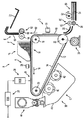
図1に、電子写真印刷装置の一例8を模式的に示す。この図の電子写真印刷装置8にて使用しているベルト10は、概略、光導電面12及び接地用導電層14を有する光導電ベルト10である。導電層14は例えば薄い金属層か金属化ポリマ層として形成し、その導体部分例えば金属部分を接地した構成とする。光導電面12は、好ましくは、導電層14の上に感光素材を堆積させて電荷発生層及び電荷移送層を形成することにより、形成する。また、図中の矢印付線16はベルト10の進行方向であり、矢印方向16に沿って順々に、各種の処理ステーションが配置されている。従って、ベルト10をその進行方向16に沿って動かすことにより、ベルト10の光導電面12の各部をそれらの処理ステーションに順繰りに送り込むことができる。更に、ベルト10はストリッピングローラ18、テンショニングローラ20及びドライブローラ22に架けられている。それらのうちドライブローラ22は、架かっているベルト10を先送りするために実装されている回動可能な部材であり、このローラ22に連結されているモータ24を回転駆動することによりこのローラ22を回転させ矢印方向16に沿ってベルト10を先送りすることができる。ローラ22とモータ24とを連結する手段としては、例えばドライブベルト等、それに適する部材を用いる。更に、ベルト10が張力状態即ちぴんと張られた状態を保つよう、テンショニングローラ20は図示しない一対のバネの弾性力によってベルト10に押しつけられ、ベルト10に適当な力を加えている。なお、ストリッピングローラ18及びテンショニングローラ20は、自在に回転できるように実装されている。
FIG. 1 schematically shows an example 8 of an electrophotographic printing apparatus. The belt 10 used in the
矢印方向16に沿ってベルト10を先送りするとき光導電面12の各部が最初に通るのは、コロナ発生装置26が設けられている帯電ステーションAである。コロナ発生装置26は、ベルト10の光導電面12を実質的に均一電位になるよう帯電させる。目標とする電位は比較的高い電位である。光導電面12のうち、帯電ステーションAにおける均一帯電を終えた部分は、続いて露出ステーションBへと送られる。
When the belt 10 is advanced along the
露出ステーションBには、コンピュータ等の画像信号源から供給される画像信号を処理して形態変換するコントローラ、例えばESS(Electronic SubSystem)28が設けられている。ESS28に供給される画像信号は出力したい画像を表す信号であるが、連続階調表現(グレースケール表現)されておらずそのままでは変調出力発生器を駆動できない場合があるため、ESS28にて当該当該画像信号を受け取って処理し、連続階調画像乃至グレースケール画像を表す画像強度信号の形態に変換する。なお、ESS28は専用ミニコンピュータによって実現しこの図の電子写真印刷装置8に内蔵させるとよい。また、ESS28に画像信号を送る画像信号源例えばコンピュータは、この図の電子写真印刷装置8に近接配置されていてもよいし遠隔配置されていてもよい。また、1台であってもよいし複数台であってもよい。従って、遠隔配置されている複数台のコンピュータによりこの図の電子写真印刷装置8を共用することもできるし、1台の高速コンピュータによりこの図の電子写真印刷装置8を専用することもできる。何れにせよ、印刷すべき画像を示す連続階調画像信号は、ESS28から変調出力発生器例えばROS(Raster Output Scanner)30に送られる。ROS30は、レーザ光源からの輻射光を回転ポリゴン鏡ブロックにより反射させその反射光により光導電ベルト10の帯電部分をラスタバイラスタベースで走査する構成として実現することも、またアレイを形成するよう配置された複数個のLED(Light Emitting Diode)からの輻射光により光導電ベルト10の帯電部分をラスタバイラスタベースで走査する構成として実現することも、可能である。ROS30は、ESS28から受け取った連続階調画像信号に従い、例えば300画素/インチ以上の解像度で光導電ベルト10の帯電部分に輻射光を照射することにより、光導電ベルト10を露出、露光してその光導電面12上に静電潜像を記録、形成する(1インチ=約2.54×10-2m)。
The exposure station B is provided with a controller, for example, an ESS (Electronic SubSystem) 28, that processes and converts an image signal supplied from an image signal source such as a computer. The image signal supplied to the ESS 28 is a signal representing an image to be output. However, since there is a case where the modulation output generator cannot be driven without being expressed in continuous tone (grayscale expression), the ESS 28 An image signal is received and processed, and converted into a form of an image intensity signal representing a continuous tone image or a gray scale image. Note that the ESS 28 may be realized by a dedicated minicomputer and built in the
露出ステーションBの別の実現形態或いはESS28の別の使用形態としては、ESS28に画像信号源としてRIS(Raster Input Scanner)を接続する、という形態がある。RISは、原稿が載置される原稿台、その原稿を照明するランプ、光が通る光学系、原稿を照明光で走査するための走査ドライブ、原稿からの反射光を検知する光検知素子群例えばCCD(Charge Coupled Device)アレイ等によって構成できる装置である。その主たる機能は、原稿全体を捉えてラスタ走査することにより、一群のラスタ走査線からなりその原稿全体の像を示す信号を生成し(ラスタ変換)、このラスタ変換によって得られた一群の電気信号即ちラスタ走査結果信号をESS28に送る、という機能である。ESS28は、RISから送られてくる信号を処理してグレースケール表現の画像強度信号に変換し、ROS30に送る。ROS30は、ESS28から送られてくるグレースケールの画像強度信号に従い光導電ベルト10の帯電部分を露光させ、それによってその光導電面12上に当該グレースケール画像強度信号に相応する静電潜像を記録、形成する。
As another implementation form of the exposure station B or another use form of the ESS 28, there is a form in which an RIS (Raster Input Scanner) is connected to the ESS 28 as an image signal source. The RIS is a document table on which a document is placed, a lamp that illuminates the document, an optical system through which light passes, a scanning drive for scanning the document with illumination light, and a group of light detection elements that detect reflected light from the document. It is a device that can be constituted by a CCD (Charge Coupled Device) array or the like. Its main function is to capture the entire original and perform raster scanning, thereby generating a signal consisting of a group of raster scanning lines and indicating the image of the entire original (raster conversion), and a group of electrical signals obtained by this raster conversion. That is, the raster scanning result signal is sent to the ESS 28. The ESS 28 processes the signal sent from the RIS, converts it into a grayscale image intensity signal, and sends it to the
光導電面12上に記録、形成された静電潜像は、ベルト10の進行によって現像ステーションCに送り込まれる。現像ステーションCでは、液状又は乾燥粒子状のトナーを周知手法で静電潜像に静電吸着させる。図中の現像ステーションCは、現像素材を送出し静電潜像に接触させる現像ユニットとして、2個の磁気ブラシ形成用現像ローラ40及び42を備える磁気ブラシ形成型現像システム38を備えている。この現像システム38の現像ローラ40及び42は、キャリア細粒及びトナー粒子からなる現像素材を送出し、当該現像素材からなり外向きに延びるブラシ状の物体即ち磁気ブラシを形成する。光導電面12上の静電潜像はこの磁気ブラシに接触し、磁気ブラシ中にキャリア細粒を残してトナー粒子を吸着するので、光導電面12上にはトナー粒子による粉体像即ちトナー像が形成されることとなる。また、こうして光導電面12上の静電潜像を現像していくにつれトナー粒子は費消され現像素材中のトナー粒子量が減っていくが、それを補うべく設けられているトナー粒子吐出器44からの吐出により、現像ユニット38の現像器ハウジング46内にトナー粒子が補給される。
The electrostatic latent image recorded and formed on the photoconductive surface 12 is sent to the developing station C as the belt 10 advances. In the developing station C, liquid or dry toner particles are electrostatically adsorbed to the electrostatic latent image by a known method. The developing station C in the drawing includes a magnetic brush forming type developing system 38 including two magnetic brush forming developing rollers 40 and 42 as a developing unit for sending a developing material and bringing it into contact with an electrostatic latent image. The developing rollers 40 and 42 of the developing system 38 send out a developing material composed of carrier fine particles and toner particles, and form a brush-like object or magnetic brush made of the developing material and extending outward. The electrostatic latent image on the photoconductive surface 12 is in contact with the magnetic brush, and the toner particles are adsorbed leaving the carrier fine particles in the magnetic brush. An image will be formed. Further, as the electrostatic latent image on the photoconductive surface 12 is developed in this way, the toner particles are consumed and the amount of toner particles in the developing material decreases, but the
同じく図1に示されているように、静電潜像の現像によりベルト10上に形成されたトナー像は、ベルト10の進行に伴い転写ステーションDへと送り込まれる。この転写ステーションDには印刷先となる媒体シート48も送り込まれてくる。この図では、シート送給装置50によって転写ステーションDに媒体シート48が送り込まれているが、後に図2を参照して説明するように、他のマーキングエンジンから媒体シート48を受け取って転写ステーションDに送り込む装置もまたシート送給装置であるといえる。また、図1に例示されているシート送給装置50は、電子写真印刷装置8の入口であるシートスタック54の一番上にある媒体シート48に接触し、それを引き込むナジャロール52を備えている。ナジャロール52が回転するとその作用によってシートスタック54の一番上にある媒体シート48がリタードフィーダアセンブリ80に送られる。リタードフィーダアセンブリ80はフィードローラ(ドライブローラ)82及びリタードローラ84を備えており、ナジャロール52によって送り込まれた媒体シート48はこれらのローラ82及び84の動作によってシュート56内に送り込まれる。シュート56内に送り込まれた支持基体(媒体)シート48はそのシュート56内を通って先に送られる。そのタイミングは、ベルト10の光導電面12上に形成されているトナー像が、転写ステーションDにて媒体シート48に接触することとなるように、制御される。両者が接触する転写ステーションDには、媒体シート48の背面にイオンをスプレーするコロナ発生装置58等が設けられている。トナー像と接触している媒体シート48の背面にイオンがスプレーされると、トナー像は光導電面12から媒体シート48上へと吸引される。こうしてトナー像が転写された媒体シート48は、引き続き矢印付線60に沿って動いて図示しないコンベアに乗り、そのコンベアにより融着ステーションEに運ばれていく。融着ステーションEには、媒体シート48に転写された粉体像をその媒体シート48に永久固着させるため、フューザアセンブリ62が設けられている。フューザアセンブリ62は、熱せられたフューザローラ64及びそれと差し向かいのバックアップローラ66を備えている。媒体シート48は、トナー像被着面をフューザローラ64に接触させつつフューザローラ64とバックアップローラ66の間を通過していく。このようにしてトナー像が永久固着された後、媒体シート48はシュート68を介して装置出口例えば排紙トレイ72へと送り込まれ、電子写真印刷装置8のオペレータに引き渡される。他方、媒体シート48が離れていった後、ベルト10の光導電面12は清掃ステーションFへと進み、その上に残存している現像素材特にトナー粒子や、同じく残存している紙の微細繊維が、当該清掃ステーションFにて光導電面12から除去される。清掃ステーションFは、例えば、光導電面12に接触するよう実装された繊維質の回転ブラシによって光導電面12上にある紙の微細繊維を攪乱除去し、また媒体シート48に転写されないまま光導電面12上に残ったトナー粒子等を清掃ブレードにより除去する構成を有している。清掃ブレードのポジションはワイパーポジションとしてもよいしドクターポジションとしてもよい。何れにするかは用途次第である。清掃後は、前述の均一帯電処理から始まる次の画像形成サイクルを開始するのに先立って、図示しない放電ランプからの光により光導電面12をくまなく照射し、それによって光導電面12上の残留静電荷を散逸、霧散させる。
Similarly, as shown in FIG. 1, the toner image formed on the belt 10 by the development of the electrostatic latent image is sent to the transfer station D as the belt 10 advances. A medium sheet 48 serving as a printing destination is also sent to the transfer station D. In this figure, the media sheet 48 is fed to the transfer station D by the sheet feeding device 50. However, as will be described later with reference to FIG. 2, the media sheet 48 is received from another marking engine and transferred to the transfer station D. It can be said that the device fed into the sheet is also a sheet feeding device. Further, the sheet feeding apparatus 50 illustrated in FIG. 1 includes a nudger roll 52 that comes into contact with and pulls in the media sheet 48 at the top of the sheet stack 54 that is the entrance of the
以上、電子写真印刷装置の全体動作について、本願の目的から見て十分な程度に説明を行った。次に、この説明に基づき本発明の特徴部分に関し説明する。 The overall operation of the electrophotographic printing apparatus has been described to a sufficient extent in view of the purpose of the present application. Next, a characteristic part of the present invention will be described based on this description.
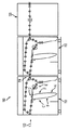
図2に、複数個のモジュールを縦続連結したアーキテクチャを有する印刷システム100を示す。図中、図1に示したものと同様の部材はシングルプライム(’)を添えた参照符号により、また図1に示していない部材は新たな参照符号により、それぞれ表してある。この印刷システム100は、マーキングエンジンを複数個(図では110及び112の2個)直列配置し、タンデム連結手段114により縦続連結したタンデム型のシステムであり、一方のマーキングエンジン110から他方のマーキングエンジン112へと媒体シート48を直に送り込むことができ、その際必要に応じて媒体シート48を表裏反転させることができる。また、この図の印刷システム100は複数個のマーキングエンジン110,112を横方向に並べてフレームに組み込んだ水平フレーム構造を採用しているが、縦方向に並べて組み込む垂直フレーム構造を採用することも、或いは水平フレーム構造と垂直フレーム構造を組み合わせた構造を採用することもできる。それら変形版構成も本発明の技術的範囲に属することは、ご理解の通りである。更に、この図の印刷システム100を構成するマーキングエンジンの個数は110,112の2個であるが、水平フレーム構造や垂直フレーム構造をかたちづくるマーキングエンジンの個数は何個でもよい。この点もご理解頂けるであろう。
FIG. 2 shows a
この印刷システム100は、通常時は第1動作モードにて動作する。第1動作モードとは、タンデム型のシステム100を構成するよう直列配置及び縦続接続された2個のマーキングエンジン110,112が協働して印刷を行うモードである。このモードで動作しているときに仮にマーキングエンジン110,112のうち一方に何らかの不具合、例えば故障が発生した場合、サービスパーソンの来訪を依頼し待機する必要がある。サービスパーソンの来訪を待つ間、マーキングエンジン110,112の何れも使用できない状態が続くこともあるが、この印刷システム100においては、場合によって、片方だけなら継続使用できるようにしている。即ち、この印刷システム100を対象とする制御システム内には、特定種類の不具合(例えば特定種類の故障)を検知でき従ってその発生元を特定できる故障検知ソフトウェアが組み込まれている。従って、マーキングエンジン110,112のうち一方にて不具合が発生した場合、発生した不具合がこの故障検知ソフトウェアにて検知できる種類の不具合であったなら、故障検知ソフトウェアによってその事実を検知して発生元を特定でき、従って制御システムはその不具合に対処することができる。特徴的なことに、この印刷システム100で採用している対処法は、故障検知ソフトウェアによって当該特定種類の不具合が検知されたとき、制御システムが印刷システム100の動作モードを第1動作モードから第2動作モードへと自動的に切り替える、という対処法である。第2動作モードとは、不具合発生元を抱えたマーキングエンジン(110又は112)即ち不調乃至故障部分を有するマーキングエンジンを媒体シート48がただ単に通り抜けていくよう、当該不調部分を有するマーキングエンジンを動作させるモードである。第2動作モードでは、例えば、あるマーキングエンジンのフューザアセンブリ62に不調が生じた場合、そのフューザアセンブリ62のニップ(フューザローラ64とバックアップローラ66の隙間)を開き又はそのフューザアセンブリ62を冷まし、その状態で媒体シート48を通過させる、等といったユニークな動作が実行される。こうしたユニークな動作は、不具合発生元を抱えたマーキングエンジンに対し制御システムが適当な処置、調整を施すこと、例えばフューザアセンブリ62のニップを拡げるためのアンカム動作を実行させることによって、当該マーキングエンジンに行わせることができる。また、この対処法によって対処することができる不具合の種類(上述の“特定種類の不具合”)は、不具合発生元を抱えたマーキングエンジン内を媒体シート48が通り抜けるのに支障がないような種類である。特に、不具合が発生したサブシステム例えば故障したフューザアセンブリ62にアクセスしてその不具合の調査或いは解消を図ることができる種類であるとよい。更に、この対処法は、各マーキングエンジン110,112の帯電ステーションA’、露出ステーションB’、そのROS、現像ステーションC’、転写ステーションD’、融着ステーションE’及び清掃ステーションF’の何れにおいて生じた不具合に対しても適用でき、またそれらのサブシステムのうち複数箇所で同時に不具合が生じた場合にも有効である。こうして第2動作モードに切り替わった後は、媒体シート48は不具合発生元を抱えたマーキングエンジン(例えば110)を通り過ぎ、次段の装置例えばまだ適正に機能している次のマーキングエンジン(例えば112)或いは更に仕上げ装置120に到達して、到達先の装置にて適宜処理される。この状態、即ち第2動作モードでの動作は、例えばサービスパーソンが来訪するまで継続される。
The
制御システムによる動作モードの切替は、このように自動的に行うだけでなく、装置オペレータからの指示によって行うこともできる。即ち、第1動作モードでの動作中にマーキングエンジン110,112の何れかにて特定種類の不具合が発生したことを検知したとき、媒体シート48がそのマーキングエンジンを通過するよう自動的に第2動作モードに切り替える、という形態だけでなく、装置オペレータから指示があったとき、媒体シート48がマーキングエンジン110,112のうち所定の又は装置オペレータから指定されたものを通過するよう第2動作モードに切り替える、という形態での動作モード切替も実行可能である。また、印刷システム100を構成するマーキングエンジン(図では110,112)のうち何れか1個でも両面印刷機能を有しているなら、第2動作モードでそれを活用し片面印刷及び両面印刷を継続実行できる可能性がある。例えば、第1動作モードによる通常動作時には、各マーキングエンジン110,112の片面印刷機能を用いて片面印刷及び両面印刷を実行し、第2動作モードでの動作時には、適正に機能し得るマーキングエンジンの中に両面印刷機能を有するものがあればそれを用いて引き続き、片面印刷及び両面印刷を実行する、といった具合である。また、制御システムによる“特定種類の不具合”の検知は、例えば、不具合発生元を抱えたマーキングエンジンに媒体シート通過不能状態が生じているかどうかについての検知を含む形態で、実行することができる。制御システムは、不具合発生元を抱えたマーキングエンジンに媒体シート通過不能状態が生じていないことを検知した場合、他の正常動作可能なマーキングエンジンからやってくる媒体シート48が当該不調なマーキングエンジンを通り抜けることができるよう、或いは当該不調なマーキングエンジン内の媒体シート48を他の正常動作可能なマーキングエンジンへと通すことができるよう、当該不調なマーキングエンジンのサブシステム乃至構成要素のうち要所要所を引き続き動作させる(例えばフューザアセンブリ62のニップを開き或いは冷ましつつベルト10の進行等の動作は通常通り行わせる)。印刷システム100は、第2動作モードへの切り替わりによって通常動作時より低機能な状態とはなるものの、サービスパーソンが来訪するまでその動作を継続可能であり、従ってそれまでその使用を継続することができる。
The switching of the operation mode by the control system can be performed not only automatically as described above but also by an instruction from the apparatus operator. That is, when it is detected that a specific type of malfunction has occurred in either of the marking
以上説明した印刷システム100は、複数個のマーキングエンジン110,112を使用するシステムである。このように同一印刷システム内で複数個のマーキングエンジンを使用できるアーキテクチャにおいては、第1動作モードにおいて、シングルパス両面印刷、内部パス両面印刷及びマルチパス印刷を実行することができる。ここでいうシングルパス両面印刷とは、あるマーキングエンジン(例えば110)にて媒体シート48の片面に印刷した後、別のマーキングエンジン(例えば112)にて他面に印刷することによって、媒体シート48の両面に印刷する動作のことであり、媒体シート48を最初のマーキングエンジン(例えば110)に再循環する挙動を伴わない。これに対して、内部パス両面印刷とは、あるマーキングエンジン(例えば110)にて媒体シート48の片面に印刷した後、同じマーキングエンジン(例えば110)に戻して再循環させ他面に印刷することによって、媒体シート48の両面に印刷する動作のことである。そして、マルチパス印刷とは、あるマーキングエンジン(例えば110)にて媒体シート48の片面に印刷した後、別のマーキングエンジン(例えば112)にてその面と同じ面に印刷する動作のことである。
The
また、マーキングエンジン110,112内で媒体シート48が辿る経路には、マーキングエンジン入口経路及びマーキングエンジン出口経路が含まれる。例えばマーキングエンジン110の出口経路は図2中の連結手段114のすぐ左側の部分、マーキングエンジン112の入口経路は連結手段114のすぐ右側の部分である。これらの経路部分は、例えばマーキングエンジン(例えば110)から別のマーキングエンジン(例えば112)へと媒体シート48を引き渡す際に使用される。即ち、送給元のマーキングエンジンの出口経路から出た媒体シート48が送給先のマーキングエンジンの入口経路に送り込まれる。また、連結手段114の前又は後に媒体シート48を表裏反転させる経路部分を設けてもよい。この反転経路は、図2中のマーキングエンジン110では、融着ステーションE’の右、連結手段114の左にあり、縦に延びている。こうした経路部分があれば、必要な場合に媒体シート48の向きを反転させることができ、必要なければ反転無しで後段に送ることができる。更に、マーキングエンジン110,112内で媒体シート48が辿る経路には、必須ではないが、両面印刷用内部ループを設けることができる。図2中では、マーキングエンジン上部を通り出口経路から入口経路に戻っている経路部分が、これに当たる。印刷システム100を構成するマーキングシステムの中に、両面印刷用内部ループを有するマーキングエンジンがある場合、何個かのマーキングエンジンが故障し印刷システム100が第2動作モードに切り替わったときでも、両面印刷用内部ループ付マーキングエンジンが故障せずに残っていれば、そのマーキングエンジンを用いて両面印刷を継続することができる。
Further, the path followed by the media sheet 48 in the marking
更に、上述したアーキテクチャにおいては、同一の印刷システム内で様々なマーキングエンジンを使用することができる。即ち、前述の通り、その種類や処理速度が異なる様々なマーキングエンジンを使用することができる。また、上述したアーキテクチャにおいては、システム構成がモジュール化されているため各マーキングエンジン及びその内部で媒体シート48が辿る経路に冗長性があり、例えば何れかのマーキングエンジンの両面印刷用内部ループをバックアップとして利用し第2動作モードにて両面印刷を継続実行することができる。そして、上述のアーキテクチャは、印刷システム100の入口に設ける媒体シート供給源122の個数や、出口に設ける出力統合モジュール(仕上げ装置120)の個数は、それぞれ1個でよい。
Further, in the architecture described above, various marking engines can be used within the same printing system. That is, as described above, various marking engines having different types and processing speeds can be used. In the architecture described above, since the system configuration is modularized, each marking engine and the path along which the media sheet 48 follows have redundancy, and for example, the internal loop for duplex printing of any marking engine is backed up. And double-sided printing can be continuously executed in the second operation mode. In the above-described architecture, the number of media
8 電子写真印刷装置、30 ROS、48 媒体シート、54 シートスタック(装置入口)、62 フューザアセンブリ、72 排紙トレイ(装置出口)、100 印刷システム、110,112 マーキングエンジン、114 タンデム連結手段、122 媒体シート供給源、A、A’ 帯電ステーション、B,B’ 露出ステーション、C,C’ 現像ステーション、D,D’ 転写ステーション、E,E’ 融着ステーション、F,F’ 清掃ステーション。 8 Electrophotographic printing apparatus, 30 ROS, 48 Media sheet, 54 Sheet stack (apparatus inlet), 62 Fuser assembly, 72 Discharge tray (apparatus outlet), 100 Printing system, 110, 112 Marking engine, 114 Tandem connecting means, 122 Media sheet supply source, A, A 'charging station, B, B' exposure station, C, C 'developing station, D, D' transfer station, E, E 'fusing station, F, F' cleaning station.
Claims (5)
本印刷システムの動作モードとして、少なくとも2個のIMEに媒体を通しそれらIMEを任意に使用してその媒体にマーキングする第1動作モードと、第1動作モードにて使用されたIMEそれぞれに媒体を通すがそのうち所定種類不具合の発生が検知されたIMEは単に通過させるだけにし残りのIMEを使用してその媒体にマーキングする第2動作モードと、を有し、
制御システムが、IMEのうち1個にて所定種類不具合が発生したことを検知した場合に、当該不具合が発生したIMEが通過のみとされるよう第2動作モードにて本印刷システムを動作させる統合型の印刷システム。 A plurality of IMEs arranged in series, and a control system capable of detecting the occurrence of a predetermined type of failure in those IMEs;
As an operation mode of the present printing system, a medium is passed through at least two IMEs and the IME is arbitrarily used to mark the medium, and a medium is placed in each of the IMEs used in the first operation mode. A second mode of operation in which an IME in which the occurrence of a predetermined type of failure is detected is simply passed through and the medium is marked using the remaining IME;
Integration in which the printing system is operated in the second operation mode when the control system detects that a predetermined type of failure has occurred in one of the IMEs so that the IME in which the failure has occurred is only passed. Mold printing system.
媒体送給源から少なくとも1個のIMEに媒体を送給して少なくとも2個のIMEに媒体を通し、媒体が通るIMEを任意に使用してその媒体にマーキングする第1動作モードから、
第1動作モードで使用される各IMEに媒体を通すがそのうち少なくとも1個は単に通過させるだけにし残りのIMEを使用してその媒体にマーキングする第2動作モードへと、
切り替える媒体印刷方法。 Executed in an integrated printing system comprising a plurality of IMEs arranged in series,
From a first mode of operation in which media is fed from a media source to at least one IME to pass the media through at least two IMEs, optionally marking the media using the IME through which the media passes;
Pass the media through each IME used in the first mode of operation, but only pass at least one of them, and use the remaining IMEs to mark the media, to the second mode of operation.
Media printing method to switch.
少なくとも2個のIMEに媒体を通しそれらIMEを任意に使用してその媒体にマーキングする第1動作モードを実行する手段と、
第1動作モードにて使用されたIMEそれぞれに媒体を通すがそのうち少なくとも1個は単に通過させるだけにし残りのIMEを使用してその媒体にマーキングする第2動作モードを実行する手段と、
を備える統合型の印刷システム。 A plurality of IMEs arranged in series;
Means for passing a medium through at least two IMEs and optionally using the IMEs to perform a first mode of operation for marking the medium;
Means for passing a medium through each IME used in the first mode of operation, at least one of which is simply passed through, and performing a second mode of operation for marking the medium using the remaining IMEs;
Integrated printing system with
それらIMEにて帯電、露出、ROS、現像、転写、融着及び清掃のうち少なくとも1個に係る所定種類の不具合が発生したことを検知する手段と、
少なくとも2個のIMEに媒体を通しそれらIMEを任意に使用してその媒体にマーキングする第1動作モードを実行する手段と、
第1動作モードにて使用されたIMEそれぞれに媒体を通すがそのうち少なくとも1個は単に通過させるだけにし残りのIMEを使用してその媒体にマーキングする第2動作モードを実行する手段と、
を備え、検知結果に応じ第1又は第2動作モードを実行する統合型の印刷システム。 A plurality of IMEs arranged in series;
Means for detecting the occurrence of a predetermined type of failure related to at least one of charging, exposure, ROS, development, transfer, fusing and cleaning in the IME;
Means for passing a medium through at least two IMEs and optionally using the IMEs to perform a first mode of operation for marking the medium;
Means for passing a medium through each IME used in the first mode of operation, at least one of which is simply passed through, and performing a second mode of operation for marking the medium using the remaining IMEs;
And an integrated printing system that executes the first or second operation mode according to the detection result.
少なくとも2個のIMEに媒体を通しそれらIMEを任意に使用してその媒体にマーキングする第1動作モードを実行する手段と、
第1動作モードにて使用されたIMEそれぞれに媒体を通すがそのうち少なくとも1個は単に通過させるだけにし残りのIMEを使用してその媒体にマーキングする第2動作モードを実行する手段と、
を備え、第2動作モードでは、媒体を単に通過させるだけのIMEにおけるフューザのニップを拡げる統合型の印刷システム。 A plurality of IMEs arranged in series;
Means for passing a medium through at least two IMEs and optionally using the IMEs to perform a first mode of operation for marking the medium;
Means for passing a medium through each IME used in the first mode of operation, at least one of which is simply passed through, and performing a second mode of operation for marking the medium using the remaining IMEs;
And in the second mode of operation, an integrated printing system that widens the nip of the fuser in the IME that simply allows media to pass through.
Applications Claiming Priority (1)
| Application Number | Priority Date | Filing Date | Title |
|---|---|---|---|
| US11/287,177 US7280771B2 (en) | 2005-11-23 | 2005-11-23 | Media pass through mode for multi-engine system |
Publications (2)
| Publication Number | Publication Date |
|---|---|
| JP2007145017A true JP2007145017A (en) | 2007-06-14 |
| JP2007145017A5 JP2007145017A5 (en) | 2010-01-07 |
Family
ID=38053667
Family Applications (1)
| Application Number | Title | Priority Date | Filing Date |
|---|---|---|---|
| JP2006312344A Pending JP2007145017A (en) | 2005-11-23 | 2006-11-20 | Multi-engine system with media pass through mode |
Country Status (2)
| Country | Link |
|---|---|
| US (1) | US7280771B2 (en) |
| JP (1) | JP2007145017A (en) |
Cited By (3)
| Publication number | Priority date | Publication date | Assignee | Title |
|---|---|---|---|---|
| JP2009278484A (en) * | 2008-05-16 | 2009-11-26 | Ricoh Co Ltd | Image forming apparatus, image formation control method, image formation control program and recording medium |
| JP2011145606A (en) * | 2010-01-18 | 2011-07-28 | Canon Inc | Image forming system, control method of the same, control program, and recording medium |
| JP2011145603A (en) * | 2010-01-18 | 2011-07-28 | Canon Inc | Image forming system, control method of the same, control program, and recording medium |
Families Citing this family (10)
| Publication number | Priority date | Publication date | Assignee | Title |
|---|---|---|---|---|
| JP4816284B2 (en) * | 2006-06-26 | 2011-11-16 | コニカミノルタビジネステクノロジーズ株式会社 | Image forming apparatus control method and image forming apparatus |
| JP4535073B2 (en) * | 2007-02-22 | 2010-09-01 | 富士ゼロックス株式会社 | Image processing apparatus and program |
| JP2008209992A (en) * | 2007-02-23 | 2008-09-11 | Fuji Xerox Co Ltd | Image processor and program |
| US8169657B2 (en) * | 2007-05-09 | 2012-05-01 | Xerox Corporation | Registration method using sensed image marks and digital realignment |
| US8203750B2 (en) | 2007-08-01 | 2012-06-19 | Xerox Corporation | Color job reprint set-up for a printing system |
| US7697166B2 (en) * | 2007-08-03 | 2010-04-13 | Xerox Corporation | Color job output matching for a printing system |
| US8200140B2 (en) * | 2009-04-16 | 2012-06-12 | Xerox Corporation | Modular printing system having a module with a bypass path |
| JP2011137957A (en) * | 2009-12-28 | 2011-07-14 | Canon Inc | Apparatus and method for printing, and program for executing the method |
| JP5511548B2 (en) * | 2010-06-30 | 2014-06-04 | キヤノン株式会社 | Image forming apparatus |
| EP2920651B1 (en) * | 2012-11-13 | 2019-09-18 | HP Indigo B.V. | Formation of a crease and an image on media |
Citations (5)
| Publication number | Priority date | Publication date | Assignee | Title |
|---|---|---|---|---|
| JPH05138949A (en) * | 1991-08-26 | 1993-06-08 | Oki Electric Ind Co Ltd | Automatic passbook transaction apparatus |
| JPH08174809A (en) * | 1994-12-22 | 1996-07-09 | Canon Inc | Image forming apparatus and method therefor |
| JPH09127739A (en) * | 1995-09-29 | 1997-05-16 | Xerox Corp | One-side or double-side printing system making use of inverting double-side path |
| JPH1170721A (en) * | 1997-08-29 | 1999-03-16 | Tec Corp | Printer device |
| JP2004013038A (en) * | 2002-06-10 | 2004-01-15 | Ricoh Co Ltd | Image forming apparatus |
Family Cites Families (60)
| Publication number | Priority date | Publication date | Assignee | Title |
|---|---|---|---|---|
| US4579446A (en) | 1982-07-12 | 1986-04-01 | Canon Kabushiki Kaisha | Both-side recording system |
| US4587532A (en) | 1983-05-02 | 1986-05-06 | Canon Kabushiki Kaisha | Recording apparatus producing multiple copies simultaneously |
| JP2590477B2 (en) | 1987-05-13 | 1997-03-12 | 富士ゼロックス株式会社 | Paper transport direction change device |
| US4836119A (en) | 1988-03-21 | 1989-06-06 | The Charles Stark Draper Laboratory, Inc. | Sperical ball positioning apparatus for seamed limp material article assembly system |
| JP2636441B2 (en) | 1989-11-09 | 1997-07-30 | 富士ゼロックス株式会社 | Image recording device |
| US5095342A (en) | 1990-09-28 | 1992-03-10 | Xerox Corporation | Methods for sheet scheduling in an imaging system having an endless duplex paper path loop |
| US5080340A (en) | 1991-01-02 | 1992-01-14 | Eastman Kodak Company | Modular finisher for a reproduction apparatus |
| US5159395A (en) | 1991-08-29 | 1992-10-27 | Xerox Corporation | Method of scheduling copy sheets in a dual mode duplex printing system |
| US5272511A (en) | 1992-04-30 | 1993-12-21 | Xerox Corporation | Sheet inserter and methods of inserting sheets into a continuous stream of sheets |
| US5358238A (en) | 1993-04-27 | 1994-10-25 | Xerox Corporation | Shared user printer output dynamic "mailbox" system |
| US5326093A (en) | 1993-05-24 | 1994-07-05 | Xerox Corporation | Universal interface module interconnecting various copiers and printers with various sheet output processors |
| US5473419A (en) | 1993-11-08 | 1995-12-05 | Eastman Kodak Company | Image forming apparatus having a duplex path with an inverter |
| US5596416A (en) | 1994-01-13 | 1997-01-21 | T/R Systems | Multiple printer module electrophotographic printing device |
| US5525031A (en) | 1994-02-18 | 1996-06-11 | Xerox Corporation | Automated print jobs distribution system for shared user centralized printer |
| US5778377A (en) | 1994-11-04 | 1998-07-07 | International Business Machines Corporation | Table driven graphical user interface |
| US5570172A (en) | 1995-01-18 | 1996-10-29 | Xerox Corporation | Two up high speed printing system |
| US5557367A (en) | 1995-03-27 | 1996-09-17 | Xerox Corporation | Method and apparatus for optimizing scheduling in imaging devices |
| US5489969A (en) | 1995-03-27 | 1996-02-06 | Xerox Corporation | Apparatus and method of controlling interposition of sheet in a stream of imaged substrates |
| US5504568A (en) | 1995-04-21 | 1996-04-02 | Xerox Corporation | Print sequence scheduling system for duplex printing apparatus |
| US5629762A (en) | 1995-06-07 | 1997-05-13 | Eastman Kodak Company | Image forming apparatus having a duplex path and/or an inverter |
| US5710968A (en) | 1995-08-28 | 1998-01-20 | Xerox Corporation | Bypass transport loop sheet insertion system |
| US5568246A (en) | 1995-09-29 | 1996-10-22 | Xerox Corporation | High productivity dual engine simplex and duplex printing system using a reversible duplex path |
| US6297886B1 (en) | 1996-06-05 | 2001-10-02 | John S. Cornell | Tandem printer printing apparatus |
| US6476923B1 (en) | 1996-06-05 | 2002-11-05 | John S. Cornell | Tandem printer printing apparatus |
| US6493098B1 (en) | 1996-06-05 | 2002-12-10 | John S. Cornell | Desk-top printer and related method for two-sided printing |
| US5995721A (en) | 1996-10-18 | 1999-11-30 | Xerox Corporation | Distributed printing system |
| US6059284A (en) | 1997-01-21 | 2000-05-09 | Xerox Corporation | Process, lateral and skew sheet positioning apparatus and method |
| US5884910A (en) | 1997-08-18 | 1999-03-23 | Xerox Corporation | Evenly retractable and self-leveling nips sheets ejection system |
| US6210813B1 (en) | 1998-09-02 | 2001-04-03 | Micron Technology, Inc. | Forming metal silicide resistant to subsequent thermal processing |
| US6125248A (en) | 1998-11-30 | 2000-09-26 | Xerox Corporation | Electrostatographic reproduction machine including a plurality of selectable fusing assemblies |
| IT1308720B1 (en) | 1999-06-08 | 2002-01-10 | Tecnau Srl | DYNAMIC SEQUENCER FOR PRINTED SHEETS OF PAPER |
| US6241242B1 (en) | 1999-10-12 | 2001-06-05 | Hewlett-Packard Company | Deskew of print media |
| US6384918B1 (en) | 1999-11-24 | 2002-05-07 | Xerox Corporation | Spectrophotometer for color printer color control with displacement insensitive optics |
| US6577925B1 (en) | 1999-11-24 | 2003-06-10 | Xerox Corporation | Apparatus and method of distributed object handling |
| US7864346B2 (en) | 2000-05-16 | 2011-01-04 | Xerox Corporation | Apparatus and method for describing, planning and automatically programming complex finishing tasks |
| US6450711B1 (en) | 2000-12-05 | 2002-09-17 | Xerox Corporation | High speed printer with dual alternate sheet inverters |
| US6550762B2 (en) | 2000-12-05 | 2003-04-22 | Xerox Corporation | High speed printer with dual alternate sheet inverters |
| US6633790B2 (en) | 2001-01-29 | 2003-10-14 | Xerox Corporation | Systems and methods for optimizing a production facility |
| US6607320B2 (en) | 2001-03-30 | 2003-08-19 | Xerox Corporation | Mobius combination of reversion and return path in a paper transport system |
| US6554276B2 (en) | 2001-03-30 | 2003-04-29 | Xerox Corporation | Flexible sheet reversion using an omni-directional transport system |
| US6633382B2 (en) | 2001-05-22 | 2003-10-14 | Xerox Corporation | Angular, azimuthal and displacement insensitive spectrophotometer for color printer color control systems |
| US6621576B2 (en) | 2001-05-22 | 2003-09-16 | Xerox Corporation | Color imager bar based spectrophotometer for color printer color control system |
| US6639669B2 (en) | 2001-09-10 | 2003-10-28 | Xerox Corporation | Diagnostics for color printer on-line spectrophotometer control system |
| US6608988B2 (en) | 2001-10-18 | 2003-08-19 | Xerox Corporation | Constant inverter speed timing method and apparatus for duplex sheets in a tandem printer |
| US6612571B2 (en) | 2001-12-06 | 2003-09-02 | Xerox Corporation | Sheet conveying device having multiple outputs |
| US6476376B1 (en) | 2002-01-16 | 2002-11-05 | Xerox Corporation | Two dimensional object position sensor |
| US7233405B2 (en) | 2002-10-30 | 2007-06-19 | Palo Alto Research Center, Incorporated | Planning and scheduling reconfigurable systems with regular and diagnostic jobs |
| US8315898B2 (en) | 2002-10-30 | 2012-11-20 | Palo Alto Research Center, Incorporated | Planning and scheduling reconfigurable systems around off-line resources |
| US7230736B2 (en) | 2002-10-30 | 2007-06-12 | Palo Alto Research Center, Incorporated | Planning and scheduling reconfigurable systems with alternative capabilities |
| US6748186B1 (en) * | 2002-12-09 | 2004-06-08 | Xerox Corporation | Modular machine having distributed fault recovery-assist user interfaces |
| US6944838B2 (en) | 2003-02-03 | 2005-09-13 | Cadence Design Systems, Inc. | Method and system for design verification using proof-partitioning |
| US7093831B2 (en) | 2003-02-04 | 2006-08-22 | Palo Alto Research Center Inc. | Media path modules |
| US20040150156A1 (en) | 2003-02-04 | 2004-08-05 | Palo Alto Research Center, Incorporated. | Frameless media path modules |
| US6895292B2 (en) | 2003-04-28 | 2005-05-17 | Palo Alto Research Center Inc. | Predictive and preemptive planning and scheduling for different job priorities system and method |
| US7139629B2 (en) | 2003-04-28 | 2006-11-21 | Palo Alto Research Center Incorporated | Planning and scheduling for failure recovery system and method |
| US6856845B2 (en) | 2003-04-28 | 2005-02-15 | Palo Alto Research Center Inc. | Monitoring and reporting incremental job status system and method |
| US7226049B2 (en) | 2003-06-06 | 2007-06-05 | Xerox Corporation | Universal flexible plural printer to plural finisher sheet integration system |
| US6819906B1 (en) | 2003-08-29 | 2004-11-16 | Xerox Corporation | Printer output sets compiler to stacker system |
| US6973286B2 (en) | 2004-01-21 | 2005-12-06 | Xerox Corporation | High print rate merging and finishing system for parallel printing |
| US7245838B2 (en) * | 2005-06-20 | 2007-07-17 | Xerox Corporation | Printing platform |
-
2005
- 2005-11-23 US US11/287,177 patent/US7280771B2/en active Active
-
2006
- 2006-11-20 JP JP2006312344A patent/JP2007145017A/en active Pending
Patent Citations (5)
| Publication number | Priority date | Publication date | Assignee | Title |
|---|---|---|---|---|
| JPH05138949A (en) * | 1991-08-26 | 1993-06-08 | Oki Electric Ind Co Ltd | Automatic passbook transaction apparatus |
| JPH08174809A (en) * | 1994-12-22 | 1996-07-09 | Canon Inc | Image forming apparatus and method therefor |
| JPH09127739A (en) * | 1995-09-29 | 1997-05-16 | Xerox Corp | One-side or double-side printing system making use of inverting double-side path |
| JPH1170721A (en) * | 1997-08-29 | 1999-03-16 | Tec Corp | Printer device |
| JP2004013038A (en) * | 2002-06-10 | 2004-01-15 | Ricoh Co Ltd | Image forming apparatus |
Cited By (3)
| Publication number | Priority date | Publication date | Assignee | Title |
|---|---|---|---|---|
| JP2009278484A (en) * | 2008-05-16 | 2009-11-26 | Ricoh Co Ltd | Image forming apparatus, image formation control method, image formation control program and recording medium |
| JP2011145606A (en) * | 2010-01-18 | 2011-07-28 | Canon Inc | Image forming system, control method of the same, control program, and recording medium |
| JP2011145603A (en) * | 2010-01-18 | 2011-07-28 | Canon Inc | Image forming system, control method of the same, control program, and recording medium |
Also Published As
| Publication number | Publication date |
|---|---|
| US7280771B2 (en) | 2007-10-09 |
| US20070116479A1 (en) | 2007-05-24 |
Similar Documents
| Publication | Publication Date | Title |
|---|---|---|
| JP2007145017A (en) | Multi-engine system with media pass through mode | |
| JP4651570B2 (en) | Parallel printing architecture with parallel horizontal printing module | |
| JP4384304B2 (en) | Printing system | |
| US7539432B2 (en) | Image forming apparatus | |
| US5373350A (en) | Xerographic/thermal ink jet combined printing | |
| US6240264B1 (en) | Image output processing apparatus | |
| US7845635B2 (en) | Translating registration nip systems for different width media sheets | |
| US8237962B2 (en) | Throughput estimate based upon document complexity analysis | |
| US8019256B2 (en) | Multi-mode long life monochrome printing system | |
| US7583905B2 (en) | Image forming apparatus and image forming method | |
| JP2000035737A (en) | Image forming device | |
| JP2009258637A (en) | Image forming apparatus and control method for image forming apparatus | |
| US8477327B2 (en) | Scanner registration systems and methods for providing a notification of a scanner re-registration requirement when statistics are outside predetermined registration range | |
| JP2006124180A (en) | Tandem printing system, high-speed printer, and tandem electrophotographic printing system | |
| JP2010109983A (en) | Printing apparatus having common scanning and printing feed path | |
| JPH08137179A (en) | Full color image forming device | |
| US5405723A (en) | Xerographic press capable of simultaneous master making and printing | |
| CN102314132A (en) | Developer, image processing system and image forming method | |
| CN202177783U (en) | High-quality print equipment | |
| JP3134634B2 (en) | Color image forming equipment | |
| JPH09146333A (en) | Color image forming device | |
| JP3857506B2 (en) | Image forming apparatus | |
| US8340546B2 (en) | Dual function charging device and charge patterning device cleaner | |
| JP5617206B2 (en) | Image forming apparatus | |
| JP2005189607A (en) | Image forming apparatus |
Legal Events
| Date | Code | Title | Description |
|---|---|---|---|
| A521 | Request for written amendment filed |
Free format text: JAPANESE INTERMEDIATE CODE: A523 Effective date: 20091116 |
|
| A621 | Written request for application examination |
Free format text: JAPANESE INTERMEDIATE CODE: A621 Effective date: 20091116 |
|
| A977 | Report on retrieval |
Free format text: JAPANESE INTERMEDIATE CODE: A971007 Effective date: 20100910 |
|
| A131 | Notification of reasons for refusal |
Free format text: JAPANESE INTERMEDIATE CODE: A131 Effective date: 20100921 |
|
| A521 | Request for written amendment filed |
Free format text: JAPANESE INTERMEDIATE CODE: A523 Effective date: 20101220 |
|
| A131 | Notification of reasons for refusal |
Free format text: JAPANESE INTERMEDIATE CODE: A131 Effective date: 20110118 |
|
| A521 | Request for written amendment filed |
Free format text: JAPANESE INTERMEDIATE CODE: A523 Effective date: 20110412 |
|
| A02 | Decision of refusal |
Free format text: JAPANESE INTERMEDIATE CODE: A02 Effective date: 20110531 |