JP2007144580A - Position detection device - Google Patents
Position detection device Download PDFInfo
- Publication number
- JP2007144580A JP2007144580A JP2005343802A JP2005343802A JP2007144580A JP 2007144580 A JP2007144580 A JP 2007144580A JP 2005343802 A JP2005343802 A JP 2005343802A JP 2005343802 A JP2005343802 A JP 2005343802A JP 2007144580 A JP2007144580 A JP 2007144580A
- Authority
- JP
- Japan
- Prior art keywords
- limit
- cylinder
- position detection
- moving part
- vibration
- Prior art date
- Legal status (The legal status is an assumption and is not a legal conclusion. Google has not performed a legal analysis and makes no representation as to the accuracy of the status listed.)
- Pending
Links
Images


Abstract
Description
本発明は、例えば、成形機の金型から成形品を取り出す成形品取出機等における移動部位のストロークリミット(進み限、戻り限)への到達を認識可能とする位置検出装置に関するものである。 The present invention relates to a position detection device that can recognize the arrival of a moving part at a stroke limit (advance limit, return limit) in a molded product take-out machine or the like that takes out a molded product from a mold of a molding machine, for example.
例えば、図5に示した旋回型の成形品取出機では、駆動源としてエアシリンダが使用されており、上下方向(Z軸方向)に延設する昇降アーム4に設けた昇降用シリンダ40によって取出ヘッド5を昇降移動させ、また、金型60の開閉方向(Y軸方向)に延設する引抜アーム3に設けた引抜用シリンダ30によって昇降アーム4を金型60の開閉方向(Y軸方向)に進退移動させ、さらに、基部1に軸支した旋回部2にピストンロッドを連結した旋回用シリンダ20によってこの旋回部2を傾けて(X軸及びZ軸方向)引抜アーム3とともに昇降アーム4を旋回移動させるように構成している。
そして、この成形品取出機は、順次に駆動源としての各シリンダ40,30,20を作動して、成形品を把持する取出ヘッド5やこの取出ヘッド5を移動させるアーム3,4等の移動部位を一定範囲に往復移動させて、成形品を成形機の金型60から取り出し成形機外の成形品回収位置まで移送する成形品取出動作を自動的に行う。
The molded product take-out machine sequentially operates the
ところで、成形品取出機は、成形品取出動作のタイミング制御を行うため、取出ヘッド5やアーム3,4等の移動部位におけるストロークリミット(進み限、戻り限)への到達を検出する必要がある。そして、駆動源自体にその位置検出器を持つもの(例えば、サーボモータ)では、各駆動源からの位置検出信号を読み取ることで、成形品取出動作のタイミング制御を行える。しかしながら、駆動源自体に位置検出器を持たないもの(例えば、エアシリンダ、油圧シリンダ、サーボモータ以外の伝動モータ等)では、各駆動源ごとに移動部位の進み限と戻り限の対応位置にリミットセンサ(例えば、近接センサ、リミットスイッチ)がそれぞれ設けられる。
By the way, since the molded product take-out machine performs timing control of the molded product take-out operation, it is necessary to detect the arrival of the stroke limit (advance limit, return limit) at the moving parts such as the take-out
図5に示した上記成形品取出機では、駆動源としてそれ自体に位置検出器を持たないエアシリンダが使用されることから、6個のリミットセンサが設けられている。具体的に、上記成形品取出機は、昇降アーム4においては昇降用シリンダ40のピストンロッドの前進限と後退限とに対応してガイド部材45に近接センサLS1,LS2が2個設けられ、引抜アーム3においては引抜用シリンダ30のピストンロッドの前進限と後退限とに対応して旋回部2内に近接センサLS3,LS4が2個設けられ、旋回部2においては旋回用シリンダ20のピストンロッドの前進限と後退限とに対応してシリンダチューブにシリンダスイッチLS5,LS6が2個設けられている。
In the molded product take-out machine shown in FIG. 5, since an air cylinder having no position detector itself is used as a drive source, six limit sensors are provided. Specifically, in the lifting / lowering arm 4, the molded product take-out machine is provided with two proximity sensors LS1 and LS2 on the
このように、上記成形品取出機では、各駆動源ごとに移動部位のストロークリミットへの到達を検出するだけのためにリミットセンサが多く必要となる不都合がある。そして、センサが多くなると、各センサへの配線(信号線、動力線等)も多くなり、その分センサ配線の断線等のおそれも増大し、さらには、センサに感知させるドグやセンサ取付け部材等のメカ部品も多く必要となり、成形品取出機の製作や部品交換の時に多くの工数、コストがかかる。
本発明は、上記事情に鑑みてなされたものであり、移動部位のストロークリミットへの到達を検出するセンサ数を大幅に削減可能な位置検出装置を実現することを課題とする。
As described above, the molded product take-out machine has a disadvantage that a large number of limit sensors are required only for detecting the arrival of the moving part at the stroke limit for each drive source. And as the number of sensors increases, the wiring to each sensor (signal lines, power lines, etc.) also increases, which increases the risk of disconnection of the sensor wiring, etc. This requires a lot of mechanical parts, and it takes a lot of man-hours and costs when manufacturing and removing parts.
This invention is made | formed in view of the said situation, and makes it a subject to implement | achieve the position detection apparatus which can reduce the number of sensors which detect the arrival to the stroke limit of a movement site | part significantly.
(1)本発明に係る位置検出装置は、駆動源により一定範囲を往復移動させる移動部位の進み限又は戻り限への到達を、その移動部位が停止する際の振動又は傾きによる加速度変化を検出することで認識する手段を設けたことを特徴とするものである(請求項1)。
上記移動部位が進み限又は戻り限へ到達する際には振動を発生させ、また、上記移動部位が進み限又は戻り限へ到達する際にその移動部位が傾き状態となることがある。従って、移動部位が停止する際の振動又は傾きによる加速度変化を検出することで、移動部位の進み限又は戻り限への到達を集約的に認識することができる。その結果、従来、移動部位の進み限、戻り限のそれぞれを直接的に検出していたリミットセンサを無くすか、あるいは初期状態の把握用に進み限又は戻り限のいずれか一方にだけ設けることで足りる。
例えば、XYZ軸方向における移動部位の進み限と戻り限のそれぞれに応じてリミットセンサとしての近接センサを設けて移動部位の進み限又は戻り限への到達を検出していた場合では、このような近接センサを無くすか、進み限又は戻り限のいずれか一方にだけ設けることで足りる。
(1) The position detection device according to the present invention detects an acceleration change due to vibration or tilt when the moving part stops, reaching the advance limit or the return limit of the moving part that is reciprocated within a certain range by the drive source. Thus, a means for recognizing is provided (claim 1).
When the moving part reaches the advance limit or the return limit, a vibration is generated, and when the moving part reaches the advance limit or the return limit, the moving part may be inclined. Therefore, by detecting the acceleration change due to vibration or inclination when the moving part stops, it is possible to collectively recognize the arrival of the moving part to the advance limit or the return limit. As a result, the conventional limit sensor that directly detects the advance limit and return limit of the moving part can be eliminated, or it can be provided only in either the advance limit or return limit for grasping the initial state. It ’s enough.
For example, when a proximity sensor is provided as a limit sensor according to each of the advance limit and return limit of the moving part in the XYZ axis direction, and the arrival of the moving part at the advance limit or return limit is detected, such as It is sufficient to eliminate the proximity sensor or to provide it only at either the advance limit or the return limit.
(2)上記移動部位の停止を停止直前に緩衝させる緩衝機構を設けるようにしてもよい(請求項2)。
この場合、移動部位が停止直前に緩衝機構に当接した時にも振動を発生させるので、移動部位の停止をその直前で認識することができる。従って、次の動作指令を素早く行うことができる。
例えば、移動部位をXYZ軸方向へ移動させる成形品取出機に対して本位置検出装置を設けた場合では、各軸方向に順次移動させる際の移動開始タイミングを早めに指令し、1動作サイクルタイムを短縮することができる。
(2) You may make it provide the buffer mechanism which buffers the stop of the said movement site | part immediately before stopping (Claim 2).
In this case, since the vibration is generated even when the moving part comes into contact with the buffer mechanism immediately before the stop, the stop of the moving part can be recognized immediately before that. Therefore, the next operation command can be performed quickly.
For example, in the case where this position detection device is provided for a molded product take-out machine that moves the moving part in the XYZ axial directions, the movement start timing when sequentially moving in the respective axial directions is instructed earlier, and one operation cycle time Can be shortened.
(3)上記駆動源による移動時間の設定範囲までに検出された振動を移動部位の停止の際の振動以外の外乱として無効化する処理部を設けるようにしてもよい(請求項3)。
これにより、移動部位の進み限又は戻り限への到達を、より確実に認識することができる。
(3) You may make it provide the process part which invalidates the vibration detected by the setting range of the movement time by the said drive source as disturbances other than the vibration at the time of a movement site | part stop (Claim 3).
Thereby, the arrival of the moving part at the advance limit or the return limit can be more reliably recognized.
(4)XYZ軸の各軸ごとに移動部位が停止する際の振動又は傾きによる加速度変化を検出可能とする1つの集約型センサを設けるようにしてもよい(請求項4)。
これにより、1つの集約型センサでXYZ軸の各軸ごとに移動部位の進み限又は戻り限への到達を認識することができる。従って、従来、移動部位の進み限、戻り限のそれぞれを直接的に検出していたリミットセンサを無くすか、大幅に削減することができる。
(4) For each of the XYZ axes, a single integrated sensor that can detect an acceleration change due to vibration or inclination when the moving part stops is provided.
Accordingly, it is possible to recognize the arrival of the moving part at the advance limit or the return limit for each axis of the XYZ axes with one centralized sensor. Therefore, it is possible to eliminate or greatly reduce the limit sensor that has conventionally detected the advance limit and the return limit of the moving part.
(5)また、上記位置検出装置としては、上記移動部位が停止する際の振動又は傾きによる加速度変化を検出するセンサ部と、上記センサ部の検出信号に基づいて上記移動部位の進み限又は戻り限への到達を判断する処理部とを備え、本位置検出装置は、成形機の金型から成形品を取り出す取出ヘッドと、XYZ軸のいずれか又はすべての方向に向けて延設するアームと、上記取出ヘッド又は上記所定のアーム等で構成する移動部位を一定範囲に往復移動させる駆動源とを備える成形品取出機に設けてもよい(請求項5)。
これにより、成形品取出機において、XYZ軸方向における移動部位の進み限又は戻り限への到達を集約的に認識することができ、その結果、従来、移動部位の進み限、戻り限のそれぞれを直接的に検出していたリミットセンサとしての近接センサを無くすか、大幅に削減することができる。
(5) Further, the position detection device includes a sensor unit that detects an acceleration change due to vibration or tilt when the moving part stops, and an advance limit or return of the moving part based on a detection signal of the sensor part. The position detecting device includes a take-out head that takes out a molded product from a mold of a molding machine, and an arm that extends in any or all directions of the XYZ axes. Further, it may be provided in a molded product take-out machine provided with a drive source for reciprocating a moving part constituted by the take-out head or the predetermined arm or the like within a certain range (Claim 5).
As a result, in the molded product take-out machine, it is possible to collectively recognize the arrival of the moving part in the XYZ axis direction or the arrival of the return limit. The proximity sensor as the limit sensor that has been directly detected can be eliminated or greatly reduced.
以上のように、本発明によれば、移動部位の進み限又は戻り限への到達を集約的に認識することで、従来、移動部位の進み限、戻り限のそれぞれを直接的に検出していたリミットセンサを無くすか、削減することができる。
また、これに伴って、リミットセンサのセンサ配線も減少し断線等の可能性が低くなり位置検出の信頼性を向上することができ、さらに、リミットセンサやそのメカ部品の減少で装置の製作や部品交換の時の工数、コスト等を大幅に削減することができる。
As described above, according to the present invention, conventionally, each of the advance limit and return limit of a moving part has been directly detected by intensively recognizing the arrival of the moving part at the advance limit or return limit. Limit sensors can be eliminated or reduced.
Along with this, the sensor wiring of the limit sensor is reduced, the possibility of disconnection etc. is reduced, and the reliability of position detection can be improved. Man-hours, costs, etc. when replacing parts can be greatly reduced.
以下に、本発明の実施の形態について図面を参照しながら説明する。
なお、以下の実施形態は、本発明に係る位置検出装置としての位置検出ユニットLSを成形品取出機に設けた場合を示す。
Embodiments of the present invention will be described below with reference to the drawings.
In addition, the following embodiment shows the case where the position detection unit LS as a position detection apparatus according to the present invention is provided in a molded product take-out machine.
(成形品取出機の構成)
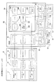
図1に示した成形品取出機は、いわゆる旋回型の一機種であって、成形機の固定盤61に載置固定された基部1と、基部1の上部に軸支された旋回部2と、旋回部2から金型60の開閉方向(Y軸方向)に延設された引抜アーム3と、引抜アーム3にスライド可能に取付けられて上下方向(Z軸方向)に延設された昇降アーム4と、昇降アーム4の下端に取付けられた成形品の取出ヘッド5とを備える。
(Configuration of molded product take-out machine)
The molded product take-out machine shown in FIG. 1 is one type of so-called swivel type, and includes a
なお、この成形品取出機は、図示しないが、その成形品取出動作を制御する動作制御部を備え、また、ティーチングや手動運転等の各種操作、各種情報表示等を可能とした操作コントローラがこの動作制御部と無線又は有線で通信接続されている。また、図1中の符号62は、成形機の可動盤である。
そして、上記成形品取出機は、駆動源としてそれ自体に位置検出器を持たないエアシリンダが使用されている。具体的には以下に説明する。
Although not shown, this molded product take-out machine includes an operation control unit that controls the molded product take-out operation, and an operation controller that enables various operations such as teaching and manual operation, and various information displays. The operation control unit is connected by wireless or wired communication. Moreover, the code |
The molded product take-out machine uses an air cylinder that does not have a position detector in itself as a drive source. Specifically, this will be described below.
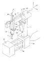
上記旋回部2には、この旋回部2をY軸まわりに旋回移動(X軸及びZ軸方向)させる駆動源としてエアシリンダからなる旋回用シリンダ20が連結されている。この旋回用シリンダ20は、シリンダチューブの下端が基部1に回動自在に取付けられ、ピストンロッド21が旋回部2に取付けられたステー22のガイド溝221に取り付けられている。従って、旋回用シリンダ20の作動により旋回部2が傾斜(X軸方向及びZ軸方向)して昇降アーム4を所定角度旋回させる。なお、上記ステー22のガイド溝221は、左右に長く形成されており、旋回用シリンダ20のピストンロッド21をこのガイド溝221の左端又は右端のいずれかに手動で寄せることで、旋回方向ならびに旋回角度の設定を行うことができ、旋回部2を左右のいずれかに傾斜させて昇降アーム4を左旋回又は右旋回させることができる。
The revolving
上記引抜アーム3には、昇降アーム4を引抜限と引抜戻り限との間で進退移動させる駆動源としてエアシリンダからなる引抜用シリンダ30が設けられている。この引抜用シリンダ30は、シリンダチューブの両端からロッドを突き出した両ロッドタイプであり、引抜アーム3上に露出した一方のロッドがピストンロッド31となって昇降アーム4のスライダ44に取り付けられている。従って、引抜用シリンダ30の作動により昇降アーム4のスライダ44が引抜アーム3上をスライドして昇降アーム4を引抜アーム3の長さ方向(Y軸方向)に沿って引抜限と引抜戻り限との間で進退移動させる。
また、引抜用シリンダ30の他方のロッドは、ガイドバー32となって旋回部2内に配置され、上記ピストンロッド31とは逆方向に進退移動する。そして、旋回部2内には、上記ガイドバー32の先端と対向したショックアブソーバ(緩衝機構)D2が設けられている。従って、引抜用シリンダ30のピストンロッド31が後退(引込)しガイドバー32が進出(突出)すると、ピストンロッド31の後退限近くでガイドバー32がショックアブソーバD2に当接し、ピストンロッド31が後退限に達するとガイドバー32によってピストンロッド31の後退移動が停止される。
The pulling arm 3 is provided with a pulling
The other rod of the
上記昇降アーム4には、下端の取出ヘッド5を下降限と上昇限との間で昇降移動させる駆動源としてエアシリンダからなる昇降用シリンダ40が設けられている。この昇降用シリンダ40は、シリンダチューブがスライダ44に固定され、ピストンロッド41に取出ヘッド5が取り付けられている。従って、昇降用シリンダ40の作動により取出ヘッド5を昇降アーム4の軸線方向(Z軸方向)に沿って下降限と上昇限との間で昇降移動させる。
また、昇降用シリンダ40のシリンダチューブ下部には、ガイド部材45が取付けられており、このガイド部材45には、ピストンロッド41に連結されたガイドバー42が挿通されるとともに、このガイドバー42の上方に設けたストッパ43と対向したショックアブソーバ(緩衝機構)D1が取付けられている。従って、昇降用シリンダ40のピストンロッド41の前進(突出)とともにガイドバー42が下降すると、ピストンロッド41の前進限近くでガイドバー42に設けたストッパ43がショックアブソーバD1に当接し、ピストンロッド41が前進限に到達すると上記ストッパ43によってピストンロッド41の前進移動が停止される。
なお、上記の各シリンダ20,30,40によって移動される、取出ヘッド5、昇降アーム4及び旋回部2等がこの成形品取出機の移動部位となる。
The elevating arm 4 is provided with an elevating
A
The take-out
(位置検出ユニットLS<加速度センサ利用>)
そして、上記成形品取出機の旋回部2には上記移動部位のストロークリミット(進み限、戻り限)への到達を検出するための加速度センサ71を搭載した位置検出ユニットLSが設けられている。上記加速度センサ71は、XYZ軸の3軸それぞれの振動を検出し、また、加速度センサ71自身の傾きを検出するものである。従って、各シリンダ20,30,40がストロークリミットで停止する際に振動が発生することから、上記位置検出ユニットLSは、その加速度センサ71で上記振動(加速度変化)を検出し、この検出信号から各シリンダ20,30,40のストロークリミットへの到達を認識する。また、旋回用シリンダ20が前進限へ到達すると水平姿勢の旋回部2が傾斜することから、上記位置検出ユニットLSは、その加速度センサ71で上記傾き(加速度変化)を検出し、この検出信号から旋回用シリンダ20のストロークリミットへの到達を認識する。
(Position detection unit LS <using acceleration sensor>)
The
上記位置検出ユニットLSは、図2に示すように、センサ部70と、処理部80とを有する。
センサ部70は、上記加速度センサ71の他に、ヒステリシスコンパレータ72及び出力ドライバ73を有する。加速度センサ71としては、例えば、圧電型の3軸加速度センサ(日立金属社製の品番「H48C」)が使用される。そして、この加速度センサ71で振動が検出されて出力される電気信号がヒステリシスコンパレータ72及び出力ドライバ73を通じて検出信号として処理部80に出力される。
一方、処理部80は、センサ部70の出力ドライバ73に対応した入力ドライバ81、後述する近接センサS1,S3に対応した入力ドライバ82、各シリンダ20,30,40のバルブ回路Vに電気接続された出力ドライバ83及びマイクロコンピュータ84を有する。そして、処理部80では、センサ部70から入力されたXYZ各軸での検出信号が各々の入力ドライバ81を通じてマイクロコンピュータ84に入力され、また、各近接センサS1,S3から入力された検出信号が各々の入力ドライバ82を通じてマイクロコンピュータ84に入力され、さらに、各シリンダ20,30,40のバルブ回路Vから出力されるバルブON信号が各々の出力ドライバ83を通じてマイクロコンピュータ84に入力される。
The position detection unit LS includes a
The
On the other hand, the
また、マイクロコンピュータ84は、I/O制御841、タイマ842、平均化処理部843、CPU844、RAM845、ROM846、フラッシュROM847等を有する。I/O制御841は、入力ドライバ81,82からの検出信号や出力ドライバ83からのバルブON信号を受けてCPU844に送る。タイマ842は、CPU844に対してバルブ回路VからのバルブON信号が入力されてからセンサ部70からの検出信号が入力されるまでの時間や、CPU844に対してバルブ回路VからのバルブON信号が入力されてから近接センサS1,S3からの検出信号が入力されるまでの時間の計測を行う。すなわち、このタイマ842で計測される時間は、上記各シリンダ20,30,40が作動しているシリンダ移動時間となる。平均化処理部843は、タイマ842により計測されたシリンダ移動時間を簡易平均化処理する。すなわち、上記シリンダ移動時間は小幅な範囲で毎回バラツキが生じ得るので、平均化処理部843によって今回計測されたシリンダ移動時間を前回測定時までの平均値と平均化してバラツキを平準化する。なお、このシリンダ移動時間が簡易平均化された平均化データは、そのシリンダ20,30,40の規定値又は実験値等による設定値の許容範囲内であれば、正常にストロークリミットへ到達したことが確認できる。RAM845には、通電時において上記平均化データ(すなわちシリンダ移動時間を簡易平均化処理したもの)が記憶され、そして、フラッシュROM847には、電源OFF時においてこの平均化データが記憶される。ROM846には、この処理部80における制御プログラム等を格納する。CPU844は、マイクロコンピュータ84内の上記各処理を制御する。
The
上記位置検出ユニットLSによって、集約的に以下の検出が可能となる。
(ア)取出ヘッド5の下降限又は上昇限への到達を認識できる。すなわち、位置検出ユニットLSによって、取出ヘッド5を移動させる昇降用シリンダ40がストロークリミットに達したときに生じる振動を検出し、これにより、昇降用シリンダ40のピストンロッド41の前進限又は後退限への到達を認識できるからである。
また、昇降用シリンダ40のピストンロッド41が前進限で停止する時は、前進限近くでガイドバー42のストッパ43がショックアブソーバD1に当接しこのショックアブソーバD1で緩衝させながら停止するので、上記位置検出ユニットLSは、このガイドバー42のストッパ43がショックアブソーバD1に当接したときに生じる振動を検出して、取出ヘッド5が下降移動する時には、まもなく下降限へ達することも把握できる。
なお、取出ヘッド5の上昇限側にはショックアブソーバD1を備えないので、取出ヘッド5の下降限、上昇限への到達を区別して認識することも可能である。
The position detection unit LS enables the following detection collectively.
(A) Recognizing that the take-out
Further, when the
Since the shock absorber D1 is not provided on the ascending limit side of the take-out
(イ)昇降アーム4の引抜限又は引抜戻り限への到達を認識できる。すなわち、位置検出ユニットLSによって、引抜用シリンダ30がストロークリミットに達したときに生じる振動を検出し、これにより、引抜用シリンダ30のピストンロッド31の前進限又は後退限への到達を認識できるからである。
また、引抜用シリンダ30のピストンロッド31が後退限で停止する時は、後退限近くで反対側のガイドバー32がショックアブソーバD2に当接しこのショックアブソーバD2で緩衝させながら停止するので、上記位置検出ユニットLSは、このガイドバー32がショックアブソーバD2に当接したときに生じる振動を検出して、昇降アーム4が引抜戻り側(ピストンロッド31の後退側)へ移動する時には、まもなく引抜戻り限へ達することも認識できる。
なお、昇降アーム4の前進限側にはショックアブソーバD2を備えないので、昇降アーム4の引抜限、引抜戻り限への到達を区別して認識することも可能である。
(A) Recognizing that the lifting arm 4 has reached the drawing limit or drawing return limit. That is, the position detection unit LS detects vibrations that occur when the
When the
In addition, since the shock absorber D2 is not provided on the forward limit side of the lifting arm 4, it is possible to distinguish and recognize whether the lifting arm 4 has reached the withdrawal limit or the withdrawal return limit.
(ウ)旋回部2の旋回限又は旋回戻り限への到達(昇降アーム4の旋回限又は旋回戻り限への到達)を認識できる。すなわち、位置検出ユニットLSによって、旋回用シリンダ20がストロークリミットに達することでの旋回部2の傾きを検出できるからである。
以上のように、上記位置検出ユニットLSによれば、各シリンダの前進限及び後退限への到達を集約的に検出し把握することができる。従って、必ずしも、従来のように各シリンダの前進限位置及び後退限位置の両方に近接センサ(リミットセンサ)を配置して検出する必要がない。
(C) Reaching the turning limit or turning return limit of the turning unit 2 (reaching the turning limit or turning return limit of the elevating arm 4) can be recognized. That is, the position detection unit LS can detect the inclination of the
As described above, according to the position detection unit LS, it is possible to collectively detect and grasp the arrival of each cylinder at the forward limit and the backward limit. Therefore, it is not always necessary to place and detect proximity sensors (limit sensors) at both the forward limit position and the backward limit position of each cylinder as in the prior art.
(近接センサ)
一方、上記位置検出ユニットLSによる振動検出だけでは、初期状態においてシリンダの前進限へのストロークリミット到達状態なのか、後退限へのストロークリミット到達状態なのかを区別して把握するのは困難な場合がある。例えば、電源切断時あるいは電源投入時には、必ず、各シリンダを一方側へのストロークリミット状態とするリセット動作を行うこととすれば、このリセットを基準にして上記位置検出ユニットLSだけで、引抜用シリンダ30及び昇降用シリンダ40が前進限、後退限のいずれのストロークリミット到達状態か確実に把握できる。ところが、このようなリセット動作を行わないような場合、電源投入時にこれら引抜用シリンダ30及び昇降用シリンダ40がいずれのストロークリミット状態にあるのかを認識できない。
そこで、上記成形品取出機にあっては、引抜用シリンダ30側には、その前進限のストロークリミットを検出するリミットセンサとして近接センサS3が設けられ、また、昇降用シリンダ40側には、その上昇限のストロークリミットを検出するリミットセンサとして近接センサS1が設けられている(図1参照)。
(Proximity sensor)
On the other hand, it may be difficult to distinguish and grasp whether the stroke limit has reached the forward limit of the cylinder or the stroke limit has reached the reverse limit in the initial state only by detecting the vibration by the position detection unit LS. is there. For example, when the power is turned off or the power is turned on, if a reset operation is always performed in which each cylinder is in a stroke limit state to one side, the cylinder for pulling out can be performed only by the position detection unit LS based on this reset. Thus, it can be ascertained whether the stroke limit reaching the forward limit or the reverse limit is reached. However, when such a reset operation is not performed, it is not possible to recognize which stroke limit state the drawing
Therefore, in the molded product take-out machine, a proximity sensor S3 is provided on the
すなわち、旋回部2内において、引抜用シリンダ30のガイドバー32が後退限に達するとこのガイドバー32の先端に設けたドグ9を感知する位置に近接センサS3が配置され(図1参照)、この近接センサS3によって引抜用シリンダ30のピストンロッド31が前進限にあるのか否かを認識するようにしている。
また、昇降アーム4のガイド部材45において、昇降用シリンダ40のピストンロッド41が後退限に達するとこのピストンロッド41(あるいは取出ヘッド5の上部)に設けたドグ(図示せず)を感知する位置に近接センサS1が配置され(図1参照)、この近接センサS1によって昇降用シリンダ40のピストンロッド41が後退限にあるのか否かを認識するようにしている。
That is, when the
Further, in the
従って、これら近接センサS1,S3によって、電源投入時には引抜用シリンダ30及び昇降用シリンダ40のストロークリミット状態を確実に認識することができる。例えば、電源投入時に、引抜用シリンダ30側の近接センサS3が未検知状態であれば、引抜用シリンダ30は後退限状態にあると把握でき、また、昇降用シリンダ40側の近接センサS1が検知状態であれば、昇降用シリンダ40は後退限状態にあると把握できることとなる。
このように、上記各近接センサS1,S3は、成形品取出機の初期状態を認識するために使用される。但し、上記各近接センサS1,S3を、従来のように成形品取出機の成形品取出動作のタイミング制御のために使用してもよい。
Therefore, the proximity sensors S1 and S3 can reliably recognize the stroke limit states of the
As described above, the proximity sensors S1 and S3 are used to recognize the initial state of the molded product take-out machine. However, each of the proximity sensors S1 and S3 may be used for timing control of the molded product take-out operation of the molded product take-out machine as in the prior art.
(成形品取出機の動作)
次に、上記成形品取出機の成形品取出動作を説明する。
なお、この成形品取出動作は、成形品取出機に備える動作制御部(図示せず)からの動作指令に基づいて行われる。また、この成形品取出機の初期状態は、上述のとおり、2つの近接センサS1,S3から認識できる。そして、この成形品取出機の初期状態が、昇降アーム4が引抜戻り限にあり、取出ヘッド5が上昇限にある(取出ヘッド5の待機位置)として、以下の説明をする。
(Operation of molded product take-out machine)
Next, the molded product removal operation of the molded product take-out machine will be described.
This molded product take-out operation is performed based on an operation command from an operation control unit (not shown) provided in the molded product take-out machine. Further, the initial state of the molded product take-out machine can be recognized from the two proximity sensors S1 and S3 as described above. The initial state of the molded product take-out machine will be described below assuming that the lifting arm 4 is at the withdrawal return limit and the take-out
まず、成形機の金型60が型開きすると、昇降用シリンダ40を作動させてそのピストンロッド41を前進移動させ、取出ヘッド5を金型60上方の待機位置から下降させて金型60内に進入させる。このとき、ガイドバー42が同時に下降するので、位置検出ユニットLSは、ガイドバー42のストッパ43がショックアブソーバD1に当接したときの振動を検出し、これにより、取出ヘッド5がまもなく下降限へ達することを認識する。従って、位置検出ユニットLSのこのときの振動検出により、動作制御部は、次の動作指令(引抜用シリンダ30の作動指令)を行う。これにより、次の動作が速やかに行われるので、取出動作全体のサイクルタイムの短縮を図ることができる。次いで、位置検出ユニットLSは、昇降用シリンダ40のピストンロッド41が前進限へ到達したときの振動(ガイドバー42のストッパ43がショックアブソーバD1を押し込んで停止する際の振動も含む。)を検出し、これにより、取出ヘッド5の下降限到達を認識する。
First, when the
取出ヘッド5の下降が完了するか、この下降完了直前に、速やかに引抜用シリンダ30が作動してそのピストンロッド31を前進移動させ、取出ヘッド5を引抜限まで移動して可動盤62側の金型60に接近させる。このとき、位置検出ユニットLSは、引抜用シリンダ30のピストンロッド31が前進限へ到達したときの振動を検出し、これにより、取出ヘッド5の引抜限到達を認識する。従って、位置検出ユニットLSのこのときの振動検出により、動作制御部は、次の動作指令(取出ヘッド5による成形品把持)を行う。なお、このとき、ガイドバー32がピストンロッド31と同時に引込移動し、このガイドバー32のドグ9を近接センサS3が感知することで、取出ヘッド5の引抜限到達を認識することもできる。
Immediately before the lowering of the take-out
そして、取出ヘッド5がこの引抜限に到達すると、取出ヘッド5に成形品を把持させる。取出ヘッド5による成形品把持の待ち時間がタイマーアップすると、引抜用シリンダ30を作動させてそのピストンロッド31を後退移動させ、取出ヘッド5を引抜戻り限まで移動して可動盤62側の金型60から離間させる。このとき、ガイドバー32が同時に突出移動するので、位置検出ユニットLSは、ガイドバー32がショックアブソーバD2に当接したときの振動を検出し、これにより、取出ヘッド5がまもなく引抜戻り限へ達することを認識する。従って、位置検出ユニットLSのこのときの振動検出により、動作制御部は、次の動作指令(昇降用シリンダ40の作動指令)を行う。これにより、次の動作が速やかに行われるので、取出動作全体のサイクルタイムの短縮を図ることができる。次いで、位置検出ユニットLSは、引抜用シリンダ30のピストンロッド31が後退限へ到達したときの振動(ガイドバー32がショックアブソーバD2を押し込んで停止する際の振動も含む。)を検出し、これにより、取出ヘッド5の引抜戻り限到達を認識する。
When the take-out
取出ヘッド5が引抜戻り限に到達するか、この引抜戻り限到達直前に、速やかに昇降用シリンダ40が作動してそのピストンロッド41を後退移動させ、取出ヘッド5を上昇させる。このとき、位置検出ユニットLSは、昇降用シリンダ40のピストンロッド41が後退限へ到達したときの振動を検出し、これにより、取出ヘッド5の上昇限到達を認識する。従って、位置検出ユニットLSのこのときの振動検出により、動作制御部は、次の動作指令(旋回用シリンダ20の作動指令)を行う。なお、このとき、ピストンロッド41に設けたドグ(図示せず)を近接センサS1が感知することで、取出ヘッド5の上昇限到達を認識することもできる。
Immediately before the
取出ヘッド5が上昇限に到達すると、次の動作として旋回用シリンダ20を作動させてそのピストンロッド21を前進限まで移動し旋回部2を傾斜させ、引抜アーム3とともに昇降アーム4を所定角度旋回させる。このとき、位置検出ユニットLSは、旋回部2の傾斜によってこの位置検出ユニットLS自身が傾くことによる加速度変化を検出し、これにより昇降アーム4等の旋回限到達を認識する。
When the take-out
昇降アーム4等の旋回が完了すると、再び昇降用シリンダ40を作動させてそのピストンロッド41を前進移動させて取出ヘッド5を下降させた後、取出ヘッド5による成形品の把持を解除して成形品を回収させ、その後、昇降用シリンダ40を作動させてそのピストンロッド41を後退移動させ、取出ヘッド5を上昇復帰させる。このときも、上記同様に、位置検出ユニットLSによって昇降アーム4における振動検出により取出ヘッド5の下降限と上昇限への到達を認識し、また、取出ヘッド5の上昇時は、近接センサS1によっても昇降用シリンダ40のピストンロッド41のドグ感知により取出ヘッド5の上昇限到達を認識することもできる。
When the pivoting of the lifting arm 4 or the like is completed, the lifting
次いで、旋回用シリンダ20を作動させてそのピストンロッド21を後退限まで移動し旋回部2を水平にさせ、引抜アーム3及び昇降アーム4を逆旋回する。すると、取出ヘッド5が元の待機位置に復帰する。このときも、上記同様に、位置検出ユニットLSは、旋回部2が水平姿勢となってこの位置検出ユニットLS自身が水平となったことによる加速度変化を検出し、これにより、昇降アーム4等の旋回戻り限到達を認識する。
以上のようにして、この成形品取出機の取出動作の1サイクルが完了する。
Next, the turning
As described above, one cycle of the take-out operation of the molded product take-out machine is completed.
(異常検出ルーチン)
一方、位置検出ユニットLSは、上記取出動作においてシリンダ異常が発生していないか常時監視するための異常検出ルーチンを実行している。
(1)まず、昇降用シリンダ40及び引抜用シリンダ30に対して、以下(A)(B)の2通りの異常検出ルーチンが実行される。
(Abnormality detection routine)
On the other hand, the position detection unit LS executes an abnormality detection routine for constantly monitoring whether or not a cylinder abnormality has occurred in the take-out operation.
(1) First, the following two types of abnormality detection routines (A) and (B) are executed for the lifting
(A)近接センサの無側→有側
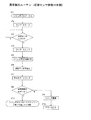
以下、シリンダのピストンロッドが近接センサの無側から有側へ移動するときのルーチンを説明するが、このルーチンは、昇降用シリンダ40のピストンロッド41が前進限(近接センサS1無側)から後退限(近接センサS1有側)へ移動するときと、引抜用シリンダ30のピストンロッド31が後退限(近接センサS3無側)から前進限(近接センサS3有側)へ移動するときに、常時実行される。なお、以下の図3を参照した説明で、「シリンダ」とは引抜用シリンダ30又は昇降用シリンダ40を指す。
(A) Non-proximal side of proximity sensor → existing side Hereinafter, a routine when the piston rod of the cylinder moves from the non-side of the proximity sensor to the side of the proximity sensor will be described. When moving from the forward limit (without proximity sensor S1) to the backward limit (with proximity sensor S1), the
図3を参照して、シリンダを駆動するバルブON信号が処理部80のCPU844に入力されると、タイマ842をスタートする(ST1,ST2)。そして、近接センサでピストンロッドのストロークリミット到達が感知され(ST3)、この近接センサの検出信号が処理部80のCPU844に入力されると、タイマ842を停止し(ST4)、シリンダ移動時間が計測される(ST5)。すると、このシリンダ移動時間の測定データは、平均化処理部843で平均化され(ST6)、そして、平均化データとしてRAM845に一旦記憶される(ST7)。
Referring to FIG. 3, when a valve ON signal for driving the cylinder is input to
次に、この平均化データが、このシリンダの規格値あるいは実験値等で予め規定されるシリンダ移動時間の設定値の許容範囲内にあるか否か判断する(ST8)。このとき、平均化データが設定値の許容範囲から逸脱する場合は、このシリンダへのエア元圧の変更やシリンダの移動速度が変更された等のシリンダ異常と判断し(ST9)、アラーム出力等の所定の報知が行われる(ST10)。なお、この場合、シリンダには何ら異常がなく近接センサ側の故障やセンサ線の断線等、あるいはシリンダ及びセンサの両方の異常であることも考え得るので、上記報知は、センサ異常をも考慮した形態であってもよい。
一方、平均化データが設定値の許容範囲内にある場合は、シリンダ異常がなく正常にストロークリミットへ到達したと判断する(ST11)。
このようにして、仮に近接センサでシリンダのストロークリミットを検出する場合でも、近接センサでの検出を捕捉することで、シリンダのストロークリミット到達の判断を正確に行える。しかも、シリンダ異常(あるいは近接センサ異常も含む異常)も同時に検出することができる。
Next, it is determined whether or not the averaged data is within an allowable range of a set value of the cylinder movement time that is defined in advance by a standard value or an experimental value of the cylinder (ST8). At this time, if the averaged data deviates from the allowable range of the set value, it is determined that there is a cylinder abnormality such as a change in the air source pressure to the cylinder or a change in the cylinder moving speed (ST9), and an alarm output or the like. Is notified (ST10). In this case, there is no abnormality in the cylinder, and it may be considered that there is a failure on the proximity sensor side, disconnection of the sensor wire, etc., or abnormality of both the cylinder and the sensor, so the above notification also considers sensor abnormality Form may be sufficient.
On the other hand, if the averaged data is within the allowable range of the set value, it is determined that there is no cylinder abnormality and the stroke limit is normally reached (ST11).
Thus, even when the proximity sensor detects the cylinder stroke limit, the detection of the cylinder stroke limit can be accurately determined by capturing the detection by the proximity sensor. In addition, cylinder abnormalities (or abnormalities including proximity sensor abnormalities) can be detected simultaneously.
(B)近接センサ有側→無側のルーチン
以下、シリンダのピストンロッドが近接センサの有側から無側へ移動するときのルーチンを説明するが、このルーチンは、昇降用シリンダ40のピストンロッド41が後退限(近接センサS1有側)から前進限(近接センサS1無側)へ移動するときと、引抜用シリンダ30のピストンロッド31が前進限(近接センサS3有側)から後退限(近接センサS3無側)へ移動するときに、常時実行される。なお、以下の図4を参照した説明で、「シリンダ」とは引抜用シリンダ30又は昇降用シリンダ40を指す。
(B) Routine with proximity sensor → Routine with no proximity sensor Hereinafter, a routine when the piston rod of the cylinder moves from the proximity side to the proximity side of the proximity sensor will be described. This routine includes the
図4を参照して、シリンダを駆動するバルブON信号が処理部80のCPU844に入力されると、タイマ842をスタートする(ST21,ST22)。このとき、シリンダは、近接センサの有側から無側へ駆動されるので、設定時間内に近接センサが入力OFF、すなわち近接センサが未検知状態とならない場合は(ST23で「NO」)、シリンダ異常(あるいは上記同様に近接センサ異常も含む異常)と判断し(ST24)、アラーム出力等の所定の報知が行われる(ST25)。
Referring to FIG. 4, when a valve ON signal for driving the cylinder is input to
次に、センサ部70の加速度センサ71で振動が検出され(ST26)、このセンサ部70での検出信号が処理部80のCPU844に入力されると、タイマ842におけるシリンダ移動時間が計測される(ST27)。すると、このシリンダ移動時間の測定データは、平均化処理部で平均化され(ST28)、平均化データとしてRAM845に一旦記憶される(ST29)。
Next, vibration is detected by the
そして、この平均化データが、このシリンダの規格値あるいは実験値等で予め規定されるシリンダ移動時間の設定値の許容範囲内にあるか否か判断する(ST30)。このとき、平均化データが設定値の許容範囲以下である場合、加速度センサ71で検出した振動は、外乱による振動であったと判断し、処理をステップST26に戻し、再びセンサ部70での振動検出を待つ。従って、この処理は、外乱無効化処理となる。
すなわち、引抜用シリンダ30や昇降用シリンダ40のストロークリミットをセンサ部70の加速度センサ71の振動検出で検出するため、加速度センサ71が外部からの振動(外乱)を受けた場合にストロークリミットを誤検出するおそれがある。ところが、上記外乱無効化処理によって、外乱をキャンセルすることができ、これにより、シリンダのストロークリミットを確実に検出することができる。なお、平均化データが、シリンダ移動時間の設定値の許容範囲以下であれば、何度外乱が入っても上記外乱無効化処理される。
Then, it is determined whether or not the averaged data is within an allowable range of a set value of the cylinder movement time that is defined in advance by a standard value or an experimental value of the cylinder (ST30). At this time, if the averaged data is equal to or smaller than the allowable range of the set value, it is determined that the vibration detected by the
That is, since the stroke limit of the pulling
一方、平均化データが設定値の許容範囲内にある場合は、タイマ842を停止し(ST33)、シリンダがストロークリミットへ正常に到達した判断する(ST34)。
なお、平均化データが設定値の許容範囲以上であった場合は、このシリンダへのエア元圧の変更やシリンダの移動速度が変更された等と判断し(ST31)、アラーム出力等の所定の報知が行われる(ST32)。この場合の報知も、上記同様に加速度センサ71の異常をも考慮した形態であってもよい。
このようにして、加速度センサ71の検出を捕捉することで、外乱を除外し、シリンダのストロークリミット到達の判断を正確に行える。しかも、シリンダ異常(あるいは上記同様に加速度センサ71異常も含む異常)も同時に検出することができる。
On the other hand, if the averaged data is within the allowable range of the set value, the
If the averaged data is equal to or larger than the allowable range of the set value, it is determined that the air source pressure is changed to the cylinder or the moving speed of the cylinder is changed (ST31), and a predetermined alarm output or the like is determined. Notification is performed (ST32). The notification in this case may be in a form that also considers the abnormality of the
In this way, by capturing the detection of the
(2)次に、旋回用シリンダ20に対しては、図4のフローチャートにおいて、ステップST23〜ST25までを無くし、且つステップST26の「振動検出?」を「傾き(水平)検出?」とするルーチンとし、このルーチンを旋回用シリンダ20の前進限及び後退限へ移動するときに常時実行する。なお、このルーチンの内容は、初期動作時のシリンダ異常検出を行わないこと、加速度センサ71で傾きあるいは水平を検出することの他は、上述した図4のものと共通した内容である。従って、このルーチンの実行により、上記同様に、旋回用シリンダ20のストロークリミット到達の判断を正確に行え、且つ旋回用シリンダ20異常(加速度センサ71異常を含めてもよい。)も検出可能となる。
(2) Next, for the turning
以上のように、上記実施の形態における成形品取出機によれば、駆動源としてそれ自体に位置検出器を持たないエアシリンダが用いられる場合でも、集約検出型の上記位置検出ユニットLSによって、取出ヘッド5や昇降アーム4等の移動部位が停止する際の振動による加速度変化、他の移動部位となる旋回部2の傾きによる加速度変化を検出することで、これら移動部位の進み限又は戻り限への到達を集約的に認識することができる。その結果、従来、移動部位の進み限、戻り限のそれぞれを直接的に検出していた6個のリミットセンサ(近接センサLS1〜LS4、リミットスイッチLS5,LS6)のうち、4個削減することができる。また、これに伴って、リミットセンサのセンサ配線も減少し断線等の可能性が低くなり位置検出の信頼性を向上することができ、さらに、リミットセンサやそのメカ部品の減少で成形品取出機の製作や部品交換の時の工数、コスト等を大幅に削減することができる。
As described above, according to the molded product take-out machine in the above-described embodiment, even when an air cylinder that does not have a position detector is used as a drive source, the take-off is performed by the position detection unit LS of the collective detection type. By detecting an acceleration change due to vibration when the moving part such as the
また、昇降アーム4において取出ヘッド5の下降限位置と、旋回部2において昇降アーム4の引抜戻り限位置とには、緩衝機構としてのショックアブソーバD1,D2がそれぞれ設けられており、それら移動部位の移動停止直前においてショックアブソーバD1,D2への当接による振動が、上記位置検出ユニットLSによって検出される。これにより、取出ヘッド5が下降移動する時には、まもなく下降限へ達することが認識でき、また、昇降アーム4が引抜戻り側へ移動する時には、まもなく引抜戻り限へ達することが認識できるので、次の動作指令を素早く行うことができる。従って、次の動作が速やかに行われ、取出動作全体のサイクルタイムの短縮を図ることができ、ひいては成形作業の効率を向上することができる。
Further, shock absorbers D1 and D2 as shock absorbing mechanisms are respectively provided at the lower limit position of the take-out
一方、上記位置検出ユニットLSでは、振動検出に際して移動部位のストロークリミット到達による振動以外の振動による外乱を受けた場合でも、上記外乱無効化処理(図4中のST30→ST26)によってこの外乱を無効化する。従って、加速度センサ71を搭載して振動検出を行う上記位置検出ユニットLSであっても、移動部位のストロークリミット到達を正しく認識でき、位置検出の信頼性を確保することができる。
On the other hand, in the position detection unit LS, even when a disturbance due to vibration other than the vibration due to reaching the stroke limit of the moving part is detected during vibration detection, the disturbance is invalidated by the disturbance invalidation processing (ST30 → ST26 in FIG. 4). Turn into. Therefore, even if the position detection unit LS is equipped with the
(その他)
本発明は、上記実施の形態のみに限定されず、例えば、以下のような変更も可能である。
(1)上記成形品取出機に設けた各近接センサS1,S3は、昇降用シリンダ40の後退限到達や引抜用シリンダ30の前進限到達を検出可能とするものの、主に昇降アーム4と引抜アーム3における初期位置を認識するためのものであるから、上述のようにリセット動作等によって移動部位の初期位置を認識する初期位置認識手段を設けてこれらの近接センサS1,S3も削減し、すべての移動部位のストロークリミット到達を加速度センサ71搭載の上記位置検出ユニットLSだけで行うようにしてもよい。
これにより、近接センサをすべて無くすことができ、また、近接センサの設置に伴った不利益(センサ配線断線の可能性増、工数・コストの上昇等)を完全に無くすことができる。
(2)緩衝機構は、上記ショックアブソーバD1,D2として昇降アーム4の下降限と引抜アーム3の引抜戻り限との対応位置にそれぞれ設けるが、これに限らず、移動部位における進み限、戻り限の一方又は両方の対応位置に設けてもよく、また、このような緩衝機構を何ら設けないようにしてもよい。
(3)各シリンダ20,30,40のピストンロッド21,31,41における前進限及び後退限と、取出ヘッド5やアーム3,4、旋回部2等の移動部位における進み限及び戻り限との対応関係は、図1に示す成形品取出機のような対応関係に限らず、図1に示す成形品取出機とはその一部又は全部が逆方向となる対応関係になる等、適宜に設定してもよい。
(4)移動部位の駆動源としては、上記エアシリンダに限らず、駆動源自体に位置検出器を持たない油圧シリンダ、サーボモータ以外の伝動モータ等でもよい。
(5)本発明に係る位置検出装置としての上記位置検出ユニットLSを設けた成形品取出機としては、上記旋回型に限らず、トラバース型、サイドエントリー型、その他の成形品取出機であってもよい。
(6)本発明に係る位置検出装置は、駆動源により一定範囲を往復移動させる移動部位を有するものであれば、成形品取出機に限らず、各種の産業ロボットや搬送装置等に設けてもよい。
(Other)
The present invention is not limited to the above embodiment, and for example, the following modifications can be made.
(1) Although the proximity sensors S1 and S3 provided in the molded product take-out machine can detect whether the elevating
As a result, all proximity sensors can be eliminated, and the disadvantages associated with the installation of proximity sensors (increased possibility of disconnection of sensor wiring, increase in man-hours and costs, etc.) can be completely eliminated.
(2) The shock absorbers D1 and D2 are provided at the corresponding positions of the lowering limit of the lifting arm 4 and the pulling return limit of the pulling arm 3 as the shock absorbers D1 and D2. May be provided at one or both of the corresponding positions, and no such buffering mechanism may be provided.
(3) The forward limit and the backward limit of the
(4) The drive source of the moving part is not limited to the air cylinder, but may be a hydraulic cylinder having no position detector in the drive source itself, a transmission motor other than the servo motor, or the like.
(5) The molded product take-out machine provided with the position detection unit LS as the position detection device according to the present invention is not limited to the swivel type, but is a traverse type, a side entry type, and other molded product take-out machines. Also good.
(6) The position detection device according to the present invention is not limited to a molded product take-out machine as long as it has a moving part that reciprocates within a certain range by a drive source, and may be provided in various industrial robots, conveyance devices, and the like. Good.
1 基部
2 旋回部
3 引抜アーム
4 昇降アーム
5 取出ヘッド
20 旋回用シリンダ(駆動源)
21,31,41 ピストンロッド
30 引抜用シリンダ(駆動源)
32,42 ガイドバー
40 昇降用シリンダ(駆動源)
45 ガイド部材
60 金型
70 センサ部
71 加速度センサ
80 処理部
D1,D2 ショックアブソーバ(緩衝機構)
LS 位置検出ユニット(位置検出装置)
S1,S2 近接センサ
DESCRIPTION OF
21, 31, 41
32, 42
45
LS position detection unit (position detection device)
S1, S2 Proximity sensor
Claims (5)
上記移動部位の停止を停止直前に緩衝させる緩衝機構を設けたことを特徴とする位置検出装置。 The position detection device according to claim 1,
A position detection device provided with a buffer mechanism for buffering the stop of the moving part immediately before the stop.
上記駆動源による移動時間の設定範囲までに検出された振動を移動部位の停止の際の振動以外の外乱として無効化する処理部を設けたことを特徴とする位置検出装置。 In the position detection device according to claim 1 or 2,
A position detection apparatus comprising: a processing unit that invalidates vibration detected up to a moving time set range by the drive source as disturbance other than vibration when the moving part is stopped.
XYZ軸の各軸ごとに移動部位が停止する際の振動又は傾きによる加速度変化を検出可能とする1つの集約型センサを設けたことを特徴とする位置検出装置。 The position detection device according to any one of claims 1 to 3,
A position detecting apparatus comprising a single integrated sensor capable of detecting an acceleration change due to vibration or inclination when a moving part stops for each of the XYZ axes.
上記移動部位が停止する際の振動又は傾きによる加速度変化を検出するセンサ部と、
上記センサ部の検出信号に基づいて上記移動部位の進み限又は戻り限への到達を判断する処理部とを備え、
本位置検出装置は、成形機の金型から成形品を取り出す取出ヘッドと、XYZ軸のいずれか又はすべての方向に向けて延設するアームと、上記取出ヘッド又は上記所定のアーム等で構成する移動部位を一定範囲に往復移動させる駆動源とを備える成形品取出機に設けられていることを特徴とする位置検出装置。
The position detection device according to any one of claims 1 to 4,
A sensor unit for detecting an acceleration change due to vibration or tilt when the moving part stops;
A processing unit for determining whether the moving part has reached an advance limit or a return limit based on a detection signal of the sensor unit;
This position detection device includes a takeout head that takes out a molded product from a mold of a molding machine, an arm that extends in any or all directions of the XYZ axes, the takeout head, the predetermined arm, or the like. A position detection device provided in a molded product take-out machine including a drive source that reciprocates a moving part within a certain range.
Priority Applications (1)
| Application Number | Priority Date | Filing Date | Title |
|---|---|---|---|
| JP2005343802A JP2007144580A (en) | 2005-11-29 | 2005-11-29 | Position detection device |
Applications Claiming Priority (1)
| Application Number | Priority Date | Filing Date | Title |
|---|---|---|---|
| JP2005343802A JP2007144580A (en) | 2005-11-29 | 2005-11-29 | Position detection device |
Publications (1)
| Publication Number | Publication Date |
|---|---|
| JP2007144580A true JP2007144580A (en) | 2007-06-14 |
Family
ID=38206590
Family Applications (1)
| Application Number | Title | Priority Date | Filing Date |
|---|---|---|---|
| JP2005343802A Pending JP2007144580A (en) | 2005-11-29 | 2005-11-29 | Position detection device |
Country Status (1)
| Country | Link |
|---|---|
| JP (1) | JP2007144580A (en) |
Cited By (5)
| Publication number | Priority date | Publication date | Assignee | Title |
|---|---|---|---|---|
| CN103543784A (en) * | 2013-11-12 | 2014-01-29 | 上海嘉耐真空设备有限公司 | One-armed controllable limiting cylinder fixing mechanism |
| JP2016078407A (en) * | 2014-10-22 | 2016-05-16 | 株式会社ユーシン精機 | Molding take-out machine |
| WO2018114531A1 (en) * | 2016-12-19 | 2018-06-28 | Robert Bosch Gmbh | Method and device for determining a position oof an actuating element |
| CN115095578A (en) * | 2022-08-24 | 2022-09-23 | 江苏兰格特自动化设备有限公司 | Pneumatic actuator with buffer structure |
| WO2023002519A1 (en) * | 2021-07-19 | 2023-01-26 | 株式会社バルカー | Liquid pressure apparatus monitoring system |
-
2005
- 2005-11-29 JP JP2005343802A patent/JP2007144580A/en active Pending
Cited By (10)
| Publication number | Priority date | Publication date | Assignee | Title |
|---|---|---|---|---|
| CN103543784A (en) * | 2013-11-12 | 2014-01-29 | 上海嘉耐真空设备有限公司 | One-armed controllable limiting cylinder fixing mechanism |
| CN103543784B (en) * | 2013-11-12 | 2016-04-06 | 上海嘉耐真空设备有限公司 | The controlled limiting cylinder fixed mechanism of single arm type |
| JP2016078407A (en) * | 2014-10-22 | 2016-05-16 | 株式会社ユーシン精機 | Molding take-out machine |
| WO2018114531A1 (en) * | 2016-12-19 | 2018-06-28 | Robert Bosch Gmbh | Method and device for determining a position oof an actuating element |
| CN110062874A (en) * | 2016-12-19 | 2019-07-26 | 罗伯特·博世有限公司 | Method and apparatus for determining the position of regulating element |
| US10800237B2 (en) | 2016-12-19 | 2020-10-13 | Robert Bosch Gmbh | Method and device for determining a position of an actuating element |
| CN110062874B (en) * | 2016-12-19 | 2022-01-18 | 罗伯特·博世有限公司 | Method and device for determining the position of an adjusting element |
| WO2023002519A1 (en) * | 2021-07-19 | 2023-01-26 | 株式会社バルカー | Liquid pressure apparatus monitoring system |
| CN115095578A (en) * | 2022-08-24 | 2022-09-23 | 江苏兰格特自动化设备有限公司 | Pneumatic actuator with buffer structure |
| CN115095578B (en) * | 2022-08-24 | 2023-02-03 | 江苏兰格特自动化设备有限公司 | Pneumatic actuating device with buffer structure |
Similar Documents
| Publication | Publication Date | Title |
|---|---|---|
| JP2007144580A (en) | Position detection device | |
| US9475200B2 (en) | Safety device for a handling apparatus, in particular an industrial robot, and method for operating the safety device | |
| JP4477546B2 (en) | Molding condition setting method | |
| US20170113349A1 (en) | Safety monitoring device for robot | |
| CN107914305B (en) | Cutting method and cutting system | |
| JP2010137299A5 (en) | ||
| CN206803983U (en) | Robot point inspection mistake proofing probe | |
| JP4731208B2 (en) | Mold take-out machine | |
| CN108545016A (en) | A kind of industrial intelligent robot carried for workshop based on Internet of Things | |
| CN106426744A (en) | Forming machine for door and window accessories and use method thereof | |
| CN106956257B (en) | Manipulator | |
| CN107462436A (en) | A kind of solution ion concentration detects machine sampling manipulator | |
| CN212352089U (en) | Two-stage stretching manipulator | |
| JP5162959B2 (en) | In-furnace workpiece extraction device for heat treatment furnace | |
| CN209615485U (en) | A kind of radio patrol checking machine people's system | |
| JP2011124411A (en) | Method and apparatus for mounting electronic component | |
| CN219337501U (en) | Positioning device for plastic hollow cavity | |
| JP4214813B2 (en) | Unmanned forklift | |
| JP2004042096A (en) | Bending device | |
| CN217032442U (en) | Automatic leveling mechanism for 3D printer platform detection | |
| CN211043998U (en) | Aluminum bar manipulator servo control system | |
| KR940003004Y1 (en) | Simple robot hand joint | |
| KR20170000856A (en) | Apparatus for moving a slab and method thereof | |
| CN112589803B (en) | Control method and device of mechanical arm and mechanical arm equipment | |
| JP2882067B2 (en) | Robot for press |