JP2007141663A - Non-diffitype connector retaining structure - Google Patents
Non-diffitype connector retaining structure Download PDFInfo
- Publication number
- JP2007141663A JP2007141663A JP2005334091A JP2005334091A JP2007141663A JP 2007141663 A JP2007141663 A JP 2007141663A JP 2005334091 A JP2005334091 A JP 2005334091A JP 2005334091 A JP2005334091 A JP 2005334091A JP 2007141663 A JP2007141663 A JP 2007141663A
- Authority
- JP
- Japan
- Prior art keywords
- reinforcing plate
- connector
- board
- flexible board
- substrate
- Prior art date
- Legal status (The legal status is an assumption and is not a legal conclusion. Google has not performed a legal analysis and makes no representation as to the accuracy of the status listed.)
- Pending
Links
Images
Landscapes
- Coupling Device And Connection With Printed Circuit (AREA)
Abstract
【課題】補強板付きフレキシブル基板が挿抜されるノンジフ式コネクタの抜止構造であって、同基板の確実な抜止めと、スムーズな抜去とを両立させ、既存の補強板付きフレキシブル基板をそのまま採用することができるノンジフ式コネクタの抜止構造を提供する。
【解決手段】フレキシブルな基板本体21の先端部の一面に可撓性を有する補強板22を全面的に固着して構成された補強板付きフレキシブル基板20が挿抜されるノンジフ式コネクタ10の抜止構造であって、コネクタハウジング30に、補強板付きフレキシブル基板20を挿抜するための細長い開口部31を形成し、ハウジング30に、開口部31の長手方向の一部に隣接させて、この開口部31に補強板付きフレキシブル基板20を挿入したとき、補強板22の上端26と係合するための係止部53を設けたもの。
【選択図】図3The present invention provides a structure for retaining a non-diff connector in which a flexible board with a reinforcing plate is inserted and removed, which achieves both secure removal and smooth removal of the board, and adopts the existing flexible board with a reinforcing plate as it is. Provided is a non-diffuse connector retaining structure that can be used.
A non-difficult connector structure for a non-diff connector 10 into which a flexible board 20 with a reinforcing plate formed by fixing a reinforcing board 22 having flexibility to the entire surface of a front end portion of a flexible board body 21 is inserted and removed. In the connector housing 30, an elongated opening 31 for inserting and removing the flexible board 20 with a reinforcing plate is formed, and the opening 30 is formed adjacent to a part of the opening 31 in the longitudinal direction. A locking portion 53 is provided for engaging with the upper end 26 of the reinforcing plate 22 when the flexible board 20 with the reinforcing plate is inserted.
[Selection] Figure 3
Description
本発明は、補強板付きフレキシブル基板が挿抜されるノンジフ(Non−ZIF)式のコネクタの抜止構造に関する。 The present invention relates to a non-ZIF type connector retaining structure into which a flexible board with a reinforcing plate is inserted and removed.
ノンジフ式のコネクタは、FPC(フレキシブル・プリント・サーキット)やFFC(フレキシブル・フラット・ケーブル)等のフレキシブル基板を回路基板に連結するための手段の1つで、コネクタハウジングに形成された基板挿入部に、フレキシブル基板又は補強板付きのフレキシブル基板の先端部分を、同ハウジングに植設した端子の弾性力に抗して押し込み、押し込まれた基板と上記端子とを弾接させて両者の電気接続を成す構造となっている。かかるノンジフ式コネクタは、構造が簡単で廉価で製造できる上、ワンアクション(One−Action)でフレキシブル基板を同コネクタに接続することができることから組付け作業性に優れ、且つ回路基板上に同組付作業のためのスペースを殆んど必要としないと言う特徴を備えている。 A non-diff connector is a means for connecting a flexible board such as an FPC (flexible printed circuit) or FFC (flexible flat cable) to a circuit board, and is a board insertion portion formed in the connector housing. Next, the tip of the flexible board or the flexible board with the reinforcing plate is pushed in against the elastic force of the terminal implanted in the housing, and the pushed board and the terminal are elastically contacted to make electrical connection between them. It has a structure. Such a non-diff connector is simple in structure and can be manufactured at a low cost, and it can be connected to the flexible board with one action (One-Action). It has a feature that it requires little space for attaching work.
しかし、この種のノンジフ式コネクタにおいては、端子の弾性力だけで挿入されたフレキシブル基板を保持する構造となっているため、意に反して軽い引き抜き力が作用しただけで同基板がコネクタから簡単に抜けてしまうという欠点が有り、通常、その抜止めの対策を講ずる必要があった。 However, this type of non-diff connector has a structure that holds the flexible board inserted only by the elastic force of the terminal, so that the board can be easily removed from the connector simply by applying a light pulling force. In general, it was necessary to take measures to prevent it.
フレキシブル基板の抜止め対策の一例として、特許文献1に記載された発明が知られている。この発明は、上記基板の先端部分に補強板を取り付けると共に、その補強板の両側端に切り込みを入れて外向きに曲げた突出部を形成しておき、該突出部を弾性変形させつつコネクタ内に挿入し、突出部の変形が復元して外向きに広がることによって抜止めの機能を発揮すると言うものである。
The invention described in
この発明によれば、確かにフレキシブル基板の抜止め効果は得られるものの、これを意思を持って抜去せんとした際、只単に同基板を強引に引き抜くしか方法が無く、上記突出部が折損して再使用(再挿入)が不能となってしまう。また、補強板に切り込みを入れて突出部を形成するために同基板の幅が広くなり、同基板が挿入されるコネクタも全幅を広げざるを得ず、結果としてコネクタの回路基板への実装占有面積が増大してしまうと言う欠点も有していた。 According to the present invention, although the effect of preventing the flexible substrate from being obtained can be obtained, there is only a method of forcibly pulling out the substrate when it is intentionally removed, and the protruding portion is broken. Re-use (re-insertion) becomes impossible. In addition, the width of the board is widened because notches are formed in the reinforcing plate to form protrusions, and the connector into which the board is inserted must be widened. As a result, the connector is occupied on the circuit board. It also had the disadvantage of increasing the area.
また、特許文献2には、補助部材(符号10)にフレキシブル基板を巻きつけてコネクタに嵌合させる発明が示されている。この発明は、上記補助部材の両側端にフックを持ったラッチアームを設けておき、嵌合時、該フックがコネクタの側部に係合して抜け止め機能を発揮し、且つ抜去時には同ラッチアームの自由端を操作して上記係合を解き、コネクタからフレキシブル基板及び補助部材をスムーズに引出せるという効果を有している。
しかし、特許文献2に開示された発明では、上記ラッチアームを有するなど、極めて複雑な構造の補助部材を用意しなければならず、そのコストアップが甚だしく、また、予めこの補助部材にフレキシブル基板を巻き付けておかねばならないため、コネクタへの挿入は、実質、ワンアクションではなくなってしまうと言う問題点を持っていた。
However, in the invention disclosed in
そこで本出願人は、文献1、2に記載の発明に鑑み、先に、「ノンジフ式のコネクタに挿入されるフレキシブル基板の先端部の一側面に補強板を装着し、該補強板は、上記一側面の挿入方向前方側の部分に固着される固着部と、上記一側面の挿入方向後方側の部分に対して固着されない非固着部とを備え、上記固着部は上記フレキシブル基板の先端部と共に上記コネクタに挿入され、このとき上記非固着部は上記コネクタから突出するものであり、上記先端部及び上記固着部を上記コネクタに挿入したとき、上記非固着部に対向するように上記コネクタに係止部を設け、該係止部と係合すべく、上記非固着部に被係止部を設けた」発明を出願した(特願2005−124948号:本出願時に未公開)。
Therefore, in view of the inventions described in
この発明によれば、フレキシブル基板及びこれに積層固着された補強板の固着部をコネクタに挿入したとき、補強板の非固着部がコネクタから突出するところ、この非固着部に設けられた被係止部がコネクタに設けられた係止部と係合するため、確実な基板の抜け止め効果が得られる。また、非固着部を指で撓ませることで被係止部を係止部から離脱できるので、容易に基板を抜去できる。また、基板の幅方向の寸法が増大することは無く、ワンアクションでの基板の挿入が確保される。 According to the present invention, when the fixed portion of the flexible board and the reinforcing plate laminated and fixed thereto is inserted into the connector, the non-fixed portion of the reinforcing plate protrudes from the connector. Since the stop portion engages with a locking portion provided in the connector, a reliable effect of preventing the board from coming off can be obtained. Further, since the locked portion can be detached from the locking portion by bending the non-fixed portion with a finger, the substrate can be easily removed. Further, the dimension in the width direction of the substrate does not increase, and the insertion of the substrate in one action is ensured.
しかし乍ら、本出願人の更なる研究開発の結果、上記発明にもなお改良の余地が認められた。それは、コネクタ側に係止部を設けると共に、コネクタから突出する補強板の非固着部に被係止部を設けたため、同基板をコネクタに挿入した状態では非固着部が大きくコネクタの上方に突き出すことになり、電子機器の小型化・薄型化などに応え難く、また、同機器への組み込み時に、この非固着部に誤って触れてフレキシブル基板の抜止めが解かれてしまう可能性が有る。 However, as a result of further research and development by the present applicant, there is still room for improvement in the above invention. In addition to providing a locking part on the connector side and a locked part on the non-fixed part of the reinforcing plate protruding from the connector, the non-fixed part greatly protrudes above the connector when the board is inserted into the connector. Therefore, it is difficult to respond to the downsizing and thinning of electronic devices, and there is a possibility that the non-fixed portion may be accidentally touched when the electronic device is incorporated into the device and the flexible substrate may be unpinned.
また、上記発明においては、補強板をフレキシブル基板に固着する際に、補強板に非固着部を設定する必要があり、ここにも問題が内在していた。すなわち、通常、同基板の一種である前記FFCは、ポリエステル等のベースフィルムの間に銅線などの導体を挟み込んで成る基板本体の先端部の一側面に、ポリエチレンテレフタレートの如き材料の補強板が全面的に貼付された既製品が存在するところ、前記非固着部を備えなければならないとなると特別仕立てのフレキシブル基板を製造しなければならず、コストアップを招く。 Moreover, in the said invention, when adhering a reinforcement board to a flexible substrate, it was necessary to set a non-adhesion part in a reinforcement board, and the problem also existed here. That is, the FFC, which is a kind of the same substrate, is usually provided with a reinforcing plate made of a material such as polyethylene terephthalate on one side of the front end portion of a substrate body in which a conductor such as a copper wire is sandwiched between base films such as polyester. Where there is a ready-made product that is stuck on the entire surface, a specially-made flexible substrate must be manufactured if the non-adhered portion must be provided, resulting in an increase in cost.
これらの点に鑑み、本発明は、補強板付きフレキシブル基板が挿抜されるノンジフ式コネクタの抜止構造であって、同基板の確実な抜止めと、スムーズな抜去とを両立させ、且つコネクタの幅も高さも増加させず、それが組み込まれる電子機器の小型化・薄型化等を損なうことが無く、勿論その実装占有面積を増すようなことも避け、また既存のフレキシブル基板をそのまま採用することができ、更にワンアクションでの挿抜が可能と言う特徴を損なわないノンジフ式コネクタの抜止構造を提供することを目的とする。 In view of these points, the present invention provides a structure for preventing a non-diff connector from which a flexible board with a reinforcing plate is inserted and withdrawn, and achieves both reliable removal and smooth removal of the board, and the width of the connector. It does not increase the height, does not impair the downsizing, thinning, etc. of the electronic equipment in which it is incorporated, and of course avoids increasing the mounting area and adopts the existing flexible board as it is Further, it is an object of the present invention to provide a non-diffi fi er connector retaining structure that does not impair the feature that it can be inserted and removed with one action.
上記目的を達成するために本発明は、フレキシブルな基板本体の先端部の一面に可撓性を有する補強板を全面的に固着して構成された補強板付きフレキシブル基板が挿抜されるノンジフ式コネクタの抜止構造であって、コネクタハウジングに、上記補強板付きフレキシブル基板を挿抜するための細長い開口部を形成し、上記ハウジングに、上記開口部の長手方向の一部に隣接させて、この開口部に上記補強板付きフレキシブル基板を挿入したとき、上記補強板の上端と係合するための係止部を設けたものである。 In order to achieve the above object, the present invention provides a non-diff connector in which a flexible board with a reinforcing plate formed by attaching a reinforcing board having flexibility to one surface of a front end portion of a flexible board body is inserted and removed. The connector housing is formed with an elongated opening for inserting and removing the flexible board with the reinforcing plate, and the opening is formed adjacent to a part of the opening in the longitudinal direction. When the flexible board with a reinforcing plate is inserted, a locking portion for engaging with the upper end of the reinforcing plate is provided.
上記開口部に挿入された上記補強板付きフレキシブル基板の下端が突き当てられる突当部を備え、該突当部と上記係止部との間に上記補強板が保持されてその上下動が規制されるようになっていることが好ましい。 The abutting portion against which the lower end of the flexible board with the reinforcing plate inserted into the opening is abutted is held, and the reinforcing plate is held between the abutting portion and the locking portion, and its vertical movement is restricted. It is preferable to be adapted.
上記補強板の下端が突き当てられる上記突当部の突当面と、上記補強板の上端が係合される上記係止部の係止面との間隔が、上記補強板の高さに略一致されていることが好ましい。 The distance between the abutment surface of the abutment portion against which the lower end of the reinforcement plate is abutted and the engagement surface of the engagement portion with which the upper end of the reinforcement plate is engaged substantially matches the height of the reinforcement plate. It is preferable that
上記係止部が、上記コネクタハウジングとは別体のロック部材に形成され、該ロック部材を、上記コネクタハウジングに固定して成ることが好ましい。 Preferably, the locking portion is formed on a lock member separate from the connector housing, and the lock member is fixed to the connector housing.
本発明によれば、補強板付きフレキシブル基板が挿抜されるノンジフ式コネクタの抜止構造であって、同基板の確実な抜止めと、スムーズな抜去とを両立させ、且つコネクタの幅も高さも増加させず、それが組み込まれる電子機器の小型化・薄型化等を損なうことが無く、勿論その実装占有面積を増すようなことも避け、また既存のフレキシブル基板をそのまま採用することができ、更にワンアクションでの挿抜が可能と言う特徴を損なわないノンジフ式コネクタの抜止構造を実現できる。 According to the present invention, there is a non-difficult connector retaining structure in which a flexible board with a reinforcing plate is inserted and withdrawn, and both reliable securing of the circuit board and smooth removal are achieved, and the width and height of the connector are increased. Without damaging the downsizing and thinning of the electronic equipment into which it is incorporated, of course, avoiding an increase in the area occupied by the mounting, and an existing flexible board can be used as it is. It is possible to realize a non-diffic connector retaining structure that does not impair the feature that it can be inserted and removed by action.
以下、本発明の好適実施形態を添付図面を用いて説明する。 DESCRIPTION OF EXEMPLARY EMBODIMENTS Hereinafter, preferred embodiments of the invention will be described with reference to the accompanying drawings.
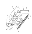
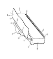
図1及び図2において、10はノンジフ式コネクタ、20はそこに嵌合される補強板付きフレキシブル基板である。コネクタ10は、PPS(ポリフェニレンサルファイド)等の合成樹脂から成るコネクタハウジング30と、ハウジング30の内部に複数配設されたリン青銅等の金属製の端子40と、ハウジング30の上部に組み込まれハウジング30と同じ材質から成るロック部材50とを有する。なお、60は、ハウジング30に装着された取付金具であり、ハウジング30を図示しない回路基板に固定するためのものである。
1 and 2, 10 is a non-diff connector, and 20 is a flexible board with a reinforcing plate fitted therein. The
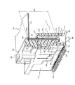
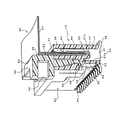
図3及び図4を用いてより詳細に本実施形態を説明するに、ハウジング30は、略直方体状を呈しており、補強板付きフレキシブル基板20の先端部分を挿抜するために上面に形成された細長い開口部31と、開口部31に繋げて内部に形成された基板挿入部32と、端子40が圧入される圧入溝33と、端子40が挿通・ガイドされる端子溝34と、ロック部材50の嵌合部51が嵌入される嵌合溝35と、端子40の位置決め用ガイド穴36と、基板20の先端部分が突き当たってその挿入深さを規制する突当部37とを備えている。突当部37の上面には、基板20の補強板22の下端が突き当てられる突当面37Xが形成されている。
The present embodiment will be described in more detail with reference to FIGS. 3 and 4. The
端子40は、基部41と、基部41から上方に延設されハウジング30の圧入溝33に嵌合し得る圧入部42と、基部41から大きく上方に延設されハウジング30の端子溝34に遊嵌される接触部43と、接触部43の先端部分に備えられた接点部44と、基部41から側方に延設され図示しない回路基板に実装されるテール部45と、ハウジング30のガイド穴36に対応するガイド片46と、圧入部42に形成された矢じり47とを有している。
The
因みに、ハウジング30に対し、端子40は、そのテール部45が1本毎に左側方、右側方の夫々に振り分けられるように、所謂千鳥配置されている。端子40は、そのテール部45が図1で25本、図2でも25本現れている通り、計50本がハウジング30に植設されている。勿論、端子40の全ての接点部44は、ハウジング30の内部(挿入部31)にあって同一方向を指向・整列配置されていることは言うまでもない。また、端子40は、ハウジング30の下方から上方に向けて圧入されるようになっている。
Incidentally, with respect to the
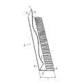
補強板付きフレキシブル基板20は、図5に示すように、フレキシブルな基板本体21と、基板本体21の先端部の一面に固着された補強板22とから構成されている。なお、説明の便宜上、以下フレキシブル基板20又は単に基板20と記した場合には、特に断りがない限り、基板本体21に補強板22を貼付して成る補強板付きフレキシブル基板20のことを示すものとする。
As shown in FIG. 5, the
基板本体21は、基板20の幅方向に間隔を隔てて複数配置された銅線等から成る導体23と、導体23を挟み込むように且つ導体23間に充填されるように配置されたポリエステル等の絶縁材から成るベースフィルム24、25とを有し、基板本体21の先端部分において、補強板22が固着されている側とは反対側のベースフィルム25が除去され、そこに導体23が露出されている。
The
基板本体21に固着される補強板22は、ポリエチレンテレフタレートの如き材料から成り、可撓性を有し、全面的に基板本体21に貼付されている。また、補強板22及び基板本体21の先端並びに両側端は、各々揃えられて略面一となっている。
The reinforcing
このような補強板付きフレキシブル基板20は、先端部分(補強板22が基板本体21に積層された部分)の剛性が高められているので、基板20の先端部分を上述のノンジフ式コネクタ10に挿入する際、端子40の接触部43を撓ませるための挿入抵抗が生じても、ワンアクションで円滑に挿入できるのである。そして、基板本体21の先端部分において導体23が露出されているので、これら導体23が端子40の接点部44が弾接することになる。
In such a
ロック部材50は、図1、図3及び図4に示すように、細長い開口部31の中央部に隣接させてハウジング30の上面に配置された本体52と、本体52から垂下されハウジング30の上面に形成された嵌合溝35に係合された嵌合部51と、ハウジング30に形成された引っ掛かり部38に係合するフック55と、本体52の上部から開口部31の上方を覆う方向(側方)に延設された係止部53とを有している。係止部53は、開口部31の幅方向に間隔を隔てて2個形成されており、係止部53の下面には、補強板22の上端26が当接されて係合される係止面53Xが形成されている。
As shown in FIGS. 1, 3, and 4, the
ロック部材50は、ハウジング30とは別にモールド成形されており、後に嵌合部51を嵌合溝35に挿入すると共にフック55を引っ掛かり部38に係合することで、ハウジング30にガタ無くしっかりと組み付けられて一体化される。このため、上述のように開口部31の上方に係止部53が突き出す構造となっていても、ハウジング30の成形金型が抜けないと言った事象は生じない。
The
このようにして一体化されたハウジング30とロック部材50とにおいて、突当部37の突当面37Xと係止部53の係止面53Xとの間隔W(図3参照)は、補強板22の高さH(図5参照)に略一致させてある。好ましくは、間隔Wを高さHよりも僅かに小さく設定し、コネクタ10に基板20が挿入された際、補強板22が突当面37Xと係止面53Xとの間で僅かに撓む或いは圧縮するように弾性変形して挟持されるようにする。また、これと合わせて或いはこれとは別個に、係止部53の自由端側が固定端側より僅かに下がるように係止面53Xを傾斜させて形成することで、抜止機能を付与してもよい。
In the
上述した補強板付きフレキシブル基板20に市販のフレキシブル基板をそのまま流用する場合には、その補強板22の高さHに合わせて突当面37Xと係止面53Xとの間隔Wを設定したコネクタ10を設計することになる。他方、コネクタ10の高さが制限される等の理由により、間隔Wが予め定められている場合には、この間隔Wに合致した高さHの補強板22を基板本体21に接着し、これを補強板付きフレキシブル基板20として用いる。
When the commercially available flexible board is used as it is for the
前記取付金具60は、図1〜図4中に、その詳細形状の表記が省略されているが、端子40の基部41及び圧入部42と類似する部位と、その部位から左右に延設された一対の取付部位とを有しており、前者部位がハウジング30に圧入され、後者部位が図示せぬ回路基板に半田付け固定されるようになっている。
1-4, the detailed shape is not shown in FIGS. 1 to 4, but a portion similar to the
本実施形態の作用を説明する。 The operation of this embodiment will be described.
コネクタ10に補強板付きフレキシブル基板20を挿入する際には、先ず、同基板20の導体23が露出された面の向きを、端子40の接点部44の方向に合致させる。次に、この基板20の先端部分をコネクタハウジング30の開口部31から挿入部32内に挿入する。この時、開口部31の上方にはロック部材50の係止部53が延出されているので、これを避けるべく、やや斜めに同基板20を挿入することになる。
When inserting the
この際、基板20は、補強板22の背面(基板本体21が接着されていない面)の先端がハウジング30の内壁39(図3、図4)上を滑りつつ、端子40の接点部44に当接してその接触部43を弾性変形させながら挿入部32に進入することになるので、所定の挿入抵抗を受けるが、補強板22によって剛性が高められているので、円滑に挿入させることができる。
At this time, the
更にフレキシブル基板20を進入させて行くと、補強板22の上記背面の先端が前記内壁39に接触することに加え、同背面が係止部53の先端にも当接するように成り、ここでやや挿入力を増して基板20を押し込めば、適度な剛性と弾性を兼ね備えた補強板22が弓の如く撓みながら挿入部32に進入する。その後、補強板22の先端が突当部37の突当面37Xに当接した瞬間に、補強板22の上端26が係止部53の係止面53Xの部分に潜り込み、補強板22は、係止部53を乗り越えるために必要としていた撓みの殆んどが解消されて、突当面37Xと係止面53Xとの間に保持される。
When the
これと同時に、基板20の導体23は端子40の接点部44に圧接し、同端子40が半田付けされている回路基板とフレキシブル基板20との間の電気接続が達成される。このとき、端子40の接触部43は、下部を起点として撓み、弾性変形する。
At the same time, the
この結果、補強板22が固着された基板20は、係止部53と突当部37とによって挟持され、しかも弾性変形した接触部43の復元力が作用する接点部44によって基板20が内壁39側(係止部53の反自由端側)に押圧されているので、特別な外力が作用しない限り、フレキシブル基板20がコネクタ10から抜け出すことはない。また、前述の如く突当面37Xと係止面53Xとの間隔Wを補強板22の高さHよりも僅かに小さくしておけば、補強板22が僅かに弾性変形した状態で間隔Wに挟持されるので一層抜け難くなる。また、係止部53の自由端側を僅かに下げるようにしておくことでも、抜止機能が発揮されて抜け難くなる。
As a result, the
一方、意思をもってこの基板20をコネクタ10から抜去する場合は、図1において、開口部31から上方に露出し且つロック部材50によって覆われていない補強板22の一部Aの辺りを指などで係止部53の自由端側に押し、補強板22を撓ませて弾性変形させてその上端26と前記係止部53との係合を解き、該上端26を自由にした上で同基板20を斜め上方に軽く引き抜くことで達成される。すなわち、ロック部材50及び係止部53が、細長い開口部31の長手方向の一部(図例では中央部)にのみ隣接されているので、開口部31から突出する補強板22には、ロック部材50及び係止部53によって覆われない部分(上記一部A)が生じることになり、この一部Aを指などで押すことでロックを解除できるのである。
On the other hand, when the
本実施形態においては、基板20は、前記特許文献1に記載のもののように、補強板の側方に突出部の如きものを設ける必要がないから、基板の幅が広くなり、コネクタの全幅すなわち基板実装面積を増大させるようなことはない。また、特許文献2に記載された補助部材のようなものを用意する必要も無いので、廉価な抜止構造とすることができる。
In the present embodiment, unlike the one described in
更に、先願(特願2005−124948号)に係る発明のように補強板に非固着部を設定する必要が無いので、基板をコネクタに挿入した姿の背が高くなってしまうようなことも無く、電子機器の小型化・薄型化等に応えることができる。また、既存の補強板付きフレキシブル基板を流用できる。 Furthermore, unlike the invention according to the prior application (Japanese Patent Application No. 2005-124948), there is no need to set a non-fixed portion on the reinforcing plate, so that the figure of inserting the board into the connector may become tall. It can respond to the downsizing and thinning of electronic devices. Moreover, the existing flexible board with a reinforcement board can be diverted.
なお、このコネクタ10は、スライダーやアクチュエータ等と言った可動部材を備えるジフ式では無く、基本的な構造がノンジフ式のままであるから、その特徴であるワンアクションでの基板20の挿入が可能であることは勿論である。
The
本発明は上記実施形態に限定されない。 The present invention is not limited to the above embodiment.
例えば、各図中、基板20の基板本体21は、補強板22の上端26の近傍において略直角方向に屈曲せしめてあるが、これは単にこの方向に該基板20の他端が連接される別のコネクタ等が存在しているイメージを示したに過ぎず、屈曲していることを含め、何ら特別の意味を持つものではなく、係止部53を避けつつ略垂直に伸びることを妨げない。
For example, in each figure, the
更に、突当部37(図3、図4)は、ハウジング20に設けられた例を示したが、端子40の基部41にこの役割を転嫁することもできる。
Furthermore, although the abutting part 37 (FIG. 3, FIG. 4) showed the example provided in the
加えて、係止部53の係止面53Xは、単に水平に形成するのみならず、既述のように係止部53の自由端側に向って僅かに下降する斜面としたり、或いは自由端の部分にて下方に少しだけ凸状を成すものとして、補強板22の抜止め・係止性の向上を図ってもよい。
In addition, the locking
また、ロック部材50及び係止部53は、図例のように細長い開口部31の長手方向の中央部に隣接させて配置したものに限定されることはなく、開口部31の両端部や一端部に隣接させて配置してもよい。要は、基板20を挿入してロックしたときに、補強板22にロック部材50及び係止部53によって覆われない部分(ロックを解除するために押圧される部分)が確保できればよい。
Further, the locking
また、係止面53Xの係止幅(係止部53の自由端から固定端までの長さ)を補強板22の厚さに合わせるようにし、基板20の基板本体21が係止面53Xによって無理に折り曲げられないようにしてもよい。
Further, the locking width of the
10 コネクタ
20 フレキシブル基板
21 基板本体
22 補強板
26 上端
30 コネクタハウジング
31 開口部
37 突当部
37X 突当面
50 ロック部材
53 係止部
53X 係止面
W 間隔
H 高さ
DESCRIPTION OF
Claims (4)
コネクタハウジングに、上記補強板付きフレキシブル基板を挿抜するための細長い開口部を形成し、上記ハウジングに、上記開口部の長手方向の一部に隣接させて、この開口部に上記補強板付きフレキシブル基板を挿入したとき、上記補強板の上端と係合するための係止部を設けたことを特徴とするノンジフ式コネクタの抜止構造。 A non-diffi fi er connector retaining structure in which a flexible substrate with a reinforcing plate formed by fixing a reinforcing plate having flexibility to the entire surface of the front end portion of the flexible substrate body is inserted and removed,
An elongated opening for inserting and removing the flexible board with the reinforcing plate is formed in the connector housing, and the housing is adjacent to a part of the opening in the longitudinal direction, and the flexible board with the reinforcing plate is placed in the opening. A locking structure for a non-diff connector, wherein a locking portion for engaging with the upper end of the reinforcing plate is provided.
該突当部と上記係止部との間に上記補強板が保持されてその上下動が規制されるようになっている請求項1記載のノンジフ式コネクタの抜止構造。 A striking portion against which the lower end of the flexible board with the reinforcing plate inserted into the opening is abutted;
2. The non-diffi fi er connector retaining structure according to claim 1, wherein the reinforcing plate is held betWeen the abutting portion and the locking portion to restrict the vertical movement thereof.
該ロック部材を、上記コネクタハウジングに固定して成る請求項1〜3いずれかに記載のノンジフ式コネクタの抜止構造。 The locking portion is formed on a lock member separate from the connector housing,
4. The non-diffi fi er connector retaining structure according to claim 1, wherein the lock member is fixed to the connector housing.
Priority Applications (6)
| Application Number | Priority Date | Filing Date | Title |
|---|---|---|---|
| JP2005334091A JP2007141663A (en) | 2005-11-18 | 2005-11-18 | Non-diffitype connector retaining structure |
| US11/911,350 US20090023324A1 (en) | 2005-04-14 | 2006-04-13 | Locking structure of flexible board |
| EP06731790A EP1879259A1 (en) | 2005-04-14 | 2006-04-13 | Locking structure of flexible board |
| KR1020077024104A KR20080005215A (en) | 2005-04-14 | 2006-04-13 | Locking Structure of Flexible Substrate |
| PCT/JP2006/307854 WO2006112363A1 (en) | 2005-04-14 | 2006-04-13 | Locking structure of flexible board |
| TW095113286A TW200642183A (en) | 2005-04-14 | 2006-04-14 | Locking structure of flexible board |
Applications Claiming Priority (1)
| Application Number | Priority Date | Filing Date | Title |
|---|---|---|---|
| JP2005334091A JP2007141663A (en) | 2005-11-18 | 2005-11-18 | Non-diffitype connector retaining structure |
Publications (1)
| Publication Number | Publication Date |
|---|---|
| JP2007141663A true JP2007141663A (en) | 2007-06-07 |
Family
ID=38204286
Family Applications (1)
| Application Number | Title | Priority Date | Filing Date |
|---|---|---|---|
| JP2005334091A Pending JP2007141663A (en) | 2005-04-14 | 2005-11-18 | Non-diffitype connector retaining structure |
Country Status (1)
| Country | Link |
|---|---|
| JP (1) | JP2007141663A (en) |
-
2005
- 2005-11-18 JP JP2005334091A patent/JP2007141663A/en active Pending
Similar Documents
| Publication | Publication Date | Title |
|---|---|---|
| KR100604304B1 (en) | Locking device of connector | |
| JP3925919B2 (en) | Electrical connector for connecting flat conductors | |
| US5562487A (en) | Electric connector | |
| US5445534A (en) | Double lock male/female type connector | |
| US6840797B2 (en) | Structure for engaging and releasing connectors | |
| CN102074820B (en) | Connector for substrate connection | |
| US7238032B2 (en) | Connector arrangement between a flat flex cable and a component | |
| EP1628366A1 (en) | Electric connector | |
| US20090023324A1 (en) | Locking structure of flexible board | |
| US6659794B2 (en) | Connector for connecting FFC | |
| CN101160695A (en) | Detachment prevention structure for flexible substrates | |
| JP2007287380A (en) | Double-sided FPC / FFC connector | |
| JP2007141663A (en) | Non-diffitype connector retaining structure | |
| JP6546973B2 (en) | Flat conductor connector | |
| JP2009104985A (en) | Connector with disconnection prevention mechanism | |
| US7559792B2 (en) | Connector with easily replacement of a slider | |
| JP2746142B2 (en) | connector | |
| KR100482532B1 (en) | Connector device for card | |
| JP4829808B2 (en) | connector | |
| JP2007242393A (en) | Non-Diff connector assembly | |
| JPH11121112A (en) | Electrical connector | |
| CN217562908U (en) | Needle stand | |
| JP2002015825A (en) | Low insertion force connector | |
| JPH10255926A (en) | connector | |
| JP2007311122A (en) | Flexible board connector |