JP2007140924A - Contact signal transmitting and receiving device - Google Patents
Contact signal transmitting and receiving device Download PDFInfo
- Publication number
- JP2007140924A JP2007140924A JP2005334110A JP2005334110A JP2007140924A JP 2007140924 A JP2007140924 A JP 2007140924A JP 2005334110 A JP2005334110 A JP 2005334110A JP 2005334110 A JP2005334110 A JP 2005334110A JP 2007140924 A JP2007140924 A JP 2007140924A
- Authority
- JP
- Japan
- Prior art keywords
- contact signal
- signal
- transmitting
- transmission
- contact
- Prior art date
- Legal status (The legal status is an assumption and is not a legal conclusion. Google has not performed a legal analysis and makes no representation as to the accuracy of the status listed.)
- Granted
Links
Images


Classifications
-
- H—ELECTRICITY
- H04—ELECTRIC COMMUNICATION TECHNIQUE
- H04L—TRANSMISSION OF DIGITAL INFORMATION, e.g. TELEGRAPHIC COMMUNICATION
- H04L12/00—Data switching networks
- H04L12/02—Details
- H04L12/10—Current supply arrangements
-
- H—ELECTRICITY
- H04—ELECTRIC COMMUNICATION TECHNIQUE
- H04L—TRANSMISSION OF DIGITAL INFORMATION, e.g. TELEGRAPHIC COMMUNICATION
- H04L12/00—Data switching networks
- H04L12/02—Details
- H04L12/12—Arrangements for remote connection or disconnection of substations or of equipment thereof
-
- H—ELECTRICITY
- H04—ELECTRIC COMMUNICATION TECHNIQUE
- H04L—TRANSMISSION OF DIGITAL INFORMATION, e.g. TELEGRAPHIC COMMUNICATION
- H04L41/00—Arrangements for maintenance, administration or management of data switching networks, e.g. of packet switching networks
- H04L41/02—Standardisation; Integration
- H04L41/0213—Standardised network management protocols, e.g. simple network management protocol [SNMP]
-
- H—ELECTRICITY
- H04—ELECTRIC COMMUNICATION TECHNIQUE
- H04L—TRANSMISSION OF DIGITAL INFORMATION, e.g. TELEGRAPHIC COMMUNICATION
- H04L41/00—Arrangements for maintenance, administration or management of data switching networks, e.g. of packet switching networks
- H04L41/04—Network management architectures or arrangements
- H04L41/046—Network management architectures or arrangements comprising network management agents or mobile agents therefor
-
- Y—GENERAL TAGGING OF NEW TECHNOLOGICAL DEVELOPMENTS; GENERAL TAGGING OF CROSS-SECTIONAL TECHNOLOGIES SPANNING OVER SEVERAL SECTIONS OF THE IPC; TECHNICAL SUBJECTS COVERED BY FORMER USPC CROSS-REFERENCE ART COLLECTIONS [XRACs] AND DIGESTS
- Y02—TECHNOLOGIES OR APPLICATIONS FOR MITIGATION OR ADAPTATION AGAINST CLIMATE CHANGE
- Y02D—CLIMATE CHANGE MITIGATION TECHNOLOGIES IN INFORMATION AND COMMUNICATION TECHNOLOGIES [ICT], I.E. INFORMATION AND COMMUNICATION TECHNOLOGIES AIMING AT THE REDUCTION OF THEIR OWN ENERGY USE
- Y02D30/00—Reducing energy consumption in communication networks
- Y02D30/50—Reducing energy consumption in communication networks in wire-line communication networks, e.g. low power modes or reduced link rate
Abstract
Description
本発明は、電気的に絶縁された設定制御のI/Fの技術に関する。 The present invention relates to an I / F technique for setting control that is electrically isolated.
送信側および受信側の装置間で伝達される信号として設定信号が知られている。この設定信号の伝達は、例えば、送信側装置に電源およびスイッチを設け、受信側装置に電球を置き、送信側装置と受信側装置とを2本のケーブル線で接続し、送信側装置のスイッチの開/閉により、受信側装置の電球を点燈或いは消灯させることにより行われる。接点信号の伝達に用いられるスイッチは、電気的に回路を開閉できるものであればよく、機械式のリレーやトランジスタ等が用いられる。また、上述の例では、回路の開閉を検知できるものとして電球を挙げて説明したが、LED(Light Emitting Diode)等が用いられることが多い。 A setting signal is known as a signal transmitted between devices on the transmission side and the reception side. The transmission of the setting signal is performed, for example, by providing a power source and a switch on the transmission side device, placing a light bulb on the reception side device, connecting the transmission side device and the reception side device with two cable lines, and switching the transmission side device. This is done by turning on or off the light bulb of the receiving side device by opening / closing. The switch used for transmitting the contact signal may be any switch that can electrically open and close the circuit, and a mechanical relay, a transistor, or the like is used. In the above example, the light bulb is described as being capable of detecting the opening and closing of a circuit, but an LED (Light Emitting Diode) or the like is often used.
従来の接点信号の送受信の技術には、受信装置側に電源を設ける方式において、
送信側装置および受信側装置の間の電流の向きを切り替える手法が知られている(例えば特許文献1)。特許文献1では、受信用電源方向切替部と、双方向の電流向きに対応した双方向電流検知部とを設けることで、電流の向きの切替えを実現している。
In the conventional contact signal transmission / reception technology, in the method of providing a power supply on the receiving device side,
A method of switching the direction of current between a transmission side device and a reception side device is known (for example, Patent Document 1). In
ところで、接点信号で制御される制御対象機器の制御仕様(以下「接点制御仕様」という)には、種々のものがある。そのため、複数種の制御対象機器を制御する制御装置は、異なる種類の接点制御仕様を持つ制御対象機器に対応できるように構成されていることが望ましい。例えば、接点制御仕様により、入力端子および出力端子の内訳が異なる場合があるため、入力端子および出力端子の内訳が異なる接点制御仕様に対応できるよう構成されていることが求められる。 By the way, there are various control specifications (hereinafter referred to as “contact control specifications”) of control target devices controlled by contact signals. Therefore, it is desirable that the control device that controls a plurality of types of control target devices is configured to be compatible with control target devices having different types of contact control specifications. For example, the breakdown of the input terminal and the output terminal may be different depending on the contact control specification, and therefore, the breakdown of the input terminal and the output terminal is required to be configured to be compatible with different contact control specifications.
また、接点信号により高信頼な制御を行う場合、接点信号の回路は、ある程度高い電圧のものが要求される。そのため、接点信号の送受信を行う回路の電圧は、制御用のマイコンなどに印加する電圧より高くなる。したがって、マイコン等の内部の素子を保護するために接点信号は、フォトカプラ等により内部の回路と絶縁されていることが必要になる。 In addition, when highly reliable control is performed using a contact signal, the contact signal circuit is required to have a high voltage to some extent. Therefore, the voltage of the circuit that transmits and receives contact signals is higher than the voltage applied to the control microcomputer or the like. Therefore, in order to protect internal elements such as a microcomputer, the contact signal needs to be insulated from the internal circuit by a photocoupler or the like.
上記特許文献1の技術は、接点信号を内部の回路と絶縁すること、および、電源が受信側に設けられている場合の電流の方向を切り替えることについては考慮されている。しかしながら、上記特許文献1の技術は、入力端子および出力端子の内訳が異なる制御仕様に対応するための手法について考慮されていない。なお、1つの端子の入出力を切り替える手法として、マイコンなどのI/Oピンで入力(DI)、出力(DO)を切り替えるものがある。しかし、この方法では、接点信号が絶縁されていないため、マイコンの電圧と異なる電圧で接点信号を送受信することができない。
The technique of the above-mentioned
本発明は、上記事情に鑑みてなされたものであり、本発明の目的は、絶縁素子で装置内部の回路と電気的に絶縁された、様々な接点制御仕様の信号の送受信を実現する設定制御I/Fを提供することにある。 The present invention has been made in view of the above circumstances, and an object of the present invention is to perform setting control that realizes transmission and reception of signals of various contact control specifications that are electrically insulated from the circuit inside the apparatus by an insulating element. To provide I / F.
上記課題を解決するため、本発明の一態様は、電気的に絶縁された接点信号の送受信を行う送受信部を有する接点信号送受信装置に適用される。 In order to solve the above problems, one embodiment of the present invention is applied to a contact signal transmission / reception apparatus including a transmission / reception unit that transmits and receives an electrically isolated contact signal.
そして、接点信号送受信装置は、前記接点信号の送受信を行うための複数の信号端子が設けられていて、前記送受信部は、前記複数の信号端子の中の少なくとも1つの信号端子を、前記接点信号を入力するための入力用端子、および前記接点信号を出力するための出力用端子のいずれか一方に選択して設定する入出力切替手段を有する。 The contact signal transmitting / receiving apparatus includes a plurality of signal terminals for transmitting / receiving the contact signals, and the transmitting / receiving unit transmits at least one signal terminal of the plurality of signal terminals to the contact signal. Input / output switching means for selecting and setting either one of an input terminal for inputting a signal and an output terminal for outputting the contact signal.
本発明によれば、電気的に絶縁された接点信号の送受信を行う送受信装置に、複数の信号端子の中の少なくとも1つの信号端子を入力用端子或いは出力用端子のいずれかに選択的に設定する手段を設けるようにしている。そのため、本発明によれば、電気的に絶縁された接点信号の送受信を行う送受信装置において、様々な接点制御仕様に対応した信号の送受信を実現する設定制御I/Fを提供することができる。 According to the present invention, in a transmission / reception device that transmits and receives an electrically isolated contact signal, at least one signal terminal of a plurality of signal terminals is selectively set as either an input terminal or an output terminal. Means to do this are provided. Therefore, according to the present invention, it is possible to provide a setting control I / F that realizes transmission / reception of signals corresponding to various contact control specifications in a transmission / reception device that transmits / receives electrically isolated contact signals.
以下、本発明の一実施形態が適用された制御装置について図面を用いて説明する。 Hereinafter, a control device to which an embodiment of the present invention is applied will be described with reference to the drawings.
図1は、本発明の一実施形態の制御装置を利用した制御システムの概略構成を説明するための図である。 FIG. 1 is a diagram for explaining a schematic configuration of a control system using a control device according to an embodiment of the present invention.
図示するように、制御システムは、制御装置100、制御装置100に制御される電源制御対象機器200a〜d、コンソールサーバ300、制御端末400、およびモデム500を有する。制御装置100は、電源制御対象機器200a〜dとケーブル150a〜dにより接続されている。また、制御装置100および制御端末400は、各々、LAN(Local Area Network)20に接続されている。制御端末400は、LAN20とは別にモデム500にも接続されている。モデム500は、電話回線40を介してコンソールサーバ300に接続されている。また、制御装置100とコンソールサーバ300とは、シリアル(例えばRS−232C)30により接続されている。なお、本実施形態の説明では、電源制御対象機器200a〜dを4台接続している場合を例示しているが、これは例示に過ぎない。電源制御対象機器200は、少なくとも1台あればよい。
As illustrated, the control system includes a
制御端末400は、図示しない入力装置を介して利用者からの指示を受付けて、LAN20やシリアル(例えばRS−232C)30経由で制御装置100に各種の指示(例えば、電源制御対象機器200に対する制御指示)を行う。
The
具体的には、制御装置100には、HTTP(HyperText Transfer Protocol)サーバとしての機能と、SNMP(Simple Network Management Protocol)エージェントとしての機能と、が設けられている。そして、制御装置100は、HTTPサーバとしての機能により、HTTPクライアントとしての機能を有する制御端末400とLAN20を介して通信を行い利用者からの指示を受け付ける。また、制御装置100は、SNMPエージェントとしての機能により、SNMPマネージャとしての機能を持つNMS(ネットワーク・マネージメント・システム)としての制御端末400とLAN20を介して通信を行い利用者からの指示を受付ける。
Specifically, the
また、本実施形態では、制御端末400は、電話回線40およびコンソールサーバ300を介して、シリアル30経由で制御装置100にアクセスすることもできる。すなわち、制御端末400は、電話回線40を経由して制御装置100に各種の指示を行うことができる。
In the present embodiment, the
そして、制御装置100は、制御端末400からの指示を受付けて、4つの機器(電源制御対象機器200a〜d)に対して、個別に、或いは連動して、接点信号を利用した電源のON/OFF等の制御を行なう。
Then, the
ここで、本実施形態の制御装置100が用いる接点信号について図10および11を用いて説明する。図10は、送信側装置および受信側装置との間で行なわれる設定信号の送受信を説明するための図である。
Here, contact signals used by the
図示するように、送信側に電源および3つのスイッチSWa〜cが設けられている。受信側には、スイッチSWaの開閉により点滅する電球aと、スイッチSWbの開閉により点滅する電球bと、スイッチSWcの開閉により点滅する電球cとが設けられている。 As shown in the figure, a power source and three switches SWa to SW are provided on the transmission side. On the receiving side, a light bulb a that blinks by opening and closing the switch SWa, a light bulb b that blinks by opening and closing the switch SWb, and a light bulb c that blinks by opening and closing the switch SWc are provided.
ところで、接点信号の送受信には、回路を流れる電流が往復するために少なくとも2本の線が必要になる。そして、複数の回路で接点信号を送受信する場合、それぞれの回路で必要な2本の線のうち1本を共通化することができる。図示する例では、受信側から送信側に戻る経路を、1本の線(common)に共通させている。この共通化させた線は、commonと呼ばれ、共通されなかった線は、信号線と呼ばれる。なお、送信側および受信側において、commonを接続する端子をcommon端子と呼ぶ。 By the way, in order to transmit and receive contact signals, at least two lines are required for the current flowing through the circuit to reciprocate. When a contact signal is transmitted and received by a plurality of circuits, one of the two lines necessary for each circuit can be shared. In the example shown in the figure, the path returning from the reception side to the transmission side is shared by a single line (common). This common line is called common, and the line that is not common is called a signal line. Note that, on the transmission side and the reception side, a terminal that connects common is referred to as a common terminal.
図示する例では、送信側から受信側に向かう経路を3本の信号線a〜cで接続している。具体的には、送信側のスイッチSWaと受信側の電球aとが信号線aを介して接続され、送信側のスイッチSWbと受信側の電球bとが信号線bを介して接続され、送信側のスイッチSWcと受信側の電球cとが信号線cを介して接続されている。なお、受信側で信号線を接続する端子を入力端子と呼び、送信側で信号線と接続する端子を出力端子と呼ぶ。 In the example shown in the figure, paths from the transmission side to the reception side are connected by three signal lines a to c. Specifically, the transmission-side switch SWa and the reception-side light bulb a are connected via a signal line a, the transmission-side switch SWb and the reception-side light bulb b are connected via a signal line b, and transmission The switch SWc on the side and the light bulb c on the reception side are connected via the signal line c. Note that a terminal that connects a signal line on the receiving side is called an input terminal, and a terminal that connects to the signal line on the transmitting side is called an output terminal.
そして、例えば、送信側のスイッチSWaを閉じれば、出力端子aを介して電流が信号線aを経由して受信側の電球aに流れて、その電流がcommonを経由して送信側に戻る。また、例えば、送信側のスイッチSWbを閉じれば、出力端子bを介して電流が信号線bを経由して受信側の電球bに流れ、その電流がcommonを経由して送信側に戻る。受信側では、スイッチSWa〜cの開閉に対応して電球が点燈或いは消灯することで各種の指示を受付ける。 For example, when the transmission-side switch SWa is closed, a current flows through the output terminal a via the signal line a to the reception-side light bulb a, and the current returns to the transmission side via the common. For example, if the transmission-side switch SWb is closed, a current flows through the output terminal b via the signal line b to the reception-side light bulb b, and the current returns to the transmission side via the common. On the receiving side, various instructions are received by turning on or off the light bulb in response to opening and closing of the switches SWa to c.
次に、図11を用いて、電源を送信側装置に持たせる場合と、電源を受信側装置に持たせる場合の接点信号の送受信の方式について説明する。 Next, with reference to FIG. 11, a contact signal transmission / reception method in the case where the power source is provided to the transmission side apparatus and the case where the power supply is provided to the reception side apparatus will be described.
図11は、電源を受信側装置および送信側装置のいずれに持たせるか、および、電流の流れる方向により分類される4種類の接点信号の送受信の方式を示している。 FIG. 11 shows four types of contact signal transmission / reception methods classified according to which of the receiving side device and the transmitting side device has a power source and the direction of current flow.
図示する「番号1」に示す接点信号の送受信方式1は、受信装置側に電源が設けられ、commonから信号線に電流が流れる方式を示している。「番号2」に示す接点信号の送受信方式2は、受信装置側に電源が設けられ、信号線からcommonに電流が流れる方式を示している。「番号3」に示す接点信号の送受信方式3は、送信装置側に電源が設けられ、commonから信号線に電流が流れる方式を示している。「番号4」に示す接点信号の送受信方式4は、送信装置側に電源が設けられ、信号線からcommonに電流が流れる方式を示している。
The contact signal transmission /
図示する例では、上述した図10で説明したスイッチおよび電球の代わりにフォトカプラを用いている。フォトカプラは、LEDとフォトトランジスタとを組合せた素子で、LEDの正方向に電流が流れるとLEDが発行し、フォトトランジスタの正方向に電流が流れる。なお、図示する4つの方式により、commonと信号線に対して、LED、フォトトランジスタ、および電源をどの向きにおくのかが決る。このように電気信号を一旦光に変換することにより、LED側とフォトトランジスタ側で電気的な絶縁を行う。その結果、送信側装置および受信側装置の内部の制御用の素子(例えば、マイコン)を保護することができる。 In the illustrated example, a photocoupler is used instead of the switch and the light bulb described in FIG. A photocoupler is an element in which an LED and a phototransistor are combined. When a current flows in the positive direction of the LED, the LED issues, and a current flows in the positive direction of the phototransistor. The four systems shown in the figure determine the direction in which the LED, the phototransistor, and the power supply are arranged with respect to common and the signal line. Thus, by electrically converting the electrical signal into light, electrical insulation is performed on the LED side and the phototransistor side. As a result, it is possible to protect control elements (for example, a microcomputer) inside the transmission side device and the reception side device.
ところで、2つの装置(例えば、装置Aおよび装置Bの2つの装置)の間において、接点信号で通信を行う場合、装置Aから装置B、或いは、装置Bから装置Aに一方的に信号を送ることは少ない。装置Aから装置Bへと、装置Bから装置Aへの両方向で信号を送受信することが一般的である。この場合、装置Aおよび装置Bは、いずれも送信側でもあり受信側でもある。そのため、装置Aおよび装置Bは、複数の入力・出力端子を持つこととなる。 By the way, when communication is performed using a contact signal between two devices (for example, two devices of device A and device B), a signal is unilaterally transmitted from device A to device B or from device B to device A. There are few things. It is common to send and receive signals in both directions from device A to device B and from device B to device A. In this case, both device A and device B are both transmitting and receiving. Therefore, the devices A and B have a plurality of input / output terminals.
また、装置AからBへの送受信の方式と、装置Bから装置Aへの送受信の方式とが同じであるとは限らない。例えば、装置Aから装置Bへの接点信号の送受信には、図示する「番号1」の送受信方式が採用され、装置Bから装置Aへの接点信号の送受信には、図示する「番号3」の送受信方式を採用されることもある。この場合、電源は装置Bだけに持たせればよいこととなるため、装置Aを小型化できる。 Further, the transmission / reception method from the device A to the device B and the transmission / reception method from the device B to the device A are not necessarily the same. For example, the transmission / reception method of “No. 1” shown in the figure is adopted for the transmission / reception of the contact signal from the apparatus A to the apparatus B, and the transmission / reception system of the “No. 3” shown in the figure is used for the transmission / reception of the contact signal from the apparatus B to the apparatus A. A transmission / reception method may be employed. In this case, since the power source only needs to be provided to the device B, the device A can be reduced in size.
このように、接点信号の送受信には、上述した4つの送受信方式に分類することがきるため、制御装置が、4つの送受信方式に対応できるように構成されていることが望ましい。本実施形態の制御装置100は、後述するが、4つの送受信方式に対応できるように構成されている。また、本実施形態の制御装置100は、接点信号の送受信のための端子を選択的に入力用および出力用のいずれかに設定できるようにしている。したがって、本実施形態では、制御装置100は、様々な接点制御仕様に対応することができる。
As described above, since the contact signal transmission / reception can be classified into the above-described four transmission / reception methods, it is desirable that the control device is configured to be compatible with the four transmission / reception methods. As will be described later, the
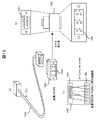
続いて、本実施形態の制御装置100の外観および接点信号を送受信するためのポートの構成を説明する。図2は、本実施形態の制御装置100、および、制御装置100に接続するためのケーブル150の外観を例示した図である。
Next, the appearance of the
図示するように、制御装置100は、電源制御装置200a〜dとの間で接点信号を送受信するためのケーブル150を接続するためのポート110a〜100dを有している。また、制御装置100は、シリアル30と接続するためのシリアル用ジャック120と、LAN20と接続するためのLAN用ジャック130とを有している。
As illustrated, the
ポート100a〜dとケーブル150とは、例えば、D―SUB9ピン等の比較的容易かつ安価に入手できる規格品(標準のD―SUB9ピンのシリアルクロスケーブル等)を用いるようにすればよい。図示する例では、ポート110a〜100dは、9つの端子(入力用端子、出力用端子、およびcommon端子)が設けられている。
For the ports 100a to 100d and the
また、ケーブル150は、そのままでは、電源制御機器200a〜d側のコネクタと形状が異なる場合がある。そのような場合、図示するように、電源制御機器200a〜dのコネクタ形状に対応させた変換コネクタ160を利用する。
In addition, the shape of the
ここで、変換コネクタ160の例を図12に示す。図12は、変換コネクタの一例を説明するための図である。図12では、(a)図に変換コネクタ160の外観を示し、(b)図に変換コネクタ160のコネクタ形状の外観を示し、(c)図に変換コネクタ160のピン間の接続関係を示している。
An example of the
図示するように、変換コネクタ160は、9つの端子(9pin)を持つコネクタ部161と、6つの端子(6pin)を持つコネクタ部162とを備えている。変換コネクタ160は、「9pin」から「6pin」へのピン数変換と、コネクタ形状の変換とを行う。なお、変換コネクタ160のコネクタのピン間の接続は、例えば、図12(c)に示すようにする。図12(c)では、「9pin」側の「端子1」を「6pin」側の「端子1」に接続し、「9pin」側の「端子3」を「6pin」側の「端子3」に接続し、「9pin」側の「端子5」を「6pin」側の「端子2」に接続し、「9pin」側の「端子6」を「6pin」側の「端子4」に接続し、「9pin」側の「端子8」を「6pin」側の「端子6」に接続し、「9pin」側の「端子9」を「6pin」側の「端子5」に接続している。なお、変換コネクタ160の「9pin」側の「端子2」、「端子4」、および「端子7」は、「6pin」側の端子に接続していない。そして、変換コネクタ160により、コネクタ形状だけでなく、ピン配置(各ピンをどのピンにアサインするのか)の変換も行うことができる。
As illustrated, the
なお、上記の説明では、変換コネクタ160でピン数およびコネクタ形状の変換を行う場合を説明したが、接続ケーブル150により、ピン数およびコネクタ形状の変換を行うようにしてもよい。さらに、この場合、接続ケーブル150が、ピン配置(各ピンをどのピンにアサインするのか)の変換も行うようにしてもよい。
In the above description, the case where the
ここで、ピン配置は、制御装置100内部のマイコンが実行するソフトウェアで変更することも可能である。しかし、マイコンのソフトウェアでは、common端子のアサインまで変更することはできない(common端子のアサインは、物理的に接続を変える必要がある)。そのため、上述のように、変換コネクタ160(或いは変換ケーブル150)を利用することにより、common端子のアサインの変更を行うことが可能になる。
Here, the pin arrangement can be changed by software executed by a microcomputer in the
続いて、本実施形態の制御装置100内のプリント基板の構成を説明する。図3は、本実施形態の制御装置100が有するプリント基板のブロック図である。
Next, the configuration of the printed circuit board in the
図示するように、プリント基板は、商用の100V電源を「±12V」に変換する電源変換器1200、各種の処理を行うマイコン1100、ISOIN1110a〜d、ISOOUT1120a〜d、ポート110a〜d、RS−232Cドライバ1130、シリアル用入出力端子120、PHY(フィジカル層)1140、パルストランス1150、およびLAN用入出力端子130を有する。
As shown in the figure, the printed circuit board includes a
マイコン1100は、ケーブル150(図1参照)を介して電源制御機器200a〜dに対する制御処理を行う。電源変換器1200は、商用の100V電源を「±12V」に変換し、その変換した電源を、接点信号の送受信処理を行うための電源としてISOIN1110a〜dおよびISOOUT1120a〜dに供給する。ISOIN1110a〜dおよびISOOUT1120a〜dは、それぞれ、入力・出力用のフォトカプラと、その周りの回路を含めた素子であり、接点信号の送受信処理を行う。そして、ISOIN1110a〜dおよびISOOUT1120a〜dは、各ポート110a〜dの接点信号の入力信号群および出力信号群の端子に接続されている。そして、本実施形態では、後述する手法により、ポート毎に入力、出力の送受信方式を変更する。
The
さらに、マイコン1100は、RS−232ドライバ1130を制御して、シリアル用入出力端子120を経由しての通信処理を行う。また、マイコン1100は、PHY1140およびパルストランス1150を制御して、LAN用入出力端子130を経由しての通信処理を行う。
Further, the
なお、マイコン1100が行う上述の処理は、図示しないメモリに記憶されているプログラムをマイコン1100が実行することにより実現される。
The above-described processing performed by the
続いて、本実施形態の制御装置100が電源制御対象機器200に行う接点信号による制御の仕様について図4を用いて説明する。図4は、本実施形態の電源制御対象機器に対する制御仕様の一例を示した図である。
Next, specifications of control by contact signals performed by the
図示する例では、制御装置100の出力信号として電源投入保持信号S1および電源投入指示信号S2を示し、制御装置100の入力信号として電源投入完了信号S3を示している。
In the illustrated example, a power-on holding signal S1 and a power-on instruction signal S2 are shown as output signals of the
制御装置100は、電源制御対象機器200の電源を「ON」に設定する制御を行う際には、電源投入保持信号S1の出力を「ON」にした状態で電源投入指示信号S2の出力を「ON」にする。そして、電源投入保持信号S1が「ON」であり、かつ電源投入指示信号S2が「ON」の場合、電源制御対象機器200側では電源の投入が開始される。電源制御対象機器200は、電源投入が開始された際、電源投入完了信号S3を「ON」にする。
When the
制御装置100は、電源制御対象機器200からの入力信号である電源投入信号S3が「ON」になった場合(電源制御対象機器200が出力する電源投入信号S3が「ON」になった場合)、電源投入指示信号S2の出力を「OFF」にする。 When the power-on signal S3, which is an input signal from the power control target device 200, is “ON”, the control device 100 (when the power-on signal S3 output from the power control target device 200 is “ON”). Then, the output of the power-on instruction signal S2 is turned “OFF”.
制御装置100は、電源制御対象機器200の電源を「OFF」にする場合、電源投入保持信号S1を「OFF」にする。電源制御対象機器200は、電源投入保持信号S1が「OFF」になると、電源切断処理を開始し、電源切断か完了した際に電源投入完了信号S3を「OFF」にする。
When the power of the power control target device 200 is “OFF”, the
なお、図示する例は、電源制御対象機器200からの入力信号が1つである単純な制御を示しているが、これは例示に過ぎない。そして、このようなプロトコルによる通信が電源制御対象機器200毎に行われる。 Note that the illustrated example shows simple control in which there is one input signal from the power control target device 200, but this is merely an example. Communication according to such a protocol is performed for each power control target device 200.
続いて、本実施形態の制御装置100が有するポート100で受付ける接点信号と、制御装置100のマイコン1100との関係について、図5および図6を用いて説明する。
Subsequently, a relationship between a contact signal received by the
図5は、本実施形態の制御装置100のISOIN1110或いはISOOUT1120と、マイコン1100との関係を説明するための図である。
FIG. 5 is a diagram for explaining the relationship between the
図示するように、ISOIN1110(またはISOOUT1120)は、受信用電源有無・方向切替部2000、送信用電源有無・方向切替部2100、入出力切替部2200、双方向電流検知部2300、および双方向回路開閉部2400を有する。
As shown in the figure, ISOIN 1110 (or ISOOUT 1120) includes a receiving power supply presence / absence /
受信用電源有無・方向切替部2000は、common端子(図5には図示しせず)を介して受信用commonに接続されている。そして、受信用電源有無・方向切替部2000は、受信方式の選択を行なう。具体的には、受信用電源有無・方向切替部2000は、電源が受信側(ここでは、制御装置100側)にあるか、或いは送信側や外部などの受信側以外にあるかの選択と、電流の方向の選択とを行う。
The receiving power supply presence / absence /
送信用電源有無・方向切替部2100は、common端子(図5には図示しせず)を介して送信用commonに接続されている。そして、送信用電源有無・方向切替部2100は、送信方式の選択を行なう。具体的には、送信用電源有無・方向切替部2100は、電源が送信側(ここでは、制御装置100側)にあるか、あるいは受信側や外部などの送信側以外にあるかの選択と、電流の方向の選択とを行う。
The transmission power supply presence / absence /
また、ポート110の入出力端子毎に、入出力切替部2200と、双方向電流検知部2300と、双方向回路開閉部2400とが設けられている。なお、以下の説明において、入出力端子とは、ポート110の端子の中で、common端子以外の端子をいう。
For each input / output terminal of the port 110, an input /
双方向電流検知部2300は、接点信号側の双方向に流れる電流を検知するものであり、接点信号とマイコン1100に接続される内部回路とを絶縁している。双方向回路開閉部2400は、接点信号側に対して双方向に電流を流すものであり、接点信号とマイコン1100に接続される内部回路とを絶縁している。
The bidirectional
入出力切替部2200は、入出力端子を介して信号線に接続されている。そして、入出力切替部2200は、信号線を双方向電流検知部2300に接続するか、双方向回路開閉部2400に接続するかを切り替える。入出力切替部2200が信号線を双方向電流検知部2300に接続する場合、その信号線に接続されている入出力端子は、入力端子となる。入出力切替部2200が信号線を双方向回路開閉部2400に接続している場合には、その信号線に接続されている入出力端子は、出力端子となる。
The input /
双方向電流検知部2300および双方向回路開閉部2400は、それぞれ、入出力切替部2200を介して、マイコン1100のI/Oピンと信号線とを接続する。マイコン1100のI/Oピンから見ると双方向電流検知部2300からは入力のレベル信号が接続されていて、双方向回路開閉部2400へは出力レベル信号が接続されていることとなる。I/Oピンは、入力用および出力用で1つずつ用意しても良いが、双方向電流検知部2300および双方向電流開閉部2400の2つの回路をうまく構成すれば、1つのI/OピンをI/O切替で共通して使うことができる。
The bidirectional
図6は、本実施形態の制御装置が有するポートの接点信号の各端子に接続するISOIN1110、或いはISOOUT1120と、制御装置内部のマイコン1100のI/Oピン以外の範囲の回路を表したものある。
FIG. 6 shows a circuit in a range other than the ISOIN 1110 or ISOOUT 1120 connected to each terminal of the contact signal of the port included in the control device of the present embodiment and the I / O pin of the
図示するように、本実施形態では、受信用電源有無・方向切替部2000および送信用電源有無・方向切替部2100の設定を、ジャンパピンで行う。なお、図示する例では、ジャンパピンにより、受信用電源有無・方向切替部2000および送信用電源有無・方向切替部2100の設定を行う場合を説明するがこれは例示に過ぎない。例えば、受信用電源有無・方向切替部2000および送信用電源有無・方向切替部2100の設定をジャンパピンに代えて、リード線やスイッチにより行うようにしてもよい。また、受信用電源有無・方向切替部2000および送信用電源有無・方向切替部2100の設定をマイコン1100からの信号により設定するようにしてもよい。
As shown in the figure, in the present embodiment, the setting of the reception power supply presence / absence /
さて、図示するように受信用電源有無・方向切替部2000および送信用電源有無・方向切替部2100には、それぞれ、3つの端子(ジャンパピン用端子)を左右2列に並べた端子群2001が設けられている。具体的には、送信用電源有無・方向切替部2100に端子群2001aが設けられていて、受信用電源有無・方向切替部2000に端子群2001bが設けられている。
As shown in the figure, the receiving power supply presence / absence /
そして、「右上」および「右中央」のジャンパピン用端子と、「左中央」および「左下」のジャンパピン用端子とをそれぞれ接続した場合、自分側に電源があり、かつ電流の向きがcommonから信号線に流れる設定となる。また、「右中央」および「右下」のジャンパピン用端子と、「左上」および「左中央」のジャンパピン用端子とをそれぞれ接続した場合、自分側に電源があり、かつ電流の向きが信号線からcommonに流れる設定となる。「左中央」および「右中央」のジャンパピン用端子を接続した場合、自分側に電源がない設定となる。 And if the “upper right” and “right center” jumper pin terminals are connected to the “left center” and “lower left” jumper pin terminals, respectively, there is a power supply on its own side and the current direction is common. To the signal line. Also, if the “right center” and “bottom right” jumper pin terminals are connected to the “upper left” and “left center” jumper pin terminals, respectively, there is a power supply on its own side and the current direction is It is set to flow from the signal line to common. When the “Left Center” and “Right Center” jumper pin terminals are connected, there is no power supply on their own side.
入出力切替部2200は、信号線に接続している入出力端子を双方向電流検知部2300および双方向回路開閉部2400のいずれか一方に接続させる。具体的には、入出力切替部2200は、入出力端子と接続されているジャンパピン用端子2220と、双方向電流検知部2300に接続されているジャンパピン用端子2210と、双方向回路開閉部2400に接続されているジャンパピン用端子2230とを有する。
The input /
そして、図示する例では、ジャンパピン用端子2210とジャンパピン用端子2220とを接続した場合、入出力端子が双方向電流検知部2300に接続される。この場合、入出力端子は、入力用の端子となる。一方、ジャンパピン用端子2230とジャンパピン用端子2220とを接続した場合、入出力端子が双方向回路開閉部2400に接続される。この場合、入出力端子は、出力用の端子となる。
In the illustrated example, when the
なお、図示する例では、入出力切替部2200の設定をジャンパピンにより行う場合を例示しているが、特にこれに限定されるものではない。入出力切替部2200の設定も、上述した受信用電源有無・方向切替部2000および送信用電源有無・方向切替部2100と同様、リード線、スイッチ、或いはマイコン1100により行うようにしてもよい。
In the illustrated example, the input /
また、双方向電流検知部2300は、逆向きに2つのLEDを並列に接続した形のフォトカプラを使用し、フォトトランジスタの接点出力をレベル信号に抵抗するため抵抗でVcc(3.3V)にプルアップしている。双方向回路開閉部2400は、フォトリレーを使い双方向に電流を流せるようにしている。
In addition, the bidirectional
このように構成された双方向電流検知部2300および双方向回路開閉部2400の、マイコンのI/Oピンに接続されるレベル信号は、1つのI/Oピンに共通して接続することができる。その結果、ポートの1つの入出力端子を入力用と出力用とに設定で使い分けることができる。
The level signal connected to the I / O pin of the microcomputer of the bidirectional current detecting
なお、本実施形態の制御装置100では、ポート110に設けられた入出力端子の全てを入出切替えが可能な構成にする必要はない。入力用および出力用とも必要と思われる本数分は、予め入力専用端子および出力専用端子としておいてもよい。例えば、ポート110の端子のうち少なくとも1つの端子を入出力切替えが可能な構成にしておいて、その他の端子は、入力専用端子および出力専用端子としておいてもよい。
In the
また、本実施形態では、上述した図6に示すように、受信用commonおよび送信用commonの両者を開にすることができるようにフォトリレーを噛ませている。このように構成することで、受信用commonおよび送信用commonの両者を開にすれば、全ての入出力信号を開にすることができる。 Further, in the present embodiment, as shown in FIG. 6 described above, the photo relay is engaged so that both the reception common and the transmission common can be opened. With this configuration, all the input / output signals can be opened by opening both the reception common and the transmission common.
続いて、本実施形態の変形例について説明する。 Then, the modification of this embodiment is demonstrated.
図7は、上述した制御装置100の入出力用切替部2200をマイコン1100のIOピンから設定するための回路構成を示した図である。このように構成してもジャンパピンによる場合と同様の効果を奏することができる。なお、受信用電源有無・方向切替部2000および送信用電源有無・方向切替部2100の設定についても同様にマイコン1100のIOピンから設定するようにしてもよい。
FIG. 7 is a diagram illustrating a circuit configuration for setting the input /
図8は、図6で示した双方向電流検知部2300が有する逆並列接続したフォトカプラと同様の機能を通常の極性を持ったフォトカプラで実現する場合の回路構成を示している。このように双方向電流検知部2300の構成を変形しても上述と同様の作用効果を奏することができる。
FIG. 8 shows a circuit configuration when a function similar to that of the anti-parallel connected photo coupler included in the bidirectional
また、図9は、図6で示した双方向回路開閉部2400のフォトリレーを通常の極性を持ったフォトカプラで実現する場合の回路構成を示している。このように双方向回路開閉部2400の構成を変形しても上述と同様の作用効果を奏することができる。
FIG. 9 shows a circuit configuration in the case where the photorelay of the bidirectional circuit opening /
なお、本発明は、以上で説明した実施形態に限定されるものではなく、本発明の要旨の範囲内において種々の変形が可能である。例えば、本実施形態において、制御装置100のポート110に接続するケーブル150により、信号端子(入出力端子、common端子)への接点信号のアサインの変更を行うようにしてもよい。
The present invention is not limited to the embodiment described above, and various modifications can be made within the scope of the gist of the present invention. For example, in this embodiment, the assignment of the contact signal to the signal terminal (input / output terminal, common terminal) may be changed by the
20…LAN、30…シリアル、40…電話回線、100…制御装置、110…ポート、120…シリアル用ジャック、130…LAN用ジャック、150…ケーブル、160…変換コネクタ、200…電源制御対象機器、300…コンソールサーバ、400…制御端末、500…モデム、1100…マイコン、1110…ISOIN、1120…ISOOUT、1130…RS−232ドライバ、1140…PHY、1150…パルストランス、1200…電源変換器、2000…受信用電源有無・方向切替部、2100…送信用電源有無・方向切替部、2200…入出力切替部、2300…双方向電流検知部、2400…双方向回路開閉部
20 ... LAN, 30 ... serial, 40 ... telephone line, 100 ... control device, 110 ... port, 120 ... serial jack, 130 ... LAN jack, 150 ... cable, 160 ... conversion connector, 200 ... power control target device, DESCRIPTION OF
Claims (9)
前記接点信号の送受信を行うための複数の信号端子が設けられていて、
前記送受信部は、
前記複数の信号端子の中の少なくとも1つの信号端子を、前記接点信号を入力するための入力用端子、および前記接点信号を出力するための出力用端子のいずれか一方に選択して設定する入出力切替手段を有すること
を特徴とする接点信号送受信装置。 A contact signal transmission / reception device having a transmission / reception unit for transmitting / receiving an electrically isolated contact signal,
A plurality of signal terminals for transmitting and receiving the contact signal are provided,
The transceiver unit is
An input that selects and sets at least one signal terminal of the plurality of signal terminals as one of an input terminal for inputting the contact signal and an output terminal for outputting the contact signal. A contact signal transmitting / receiving apparatus comprising an output switching means.
前記送受信部が行う設定信号の送受信を制御する制御部を有し、
前記入出力切替手段は、前記入力用端子および出力用端子のいずれか一方への選択を前記制御部からの電気信号にしたがい行うこと
を特徴とする接点信号送受信装置。 The contact signal transmitting / receiving apparatus according to claim 1,
A control unit for controlling transmission / reception of a setting signal performed by the transmission / reception unit;
The contact signal transmitting / receiving apparatus according to claim 1, wherein the input / output switching means selects one of the input terminal and the output terminal in accordance with an electric signal from the control unit.
受信用の電源が自身に設けられているか否かの設定、送信用の電源が自身に設けられているか否かの設定、および、前記接点信号を流す方向の設定を行う送受信方式設定手段を有すること
を特徴とする接点信号送受信装置。 The contact signal transmitting / receiving apparatus according to claim 1,
It has a transmission / reception method setting means for setting whether or not a receiving power source is provided, setting whether or not a transmitting power source is provided, and setting the direction in which the contact signal flows. A contact signal transmitting / receiving apparatus characterized by the above.
前記入出力切替手段は、前記入力用端子および出力用端子のいずれか一方への選択を前記制御部からの電気信号にしたがい行い、
前記送受信方式設定手段は、前記受信用の電源が自身に設けられているか否かの設定、送信用の電源が自身に設けられているか否かの設定、および、前記接点信号を流す方向の設定を前記制御部からの電気信号にしたがい行うこと
を特徴とする接点信号送受信装置。 The contact signal transmitting / receiving apparatus according to claim 3,
The input / output switching means performs selection to either one of the input terminal and the output terminal according to an electrical signal from the control unit,
The transmission / reception method setting means sets whether or not the reception power supply is provided, sets whether or not the transmission power supply is provided, and sets the direction in which the contact signal flows Is performed according to an electrical signal from the control unit.
前記接点信号の送受信を行うための複数の信号端子を有するポートを有し、
前記ポートは、前記接点信号で通信を行う通信対象機器毎に複数設けられていて、
前記ポート毎に、前記ポートが有する複数の信号端子の中の少なくとも1つの信号端子を、前記接点信号を入力するための入力用端子、および前記接点信号を出力するための出力用端子のいずれか一方に選択して設定する入出力切替手段と、
前記ポート毎に、受信用の電源が自身に設けられているか否かの設定、送信用の電源が自身に設けられているか否かの設定、および、前記接点信号を流す方向の設定を受付ける送受信方式設定手段と、を有すること
を特徴とする接点信号送受信装置。 A contact signal transmission / reception device having a transmission / reception unit for transmitting / receiving an electrically isolated contact signal,
A port having a plurality of signal terminals for transmitting and receiving the contact signal;
A plurality of the ports are provided for each communication target device that communicates with the contact signal,
For each of the ports, any one of a plurality of signal terminals included in the port, an input terminal for inputting the contact signal, and an output terminal for outputting the contact signal I / O switching means to select and set to one,
For each port, transmission / reception accepting a setting as to whether or not a receiving power source is provided, a setting as to whether or not a transmitting power source is provided, and a setting of a direction in which the contact signal is supplied A contact signal transmitting / receiving apparatus comprising: a method setting unit;
前記設定信号の送受信を制御するためのマイコンが設けられた制御部を有し、
前記ポートが有する複数の信号端子への接点信号のアサインを前記マイコンのプログラムにより変更できること
を特徴とする接点信号送受信装置。 The contact signal transmitting / receiving apparatus according to claim 5,
A control unit provided with a microcomputer for controlling transmission and reception of the setting signal;
A contact signal transmitting / receiving apparatus, wherein assignment of contact signals to a plurality of signal terminals of the port can be changed by a program of the microcomputer.
前記ポートには、前記通信対象機器との間で接点信号を送受信するための接続ケーブルを接続するためのコネクタが設けられていて、さらに、
前記ポートに設けられたコネクタの形状を、前記通信対象機器に設けられたコネクタの形状に変換するための変換コネクタを有すること
を特徴とする接点信号送受信装置。 The contact signal transmitting / receiving apparatus according to claim 5,
The port is provided with a connector for connecting a connection cable for transmitting and receiving contact signals with the communication target device, and
A contact signal transmitting / receiving apparatus, comprising: a conversion connector for converting a shape of a connector provided in the port into a shape of a connector provided in the communication target device.
前記変換コネクタは、前記ポートが有する複数の信号端子への接点信号のアサインを変更すること
を特徴とする接点信号送受信装置。 The contact signal transmitting / receiving apparatus according to claim 7,
The said conversion connector changes the assignment of the contact signal to the several signal terminal which the said port has, The contact signal transmission / reception apparatus characterized by the above-mentioned.
前記ポートには、前記通信対象機器との間で接点信号を送受信するための接続ケーブルを接続するためのコネクタが設けられていて、
前記コネクタには、前記接続ケーブルが接続されていて、
前記接続ケーブルは、前記ポートが有する複数の信号端子への接点信号のアサインを変更すること
を特徴とする接点信号送受信装置。
The contact signal transmitting / receiving apparatus according to claim 5,
The port is provided with a connector for connecting a connection cable for transmitting and receiving contact signals with the communication target device,
The connection cable is connected to the connector,
The contact signal transmitting / receiving apparatus according to claim 1, wherein the connection cable changes assignment of contact signals to a plurality of signal terminals of the port.
Priority Applications (2)
| Application Number | Priority Date | Filing Date | Title |
|---|---|---|---|
| JP2005334110A JP4585959B2 (en) | 2005-11-18 | 2005-11-18 | Contact signal transmitter / receiver |
| US11/600,038 US20070115136A1 (en) | 2005-11-18 | 2006-11-16 | Contact signal transmission and reception apparatus |
Applications Claiming Priority (1)
| Application Number | Priority Date | Filing Date | Title |
|---|---|---|---|
| JP2005334110A JP4585959B2 (en) | 2005-11-18 | 2005-11-18 | Contact signal transmitter / receiver |
Publications (2)
| Publication Number | Publication Date |
|---|---|
| JP2007140924A true JP2007140924A (en) | 2007-06-07 |
| JP4585959B2 JP4585959B2 (en) | 2010-11-24 |
Family
ID=38052940
Family Applications (1)
| Application Number | Title | Priority Date | Filing Date |
|---|---|---|---|
| JP2005334110A Expired - Fee Related JP4585959B2 (en) | 2005-11-18 | 2005-11-18 | Contact signal transmitter / receiver |
Country Status (2)
| Country | Link |
|---|---|
| US (1) | US20070115136A1 (en) |
| JP (1) | JP4585959B2 (en) |
Cited By (3)
| Publication number | Priority date | Publication date | Assignee | Title |
|---|---|---|---|---|
| JP2017073029A (en) * | 2015-10-08 | 2017-04-13 | 株式会社デンソーウェーブ | Circuit board |
| JP2017112538A (en) * | 2015-12-17 | 2017-06-22 | 株式会社東芝 | Optical coupling device |
| WO2021002051A1 (en) * | 2019-07-02 | 2021-01-07 | オムロン株式会社 | Counter unit |
Citations (7)
| Publication number | Priority date | Publication date | Assignee | Title |
|---|---|---|---|---|
| JPS58167903U (en) * | 1982-04-29 | 1983-11-09 | シャープ株式会社 | Sequence controller input/output device |
| JPH0458705U (en) * | 1990-09-28 | 1992-05-20 | ||
| JPH05204417A (en) * | 1992-01-27 | 1993-08-13 | Sharp Corp | Input/output circuit for programable controller |
| JPH08171405A (en) * | 1994-12-20 | 1996-07-02 | Hitachi Ltd | Programmable controller |
| JPH08202478A (en) * | 1995-01-26 | 1996-08-09 | Hitachi Ltd | Signal gathering device |
| JPH11304905A (en) * | 1998-04-21 | 1999-11-05 | Jatco Corp | Gps information sharing equipment |
| JP2002073117A (en) * | 2000-08-30 | 2002-03-12 | Hitachi Ltd | Function selection type input and output circuit |
Family Cites Families (1)
| Publication number | Priority date | Publication date | Assignee | Title |
|---|---|---|---|---|
| US4593380A (en) * | 1984-06-04 | 1986-06-03 | General Electric Co. | Dual function input/output for a programmable controller |
-
2005
- 2005-11-18 JP JP2005334110A patent/JP4585959B2/en not_active Expired - Fee Related
-
2006
- 2006-11-16 US US11/600,038 patent/US20070115136A1/en not_active Abandoned
Patent Citations (7)
| Publication number | Priority date | Publication date | Assignee | Title |
|---|---|---|---|---|
| JPS58167903U (en) * | 1982-04-29 | 1983-11-09 | シャープ株式会社 | Sequence controller input/output device |
| JPH0458705U (en) * | 1990-09-28 | 1992-05-20 | ||
| JPH05204417A (en) * | 1992-01-27 | 1993-08-13 | Sharp Corp | Input/output circuit for programable controller |
| JPH08171405A (en) * | 1994-12-20 | 1996-07-02 | Hitachi Ltd | Programmable controller |
| JPH08202478A (en) * | 1995-01-26 | 1996-08-09 | Hitachi Ltd | Signal gathering device |
| JPH11304905A (en) * | 1998-04-21 | 1999-11-05 | Jatco Corp | Gps information sharing equipment |
| JP2002073117A (en) * | 2000-08-30 | 2002-03-12 | Hitachi Ltd | Function selection type input and output circuit |
Cited By (6)
| Publication number | Priority date | Publication date | Assignee | Title |
|---|---|---|---|---|
| JP2017073029A (en) * | 2015-10-08 | 2017-04-13 | 株式会社デンソーウェーブ | Circuit board |
| JP2017112538A (en) * | 2015-12-17 | 2017-06-22 | 株式会社東芝 | Optical coupling device |
| WO2021002051A1 (en) * | 2019-07-02 | 2021-01-07 | オムロン株式会社 | Counter unit |
| JP2021009600A (en) * | 2019-07-02 | 2021-01-28 | オムロン株式会社 | Counter unit |
| JP7251364B2 (en) | 2019-07-02 | 2023-04-04 | オムロン株式会社 | counter unit |
| US11848674B2 (en) | 2019-07-02 | 2023-12-19 | Omron Corporation | Counter unit |
Also Published As
| Publication number | Publication date |
|---|---|
| JP4585959B2 (en) | 2010-11-24 |
| US20070115136A1 (en) | 2007-05-24 |
Similar Documents
| Publication | Publication Date | Title |
|---|---|---|
| US8049484B2 (en) | Controlling inline power at a powered device | |
| US9634738B2 (en) | Hybrid power line/wireless appliance automation system, device, and power monitoring method utilizing the same | |
| KR20150113022A (en) | Security camera having dual communication ports | |
| JP2014522560A (en) | LED lighting device and LED lighting network system | |
| US8086357B2 (en) | Offline configuration using USB download in an integrated power distribution system | |
| JP2009508400A (en) | System that monitors network cable interface connections | |
| US11095464B2 (en) | Optical fibre enhanced PoE network | |
| JP4585959B2 (en) | Contact signal transmitter / receiver | |
| CN112202571B (en) | POE power transmission device, POE switch and POE system | |
| CN104793544A (en) | Two-way power supply system for POE (power over Ethernet) | |
| WO2021196677A1 (en) | Optical network unit and poe power supply system | |
| US9967954B2 (en) | Hybrid dimming controller with multi-class outputs | |
| US7492109B2 (en) | Apparatus for controlling lamp source and electric equipment and power socket therof | |
| US20130106199A1 (en) | Master slave radio control system | |
| KR101677131B1 (en) | Lighting control system using Bluetooth | |
| JP2001134346A (en) | Remote power supply control circuit | |
| WO2017099390A1 (en) | Wired and wireless combined console system and integrated interface used therefor | |
| US9401815B2 (en) | System and method for electrical device control | |
| EP3879792B1 (en) | Building technology device | |
| US11101654B2 (en) | System and method for determining master/slave switches in a multi-way switch system | |
| KR20100029990A (en) | Apparatus and method for power supply using communication line in ethernet network system | |
| CN111293783B (en) | Intelligent switch and control method | |
| JP3223006U (en) | Client server intelligent appliance control system | |
| US20200218680A1 (en) | Field bus system for driving power outputs | |
| JP7274093B2 (en) | Wiring device |
Legal Events
| Date | Code | Title | Description |
|---|---|---|---|
| A621 | Written request for application examination |
Free format text: JAPANESE INTERMEDIATE CODE: A621 Effective date: 20080324 |
|
| A977 | Report on retrieval |
Free format text: JAPANESE INTERMEDIATE CODE: A971007 Effective date: 20100128 |
|
| A131 | Notification of reasons for refusal |
Free format text: JAPANESE INTERMEDIATE CODE: A131 Effective date: 20100202 |
|
| A521 | Written amendment |
Free format text: JAPANESE INTERMEDIATE CODE: A523 Effective date: 20100405 |
|
| TRDD | Decision of grant or rejection written | ||
| A01 | Written decision to grant a patent or to grant a registration (utility model) |
Free format text: JAPANESE INTERMEDIATE CODE: A01 Effective date: 20100831 |
|
| A01 | Written decision to grant a patent or to grant a registration (utility model) |
Free format text: JAPANESE INTERMEDIATE CODE: A01 |
|
| A61 | First payment of annual fees (during grant procedure) |
Free format text: JAPANESE INTERMEDIATE CODE: A61 Effective date: 20100906 |
|
| R150 | Certificate of patent or registration of utility model |
Free format text: JAPANESE INTERMEDIATE CODE: R150 |
|
| FPAY | Renewal fee payment (event date is renewal date of database) |
Free format text: PAYMENT UNTIL: 20130910 Year of fee payment: 3 |
|
| R250 | Receipt of annual fees |
Free format text: JAPANESE INTERMEDIATE CODE: R250 |
|
| S111 | Request for change of ownership or part of ownership |
Free format text: JAPANESE INTERMEDIATE CODE: R313111 |
|
| R350 | Written notification of registration of transfer |
Free format text: JAPANESE INTERMEDIATE CODE: R350 |
|
| LAPS | Cancellation because of no payment of annual fees |