JP2007129802A - Structure of iron core for motor stator - Google Patents
Structure of iron core for motor stator Download PDFInfo
- Publication number
- JP2007129802A JP2007129802A JP2005318512A JP2005318512A JP2007129802A JP 2007129802 A JP2007129802 A JP 2007129802A JP 2005318512 A JP2005318512 A JP 2005318512A JP 2005318512 A JP2005318512 A JP 2005318512A JP 2007129802 A JP2007129802 A JP 2007129802A
- Authority
- JP
- Japan
- Prior art keywords
- single magnetic
- magnetic pole
- iron core
- motor stator
- grooves
- Prior art date
- Legal status (The legal status is an assumption and is not a legal conclusion. Google has not performed a legal analysis and makes no representation as to the accuracy of the status listed.)
- Pending
Links
Images


Abstract
Description
本発明は、鉄芯の構造に係り、特に、巻線が容易になり、組付作業が便利になり、製造コストが大幅に低減できるモータ固定子用鉄芯の構造に関するものである。 The present invention relates to a structure of an iron core, and more particularly to a structure of an iron core for a motor stator that facilitates winding, facilitates assembling work, and greatly reduces manufacturing costs.
目下、大型のモータの固定子の鉄芯は一体成形されるが、この方式によれば、巻線作業は専用機を使用することが必要になり、中小企業にとって、専用機を購入することは投資金額が高すぎる。 At present, the iron core of the stator of a large motor is integrally formed, but according to this method, it is necessary to use a special machine for winding work, and for small and medium-sized companies, it is not possible to purchase a special machine. The investment amount is too high.
だが、台湾出願第090103126号の鉄芯構造が提案され、この構造によれば、鉄芯が直線に排列されて巻線に連結点がなく、小型のモータの固定子の鉄芯に適用できるが、巻線作業はやはり専用機を使用することが必要であり、一般の簡単タイプの巻線機によると、巻線作業は完成できない。 However, the iron core structure of Taiwan application No. 090103126 has been proposed, and according to this structure, the iron cores are arranged in a straight line and there are no connection points in the windings, which can be applied to the iron core of a small motor stator. The winding work still requires the use of a dedicated machine, and the winding work cannot be completed with a general simple type winding machine.
また、台湾出願第091105827号の鉄芯構造も提案され、この構造によれば、各鉄芯片は堆積方式により一体に連接されるが、製造プロセスは極めて複雑であり、且つ位置決めを精確にすることもできなく、熟練の作業者でないと、組合作業を完成ことはできないので、実用性は低い。 In addition, the iron core structure of Taiwan application No. 091105827 has also been proposed. According to this structure, each iron core piece is integrally connected by a deposition method, but the manufacturing process is extremely complicated and the positioning is accurate. However, it is not practical because union work can only be completed by skilled workers.
本発明の主な目的は、巻線が簡単になり、組付作業が便利になり、且つ小ロッドで多品種に生産することが可能になるモータ固定子用鉄芯の構造を提供する。 The main object of the present invention is to provide a structure of an iron core for a motor stator that makes winding easy, facilitates assembling work, and can be produced in various types with a small rod.
上記目的を達成するためになされた本願の発明は、エ字形の単一磁極を含み、前記単一磁極の両側の端面にはS型連結面が設けてあり、前記連結面により多数の単一磁極は連結してモータにある固定子の円形な鉄芯の構造になることを特徴とするモータ固定子用鉄芯の構造であることを要旨としている。 The invention of the present application made to achieve the above object includes an E-shaped single magnetic pole, and end faces on both sides of the single magnetic pole are provided with S-shaped connecting surfaces, and the connecting surfaces provide a large number of single magnetic poles. The gist is that the magnetic poles are connected to form a circular iron core structure of a stator in the motor.
本願の発明では、前記単一磁極の両側の端面に設けたS型連結面には、突出した凸縁と、窪んだ溝とがそれぞれ一つに形成してあり、各単一磁極の両側の凸縁と溝とが互いに対応することを特徴とする請求項1に記載のモータ固定子用鉄芯の構造であることを要旨としている。
In the invention of the present application, the S-shaped coupling surfaces provided on the end faces on both sides of the single magnetic pole are each formed with a protruding convex edge and a recessed groove. The gist is the structure of the iron core for a motor stator according to
本願の発明では、前記S型連結面に形成された凸縁と溝とは、それぞれ半円形状を呈し、それらの円心が同一の端面にある直線の延長線に位置することを特徴とする請求項1に記載のモータ固定子用鉄芯の構造であることを要旨としている。
In the invention of the present application, the convex edge and the groove formed on the S-shaped connecting surface each have a semicircular shape, and their circular centers are located on a straight extension line on the same end surface. The gist of the invention is the structure of the iron core for a motor stator according to
本願の発明では、エ字形を呈する前記単一磁極の背面には、断面が半円形状を呈し互いに平行する溝が2本設けてあることを特徴とする請求項1に記載のモータ固定子用鉄芯の構造であることを要旨としている。
2. The motor stator according to
本願の発明では、前記単一磁極には絶縁部材が組み付けてあり、前記絶縁部材は、主な部分の寸法が前記単一磁極と同様であり、前記絶遠部材は前記単一磁極の背面に設けた2本の溝と結合して一体になるための互いに平行する半円形状柱体を設けてあり、前記半円形状柱体は前記絶縁部材の主な部分の下縁から前記主な部分と垂直して延在してあり、前記絶縁部材の本体の上面の両端には、巻線した後の電線の端部を固定するための固定溝がそれぞれ設けてあることを特徴とする、請求項4に記載のモータ固定子用鉄芯の構造であることを要旨としている。 In the invention of the present application, an insulating member is assembled to the single magnetic pole, and the insulating member has a main portion having the same dimensions as the single magnetic pole, and the isolation member is disposed on the back surface of the single magnetic pole. A semicircular columnar body that is parallel to each other to be combined with the two provided grooves is provided, and the semicircular columnar body extends from the lower edge of the main portion of the insulating member to the main portion. A fixing groove for fixing an end portion of the electric wire after winding is provided at both ends of the upper surface of the main body of the insulating member, respectively. The gist of the invention is the structure of the iron core for a motor stator according to Item 4.
本発明に係るモータ固定子用鉄芯の構造によれば、次のような効果がある。
(イ)巻線が容易になり、組付作業が便利になり、製造コストが大幅に低減できる。
The structure of the iron core for motor stator according to the present invention has the following effects.
(A) Winding becomes easy, assembly work becomes convenient, and manufacturing costs can be greatly reduced.
(ロ)各単一磁極は、連結が容易であり、角度を適時に調整することができ、円形の固定子の組合作業は容易に完成できる。 (B) Each single magnetic pole can be easily connected, the angle can be adjusted in a timely manner, and the combination work of circular stators can be easily completed.
(ハ)巻線作業は容易であり、企業は専用機械を投資することが必要なくなるので、製造コストは低減できる。 (C) The winding work is easy, and the company does not need to invest in a dedicated machine, so the manufacturing cost can be reduced.
(二)絶縁部材が取付けた固定子に巻線専用機によって巻線作業を効率に実施することができるので、仕事の効率は大幅に向上する。 (2) Since the winding work can be efficiently performed on the stator to which the insulating member is attached by the dedicated winding machine, the work efficiency is greatly improved.
以下、添付図面を参照して本発明の好適な実施の形態を詳細に説明する。 Preferred embodiments of the present invention will be described below in detail with reference to the accompanying drawings.
図1に示すのは、本発明を説明するために挙げた実施例であり、本発明の特許請求の範囲を限定するためのものではない。 Shown in FIG. 1 are examples given to illustrate the invention and are not intended to limit the scope of the claims of the invention.
まず、図1と図2を参照する。本発明に係るモータ固定子用鉄芯の構造は、エ字形の単一磁極1を含み、前記単一磁極1の両側の端面にはS型連結面が設けてあり、前記連結面には、突出した凸縁11と、窪んだ溝12とがそれぞれ一つに形成してあり、なお、各単一磁極1の両側の凸縁11と溝12とが互いに対応するより、多数の単一磁極1は連結してモータにある固定子の円形な鉄芯の構造になることはできる。
First, FIG. 1 and FIG. 2 will be referred to. The structure of the iron core for a motor stator according to the present invention includes an E-shaped single
図3は本発明に係る単一磁極1の巻線を示す概略図であり、あれは、単一磁極1に銅線2を予定巻き数に巻いた後、単一磁極1の巻線作業が完成した。
FIG. 3 is a schematic diagram showing the winding of the single
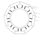
また、図1と図3と図4を参照する。各単一磁極1の巻線作業が完成した後、各単一磁極1の両側の端面に設けた凸縁11と溝12とにより、多数の単一磁極1が互いに連結し、すなわち、各単一磁極1の一端にある凸縁11は他の単一磁極1の一端にある溝12と互いに連結し、図4に示すように、予定数量の単一磁極1を連結すると、予定半径を持つ固定子本体が形成される。
Reference is also made to FIG. 1, FIG. 3 and FIG. After the winding work of each single
なお、図6に示すように、各単一磁極1を互いに連結する際に、単一磁極1の両側の端面に設けた凸縁11の円心aと、溝12の円心bと、円形固定子の円心cとは二等辺三角形を成し、だから、多数の単一磁極1を連結する際には、単一磁極1の数量にも係わらずに連結角度を自在に調整することができると共に、図5に示すように、単一磁極1を円形に組合するときには、必要な数量によって固定子の円心cから等角度に分割することができ、凸縁11の円心aと、溝12の円心bとは円心cから放射する直線に同時に位置することが必要であり、なお、三つの円心が二等辺三角形を成した後、図7に示すように、全体も円形になり、だから、上記ルールに従うと、予定半径を持つモータ固定子本体は完成できる。
As shown in FIG. 6, when the single
また、図8乃至図12に示すのは本発明の他の実施例である。図8は本発明の他の実施例に絶縁部材を組付けたものの分解斜視図である。本実施例では、絶縁部材3の主な部分の寸法は単一磁極1と同様であり、且つ前記単一磁極1の背面に設けた2本の溝13と結合して一体になるために、互いに平行する半円形状柱体31は、図9に示すように、前記絶縁部材3の主な部分の下縁から前記主な部分と垂直して延在する。
FIGS. 8 to 12 show another embodiment of the present invention. FIG. 8 is an exploded perspective view of another embodiment of the present invention in which an insulating member is assembled. In this embodiment, the size of the main part of the
本実施例に係る単一磁極1を円形に組合する際には、図10に示すように、まず、前記絶縁部材3が挿入された単一磁極1を互いに直線に連結して巻線作業を実施し、単一磁極1に銅線2を巻線した後、図11に示すように、円形の固定子に組合することができる。
When the single
また、図12に示すように、前記絶縁部材3の本体の上面の両端には、巻線した後の銅線2の端部を固定するための固定溝32がそれぞれ設けてある。
Also, as shown in FIG. 12, fixing
このように、本発明が、特定の例を参照して説明されたが、それらの例は、説明のためだけのものであり、本発明を限定するものではなく、この分野に通常の知識を有する者には、本発明の精神および範囲を逸脱することなく、ここで開示された実施例に変更、追加、または、削除を施してもよいことがわかる。 Thus, although the present invention has been described with reference to specific examples, the examples are for illustrative purposes only and are not intended to limit the invention, and have ordinary knowledge in the art. Those skilled in the art will recognize that changes, additions, or deletions may be made to the embodiments disclosed herein without departing from the spirit and scope of the present invention.
1 単一磁極 11 凸縁
12 溝 13 溝
2 銅線 3 絶縁部材
31 半円形状柱体 32 固定溝
c モータ固定子の円心 a 凸縁の円心
b 溝の円心
DESCRIPTION OF
Claims (5)
前記単一磁極の両側の端面にはS型連結面が設けてあり、
前記連結面により多数の単一磁極は連結してモータにある固定子の円形な鉄芯の構造になることを特徴とする、
モータ固定子用鉄芯の構造。 Including an E-shaped single pole,
S-type connection surfaces are provided on both end faces of the single magnetic pole,
A plurality of single magnetic poles are connected by the connecting surface to form a circular iron core structure of a stator in the motor,
Structure of iron core for motor stator.
An insulating member is assembled to the single magnetic pole, and the insulating member has a main portion having the same dimensions as the single magnetic pole, and the distant member is provided on two back surfaces of the single magnetic pole. Parallel semi-circular columns for coupling and integration with the grooves are provided, and the semi-circular columns extend perpendicularly to the main portion from the lower edge of the main portion of the insulating member. The fixing groove for fixing the edge part of the electric wire after winding is each provided in the both ends of the upper surface of the main body of the said insulation member, The said of Claim 4 characterized by the above-mentioned. Structure of iron core for motor stator.
Priority Applications (1)
| Application Number | Priority Date | Filing Date | Title |
|---|---|---|---|
| JP2005318512A JP2007129802A (en) | 2005-11-01 | 2005-11-01 | Structure of iron core for motor stator |
Applications Claiming Priority (1)
| Application Number | Priority Date | Filing Date | Title |
|---|---|---|---|
| JP2005318512A JP2007129802A (en) | 2005-11-01 | 2005-11-01 | Structure of iron core for motor stator |
Publications (1)
| Publication Number | Publication Date |
|---|---|
| JP2007129802A true JP2007129802A (en) | 2007-05-24 |
Family
ID=38152003
Family Applications (1)
| Application Number | Title | Priority Date | Filing Date |
|---|---|---|---|
| JP2005318512A Pending JP2007129802A (en) | 2005-11-01 | 2005-11-01 | Structure of iron core for motor stator |
Country Status (1)
| Country | Link |
|---|---|
| JP (1) | JP2007129802A (en) |
Cited By (2)
| Publication number | Priority date | Publication date | Assignee | Title |
|---|---|---|---|---|
| JP2010213496A (en) * | 2009-03-11 | 2010-09-24 | Honda Motor Co Ltd | Stator and motor |
| JP2014036507A (en) * | 2012-08-08 | 2014-02-24 | Denso Corp | Stator |
Citations (4)
| Publication number | Priority date | Publication date | Assignee | Title |
|---|---|---|---|---|
| JPS61124241A (en) * | 1984-11-20 | 1986-06-12 | Matsushita Electric Ind Co Ltd | Stator of inner rotor type small-sized dc motor |
| JPS6333348U (en) * | 1986-08-13 | 1988-03-03 | ||
| JPH0819196A (en) * | 1993-11-08 | 1996-01-19 | Mitsubishi Electric Corp | Rotating electric motor, its manufacture as well as laminated core and its manufacture |
| JP2003324009A (en) * | 2002-04-26 | 2003-11-14 | Mitsubishi Heavy Ind Ltd | Magnetic path forming body method of manufacturing the same, electric motor, transformer, and actuator |
-
2005
- 2005-11-01 JP JP2005318512A patent/JP2007129802A/en active Pending
Patent Citations (5)
| Publication number | Priority date | Publication date | Assignee | Title |
|---|---|---|---|---|
| JPS61124241A (en) * | 1984-11-20 | 1986-06-12 | Matsushita Electric Ind Co Ltd | Stator of inner rotor type small-sized dc motor |
| JPS6333348U (en) * | 1986-08-13 | 1988-03-03 | ||
| JPH0819196A (en) * | 1993-11-08 | 1996-01-19 | Mitsubishi Electric Corp | Rotating electric motor, its manufacture as well as laminated core and its manufacture |
| JPH11220841A (en) * | 1993-11-08 | 1999-08-10 | Mitsubishi Electric Corp | Rotating motor |
| JP2003324009A (en) * | 2002-04-26 | 2003-11-14 | Mitsubishi Heavy Ind Ltd | Magnetic path forming body method of manufacturing the same, electric motor, transformer, and actuator |
Cited By (2)
| Publication number | Priority date | Publication date | Assignee | Title |
|---|---|---|---|---|
| JP2010213496A (en) * | 2009-03-11 | 2010-09-24 | Honda Motor Co Ltd | Stator and motor |
| JP2014036507A (en) * | 2012-08-08 | 2014-02-24 | Denso Corp | Stator |
Similar Documents
| Publication | Publication Date | Title |
|---|---|---|
| US7550892B2 (en) | High slot utilization systems for electric machines | |
| TWI412209B (en) | Insulation bobbin of a stator | |
| US8368263B2 (en) | Universal motor | |
| JP2006109658A (en) | Resolver external wire fixing structure | |
| JP2010004729A (en) | Slotless motor | |
| WO2023024268A1 (en) | Wound core transformer coil winding structure | |
| JP2017112213A (en) | choke coil | |
| JP2007157956A (en) | Switching transformer | |
| JP6423269B2 (en) | Common mode choke coil | |
| JP3189670U (en) | Improved structure of transformer iron core | |
| JP2007129802A (en) | Structure of iron core for motor stator | |
| JP2007014088A (en) | Stator for dynamo-electric machine, dynamo-electric machine, and method of manufacturing stator for dynamo-electric machine | |
| JP6089824B2 (en) | Trance | |
| WO2015180577A1 (en) | Coupling inductor and power converter | |
| JP2007028759A (en) | Centralized power distribution member for motors, manufacturing method for centralized power distribution members, bus bar, and manfuacturing method for bus bars | |
| CN205846882U (en) | A kind of stator core and there is the motor of this stator core | |
| CN208796806U (en) | The board-like flat transformer structure of new copper | |
| CN201360180Y (en) | Plastic packaging motor for straight wind-type AC conditioner | |
| CN208691045U (en) | Field frame assembly | |
| CN204465171U (en) | Stator punching | |
| EP3800652A1 (en) | Inductor core and inductor device | |
| TWI458224B (en) | Motor and coil structure thereof | |
| JP2009044825A (en) | Slotless motor | |
| CN216086273U (en) | Split type stator core structure and disc type motor with same | |
| JPH09168257A (en) | Motor stator with improved suitablility to be assembled |
Legal Events
| Date | Code | Title | Description |
|---|---|---|---|
| A131 | Notification of reasons for refusal |
Free format text: JAPANESE INTERMEDIATE CODE: A131 Effective date: 20080108 |
|
| A02 | Decision of refusal |
Free format text: JAPANESE INTERMEDIATE CODE: A02 Effective date: 20080617 |