JP2007127245A - Noise control device and image-forming device - Google Patents
Noise control device and image-forming device Download PDFInfo
- Publication number
- JP2007127245A JP2007127245A JP2005322381A JP2005322381A JP2007127245A JP 2007127245 A JP2007127245 A JP 2007127245A JP 2005322381 A JP2005322381 A JP 2005322381A JP 2005322381 A JP2005322381 A JP 2005322381A JP 2007127245 A JP2007127245 A JP 2007127245A
- Authority
- JP
- Japan
- Prior art keywords
- noise
- sound
- noise suppression
- exhaust duct
- suppression device
- Prior art date
- Legal status (The legal status is an assumption and is not a legal conclusion. Google has not performed a legal analysis and makes no representation as to the accuracy of the status listed.)
- Pending
Links
Images


Abstract
Description
本発明は、複写機、プリンター、ファクシミリ等の画像形成装置に好適な、排気経路の騒音を抑制する抑制低減装置に関するものである。 The present invention relates to a suppression / reduction device suitable for an image forming apparatus such as a copying machine, a printer, and a facsimile, for suppressing noise in an exhaust path.
従来、複写機、プリンター、ファクシミリ、スキャナー等の画像形成及び画像読取り装置では、装置内部の温度上昇を防止するため、または装置内部で発生するオゾンを機外に排出するため、冷却ファンが用いられている。 Conventionally, in image forming and image reading apparatuses such as copying machines, printers, facsimiles, scanners, etc., cooling fans have been used to prevent temperature rise inside the apparatus or to discharge ozone generated inside the apparatus outside the apparatus. ing.
例えば、複写機は、内部の高温発生部位として定着器やスキャナーが存在し、これら高温発生部位からの熱を本体開口部に設けた冷却ファンにより排気流として本体外部に排出していた。 For example, a copying machine includes a fixing device and a scanner as an internal high temperature generation site, and heat from the high temperature generation site is exhausted to the outside of the main body as an exhaust flow by a cooling fan provided in the main body opening.
また装置内部でオゾンが発生する転写部・分離部の近傍にオゾン排出用ファンが設けられ、本体外部にオゾンを排出していた。 In addition, an ozone discharge fan is provided in the vicinity of the transfer / separation unit where ozone is generated inside the apparatus, and ozone is discharged outside the main body.
この冷却ファン、オゾン排出用ファンは高温発生部位もしくはオゾン発生部位から装置外部へ排気経路を形成するためにダクトを配置している。 In the cooling fan and the ozone discharge fan, a duct is disposed to form an exhaust path from the high temperature generation site or the ozone generation site to the outside of the apparatus.
前述の従来例において、冷却ファン、オゾン排出用ファンは複写機の筐体表面近傍に設置されていることから、冷却ファン、オゾン排出用ファンの動作時に発生する騒音がそのまま装置から機外へ放射されてしまい、装置本体近辺にいる人の不快感を招くものであった。 In the above-described conventional example, the cooling fan and the ozone discharge fan are installed near the surface of the copying machine casing, so that the noise generated during the operation of the cooling fan and the ozone discharge fan is radiated from the apparatus to the outside as it is. This has caused discomfort for people in the vicinity of the apparatus main body.
また、複数の高温発生部位の温度状況が一様であるとは限らず、さらに複写機本体形状の制約から、それぞれの高温発生部位に対する排気ダクトの排気流路の形状も一様にできるとは限らない。そのため、それぞれの高温発生部位における冷却効率に差が生じる。このとき、本体内で最高温度を示す測定点を基準にして冷却ファンの風量を決定する必要があるため、高温発生部位によっては必要以上の冷却が施されていることになり、冷却ファンの騒音増大の原因となっていた。オゾン排出用ファンにおいても同様の問題が生じていた。 In addition, the temperature conditions of a plurality of high temperature generating parts are not necessarily uniform, and the shape of the exhaust duct of the exhaust duct for each high temperature generating part can be made uniform due to restrictions on the shape of the copying machine main body. Not exclusively. Therefore, a difference arises in the cooling efficiency in each high temperature generating part. At this time, since it is necessary to determine the air flow of the cooling fan based on the measurement point showing the maximum temperature in the main body, the cooling fan is noisy depending on the part where the high temperature is generated. It was the cause of the increase. A similar problem has occurred in the ozone discharge fan.
また、排気ダクトを介在して、複写機の内部の音、例えば駆動音などを複写機外部へ伝達することもよくあった。 Also, the sound inside the copying machine, such as driving sound, is often transmitted to the outside of the copying machine via an exhaust duct.
これらの問題の対策として、排気ダクト内の音を検知し、その音に対して逆位相の音を排気ダクト内において出力することによって、排気ダクト内の音を低減させる技術(アクティブノイズコントロール)がある。このアクティブノイズコントロールを使えばダクト内において冷却ファン、オゾン排気ファンの音を小さくすることができるため、結果として複写機から機外へ放射される音を小さくすることができる。この技術については特許文献1ないし4に記載されている。 As a countermeasure against these problems, there is a technology (active noise control) that detects sound in the exhaust duct and outputs sound in the exhaust duct in the opposite phase to that sound, thereby reducing the sound in the exhaust duct. is there. If this active noise control is used, the noise of the cooling fan and the ozone exhaust fan can be reduced in the duct, and as a result, the sound radiated from the copying machine to the outside can be reduced. This technique is described in Patent Documents 1 to 4.
しかし、冷却ファン、オゾン排気ファンの音の大きさは常に同じではなくて排気ダクト内に設けたフィルターやファンの劣化などにより変化する可能性がある。その結果、その音の周波数毎の音圧レベルも変化し、排気ダクト内の音響モードが変化する可能性がある。そして、排気ダクト内の音を正確に検知できずアクティブノイズコントロールによって騒音低減ができなくなる可能性がある。 However, the loudness of the cooling fan and the ozone exhaust fan is not always the same, and may change due to deterioration of a filter or fan provided in the exhaust duct. As a result, the sound pressure level for each frequency of the sound also changes, and the acoustic mode in the exhaust duct may change. In addition, the sound in the exhaust duct cannot be accurately detected, and there is a possibility that noise cannot be reduced by active noise control.
本発明は、このような状況のもとでなされたもので、排気経路を介して装置外へ放射される騒音を経時的に安定して抑えることのできる、騒音抑制装置および画像形成装置を提供することを課題とするものである。
前記課題を解決するため、本発明では、騒音抑制装置を次の(1)のとおりに構成する。 In order to solve the above problems, in the present invention, a noise suppression device is configured as described in (1) below.
(1)排気経路に設けられ、前記排気経路における騒音を検知するコントロールマイクと、前記コントロールマイクで検知された音に応じてその音の逆位相の音を排気ダクト内において出力する出力部を有するアクティブノイズコントロールシステムで騒音を抑制する騒音抑制装置であって、
前記排気経路に配置したコントロールマイクの騒音検知位置を変更する検知位置変更手段を備えた騒音抑制装置。
(1) A control microphone that is provided in the exhaust path and detects noise in the exhaust path, and an output unit that outputs a sound having an opposite phase to the sound detected by the control microphone in the exhaust duct. A noise suppression device that suppresses noise with an active noise control system,
A noise suppression device comprising detection position changing means for changing a noise detection position of a control microphone arranged in the exhaust path.
本発明によれば、騒音を経時的に安定して抑えることができる。 According to the present invention, noise can be stably suppressed over time.
以下本発明を実施するための最良の形態を、画像形成装置の実施例により詳しく説明する。 Hereinafter, the best mode for carrying out the present invention will be described in detail with reference to an embodiment of an image forming apparatus.
図1は、実施例1である“騒音抑制装置を搭載した画像形成装置”の構成を示す断面図である。圧板2下の原稿台ガラスに載置された原稿は、原稿読取り部3によって読み取られる。そして、感光ドラム4上に潜像が形成される。潜像は現像部5によってトナー像に画像形成される。カセット6に載置された転写紙Pは搬送パス7を経由して転写・分離部8へと搬送される。転写・分離部8で、前記画像形成されたトナー像は転写紙Pへ転写される。そして搬送部9、定着装置10を経由して画像形成装置1の外部へ排出される。
FIG. 1 is a cross-sectional view illustrating a configuration of an “image forming apparatus equipped with a noise suppression device” according to a first embodiment. The document placed on the platen glass under the pressure plate 2 is read by the document reading unit 3. Then, a latent image is formed on the photosensitive drum 4. The latent image is formed into a toner image by the developing
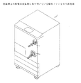
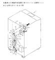
図2、図3は、画像形成装置1に取り付けられている冷却ファンおよび排気ダクトを示し、エアフロー系統を示した画像形成装置1の斜視図である。 2 and 3 are perspective views of the image forming apparatus 1 showing a cooling fan and an exhaust duct attached to the image forming apparatus 1 and showing an airflow system.
画像形成装置1へ取り込まれるエアは、図2に示すように画像形成装置1の前面に配置された吸引ファン11、12によって、エアが画像形成装置1の内部へ吸引される。そして、画像形成装置1の内部で発生している熱およびオゾンを図3に示すように、排気ファン13、14および排気ダクト15によって開口部15−dより画像形成装置1の外部へ排出している。なお、吸引ファンは装置前面でなくとも側面或いは背面でも良い。
The air taken into the image forming apparatus 1 is sucked into the image forming apparatus 1 by
排気ダクト15は、画像形成装置1の後側板16に取り付けられ、2方向からエアが流れる排気ダクト15−a、15−bが合流し、排気ダクト15−cによって画像形成装置1の下方へとエアを流している。
The
排気ダクト15の材料はABSなどの樹脂が使われている。排気ダクト15の厚みは排気ファン13、14の振動が伝わらない程度の厚み、例えば最低5mmの厚みは必要である。
The
排気ダクト15−cの途中には本実施例の特徴をなす能動消音システム(アクティブノイズコントロールシステム)17が配置されている。排気ダクト15−cの内部を伝わって画像形成装置1の外部へ放射される吸引ファン11、12および排気ファン13、14から発生する音および画像形成装置1内部で発生する駆動音などを能動消音システム17によって消音している。
In the middle of the exhaust duct 15-c, an active silencing system (active noise control system) 17 that characterizes the present embodiment is arranged. Active silencing of the sound generated from the
次にこの能動消音システム17の詳細について説明する。
Next, details of the
図4は能動消音システム17の断面図および電気ブロック図を示したものである。まず排気ダクト15−c内部の音を排気ダクト15−cの内壁面にコントロールマイク18の音の検知面18−aが沿うように配置したコントロールマイク18によって検出する。その音をアンプ19によって増幅し、AD変換器(A.D.C)20によって音をデジタル信号化する。そして適応フィルター:W(21)によって、信号の位相を反転してDA変換器(D.A.C)22によって信号をアナログ化し、アンプ23によって増幅後、2次音源スピーカ24によって排気ダクト15−cの中へ音を付加している。つまりコントロールマイク18で検知した音と逆位相の音を2次音源スピーカ24によって排気ダクト15−c内に放射し、排気ダクト15−c内の音を音の干渉によって消音している。
FIG. 4 shows a cross-sectional view and an electrical block diagram of the
2次音源スピーカ24の周囲にはスピーカ24を取り囲んでスピーカカバー24−aが設けられている。これは2次音源スピーカ24の出力が排気ダクト15−c内に向かうようにするための構成である。
A speaker cover 24-a is provided around the secondary
2次音源スピーカ24から放射された音は元の音と重なって排気ダクト15−cの内壁面に音の検知面がくるように配置したエラーマイク25によって検出される。エラーマイク25によって検出された音はアンプ26によって増幅後、AD変換器(A.D.C)27によってデジタル信号化されLMS(Least Mean Square)演算部28に入る。LMS演算部28ではエラーマイク25で検出された音が最小化するように演算処理がされ、その結果を適応フィルター:W(21)に入力し、2次音源スピーカ24から放射する音を決める。つまり、エラーマイク25の音が最小化するようにフィードバック制御を行っている。
The sound radiated from the secondary
誤差経路補償フィルター:C(29)は、2次音源スピーカ24からエラーマイク25に至る伝達特性を模擬した回路である。誤差経路補償フィルター:C(29)は、コントロールマイク18の検出信号とエラーマイク25での検出信号のタイミングを合わせるためにLMS演算部28において演算を行い2次音源スピーカ24から放出する音の調整を行っている。
The error path compensation filter C (29) is a circuit that simulates transfer characteristics from the secondary
また、ハウリング補償フィルター30に示す経路は、2次音源スピーカ24からの音がコントロールマイク18にフィードバックする経路であるためハウリングの原因となる。これを防止するためにハウリング補償フィルター30を配置し、ハウリングを防止している。
Further, the path shown in the
次に能動消音システム17のコントロールマイク18の動作について説明する。
Next, the operation of the
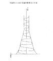
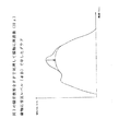
まず排気ダクト15−c内部の音を検知する。図6は排気ダクト15−cの内部の音圧レベルを模式的に示した音響モードを示した模式図である。図示のとおり、排気ダクト15−c内の音圧レベルは場所によって異なる。腹の位置は音圧レベルが大きくなり、節の部分は音圧レベルが小さくなる。この音響モードは音の周波数によっても異なるが、この場合は例えば、500Hz〜3000Hzまでの音圧レベルのオーバーオールで音響モードが形成されていると考えて良い。 First, the sound inside the exhaust duct 15-c is detected. FIG. 6 is a schematic diagram showing an acoustic mode schematically showing the sound pressure level inside the exhaust duct 15-c. As illustrated, the sound pressure level in the exhaust duct 15-c varies depending on the location. The sound pressure level is increased at the belly position, and the sound pressure level is decreased at the nodes. Although this acoustic mode differs depending on the sound frequency, in this case, for example, it may be considered that the acoustic mode is formed with an overall sound pressure level of 500 Hz to 3000 Hz.
このため、排気ダクト15−c内部の腹位置を探査すべくコントロールマイク18を走査させる必要がある。
For this reason, it is necessary to scan the
コントロールマイク18の走査の手段としては図3、図4に示すように排気ダクト15−cの壁面に角穴15−eが明けられ、この上にスムーズに直線移動可能なアキュライドレール31を固定する。アキュライドレール31の上にはL字状のマイク支持板32が固定され、その上にコントロールマイク18を固定している。マイク支持板32はステッピングモータ33の出力軸に固定しているプーリー34と従動回転する従動プーリー35の間に掛けられたワイヤー36に固定されている。これによりワイヤー36の移動に同期してマイク支持板32も移動するようになっている。
As a means for scanning by the
コントロールマイク18は角穴15−eより排気ダクト15−c内部の音を検知するが、コントロールマイク18以外の角穴15−eから排気ダクト15−c内部の音が外部に漏れる。これを防止するため、マイク支持板32とアキュライドレール31の間に蛇腹状の防音部材(不図示)が設けられ、コントロールマイク18が移動してもその他の角穴15−eは塞がれている。
The
また、図3に示すように、ステッピングモータ33、コントロールマイク18、2次音源スピーカ24、エラーマイク25は、画像形成装置1の内部に取り付いている能動消音システム17のコントローラ37に信号伝達ができるようにケーブル結線がなされている。
Further, as shown in FIG. 3, the stepping
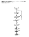
次に能動消音システム17のコントロールマイク18の動作手順を図5のフローチャートによって説明する。この動作手順は、コントローラ37により処理される。
Next, the operation procedure of the
まずコントロールマイク18(Cマイク)を前述したように排気ダクト15−c内の騒音レベルの最大値を走査すべく移動させる(ステップ1)。 First, as described above, the control microphone 18 (C microphone) is moved to scan the maximum value of the noise level in the exhaust duct 15-c (step 1).
コントロールマイク18の走査と同時に排気ダクト15−c内の音圧レベルをコントローラ37にて計算する(ステップ2)。
Simultaneously with the scanning of the
排気ダクト15−c内でコントロールマイク18の移動可能部分をひと通り走査したら走査した排気ダクト15−c内で最大の音圧レベルの部分を検出し、その部分に移動して、コントロールマイク18の位置を固定する(ステップ3)。
When the movable part of the
次に前記排気ダクト15−c内の音圧レベルの最大部分において図4に示すアンプ19を調整し、排気ダクト15−c内の音圧レベルをアンプ19で増幅可能になるまで調整する(ステップ4)。
Next, the
次に図4に示す2次音源スピーカ24より全周波数帯の音がすべて入っている音(いわゆるホワイトノイズ)を出力し、エラーマイク25の検知出力が最大になるように2次音源スピーカ24のアンプ23を調整する。その状態で、ホワイトノイズを2次音源スピーカ24より出力する(いわゆる同定)(ステップ5)。
Next, the secondary
同定終了後、前記説明した誤差経路補償フィルター29に同定値Cを入れ、保存する。(ステップ6)その後、能動消音システム17(ANC)の適応を開始する(ステップ7)。
After the identification is completed, the identification value C is input to the error
図7、図8は能動消音システム17を排気ダクト15−cで作動させることにより得られる騒音低減の効果を示した図である。
FIGS. 7 and 8 are views showing the noise reduction effect obtained by operating the active silencing
図7は横軸に時間(S)縦軸に騒音波形(図4のエラーマイク25で検出した電圧波形(V))を示している。 図8は、図7の騒音波形をFFT処理(高速フーリエ変換)して、横軸に周波数(Hz)縦軸に音圧レベル(dB)を示したグラフである。
FIG. 7 shows time (S) on the horizontal axis and noise waveform (voltage waveform (V) detected by the
図7に示すように能動消音システム17を作動させると時間経過とともに騒音波形(V)は小さくなる。また図8に示すように所定周波数の音圧レベル(dB)が矢印の方向に減少する。すなわち、排気ダクト15−c内の音圧レベルの最大値の部分にコントロールマイク18を位置させることにより、図7、図8に示す騒音低減の効果が大きくなる。
As shown in FIG. 7, when the active silencing
以上説明したように本実施例によれば、吸気ファン、冷却ファン動作時に発生する騒音が直接装置本体の開口部から放射されることがなくなり、低騒音化を実現することができる。 As described above, according to the present embodiment, noise generated during operation of the intake fan and the cooling fan is not directly radiated from the opening of the apparatus main body, and noise reduction can be realized.
さらに吸気ファン、冷却ファンの劣化などにより、もしくは冷却ファン、吸気ファンと装置外部の間に設けたオゾンフィルターの劣化などにより、経時的に画像形成装置から放射される音質が変化した場合でも、低騒音化を達成できる。即ち、音のモードを検出し最適なマイク位置で音を検出することによりさらなる低騒音化を実現できる。 Even if the sound quality radiated from the image forming device changes over time due to deterioration of the intake fan and cooling fan, or deterioration of the ozone filter provided between the cooling fan and intake fan and the outside of the device, etc. Noise reduction can be achieved. That is, further noise reduction can be realized by detecting the sound mode and detecting the sound at the optimum microphone position.
次に実施例2である“画像形成装置”について、図9を用いて説明をする。
なお、実施例1と同一の部品は同一符号を記し、説明を省略する。
Next, an “image forming apparatus” that is Embodiment 2 will be described with reference to FIG.
The same parts as those in the first embodiment are denoted by the same reference numerals, and the description thereof is omitted.
図9は実施例2における能動消音システム48を示した排気ダクト15−cの断面図および電気系統図である。
実施例1と異なる部分は、実施例1では1つのコントロールマイク18を移動して排気ダクト15−c内の音圧レベルの最大部分を見つけていたのに対して本実施例では図9に示すようにコントロールマイク46−a〜46−fを複数配置している。47はコントロールマイク46−a〜46−fを排気ダクト15−cに取り付ける取り付け板である。
FIG. 9 is a cross-sectional view and an electrical system diagram of the exhaust duct 15-c showing the active silencing
The difference from the first embodiment is that, in the first embodiment, one
コントロールマイク46−a〜46−fで順次、排気ダクト15−c内の音圧レベルを計測して、音圧レベルの最大値を計測したコントロールマイクをマイク46−a〜46−fから1つ選定する。その後は選定したコントロールマイクで、図5に示す実施例1の41〜45の動作をして能動消音システム48を動作させ、排気ダクト15−c内の騒音を下げる。
The control microphones 46-a to 46-f sequentially measure the sound pressure level in the exhaust duct 15-c, and one of the control microphones 46-a to 46-f that measures the maximum value of the sound pressure level is measured. Select. Thereafter, with the selected control microphone, the operations 41 to 45 of the first embodiment shown in FIG. 5 are performed to activate the active silencing
以上説明したように、本実施例によっても、実施例1と同様の効果を得ることができる。本実施例では、角穴や防音部材から音が漏れることがなく、また可動部分がないので構成が簡単になる。 As described above, this embodiment can provide the same effects as those of the first embodiment. In this embodiment, sound does not leak from the square hole or the soundproof member, and the structure is simple because there are no movable parts.
(変形)
騒音検知位置の変更は、頻繁に行う必要がないので、手動で変更するようにしてもよい。このようにすることにより装置の構成を簡単にすることができる。また、手動で変更する場合には、音圧レベルの最大位置に限らず、耳障りとならない音質が得られる位置に騒音検知位置を変更するようにしてもよい。この場合は、音圧レベル検知装置を特に必要としない利点がある。
(Deformation)
Since it is not necessary to change the noise detection position frequently, it may be changed manually. By doing so, the configuration of the apparatus can be simplified. Moreover, when changing manually, you may make it change a noise detection position not only to the maximum position of a sound pressure level but to the position where the sound quality which does not become harsh is obtained. In this case, there is an advantage that a sound pressure level detection device is not particularly required.
15 騒音伝達経路
18 コントロールマイク
24 2次音源スピーカ
15
Claims (6)
前記排気経路に配置したコントロールマイクの騒音検知位置を変更する検知位置変更手段を備えたことを特徴とする騒音抑制装置。 An active noise control having a control microphone provided in the exhaust path and detecting noise in the exhaust path, and an output unit that outputs a sound in an opposite phase of the sound in the exhaust duct according to the sound detected by the control microphone A noise suppression device for suppressing noise in a system,
A noise suppression device comprising detection position changing means for changing a noise detection position of a control microphone arranged in the exhaust path.
前記検知位置変更手段は、前記コントロールマイクを前記排気経路に沿って移動することにより検知位置を変更するものであることを特徴とする騒音抑制装置。 The noise suppression device according to claim 1,
The noise suppression device, wherein the detection position changing means changes the detection position by moving the control microphone along the exhaust path.
前記検知位置変更手段は、前記排気経路に沿って配置した複数のコントロールマイクから所要のマイクを選択することにより検知位置を変更するものであることを特徴とする騒音抑制装置。 The noise suppression device according to claim 1,
The noise suppression device according to claim 1, wherein the detection position changing means changes a detection position by selecting a required microphone from a plurality of control microphones arranged along the exhaust path.
前記コントロールマイクからの信号が最大になるように、前記検知位置変更手段を制御する制御手段を備えたことを特徴とする騒音抑制装置。 The noise suppression device according to any one of claims 1 to 3,
A noise suppression apparatus comprising control means for controlling the detection position changing means so that a signal from the control microphone becomes maximum.
前記検知位置変更手段は手動で変更可能な構成であることを特徴とする騒音抑制装置。 The noise suppression device according to any one of claims 1 to 3,
The noise suppression device according to claim 1, wherein the detection position changing means is manually changeable.
Priority Applications (1)
| Application Number | Priority Date | Filing Date | Title |
|---|---|---|---|
| JP2005322381A JP2007127245A (en) | 2005-11-07 | 2005-11-07 | Noise control device and image-forming device |
Applications Claiming Priority (1)
| Application Number | Priority Date | Filing Date | Title |
|---|---|---|---|
| JP2005322381A JP2007127245A (en) | 2005-11-07 | 2005-11-07 | Noise control device and image-forming device |
Publications (2)
| Publication Number | Publication Date |
|---|---|
| JP2007127245A true JP2007127245A (en) | 2007-05-24 |
| JP2007127245A5 JP2007127245A5 (en) | 2008-12-25 |
Family
ID=38150057
Family Applications (1)
| Application Number | Title | Priority Date | Filing Date |
|---|---|---|---|
| JP2005322381A Pending JP2007127245A (en) | 2005-11-07 | 2005-11-07 | Noise control device and image-forming device |
Country Status (1)
| Country | Link |
|---|---|
| JP (1) | JP2007127245A (en) |
Cited By (4)
| Publication number | Priority date | Publication date | Assignee | Title |
|---|---|---|---|---|
| JP2009169250A (en) * | 2008-01-18 | 2009-07-30 | Toshiba Tec Corp | Status management device and status management method |
| JP2009205121A (en) * | 2008-01-30 | 2009-09-10 | Ricoh Co Ltd | Image forming apparatus |
| WO2013114807A1 (en) * | 2012-02-03 | 2013-08-08 | 三菱電機株式会社 | Active noise control device |
| JP2014177087A (en) * | 2013-03-15 | 2014-09-25 | Ricoh Co Ltd | Electronic apparatus, information processing system, and program |
Citations (8)
| Publication number | Priority date | Publication date | Assignee | Title |
|---|---|---|---|---|
| JPH0561479A (en) * | 1991-08-30 | 1993-03-12 | Nissan Motor Co Ltd | Active type noise controller |
| JPH05333874A (en) * | 1992-01-13 | 1993-12-17 | Fujitsu Ltd | Duct noise eliminating device |
| JPH07168585A (en) * | 1993-12-10 | 1995-07-04 | Fujitsu Ltd | Active noise control device |
| JPH10254457A (en) * | 1997-03-11 | 1998-09-25 | Isuzu Motors Ltd | Reducing method of noise within vehicle compartment and device therefor |
| JP2000322066A (en) * | 1999-03-09 | 2000-11-24 | Honda Motor Co Ltd | Active noise control device |
| JP2002311763A (en) * | 2001-04-10 | 2002-10-25 | Fuji Xerox Co Ltd | Image forming device |
| JP2002328681A (en) * | 2001-04-27 | 2002-11-15 | Fuji Xerox Co Ltd | Active noise control device |
| JP2004116503A (en) * | 2002-09-25 | 2004-04-15 | Shizuoka Prefecture | Duct with acoustic impedance adjusting mechanism, and electronic silencing system applying the same |
-
2005
- 2005-11-07 JP JP2005322381A patent/JP2007127245A/en active Pending
Patent Citations (8)
| Publication number | Priority date | Publication date | Assignee | Title |
|---|---|---|---|---|
| JPH0561479A (en) * | 1991-08-30 | 1993-03-12 | Nissan Motor Co Ltd | Active type noise controller |
| JPH05333874A (en) * | 1992-01-13 | 1993-12-17 | Fujitsu Ltd | Duct noise eliminating device |
| JPH07168585A (en) * | 1993-12-10 | 1995-07-04 | Fujitsu Ltd | Active noise control device |
| JPH10254457A (en) * | 1997-03-11 | 1998-09-25 | Isuzu Motors Ltd | Reducing method of noise within vehicle compartment and device therefor |
| JP2000322066A (en) * | 1999-03-09 | 2000-11-24 | Honda Motor Co Ltd | Active noise control device |
| JP2002311763A (en) * | 2001-04-10 | 2002-10-25 | Fuji Xerox Co Ltd | Image forming device |
| JP2002328681A (en) * | 2001-04-27 | 2002-11-15 | Fuji Xerox Co Ltd | Active noise control device |
| JP2004116503A (en) * | 2002-09-25 | 2004-04-15 | Shizuoka Prefecture | Duct with acoustic impedance adjusting mechanism, and electronic silencing system applying the same |
Cited By (4)
| Publication number | Priority date | Publication date | Assignee | Title |
|---|---|---|---|---|
| JP2009169250A (en) * | 2008-01-18 | 2009-07-30 | Toshiba Tec Corp | Status management device and status management method |
| JP2009205121A (en) * | 2008-01-30 | 2009-09-10 | Ricoh Co Ltd | Image forming apparatus |
| WO2013114807A1 (en) * | 2012-02-03 | 2013-08-08 | 三菱電機株式会社 | Active noise control device |
| JP2014177087A (en) * | 2013-03-15 | 2014-09-25 | Ricoh Co Ltd | Electronic apparatus, information processing system, and program |
Similar Documents
| Publication | Publication Date | Title |
|---|---|---|
| US7995769B2 (en) | Sound control apparatus of image forming apparatus | |
| JP2530779B2 (en) | Noise reduction device | |
| JPH05249983A (en) | Image forming device | |
| JP2007127245A (en) | Noise control device and image-forming device | |
| JP3039342B2 (en) | Silencer and muffling method for image forming apparatus | |
| JPH068581A (en) | Noise preventing mechanism of image forming apparatus | |
| JP2006118422A (en) | Fan noise reducing device in electronic apparatus | |
| JP4078368B2 (en) | Silencer and image forming apparatus | |
| JP4302074B2 (en) | Active silencer | |
| JPH08338224A (en) | Noise reducing device for enclosed type engine | |
| JP5110941B2 (en) | Sound suppression apparatus and image forming apparatus having the same | |
| JP2007126983A (en) | Drive device of electric fan | |
| JP2007121827A (en) | Active silencer | |
| JP3496271B2 (en) | Vibration parts feeder device | |
| CN104749903B (en) | Active noise elimination device and lithography equipment | |
| JP2006323176A (en) | Noise control system and noise control method | |
| JP2001356777A (en) | Active noise eliminating device | |
| JPH09258741A (en) | Active muffler | |
| JP2597565Y2 (en) | Muffler using movable noise canceling speaker | |
| JP3621406B2 (en) | Image forming apparatus | |
| JPH0772873A (en) | Active muffler | |
| JP3148983B2 (en) | Effective electronic silencer for noise sources requiring heat exchange | |
| JP2009118996A (en) | Vacuum cleaner | |
| JP2000098828A (en) | Active type noise controller for image forming device | |
| JPH07160272A (en) | Noise control device |
Legal Events
| Date | Code | Title | Description |
|---|---|---|---|
| A521 | Written amendment |
Free format text: JAPANESE INTERMEDIATE CODE: A523 Effective date: 20081107 |
|
| A621 | Written request for application examination |
Free format text: JAPANESE INTERMEDIATE CODE: A621 Effective date: 20081107 |
|
| A977 | Report on retrieval |
Free format text: JAPANESE INTERMEDIATE CODE: A971007 Effective date: 20110218 |
|
| A131 | Notification of reasons for refusal |
Free format text: JAPANESE INTERMEDIATE CODE: A131 Effective date: 20110614 |
|
| A02 | Decision of refusal |
Free format text: JAPANESE INTERMEDIATE CODE: A02 Effective date: 20111108 |