JP2007125571A - Method for joining members, structure of joined members, and fuel tank - Google Patents
Method for joining members, structure of joined members, and fuel tank Download PDFInfo
- Publication number
- JP2007125571A JP2007125571A JP2005318831A JP2005318831A JP2007125571A JP 2007125571 A JP2007125571 A JP 2007125571A JP 2005318831 A JP2005318831 A JP 2005318831A JP 2005318831 A JP2005318831 A JP 2005318831A JP 2007125571 A JP2007125571 A JP 2007125571A
- Authority
- JP
- Japan
- Prior art keywords
- projection
- welding
- plate
- fuel tank
- base
- Prior art date
- Legal status (The legal status is an assumption and is not a legal conclusion. Google has not performed a legal analysis and makes no representation as to the accuracy of the status listed.)
- Pending
Links
Images


Abstract
Description
本発明は、部材接合方法、部材接合構造体および燃料タンクに係り、特に、プロジェクション溶接に適する突起を容易に形成することができる部材接合方法、部材接合構造体および燃料タンクに関する。 The present invention relates to a member joining method, a member joining structure, and a fuel tank, and more particularly to a member joining method, a member joining structure, and a fuel tank capable of easily forming a projection suitable for projection welding.
従来から、シール性を要する接合箇所に使用される抵抗溶接の一種として、被溶接材に突起(プロジェクション)を設け、その上下に配置した溶接用の電極によって通電加圧することで、前記突起部に熱および圧力を集中させて溶融あるいは塑性流動を生じさせて接合するプロジェクション溶接が知られている。抵抗溶接とは、接合する金属材料を重ね合わせた状態、または突き合わせた状態で、被溶接材料に数千〜数万アンペアの電流を流し、この際に得られる抵抗発熱によって被溶接部材を溶融しながら加圧して接合する方法の総称である。また、特に、円環状に施されるプロジェクション溶接は、リングプロジェクション溶接と呼ばれる。 Conventionally, as a type of resistance welding used for joints that require a sealing property, a projection is provided on the material to be welded, and energized and pressurized by welding electrodes arranged above and below the projection, Projection welding is known in which heat and pressure are concentrated to cause melting or plastic flow to join. Resistance welding is a state in which metal materials to be joined are overlapped or butted together, and a current of several thousand to several tens of thousands of amperes is passed through the materials to be welded. It is a general term for the method of joining under pressure. In particular, projection welding performed in an annular shape is called ring projection welding.
特許文献1には、リングプロジェクション溶接を施す際に、前記プロジェクションが設けられる被溶接部材の厚さをt(mm)とした場合に、前記プロジェクションの頂部の幅を、t(mm)以上2t(mm)以下に形成した接合方法が開示されている。該接合方法によれば、前記プロジェクションの頂部の幅がt(mm)より狭い場合に比して、抵抗発熱による過度の発熱が抑えられてプロジェクションの溶融飛散を防ぐことが可能となるので、例えば、通常の鋼板より電気抵抗の大きなステンレス鋼に適用した場合においても良好なリングプロジェクション溶接を行うことができるようになる。
被溶接材にプロジェクションを形成する方法としては、従来から、凸部を有する金型を被溶接材の裏側から押し当てる方法が知られるが、この方法では、プロジェクション先端部における相手方部材との接触面積が大きくなりやすい。このため、大径のリングプロジェクション溶接においては、電流が分散して良好な接合が難しくなるという課題があった。また、上記特許文献1に記載されるプロジェクションのように、その形状を所定の寸法に正確に形成するためには、切削加工等を施す必要が生じるので、製造工程が増大するという課題があった。
As a method of forming a projection on a material to be welded, conventionally, a method of pressing a mold having a convex portion from the back side of the material to be welded is known, but in this method, the contact area of the projection tip with the counterpart member Tends to grow. For this reason, in the large-diameter ring projection welding, there is a problem that current is dispersed and it becomes difficult to perform good joining. In addition, as in the projection described in the above-mentioned
本発明の目的は、上記した従来技術の課題を解決し、プロジェクション溶接に適する突起を容易に形成することができる部材接合方法、部材接合構造体および燃料タンクを提供することにある。 An object of the present invention is to provide a member joining method, a member joining structure, and a fuel tank that can solve the above-described problems of the prior art and can easily form protrusions suitable for projection welding.
前記した目的を達成するために、本発明は、板状部を有する2つの部材をプロジェクション溶接で接合する部材接合方法において、一方側の部材の板状部の端部を溶接面側に湾曲させて突起を形成する工程と、前記端部を他方の部材の板状部に重ね合わせる工程と、前記2つの部材を溶接用の電極で狭持する工程と、前記2つの部材を前記電極で通電加圧することによってプロジェクション溶接を行う工程とを含むようにした点に第1の特徴がある。 In order to achieve the above-described object, the present invention provides a method for joining two members having a plate-like portion by projection welding, wherein the end of the plate-like portion of one member is curved toward the welding surface side. Forming a protrusion, superimposing the end portion on the plate-like portion of the other member, sandwiching the two members with welding electrodes, and energizing the two members with the electrodes. The first feature is that it includes a step of performing projection welding by applying pressure.
また、板状部を有する2つの部材をプロジェクション溶接で接合する部材接合構造体において、一方側の部材の板状部の端部を溶接面側に湾曲させて形成された突起と、前記突起を他方側の部材の板状部に当接し、通電加圧によって形成されたプロジェクション溶接部とを具備するようにした点に第2の特徴がある。 Further, in a member joint structure for joining two members having a plate-like portion by projection welding, a protrusion formed by curving an end of the plate-like portion of one member on the welding surface side, and the protrusion A second feature is that it includes a projection welded portion that is in contact with the plate-like portion of the member on the other side and is formed by energization and pressurization.
さらに、燃料タンクの開口部から燃料ポンプユニットを収容するようにした燃料タンクにおいて、プレス加工によって周縁部の端部を溶接面側に湾曲させて突起を形成した略円環状のベース部材を具備し、前記端部をプロジェクションとして、前記燃料タンクの壁面に前記ベース部材をリングプロジェクション溶接によって接合し、前記ベース部材に前記燃料ポンプユニットの端部を嵌合固定するようにした点に第3の特徴がある。 Furthermore, the fuel tank is configured to receive the fuel pump unit from the opening of the fuel tank, and includes a substantially annular base member having a protrusion formed by curving the end of the peripheral edge toward the welding surface by pressing. The third feature is that the end is a projection, the base member is joined to the wall of the fuel tank by ring projection welding, and the end of the fuel pump unit is fitted and fixed to the base member. There is.
請求項1の発明によれば、プロジェクションとなる突起を、部材を湾曲させる工程によって形成することができるので、製造工程を増大することなく、所定のプロジェクションを容易に形成できる部材接合方法が得られる。また、切削加工等を行うことなく、大径のリングプロジェクション溶接等に適した、頂部が鋭利な形状のプロジェクションを得ることができるようになる。 According to the first aspect of the present invention, since the projection to be a projection can be formed by a step of bending the member, a member joining method capable of easily forming a predetermined projection without increasing the manufacturing process is obtained. . In addition, it is possible to obtain a projection having a sharp shape suitable for large-diameter ring projection welding or the like without performing cutting or the like.
請求項2の発明によれば、プロジェクションとなる突起を、部材を湾曲させる加工によって形成することができるので、製造工程を増大することなく、所定のプロジェクションを容易に形成できる部材接合構造体が得られる。また、切削加工等を行うことなく、大径のリングプロジェクション溶接等に適した、頂部が鋭利な形状のプロジェクションを得ることができるようになる。 According to the second aspect of the present invention, since the projection to be a projection can be formed by a process of bending the member, a member bonded structure capable of easily forming a predetermined projection without increasing the manufacturing process is obtained. It is done. In addition, it is possible to obtain a projection having a sharp shape suitable for large-diameter ring projection welding or the like without performing cutting or the like.
請求項3の発明によれば、切削加工等を行うことなく、プレス加工によってリングプロジェクション溶接に必要な突起を得ることができるので、燃料タンクの製造工程を低減することができるようになる。また、ベース部材のリングプロジェクション溶接に適した、頂部が鋭利な形状のプロジェクションが得られるので、ベース部材と燃料タンク壁面との接合を良好に行うことができるようになる。
According to the invention of
以下、図面を参照して本発明の好ましい実施の形態について詳細に説明する。図1は、本発明を適用した自動二輪車100の一実施形態の側面図である。メインフレーム80に固定的に連結されるヘッドパイプ81には左右一対のフロントフォーク85が軸着され、その下端部において前輪WFが回転自在に軸支されている。前記フロントフォーク85は、ハンドル82によって操舵可能とされており、前輪WFの上方を覆うフロントフェンダ84は、前記フロントフォーク85と一体的に操舵される。前記フロントフェンダ84の上方には、フロントカバー83が配設され、アッパーカバー86と共に前記メインフレーム80を覆っている。また、前記メインフレーム80の下方には、内燃機関としてのエンジン87が固定的に吊り下げられている。また、前記メインフレーム80の後方には、ボディカバー88や乗員が着座するシート89等を支持するシートフレーム90が連結されており、その車両後方でシート89の下方には燃料タンク1が設置されている。また、前記メインフレーム80の後方下部に一端軸が取り付けられるスイングアーム91は、前記シートフレーム90に接続されたリヤクッション92によって吊り下げられることで前記一端軸を回転軸として揺動可能とされており、その他端部には、駆動輪としての後輪WRが回転自在に軸支されている。本発明に係る部材接合方法は、前記燃料タンク1に適用されている。
Hereinafter, preferred embodiments of the present invention will be described in detail with reference to the drawings. FIG. 1 is a side view of an embodiment of a
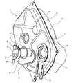
図2は、本発明の一実施形態に係る部材接合方法を適用した燃料タンク1の概要説明図である。燃料タンク1は、鋼板からプレス成形された上側部材2および下側部材3を、それぞれの周縁部4において溶接接合することで一体的な容器として形成したものである。前記上側部材2の上面部には、給油口5と、燃料ポンプユニット10を取付けるための開口部6とが設けられている。給油の度に開閉される前記給油口5の上部には、燃料タンク1を車両に搭載する際に、着脱自在または開閉可能な蓋が設けられる。一方、前記開口部6は、燃料タンク1の組み立て時に燃料ポンプユニット10が一度取り付けられると、該燃料ポンプユニット10の分解整備等が行われる時以外に開口されることはない。
FIG. 2 is a schematic explanatory view of the
前記燃料ポンプユニット10は、燃料の吐出ノズル14および駆動モータの駆動信号を受け取るコネクタ15が設けられた蓋部13の下部に、燃料タンク1内の燃料を圧送する前記駆動モータが内蔵された略円筒形状の本体部11と、燃料に混入した不純物等を濾過するフィルタを内蔵したストレーナ12とが連結された構成とされている。
The
前記開口部6には、燃料ポンプユニット10を取付けるためのベース部材としてのベース7およびガイド部材としてのプレート8が接合されている。前記ベース7は、被溶接材に突起(プロジェクション)を設け、その上下に配置した溶接用の電極によって通電加圧することで、前記突起部に熱および圧力を集中させて溶融あるいは塑性流動を生じさせるプロジェクション溶接によって前記上側部材2に接合されている。なお、前記プレート8は、ベース7の上面に4箇所のスポット溶接によって接合されている。
A
前記ベース7の内壁面と前記蓋部13との間には、弾性を有した樹脂等で形成される略円形断面の密閉用シールであるOリング16が配置される。前記燃料ポンプユニット10は、前記開口部6からその全体を挿入した後に、保持器としてのリテーナ20を装着することで、燃料タンク1に密閉固定される。
Between the inner wall surface of the
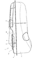
図3は、前記燃料タンク1の側面図である。前記と同一の符号は、前記と同一または同等部分を示す。前記上側部材2を形成する鋼板2aは、前記開口部6の周縁部において下側部材3の方向へ略直角に折り曲げられている。前記鋼板2aとベース7の間のプロジェクション溶接は、前記ベース7の周縁部7aの全周に渡るリングプロジェクション溶接として施されており、本発明の一実施形態に係る部材接合方法は、このリングプロジェクション溶接部に適用されている。なお、前記プレート8には、ベース7との間に前記リテーナ20が挿入可能な間隙を設けるための段差が形成されている。
FIG. 3 is a side view of the
図4は、本発明の一実施形態に係る燃料ポンプユニットの取付部の概要説明図である。前記と同一の符号は、前記と同一または同等部分を示す。前記リテーナ20が挿入される方向から見た該図を参照して、前記燃料ポンプユニット10の取付手順を説明する。まず、前記Oリング16を、ベース7の内周部に形成された段部50に収まるように配置する。次に、燃料ポンプユニット10を傾けながらストレーナ12の先端から開口部6に挿入する。そして、本体部11がすべて開口部6に収まると、前記蓋部13の外周部とベース7の段部との間で、前記Oリング16がシール作用を発揮するように構成されている。この状態において、前記リテーナ20をベース7とプレート8との間の間隙18に挿入すると、該リテーナ20の先端部は、前記蓋部13の上面側を通って、挿入方向と反対側の間隙18に進入することになる。上記したような構成によって、燃料ポンプユニット10は、前記リテーナ20を取り外さない限り燃料タンク1に固定された状態を保持することになる。なお、本実施形態では、前記プレート8をベース7に接合するためのスポット溶接は、4箇所のスポット溶接部17において行われているが、これに限定されるものではない。
FIG. 4 is a schematic explanatory view of a mounting portion of the fuel pump unit according to one embodiment of the present invention. The same reference numerals as those described above denote the same or equivalent parts as described above. With reference to the figure seen from the direction in which the
図5は、前記燃料ポンプユニット10の断面図である。前記と同一の符号は、前記と同一または同等部分を示す。該燃料ポンプユニット10は、円筒状のハウジングである本体部11の内部に駆動モータ30を内蔵しており、その回転軸31には、羽根車としてのインペラ32が取り付けられている。前記コネクタ15がECU(不図示)からの駆動信号を受け取り、前記駆動モータ30が回転すると、前記インペラ32が回転することによって前記ストレーナ12から燃料が吸い出される。前記インペラ32の回転力によって吸い出された燃料は、前記駆動モータ30内部の潤滑を行いながら燃料ポンプユニット10の上方に圧送され、吐出口14から前記エンジン87に燃料を供給する燃料噴射装置に向けて吐出されることになる。本実施形態では、前記プレート7と密閉固定するためのシール部材に略円形断面のOリング16を使用するので、該Oリング16と当接する段部40を、平面部材による円環状の面シールを使用する従来方式に比して大幅に小型化することを可能としている。これに合わせて、燃料ポンプユニット10の構成も、蓋部13の上面に吐出ノズル14およびコネクタ15を設けた「上出し仕様」とすることで、前記蓋部13の直径を可能な限り低減させている。
FIG. 5 is a cross-sectional view of the
図6(a),(b)は、それぞれ前記蓋部13の上面図および側面図である。前記と同一の符号は、前記と同一または同等部分を示す。本実施形態では、挿入したリテーナ20が一度所定の位置で固定されると、意図的に所定の動作を実行しない限り抜けない(ロックされる)ように構成されている。該ロック機能は、主に蓋部13およびリテーナ20の形状によって発揮される。該図の蓋部13においては、前記リテーナ20を挿入した際に、略U字型のリテーナ20の任意の部分に当接する3箇所に、凸部としてのスロープ13a,13bが設けられている。該スロープ13a,13bは、前記リテーナ20が挿入される方向から傾斜がなだらかに立ち上がる形状とされている。
6 (a) and 6 (b) are a top view and a side view of the
図7(a),(b)は、それぞれ前記リテーナ20の上面図および側面図である。前記と同一の符号は、前記と同一または同等部分を示す。該リテーナ20は、外部から応力が加えられると弾性変形し、前記応力から開放されると元の形状に戻る薄い鋼板等で形成されている。取っ手としての折り曲げ部25を除いて平板状とされるリテーナ20は、係合部材としてのメインプレート21と、連結部22によって前記メインプレート21の内側に連結される押圧部材としてのサブプレート23,24とによって構成されている。また、前記サブプレート23の係止部としての先端部23aは、メインプレート21の先端部21aよりその突出長が短くされている。また、略U字形状の前記サブプレート24の中央部には、前記リテーナの挿入方向側に突起部24cが設けられると共に、2つの屈曲部24aのそれぞれの外周側において略直線状の係止部24bが形成されている。
7A and 7B are a top view and a side view of the
図8は、前記燃料ポンプユニット10を燃料タンク1に取付けた状態における上面図である。前記と同一の符号は、前記と同一または同等部分を示す。以下、この図8および図8のA−A線断面図である図9を参照して、前記リテーナ20のロック機能について詳細に説明する。
FIG. 8 is a top view of the
まず、前記燃料ポンプユニット10を開口部6(図4参照)に挿入し、前記ベース7の段部50に蓋部13の底面が当接するまで押し込むと、Oリング16が変形して所定のシール作用を発揮するようになる。ここで、前記リテーナ20を、図示左方向からベース7とプレート8との間に形成されている間隙18(図4参照)に挿入すると、リテーナ20のメインプレート21の先端部21aは、前記蓋部13の上面を通ってガイド部材であるプレート8に係合し、図示右側の間隙18にまで届く。この時、前記サブプレート23の先端部23aは、前記スロープ13bに沿ってせり上げられていき、サブプレート23を弾性変形させる。これによって、前記サブプレート23が蓋部13を押圧すると共に、その先端部23aがプレート8の内周の側面部に当接またはほぼ当接した状態となる。
First, when the
一方、前記サブプレート24の突起部24cは、前記蓋部13のスロープ13aに沿ってせり上げられることでサブプレート24を弾性変性させる。これによって、前記サブプレート24が蓋部13を押圧すると共に、その係止部24bがプレート8の内周の側面部に当接またはほぼ当接した状態となる。上記した動作から、前記リテーナ20には、スロープ13a,13bによってせり上げられたサブプレート23,24によって、挿入する方向にも引き抜く方向にも移動できないロック機能が発揮されることになる。なお、前記燃料ポンプユニット10を燃料タンク1から取り外す時は、前記サブプレート24の係止部24aの近傍を下方に押圧するという所定の動作を実行することによって、前記サブプレート24を弾性変形させて前記係止部24aの係止状態を解除しながら、前記リテーナ20を挿入した方向から引き抜けばよい。
On the other hand, the
上記したような燃料ポンプ取付構造によれば、シール部材に略円形断面のOリングを使用すると共に、取付ボルトを不要とする構造としたので、燃料ポンプユニットの取付に係る部品の小径化が可能となり、取付に要するスペースを大幅に低減できるようになる。また、取付ボルトを不要とし、リテーナを挿入するのみで燃料ポンプユニットを密閉固定できるので、組み立て時の作業工程を低減することができるようになる。さらに、前記蓋部およびリテーナの形状によって、所定の動作を実行しなければリテーナが取り外せないロック機能を有するように構成したので、燃料ポンプユニットの着脱を確実かつ容易に行うことができるようになる。 According to the fuel pump mounting structure as described above, the O-ring having a substantially circular cross section is used for the seal member and the mounting bolt is not required, so the diameter of the parts related to the mounting of the fuel pump unit can be reduced. Thus, the space required for mounting can be greatly reduced. In addition, the mounting bolt is not required and the fuel pump unit can be hermetically fixed simply by inserting the retainer, so that the work process during assembly can be reduced. Further, the configuration of the lid and the retainer is configured to have a lock function that the retainer cannot be removed unless a predetermined operation is performed, so that the fuel pump unit can be attached and detached reliably and easily. .
図10(a),(b)は、それぞれ前記ベース7の上面図と、そのB−B線断面図である。前記と同一の符号は、前記と同一または同等部分を示す。前記ベース7は、鋼板を円環状に打ち抜いた部材に、プレス加工を施すことによって製作されている。本発明に係る部材接合方法においては、このプレス加工時に、前記Oリング16および蓋部13を収めるための段部50が形成されるように母材33に屈曲部34,35が設けられると共に、周縁部7aの近傍に湾曲部36が設けられている点に特徴がある。
10A and 10B are a top view of the
図11は、本実施形態に係るプロジェクション溶接工程の手順を示すフローチャートである。まず、ステップS10の突起形成工程にてプロジェクションの形成が行われる。該突起形成工程には、前記したように、前記ベース7の製作と同時にベース7の周縁部にプロジェクションが形成されることに相当し、図12のサブフローチャートに示されるように、ステップS20の部材打ち抜き工程と、ステップS21のプレス工程とが含まれる。ステップS11以降は後述する。
FIG. 11 is a flowchart showing the procedure of the projection welding process according to the present embodiment. First, a projection is formed in the protrusion forming step in step S10. As described above, the projection forming step corresponds to the formation of the projection on the peripheral edge of the
図13は、図10(b)の一部拡大図である。前記と同一の符号は、前記と同一または同等部分を示す。前記したように、本実施形態におけるベース7は、平滑な鋼板から円環状の部材を打ち抜いて形成されている(前記ステップS20)ので、その周縁部7aの端面(切断面)は、母材33の平面部に対して略90度の角度をなしている。このため、前記プレス加工(前記ステップS21)によって、前記ベース7の周縁部7aおよびその近傍が湾曲部36によって略円弧状または所定の角度に曲げられることで形成される突起部36aは、略90度の鋭利な頂部を有することになる。本発明に係る部材接合方法においては、この突起部36aをプロジェクション溶接用のプロジェクションとして使用するので、切削加工等によって製造工程を増加させることなく、鋭利な形状のプロジェクションを得ることができるようになる。
FIG. 13 is a partially enlarged view of FIG. The same reference numerals as those described above denote the same or equivalent parts as described above. As described above, since the
図14は、前記ベース7と鋼板2aとのプロジェクション溶接の状態を示す説明図である。プロジェクション溶接は、前記鋼板2aとベース7とを、プロジェクション溶接用の上側電極45および下側電極46とに挟まれた所定の箇所に配置し、前記上側電極45と下側電極46との間で通電加圧することによって実行される。上記した工程の流れは、図11のフローチャートに示されるように、ステップS11において部材重ね合わせ工程が実行され、続くステップS12において電極狭持工程が実行され、そして、ステップS13において通電加圧工程が実行されることに相当する。この時、前記突起部36aがプロジェクションとして作用し、ベース7と鋼板2aとの接合が良好に行われることになる。また、本実施形態に係る部材接合方法では、突起部36aの頂部が鋭利で、鋼板2aとの接触面積が小さいため、上側電極45および下側電極46の間に生じる大きな電気抵抗によって、電流および発熱を集中させることができる。上記したように、本発明に係る部材接合方法によれば、製造工程を増大することなく、所定のプロジェクションを容易に形成することができるようになる。また、切削加工等を行うことなく、大径のリングプロジェクション溶接等に適した、頂部が鋭利な形状のプロジェクションを得ることができるようになる。さらに、プレスの金型の変更等によって、任意の形状のプロジェクションが容易に得られるようになる。
FIG. 14 is an explanatory view showing a state of projection welding between the
図15は、本発明の第2実施形態に係る部材接合方法を適用したベースの一部拡大断面図である。本実施形態においては、前記ベース7の外周部にプレス加工によって湾曲部36を形成した後に、その周方向外側の部材60をカットすることで、周縁部7bおよび突起部36bを形成する点に特徴がある。本実施形態に係る部材接合方法によれば、この突起部36bをプロジェクション溶接用のプロジェクションとして使用するので、前記カットの方向によって先端の角度を任意に形成することができ、大径のリングプロジェクション溶接等に適したプロジェクションを容易に得ることができるようになる。
FIG. 15 is a partially enlarged cross-sectional view of a base to which the member joining method according to the second embodiment of the present invention is applied. In the present embodiment, after the
なお、ベースやプロジェクションの形状などは、上記した実施形態に限定されずに種々の変形が可能である。また、本発明に係る部材接合方法および部材接合構造体が、燃料タンク以外の構造物にも適用可能であることは勿論である。 The shape of the base and the projection is not limited to the above-described embodiment, and various modifications can be made. Of course, the member joining method and the member joining structure according to the present invention can be applied to structures other than the fuel tank.
2a…鋼板、7…ベース、7a…周縁部、33…母材、34,35…屈曲部、36…湾曲部、36a…突起部、45…上側電極、46…下側電極、50…段部 2a ... Steel plate, 7 ... Base, 7a ... Peripheral part, 33 ... Base material, 34, 35 ... Bent part, 36 ... Curved part, 36a ... Projection part, 45 ... Upper electrode, 46 ... Lower electrode, 50 ... Step part
Claims (3)
一方側の部材の板状部の端部を溶接面側に湾曲させて突起を形成する工程と、
前記端部を他方の部材の板状部に重ね合わせる工程と、
前記2つの部材を溶接用の電極で狭持する工程と、
前記2つの部材を前記電極で通電加圧することによってプロジェクション溶接を行う工程とを含むことを特徴とする部材接合方法。 In a member joining method for joining two members having a plate-like portion by projection welding,
A step of bending the end of the plate-like portion of the member on one side to the welding surface side to form a projection;
Superimposing the end on the plate-like part of the other member;
Sandwiching the two members with welding electrodes;
And a step of performing projection welding by energizing and pressing the two members with the electrodes.
一方側の部材の板状部の端部を溶接面側に湾曲させて形成された突起と、
前記突起を他方側の部材の板状部に当接し、通電加圧によって形成されたプロジェクション溶接部とを具備したことを特徴とする部材接合構造体。 In a member joint structure for joining two members having a plate-like portion by projection welding,
A protrusion formed by curving the end of the plate-like portion of the member on one side toward the welding surface;
A member bonded structure comprising: a projection welded portion formed by energizing and pressing, wherein the projection is brought into contact with the plate-like portion of the other member.
プレス加工によって周縁部の端部を溶接面側に湾曲させて突起を形成した略円環状のベース部材を具備し、
前記端部をプロジェクションとして、前記燃料タンクの壁面に前記ベース部材をリングプロジェクション溶接によって接合し、
前記ベース部材に前記燃料ポンプユニットの端部を嵌合固定することを特徴とする燃料タンク。 In the fuel tank adapted to receive the fuel pump unit from the opening of the fuel tank,
A substantially annular base member having a protrusion formed by curving the edge of the peripheral edge toward the weld surface by pressing;
The end part as a projection, the base member is joined to the wall surface of the fuel tank by ring projection welding,
An end portion of the fuel pump unit is fitted and fixed to the base member.
Priority Applications (1)
| Application Number | Priority Date | Filing Date | Title |
|---|---|---|---|
| JP2005318831A JP2007125571A (en) | 2005-11-01 | 2005-11-01 | Method for joining members, structure of joined members, and fuel tank |
Applications Claiming Priority (1)
| Application Number | Priority Date | Filing Date | Title |
|---|---|---|---|
| JP2005318831A JP2007125571A (en) | 2005-11-01 | 2005-11-01 | Method for joining members, structure of joined members, and fuel tank |
Publications (1)
| Publication Number | Publication Date |
|---|---|
| JP2007125571A true JP2007125571A (en) | 2007-05-24 |
Family
ID=38148670
Family Applications (1)
| Application Number | Title | Priority Date | Filing Date |
|---|---|---|---|
| JP2005318831A Pending JP2007125571A (en) | 2005-11-01 | 2005-11-01 | Method for joining members, structure of joined members, and fuel tank |
Country Status (1)
| Country | Link |
|---|---|
| JP (1) | JP2007125571A (en) |
Cited By (1)
| Publication number | Priority date | Publication date | Assignee | Title |
|---|---|---|---|---|
| CN101396761B (en) * | 2007-09-24 | 2013-05-29 | 通用汽车环球科技运作公司 | System for and method of edge welding using projections |
Citations (3)
| Publication number | Priority date | Publication date | Assignee | Title |
|---|---|---|---|---|
| JPH0618045U (en) * | 1992-08-07 | 1994-03-08 | 堀江金属工業株式会社 | Fuel tank |
| JPH106024A (en) * | 1996-06-21 | 1998-01-13 | Toyota Motor Corp | Projection forming and projection welding method |
| JP2002239738A (en) * | 2001-02-08 | 2002-08-28 | Toyota Motor Corp | Method for joining two members |
-
2005
- 2005-11-01 JP JP2005318831A patent/JP2007125571A/en active Pending
Patent Citations (3)
| Publication number | Priority date | Publication date | Assignee | Title |
|---|---|---|---|---|
| JPH0618045U (en) * | 1992-08-07 | 1994-03-08 | 堀江金属工業株式会社 | Fuel tank |
| JPH106024A (en) * | 1996-06-21 | 1998-01-13 | Toyota Motor Corp | Projection forming and projection welding method |
| JP2002239738A (en) * | 2001-02-08 | 2002-08-28 | Toyota Motor Corp | Method for joining two members |
Cited By (1)
| Publication number | Priority date | Publication date | Assignee | Title |
|---|---|---|---|---|
| CN101396761B (en) * | 2007-09-24 | 2013-05-29 | 通用汽车环球科技运作公司 | System for and method of edge welding using projections |
Similar Documents
| Publication | Publication Date | Title |
|---|---|---|
| JP4488362B2 (en) | Fuel pump mounting structure | |
| JP5322074B2 (en) | Welded joint between a thick component and a thin component and a fuel high-pressure pump used in an internal combustion engine | |
| JP5864456B2 (en) | Dissimilar material joint structure | |
| US6572196B1 (en) | Structural part connection between two structural parts of a car seat | |
| JP2007125571A (en) | Method for joining members, structure of joined members, and fuel tank | |
| JP5172502B2 (en) | Body frame connection structure and molding method | |
| JP5227388B2 (en) | Dissimilar material joint structure | |
| EP0622150B1 (en) | Laser welding method of stamped workpieces flanges | |
| JP3838335B2 (en) | Two-member joining method | |
| JP2019064322A (en) | Resin tank | |
| JP5351489B2 (en) | toilet seat | |
| JP5659141B2 (en) | Vehicle operation pedal | |
| EP2383174A2 (en) | Saddle-Riding Vehicle | |
| CN101131190B (en) | Cylinder device and method for manufacturing the same | |
| JP2003320462A (en) | Method for projection welding and projection for resistance welding | |
| JP2006000878A (en) | Spot welding apparatus | |
| JP2019064323A (en) | Resin fuel tank | |
| JP6704885B2 (en) | Resin fuel tank | |
| JPH11254979A (en) | Fuel filler neck bracket fixing device for automobile | |
| JP3861111B2 (en) | Assembly structure of sheet metal parts | |
| JP2020059374A (en) | Fuel tank | |
| JP2016175589A (en) | Fuel tank of saddle-riding type vehicle | |
| JP3393348B2 (en) | Automotive Door Panel Welding Method | |
| JP6190303B2 (en) | Body frame for saddle-ride type vehicles | |
| JP3838949B2 (en) | Steering column support device |
Legal Events
| Date | Code | Title | Description |
|---|---|---|---|
| A621 | Written request for application examination |
Effective date: 20071127 Free format text: JAPANESE INTERMEDIATE CODE: A621 |
|
| A977 | Report on retrieval |
Effective date: 20091120 Free format text: JAPANESE INTERMEDIATE CODE: A971007 |
|
| A131 | Notification of reasons for refusal |
Free format text: JAPANESE INTERMEDIATE CODE: A131 Effective date: 20091202 |
|
| A02 | Decision of refusal |
Effective date: 20100331 Free format text: JAPANESE INTERMEDIATE CODE: A02 |