JP2007122960A - Fuel cell - Google Patents
Fuel cell Download PDFInfo
- Publication number
- JP2007122960A JP2007122960A JP2005311251A JP2005311251A JP2007122960A JP 2007122960 A JP2007122960 A JP 2007122960A JP 2005311251 A JP2005311251 A JP 2005311251A JP 2005311251 A JP2005311251 A JP 2005311251A JP 2007122960 A JP2007122960 A JP 2007122960A
- Authority
- JP
- Japan
- Prior art keywords
- fuel
- liquid
- electrode
- gas
- liquid fuel
- Prior art date
- Legal status (The legal status is an assumption and is not a legal conclusion. Google has not performed a legal analysis and makes no representation as to the accuracy of the status listed.)
- Pending
Links
Images


Classifications
-
- H—ELECTRICITY
- H01—ELECTRIC ELEMENTS
- H01M—PROCESSES OR MEANS, e.g. BATTERIES, FOR THE DIRECT CONVERSION OF CHEMICAL ENERGY INTO ELECTRICAL ENERGY
- H01M8/00—Fuel cells; Manufacture thereof
- H01M8/10—Fuel cells with solid electrolytes
- H01M8/1009—Fuel cells with solid electrolytes with one of the reactants being liquid, solid or liquid-charged
-
- H—ELECTRICITY
- H01—ELECTRIC ELEMENTS
- H01M—PROCESSES OR MEANS, e.g. BATTERIES, FOR THE DIRECT CONVERSION OF CHEMICAL ENERGY INTO ELECTRICAL ENERGY
- H01M8/00—Fuel cells; Manufacture thereof
- H01M8/04—Auxiliary arrangements, e.g. for control of pressure or for circulation of fluids
- H01M8/04082—Arrangements for control of reactant parameters, e.g. pressure or concentration
- H01M8/04186—Arrangements for control of reactant parameters, e.g. pressure or concentration of liquid-charged or electrolyte-charged reactants
-
- H—ELECTRICITY
- H01—ELECTRIC ELEMENTS
- H01M—PROCESSES OR MEANS, e.g. BATTERIES, FOR THE DIRECT CONVERSION OF CHEMICAL ENERGY INTO ELECTRICAL ENERGY
- H01M8/00—Fuel cells; Manufacture thereof
- H01M8/04—Auxiliary arrangements, e.g. for control of pressure or for circulation of fluids
- H01M8/04082—Arrangements for control of reactant parameters, e.g. pressure or concentration
- H01M8/04201—Reactant storage and supply, e.g. means for feeding, pipes
- H01M8/04208—Cartridges, cryogenic media or cryogenic reservoirs
-
- H—ELECTRICITY
- H01—ELECTRIC ELEMENTS
- H01M—PROCESSES OR MEANS, e.g. BATTERIES, FOR THE DIRECT CONVERSION OF CHEMICAL ENERGY INTO ELECTRICAL ENERGY
- H01M8/00—Fuel cells; Manufacture thereof
- H01M8/04—Auxiliary arrangements, e.g. for control of pressure or for circulation of fluids
- H01M8/04082—Arrangements for control of reactant parameters, e.g. pressure or concentration
- H01M8/04089—Arrangements for control of reactant parameters, e.g. pressure or concentration of gaseous reactants
- H01M8/04119—Arrangements for control of reactant parameters, e.g. pressure or concentration of gaseous reactants with simultaneous supply or evacuation of electrolyte; Humidifying or dehumidifying
- H01M8/04156—Arrangements for control of reactant parameters, e.g. pressure or concentration of gaseous reactants with simultaneous supply or evacuation of electrolyte; Humidifying or dehumidifying with product water removal
- H01M8/04164—Arrangements for control of reactant parameters, e.g. pressure or concentration of gaseous reactants with simultaneous supply or evacuation of electrolyte; Humidifying or dehumidifying with product water removal by condensers, gas-liquid separators or filters
-
- Y—GENERAL TAGGING OF NEW TECHNOLOGICAL DEVELOPMENTS; GENERAL TAGGING OF CROSS-SECTIONAL TECHNOLOGIES SPANNING OVER SEVERAL SECTIONS OF THE IPC; TECHNICAL SUBJECTS COVERED BY FORMER USPC CROSS-REFERENCE ART COLLECTIONS [XRACs] AND DIGESTS
- Y02—TECHNOLOGIES OR APPLICATIONS FOR MITIGATION OR ADAPTATION AGAINST CLIMATE CHANGE
- Y02E—REDUCTION OF GREENHOUSE GAS [GHG] EMISSIONS, RELATED TO ENERGY GENERATION, TRANSMISSION OR DISTRIBUTION
- Y02E60/00—Enabling technologies; Technologies with a potential or indirect contribution to GHG emissions mitigation
- Y02E60/30—Hydrogen technology
- Y02E60/50—Fuel cells
Abstract
Description
本発明は、燃料電池、特に小型のパッシブ型の燃料電池に関する。 The present invention relates to a fuel cell, and more particularly to a small passive fuel cell.
近年の半導体技術の発達に伴い、OA機器、オーディオ機器などの電子機器の小型化、高性能化、ポータブル化が進み、これら携帯用電子機器に使用される電池の高エネルギ密度化の要求が強まっている。 With the recent development of semiconductor technology, electronic devices such as OA equipment and audio equipment have been reduced in size, performance, and portability, and the demand for higher energy density of batteries used in these portable electronic equipment has increased. ing.
このような状況のもと、小型の燃料電池が注目を集めている。特に、メタノールを燃料として用いた直接メタノール型燃料電池(DMFC:Direct Methanol Fuel Cell)は、水素ガスを使用する燃料電池に比べ、水素ガスの取り扱いの困難さを回避でき、また有機燃料を改質して水素を作り出す装置等が必要なく、小型化に優れていると考えられる。 Under such circumstances, small fuel cells are attracting attention. In particular, direct methanol fuel cells (DMFC) using methanol as fuel can avoid the difficulty of handling hydrogen gas compared to fuel cells using hydrogen gas, and reform organic fuel. Therefore, it is considered that the device for producing hydrogen is not necessary and is excellent in miniaturization.
DMFCでは、燃料極(アノード)においてメタノールが酸化分解され、二酸化炭素、プロトンおよび電子が生成される。一方、空気極(カソード)では、空気から得られる酸素と、電解質膜を経て燃料極から供給されるプロトン、および燃料極から外部回路を通じて供給される電子によって水が生成される。また、この外部回路を通る電子によって、電力が供給されることになる。 In DMFC, methanol is oxidatively decomposed at the fuel electrode (anode) to generate carbon dioxide, protons and electrons. On the other hand, in the air electrode (cathode), water is generated by oxygen obtained from air, protons supplied from the fuel electrode through the electrolyte membrane, and electrons supplied from the fuel electrode through an external circuit. In addition, power is supplied by electrons passing through the external circuit.
DMFCにおける燃料供給の方法としては、燃料タンクに収容された液体燃料を、直接、液体燃料含浸部の主面に接触させて、液体燃料含浸部に含浸させ、燃料極側に液体燃料を供給する技術が開示されている(例えば、特許文献1−4参照。)。
燃料電池では、カソード触媒層において、水を生成する発電反応を生じ、この反応が進行してカソード触媒層における水分貯蔵量が多くなると、浸透圧現象によって、電解質膜を介して生成した水のアノード触媒層側への移動が促進される。 In a fuel cell, a power generation reaction that generates water occurs in the cathode catalyst layer, and when this reaction proceeds and the amount of water stored in the cathode catalyst layer increases, the anode of the water generated through the electrolyte membrane by the osmotic pressure phenomenon. The movement to the catalyst layer side is promoted.
上記した従来の燃料電池では、アノード触媒層側へ移動した水が水蒸気となり、液体燃料含浸部を介して燃料タンク内に拡散し、それらの部位で水蒸気が冷却されることで凝縮して水となることがあった。これにより、それらの部位における燃料濃度が低下し、所定の電池出力が得られないという問題を生じることがあった。 In the above-described conventional fuel cell, the water moved to the anode catalyst layer side becomes water vapor, diffuses into the fuel tank through the liquid fuel impregnation portion, and is condensed by cooling the water vapor at those portions. There was. As a result, there is a problem that the fuel concentration at those portions is lowered and a predetermined battery output cannot be obtained.
また、上記のように液体燃料を燃料極側に直接供給する方法以外に、液体燃料が気化した気化燃料を燃料極側に供給する方法も考えられる。しかし、この方式では、液体燃料の気化速度によって気化燃料の供給速度が制限されるため、大電量で発電しようとした場合に気化燃料の供給が追いつかず、このために燃料電池の電圧が低下してしまい、一定以上の発電出力を得ることが困難であるという問題があった。 In addition to the method of supplying liquid fuel directly to the fuel electrode side as described above, a method of supplying vaporized fuel vaporized from the liquid fuel to the fuel electrode side is also conceivable. However, in this method, since the vaporized fuel supply rate is limited by the vaporization rate of the liquid fuel, the supply of vaporized fuel cannot catch up when trying to generate electricity with a large amount of electricity, which reduces the voltage of the fuel cell. Therefore, there is a problem that it is difficult to obtain a power generation output above a certain level.
そこで、本発明は、上記課題を解決するためになされたものであり、燃料タンク内などにおける液体燃料の濃度を一定に維持し、液体燃料の気化を促進して、安定した電池出力を得ることができる燃料電池を提供することを目的とする。 Accordingly, the present invention has been made to solve the above-described problem, and maintains a constant concentration of liquid fuel in a fuel tank or the like, promotes vaporization of the liquid fuel, and obtains stable battery output. An object of the present invention is to provide a fuel cell capable of performing
上記目的を達成するために、本発明の燃料電池は、燃料極、空気極、および前記燃料極と前記空気極とに挟持された電解質膜から構成される膜電極接合体と、液体燃料を収容する燃料タンクと、前記燃料タンクと前記膜電極接合体の燃料極側との間に配設され、前記燃料極から拡散した水蒸気と前記液体燃料との間の熱交換を行い、前記液体燃料の気化成分を前記燃料極側に通過させる気液分離層とを具備することを特徴とする。 In order to achieve the above object, a fuel cell of the present invention contains a fuel electrode, an air electrode, a membrane electrode assembly composed of an electrolyte membrane sandwiched between the fuel electrode and the air electrode, and a liquid fuel. A fuel tank that is disposed between the fuel tank and the fuel electrode side of the membrane electrode assembly, and performs heat exchange between the water vapor diffused from the fuel electrode and the liquid fuel, And a gas-liquid separation layer that allows the vaporized component to pass to the fuel electrode side.
この燃料電池によれば、気液分離膜を介して、燃料極から拡散した水蒸気と液体燃料との間で熱交換を行うことができるので、液体燃料の気化を促進することができる。また、燃料極から拡散した水蒸気は、気液分離膜の燃料極側の面で凝縮して水となるので、水蒸気が気液分離膜を通過して液体燃料タンク内に拡散することを防止できる。 According to this fuel cell, since the heat exchange can be performed between the water vapor diffused from the fuel electrode and the liquid fuel through the gas-liquid separation membrane, the vaporization of the liquid fuel can be promoted. Further, since the water vapor diffused from the fuel electrode is condensed on the fuel electrode side surface of the gas-liquid separation membrane to become water, it is possible to prevent the water vapor from passing through the gas-liquid separation membrane and diffusing into the liquid fuel tank. .
本発明の燃料電池によれば、燃料タンク内などにおける液体燃料の濃度を一定に維持し、液体燃料の気化を促進して、安定した電池出力を得ることができる。 According to the fuel cell of the present invention, the concentration of the liquid fuel in the fuel tank or the like can be kept constant, the vaporization of the liquid fuel can be promoted, and a stable battery output can be obtained.
以下、本発明の一実施の形態について図を参照して説明する。 Hereinafter, an embodiment of the present invention will be described with reference to the drawings.
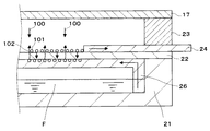
図1には、本発明に係る一実施の形態の直接メタノール型の燃料電池10の断面図が模式的に示されている。
FIG. 1 schematically shows a cross-sectional view of a direct
図1に示すように、燃料電池10は、アノード触媒層11およびアノードガス拡散層12からなる燃料極と、カソード触媒層13およびカソードガス拡散層14からなる空気極と、アノード触媒層11とカソード触媒層13との間に挟持されたプロトン(水素イオン)伝導性の電解質膜15とから構成される膜電極接合体(MEA:Membrane Electrode Assembly )16を起電部として構成している。
As shown in FIG. 1, the
アノード触媒層11およびカソード触媒層13に含有される触媒としては、例えば、白金族元素である、Pt、Ru、Rh、Ir、Os、Pdなどの単体金属、白金族元素を含有する合金などを挙げることができる。具体的には、アノード触媒層11として、メタノールや一酸化炭素に対して強い耐性を有するPt−RuやPt−Moなど、カソード触媒層13として、白金やPt−Niなどを用いることが好ましいが、これらに限られるものではない。また、炭素材料のような導電性担持体を使用する担持触媒、あるいは無担持触媒を使用してもよい。
Examples of the catalyst contained in the
電解質膜15を構成するプロトン伝導性材料としては、例えば、スルホン酸基を有する、例えば、パーフルオロスルホン酸重合体などのフッ素系樹脂(ナフィオン(商品名、デュポン社製)、フレミオン(商品名、旭硝子社製)など)、スルホン酸基を有する炭化水素系樹脂、タングステン酸やリンタングステン酸などの無機物等が挙げられるが、これらに限定されるものではない。
Examples of the proton conductive material constituting the
アノード触媒層11に積層されたアノードガス拡散層12は、アノード触媒層11に燃料を均一に供給する役割を果たすと同時に、アノード触媒層11の集電体としての機能も兼ね備えている。一方、カソード触媒層13に積層されたカソードガス拡散層14は、カソード触媒層13に空気等の酸化剤を均一に供給する役割を果たすと同時に、カソード触媒層13の集電体としての機能も兼ね備えている。そして、アノードガス拡散層12の表面には、アノード導電層17が配設され、カソードガス拡散層14の表面には、カソード導電層18が配設されている。アノード導電層17およびカソード導電層18は、例えば、金などの導電金属材料からなるメッシュなどの多孔質層や、開孔を有する板あるいは箔などで構成される。なお、アノード導電層17およびカソード導電層18は、それらの周縁から燃料や酸化剤が漏れないように構成される。
The anode
アノードシール材19は、矩形枠状を有し、アノード導電層17と電解質膜15との間に位置するとともに、アノード触媒層11およびアノードガス拡散層12の周囲を囲んでいる。一方、カソードシール材20は、矩形枠状を有し、カソード導電層18と電解質膜15との間に位置するとともに、カソード触媒層13およびカソードガス拡散層14の周囲を囲んでいる。アノードシール材19およびカソードシール材20は、例えば、ゴム製のOリングなどで構成され、膜電極接合体16からの燃料漏れおよび酸化剤漏れを防止している。なお、アノードシール材19およびカソードシール材20の形状は、矩形枠状に限られず、燃料電池10の外縁形に対応するように適宜に構成される。
The
また、液体燃料Fを収容する液体燃料タンク21の開口部を覆うように配設された気液分離膜22上には、燃料電池10の外縁形に対応した形状で構成されたフレーム23(ここでは矩形のフレーム)が配置される。そして、このフレーム23の一方の面に、アノード導電層17が接するように、上記したアノード導電層17およびカソード導電層18を備えた膜電極接合体16が積層配置されている。また、フレーム23、気液分離膜22およびアノード導電層17で囲まれた気化燃料収容室25は、気液分離膜22を透過してきた液体燃料Fの気化成分を一時的に収容し、さらに気化成分における燃料の濃度分布を均一にする空間として機能する。ここで、フレーム23は、電気絶縁材料で構成され、具体的には、例えばポリエチレンテレフタレート(PET)のような熱可塑性ポリエステル樹脂などで形成される。
On the gas-
また、気化燃料収容室25内に、気液分離膜22の一部に面して、水排出手段24が設けられ、水排出手段24の一部は、燃料電池10の外部に突出されている。この水排出手段24は、気液分離膜22上の水を燃料電池10の外部に導くものである。水排出手段24を構成する材料は、気孔率が10〜90%で、吸水率が30〜90%である材料を用いることが好ましい。
A water discharge means 24 is provided in the vaporized
ここで、この範囲の気孔率が好ましいのは、気孔率が10%より小さい場合には、十分な排水量や排水速度を確保することが困難であり、90%より大きい場合には、気孔径が大きくなって毛管力が低下するためにかえって水排出手段の中に水を保持しにくくなることや、水排出手段自身の強度が低下してしまい長時間使用していると変形などを生じ、そのために排水速度が低下するなどの不具合を生じるからである。 Here, the porosity in this range is preferable when the porosity is less than 10%, it is difficult to ensure a sufficient amount of drainage and drainage speed, and when the porosity is greater than 90%, the pore diameter is Since it becomes larger and the capillary force decreases, it becomes difficult to hold water in the water discharge means, and the strength of the water discharge means itself decreases, causing deformation etc. if used for a long time. This is because problems such as a decrease in the drainage rate occur.
また、上記した範囲の吸水率が好ましいのは、吸水率が30%より小さい場合には、気孔率が小さい場合と同様に十分な排水量や排水速度を確保することが困難であり、90%より大きい場合には、吸収した燃料で燃料供給手段自体が膨張、膨潤などを生じることにより、形状を維持することが困難となるからである。具体的には、水排出手段24は、ポリエステル、ナイロン、アクリルなどの合成繊維や、ガラスなどの無機物繊維、綿、毛、絹、紙などの天然繊維などで形成された不織布や織布、あるいは発砲ポリウレタン、発砲ポリスチレン、多孔性ポリエチレンなどの合成樹脂多孔質体、海綿などの天然多孔質体などで構成される。なお、水排出手段24が水を含浸している場合には、水排出手段24を介して外部に燃料などが漏れることはない。 Further, the water absorption rate in the above-described range is preferable because when the water absorption rate is smaller than 30%, it is difficult to ensure a sufficient amount of drainage and drainage rate as in the case where the porosity is small. This is because when the size is large, the fuel supply means itself expands and swells with the absorbed fuel, making it difficult to maintain the shape. Specifically, the water discharge means 24 is a non-woven fabric or woven fabric formed of synthetic fibers such as polyester, nylon, acrylic, inorganic fibers such as glass, natural fibers such as cotton, wool, silk, paper, or the like. It is composed of a synthetic resin porous body such as foamed polyurethane, foamed polystyrene, and porous polyethylene, and a natural porous body such as sponge. In addition, when the water discharge means 24 is impregnated with water, fuel or the like does not leak outside through the water discharge means 24.
液体燃料タンク21内には、一端側が液体燃料タンク21の底面から立設し、他端側を気液分離膜22に面して、燃料供給手段26が設けられている。この燃料供給手段26は、気液分離膜22の少なくとも一部に面するように設けられる。ここで、液体燃料Fの気化を促進するために、燃料供給手段26の他端側は、気液分離膜22の一方側(液体燃料タンク21側)の全面に面して設けられるのが好ましい。この燃料供給手段26は、液体燃料タンク21内の液体燃料Fを気液分離膜22の一方側の面に導くものである。燃料供給手段26を構成する材料は、気孔率が30〜90%で、吸水率が30〜90%である材料を用いることが好ましい。
A fuel supply means 26 is provided in the
ここで、この範囲の気孔率が好ましいのは、気孔率が30%より小さい場合には、十分な燃料供給量や燃料供給速度を確保することが困難であり、気孔率が90%より大きい場合には、毛管力が低下したり燃料供給手段自体が変形を生じるなどのために燃料供給速度が低下するなどの不具合を生じるからである。 Here, the porosity in this range is preferable when the porosity is smaller than 30%, and it is difficult to secure a sufficient fuel supply amount and fuel supply speed, and the porosity is larger than 90%. This is because problems such as a reduction in the fuel supply speed due to a decrease in capillary force or deformation of the fuel supply means itself occur.
また、上記した範囲の吸水率が好ましいのは、吸水率が30%より小さい場合には、気孔率が小さい場合と同様に十分な燃料供給量や燃料供給速度を確保することが困難であり、吸水率が90%より大きい場合には、吸収した燃料で燃料供給手段自体が膨張、膨潤などを生じることにより、形状を維持することが困難となるからである。具体的には、燃料供給手段26は、ポリエステル、ナイロン、アクリルなどの合成繊維や、ガラスなどの無機物繊維、綿、毛、絹、紙等の天然繊維などで形成された不織布や織布、あるいは発砲ポリウレタン、発砲ポリスチレン、多孔性ポリエチレンなどの合成樹脂多孔質体、海綿などの天然多孔質体などで構成される。 In addition, the water absorption rate in the above range is preferable because when the water absorption rate is smaller than 30%, it is difficult to ensure a sufficient fuel supply amount and fuel supply speed as in the case where the porosity is small. This is because when the water absorption rate is greater than 90%, the fuel supply means itself expands and swells with the absorbed fuel, making it difficult to maintain the shape. Specifically, the fuel supply means 26 is a non-woven fabric or woven fabric formed of synthetic fibers such as polyester, nylon, and acrylic, inorganic fibers such as glass, natural fibers such as cotton, wool, silk, paper, or the like. It is composed of a synthetic resin porous body such as foamed polyurethane, foamed polystyrene, and porous polyethylene, and a natural porous body such as sponge.
ここで、液体燃料タンク21に収容される液体燃料Fは、濃度が50モル%を超えるメタノール水溶液、または純メタノールである。また、純メタノールの純度は、95重量%以上100重量%以下にすることが好ましい。ここで、上記した液体燃料Fの気化成分とは、液体燃料Fとして液体のメタノールを使用した場合には、気化したメタノールを意味し、液体燃料Fとしてメタノール水溶液を使用した場合には、メタノールの気化成分と水の気化成分からなる混合気を意味する。
Here, the liquid fuel F stored in the
気液分離膜22は、液体燃料Fの気化成分と液体燃料Fとを分離し、その気化成分をアノード触媒層11側に通過させ、さらに、アノード触媒層11から拡散した水蒸気と燃料供給手段26によって導かれた液体燃料Fとの間で熱交換を行うものである。気液分離膜22は、液体燃料Fの気化成分を通過させ、熱伝導率の高い材料で構成されることが好ましく、具体的には、シリコーンゴム、低密度ポリエチレン(LDPE)薄膜、ポリ塩化ビニル(PVC)薄膜、ポリエチレンテレフタレート(PET)薄膜、フッ素樹脂(たとえばポリテトラフルオロエチレン(PTFE)、テトラフルオロエチレン・パーフルオロアルキルビニルエーテル共重合体(PFA)など)微多孔膜などの材料で構成される。なお、気液分離膜22は、その周縁から燃料が漏れないように構成される。
The gas-
一方、カソード導電層18上には、燃料電池10の外縁形に対応した形状で構成されたフレーム27(ここでは矩形のフレーム)を介して、保湿層28が積層されている。また、保湿層28上には、酸化剤である空気を取り入れるための空気導入口30が複数個形成された表面層29が積層されている。この表面層29は、膜電極接合体16を含む積層体を加圧して、その密着性を高める役割も果たしているため、例えば、SUS304のような金属で形成される。また、フレーム27は、上記したフレーム23と同様に、電気絶縁材料で構成され、具体的には、例えば、ポリエチレンテレフタレート(PET)のような熱可塑性ポリエステル樹脂などで形成される。
On the other hand, a
また、保湿層28は、カソード触媒層13において生成した水の一部を含浸して、水の蒸散を抑制する役割をなすとともに、カソードガス拡散層14に酸化剤を均一に導入することにより、カソード触媒層13への酸化剤の均一拡散を促す補助拡散層としての機能も有している。この保湿層28は、例えば、ポリエチレン多孔質膜などの材料で構成される。ここで、浸透圧現象によるカソード触媒層13側からアノード触媒層11側への水の移動は、保湿層28上に設置された表面層29の空気導入口30の個数やサイズを変えて、開口面積等を調整することで制御することができる。
The
次に、上記した燃料電池10における作用について、図1および図2を参照して説明する。
Next, the operation of the
図2は、アノード触媒層11から拡散した水蒸気100と燃料供給手段26によって導かれた液体燃料Fとの間の熱交換を行い、液体燃料Fの気化成分を通過させる気液分離膜22の説明をするための概要図である。
FIG. 2 illustrates the gas-
液体燃料タンク21内の液体燃料F(例えば、メタノール水溶液)は、例えば、毛管力によって、燃料供給手段26に含浸し、気液分離膜22の一方の面(液体燃料タンク21側の面)に接触する。また、アノード触媒層11から拡散した水蒸気100は、気液分離膜22の他方の面(気化燃料収容室25側の面)に接触し、凝縮して水101となる。この際、少なくとも水蒸気100が有していた潜熱が放出され、その熱が気液分離膜22を伝導して、気液分離膜22の一方の面側に伝わる。そして、この伝導した熱は、気液分離膜22の一方の面と接触する液体燃料Fに伝達され、液体燃料Fが気化する。
The liquid fuel F (for example, methanol aqueous solution) in the
ここで、水蒸気の凝縮と液体燃料の気化との間で熱交換が行われるのは、水よりもメタノールの方が沸点が低く、気化しやすいために、水が凝縮してメタノールが気化する方が熱力学的に安定であることが主な理由である。 Here, heat exchange is performed between the condensation of water vapor and the vaporization of liquid fuel because methanol has a lower boiling point than water and is easy to vaporize, so water condenses and vaporizes methanol. The main reason is that is thermodynamically stable.
気化したメタノールと水蒸気の混合気102は、気液分離膜22を透過し、気化燃料収容室25に一旦収容され、濃度分布が均一にされる。なお、燃料供給手段26を設けた場合でも、混合気102には、液体燃料Fの液面から気化した混合気を含むこともあるが、主として液体燃料Fが気化するのは、気液分離膜22の一方の面である。一方、気液分離膜22の他方の面に生成された水101は、気液分離膜22を通過することはできず、水排出手段24によって吸収され、燃料電池10の外部に排出される。
The vaporized methanol /
気化燃料収容室25に一旦収容された混合気102は、アノード導電層17を通過し、さらにアノードガス拡散層12で拡散され、アノード触媒層11に供給される。アノード触媒層11に供給された混合気102は、次の式(1)に示すメタノールの内部改質反応を生じる。
CH3OH+H2O → CO2+6H++6e− …式(1)
The air-
CH 3 OH + H 2 O → CO 2 + 6H + + 6e − Formula (1)
なお、液体燃料Fとして、純メタノールを使用した場合には、液体燃料タンク21からの水蒸気の供給がないため、カソード触媒層13で生成した水や電解質膜15中の水などがメタノールと上記した式(1)の内部改質反応を生じるか、または上記した式(1)の内部改質反応によらず、水を必要としない他の反応機構により内部改質反応を生じる。
In addition, when pure methanol is used as the liquid fuel F, since water vapor is not supplied from the
内部改質反応で生成されたプロトン(H+)は、電解質膜15を伝導し、カソード触媒層13に到達する。一方、表面層29の空気導入口30から取り入れられた空気は、保湿層28、カソード導電層18、カソードガス拡散層14を拡散して、カソード触媒層13に供給される。カソード触媒層13に供給された空気は、次の式(2)に示す反応を生じる。この反応によって、水が生成され、発電反応が生じる。
(3/2)O2+6H++6e− → 3H2O …式(2)
Protons (H + ) generated by the internal reforming reaction are conducted through the
(3/2) O 2 + 6H + + 6e − → 3H 2 O Formula (2)
この反応によってカソード触媒層13中に生成した水は、カソードガス拡散層14を拡散して保湿層28に到達し、一部の水は、保湿層28上に設けられた表面層29の空気導入口30から蒸散されるが、残りの水は、表面層29によって蒸散が阻害される。特に、式(2)の反応が進行すると、表面層29によって蒸散が阻害される水量が増し、カソード触媒層13中の水分貯蔵量が増加する。この場合には、式(2)の反応の進行に伴って、カソード触媒層13の水分貯蔵量が、アノード触媒層11の水分貯蔵量よりも多い状態となる。その結果、浸透圧現象によって、カソード触媒層13に生成した水が、電解質膜15を通過してアノード触媒層11に移動する反応が促進される。そのため、アノード触媒層11への水分の供給を液体燃料タンク21から気化した水蒸気のみに頼る場合に比べて、水分の供給が促され、前述した式(1)におけるメタノールの内部改質反応を促進させることができる。これによって、出力密度を高くすることができるとともに、その高い出力密度を長期間に亘り維持することが可能となる。
Water generated in the
また、液体燃料Fとして、メタノールの濃度が50モル%を超えるメタノール水溶液、または純メタノールを使用する場合でも、カソード触媒層13からアノード触媒層11に移動してきた水を内部改質反応に使用することができるので、アノード触媒層11への水の供給を安定して行うことが可能となる。これによって、メタノールの内部改質反応の反応抵抗をさらに低下することができ、長期出力特性と負荷電流特性をより向上させることができる。さらに、液体燃料タンク21の小型化を図ることも可能である。
Further, even when a methanol aqueous solution having a methanol concentration exceeding 50 mol% or pure methanol is used as the liquid fuel F, the water that has moved from the
上記したように、一実施の形態の直接メタノール型の燃料電池10によれば、気液分離膜22を介して、アノード触媒層11から拡散した水蒸気100と燃料供給手段26によって導かれた液体燃料Fとの間で熱交換を行うことができるので、液体燃料Fの気化を促進し、大きな電圧低下を生じることなく発電電流を増加することができ、発電による燃料電池の出力を向上することができる。
As described above, according to the direct
また、アノード触媒層11から拡散した水蒸気100は、気液分離膜22の他方の面(気化燃料収容室25側の面)で凝縮して水101となるので、水蒸気100が気液分離膜22を通過して液体燃料タンク21内に拡散することを防止できる。これによって、アノード触媒層11から拡散した水蒸気100が、液体燃料タンク21内に拡散し、その後凝縮して水となり液体燃料Fに混入することを防止できるので、液体燃料タンク21内の液体燃料Fの燃料濃度を一定に維持することができる。このように、液体燃料タンク21内の液体燃料Fの燃料濃度の低下を防止し、燃料濃度を一定に維持することで、所定の燃料濃度を有する液体燃料Fの気化成分をアノード触媒層11に供給することができ、安定した電池出力を得ることができる。
Further, the
さらに、燃料供給手段26によって、液体燃料Fを、気液分離膜22の一方の面(液体燃料タンク21側の面)に接するように均一に供給することができるので、気液分離膜22を介して行われる、アノード触媒層11から拡散した水蒸気100と液体燃料Fとの間の熱交換を効率よく進行させることができる。これによって、液体燃料Fの気化を促進することができる。
Further, the fuel supply means 26 can uniformly supply the liquid fuel F so as to be in contact with one surface of the gas-liquid separation membrane 22 (the surface on the
また、水排出手段24を設けることで、気液分離膜22の他方の面に生成された水101を燃料電池10の外部に排出することができるので、生成された水101が、液体燃料Fの気化成分が気液分離膜22を通過する妨げとなるのを抑制することができる。
Also, by providing the water discharge means 24, the
なお、上記した一実施の形態では、液体燃料に、メタノール水溶液、または純メタノールを使用した直接メタノール型の燃料電池について説明したが、液体燃料は、これらに限られるものではない。例えば、エチルアルコール、イソプロピルアルコール、ジメチルエーテル、ギ酸など、またはこれらの水溶液を用いた液体燃料直接供給型の燃料電池にも応用することができる。いずれにしても、燃料電池に応じた液体燃料が使用される。 In the above-described embodiment, a direct methanol fuel cell using an aqueous methanol solution or pure methanol as the liquid fuel has been described. However, the liquid fuel is not limited thereto. For example, the present invention can be applied to a liquid fuel direct supply type fuel cell using ethyl alcohol, isopropyl alcohol, dimethyl ether, formic acid, or the like, or an aqueous solution thereof. In any case, liquid fuel corresponding to the fuel cell is used.
また、所定の電池出力を得るために、主として、図1に示した燃料電池10を複数並設し、各燃料電池10を電気的に直列に接続して、燃料電池を構成する。この際、例えば、1つの液体燃料タンク21を共用するように構成することができる。
Further, in order to obtain a predetermined battery output, a plurality of
次に、燃料電池10に燃料供給手段26を設けることで、優れた出力特性が得られることを以下の実施例で説明する。
Next, it will be described in the following embodiment that excellent output characteristics can be obtained by providing the fuel supply means 26 in the
(実施例1)
実施例1で使用した本発明に係る燃料電池を次のように作製した。
Example 1
The fuel cell according to the present invention used in Example 1 was produced as follows.
まず、白金担持カーボンブラックに、パーフルオロカーボンスルホン酸溶液、水およびメトキシプロパノールを添加し、白金担持カーボンブラックを分散させてペーストを作製した。得られたペーストを空気極のカソードガス拡散層である多孔質カーボンペーパに塗布した。そして、これを常温で乾燥し、カソード触媒層およびカソードガス拡散層からなる空気極を作製した。 First, a perfluorocarbon sulfonic acid solution, water and methoxypropanol were added to platinum-supported carbon black, and the platinum-supported carbon black was dispersed to prepare a paste. The obtained paste was applied to porous carbon paper which is a cathode gas diffusion layer of the air electrode. And this was dried at normal temperature and the air electrode which consists of a cathode catalyst layer and a cathode gas diffusion layer was produced.
また、白金ルテニウム合金微粒子を担持したカーボン粒子に、パーフルオロカーボンスルホン酸溶液、水およびメトキシプロパノールを添加し、カーボン粒子を分散させてペーストを作製した。得られたペーストを燃料極のアノードガス拡散層である多孔質カーボンペーパに塗布した。そして、これを常温乾燥し、アノード触媒層およびアノードガス拡散層からなる燃料極を作製した。 A perfluorocarbon sulfonic acid solution, water and methoxypropanol were added to carbon particles carrying platinum ruthenium alloy fine particles, and the carbon particles were dispersed to prepare a paste. The obtained paste was applied to porous carbon paper which is an anode gas diffusion layer of the fuel electrode. And this was dried at normal temperature, and the fuel electrode which consists of an anode catalyst layer and an anode gas diffusion layer was produced.
電解質膜として、厚さが30μmで、含水率が10〜20重量%のパーフルオロカーボンスルホン酸膜(Nafion膜、デュポン社製)を用い、この電解質膜を、空気極および燃料極で挟持し、ホットプレスを行って、膜電極接合体(MEA)を作製した。なお、電極面積は、空気極、燃料極ともに12cm2とした。 As the electrolyte membrane, a perfluorocarbon sulfonic acid membrane (Nafion membrane, manufactured by DuPont) having a thickness of 30 μm and a water content of 10 to 20% by weight is sandwiched between an air electrode and a fuel electrode. A membrane electrode assembly (MEA) was produced by pressing. The electrode area was 12 cm 2 for both the air electrode and the fuel electrode.
続いて、この膜電極接合体を、空気および気化したメタノールを取り入れるための複数の開孔を有する金箔で挟み、アノード導電層およびカソード導電層を形成した。 Subsequently, the membrane / electrode assembly was sandwiched between gold foils having a plurality of openings for taking in air and vaporized methanol to form an anode conductive layer and a cathode conductive layer.
上記した膜電極接合体(MEA)、アノード導電層、カソード導電層が積層された積層体を樹脂製の2つのフレームで挟み込んだ。なお、電解質膜とアノード導電層との間、電解質膜とカソード導電層との間には、それぞれゴム製のOリングを挟持してシールを施した。 The laminate in which the membrane electrode assembly (MEA), the anode conductive layer, and the cathode conductive layer were laminated was sandwiched between two resin frames. A rubber O-ring was sandwiched between the electrolyte membrane and the anode conductive layer and between the electrolyte membrane and the cathode conductive layer to provide a seal.
また、2つのフレームで挟み込まれた積層体を、燃料極側が気液分離膜側になるように気液分離膜を介して、液体燃料タンクにネジ止めによって固定した。気液分離膜には、厚さが100μmのシリコーンシートを使用した。 Further, the laminated body sandwiched between the two frames was fixed to the liquid fuel tank by screwing through the gas-liquid separation membrane so that the fuel electrode side became the gas-liquid separation membrane side. A silicone sheet having a thickness of 100 μm was used for the gas-liquid separation membrane.
また、気化燃料収容室内に、気液分離膜の一部に面して、厚さが500μmで、気孔率が60%、吸水率が60%のポリエステ製の不織布で形成された水排出手段が設けられた。また、水排出手段の一部は、燃料電池の外部に突出させた。 Further, a water discharge means formed of a nonwoven fabric made of polyester having a thickness of 500 μm, a porosity of 60%, and a water absorption of 60% facing a part of the gas-liquid separation membrane in the vaporized fuel storage chamber. Provided. Further, a part of the water discharging means was protruded outside the fuel cell.
液体燃料タンク内には、一端側が液体燃料タンクの底面から立設し、他端側を気液分離膜に面して、厚さが500μmで、気孔率が60%、吸水率が60%のポリエステ製の不織布で形成された燃料供給手段が設けられた。また、燃料供給手段は、気液分離膜の一方の面の全面に接触させて設けられた。 In the liquid fuel tank, one end side is erected from the bottom surface of the liquid fuel tank, the other end side faces the gas-liquid separation membrane, the thickness is 500 μm, the porosity is 60%, and the water absorption rate is 60%. A fuel supply means formed of a nonwoven fabric made of polyester was provided. The fuel supply means was provided in contact with the entire surface of one side of the gas-liquid separation membrane.
一方、空気極側のフレーム上には多孔質板を配置し、保湿層を形成した。また、この保湿層上には、空気取り入れのための空気導入口(口径3mm、口数60個)が形成された厚さが2mmのステンレス板(SUS304)を配置して表面層を形成し、ネジ止めによって固定した。 On the other hand, a porous plate was disposed on the air electrode side frame to form a moisture retention layer. Further, a surface layer is formed by placing a stainless steel plate (SUS304) having a thickness of 2 mm on which an air introduction port (diameter 3 mm, number of ports 60) for air intake is formed on the moisture retaining layer, Fixed with a stop.
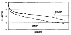
上記したように形成された燃料電池の液体燃料タンクに、純メタノールを10ml注入し、温度25℃、相対湿度50%の環境の下、単位面積あたりの電流量である電流密度(mA/cm2)と燃料電池の出力電圧(V)との関係を測定した。その結果を図3に示す。また、発電時間と発電開始時の燃料電池の出力電圧を100としたときの出力電圧率との関係を測定した。その結果を図4に示す。 10 ml of pure methanol is injected into the liquid fuel tank of the fuel cell formed as described above, and the current density (mA / cm 2) as a current amount per unit area under an environment of a temperature of 25 ° C. and a relative humidity of 50%. ) And the output voltage (V) of the fuel cell were measured. The result is shown in FIG. In addition, the relationship between the power generation time and the output voltage rate when the output voltage of the fuel cell at the start of power generation was set to 100 was measured. The result is shown in FIG.
(比較例1)
比較例1で使用された燃料電池は、燃料供給手段を有しないこと以外は、上記した実施例1で使用された燃料電池の構成と同じである。また、電流密度(mA/cm2)と燃料電池の出力電圧(V)との関係および発電時間と出力電圧率との関係を測定する際の測定方法および測定条件は、実施例1における測定方法および測定条件と同じである。電流密度(mA/cm2)と燃料電池の出力電圧(V)との関係を測定した結果を図3に示し、発電時間と出力電圧率との関係を測定した結果を図4に示す。
(Comparative Example 1)
The fuel cell used in Comparative Example 1 has the same configuration as that of the fuel cell used in Example 1 described above, except that it does not have fuel supply means. Further, the measurement method and measurement conditions for measuring the relationship between the current density (mA / cm 2 ) and the output voltage (V) of the fuel cell and the relationship between the power generation time and the output voltage rate are the measurement method in Example 1. And the measurement conditions are the same. The result of measuring the relationship between the current density (mA / cm 2 ) and the output voltage (V) of the fuel cell is shown in FIG. 3, and the result of measuring the relationship between the power generation time and the output voltage rate is shown in FIG.
(測定結果の検討)
図3に示すように、燃料電池の充電密度が高くなるに従って出力電圧が低下するが、その出力電圧の低下は、燃料供給手段を備える実施例1の燃料電池の方が少なく、高い発電出力が得られることがわかった。
(Examination of measurement results)
As shown in FIG. 3, the output voltage decreases as the charging density of the fuel cell increases. However, the output voltage decreases less in the fuel cell of Example 1 having the fuel supply means, and the high power generation output is higher. It turns out that it is obtained.
また、図4に示すように、双方とも発電時間に伴って、出力電圧率は減少するが、燃料供給手段を備える実施例1の燃料電池の方がその減少率が小さく、高い出力電圧を維持できることがわかった。 Further, as shown in FIG. 4, although both output voltage rates decrease with the power generation time, the fuel cell of Example 1 having the fuel supply means has a smaller decrease rate and maintains a high output voltage. I knew it was possible.
これらの測定結果から、燃料電池に燃料供給手段を設け、気液分離膜を介して行われる、アノード触媒層から拡散した水蒸気と液体燃料との間の熱交換を促進することで、優れた出力特性が得られることがわかった。 From these measurement results, the fuel cell is provided with a fuel supply means, which promotes heat exchange between the water vapor diffused from the anode catalyst layer and the liquid fuel, which is performed through the gas-liquid separation membrane. It was found that characteristics were obtained.
10…燃料電池、11…アノード触媒層、12…アノードガス拡散層、13…カソード触媒層、14…カソードガス拡散層、15…電解質膜、16…膜電極接合体、17…アノード導電層、18…カソード導電層、19…アノードシール材、20…カソードシール材、21…液体燃料タンク、22…気液分離膜、23,27…フレーム、24…水排出手段、25…気化燃料収容室、26…燃料供給手段、28…保湿層、29…表面層、30…空気導入口。
DESCRIPTION OF
Claims (6)
液体燃料を収容する燃料タンクと、
前記燃料タンクと前記膜電極接合体の燃料極側との間に配設され、前記燃料極から拡散した水蒸気と前記液体燃料との間の熱交換を行い、前記液体燃料の気化成分を前記燃料極側に通過させる気液分離層と
を具備することを特徴とする燃料電池。 A membrane electrode assembly composed of a fuel electrode, an air electrode, and an electrolyte membrane sandwiched between the fuel electrode and the air electrode;
A fuel tank containing liquid fuel;
The fuel tank is disposed between the fuel tank and the fuel electrode side of the membrane electrode assembly, performs heat exchange between the water vapor diffused from the fuel electrode and the liquid fuel, and converts the vaporized component of the liquid fuel into the fuel. A fuel cell comprising: a gas-liquid separation layer that is passed to the pole side.
Priority Applications (4)
| Application Number | Priority Date | Filing Date | Title |
|---|---|---|---|
| JP2005311251A JP2007122960A (en) | 2005-10-26 | 2005-10-26 | Fuel cell |
| US12/091,514 US20090263688A1 (en) | 2005-10-26 | 2006-10-20 | Fuel cell |
| PCT/JP2006/320943 WO2007049518A1 (en) | 2005-10-26 | 2006-10-20 | Fuel cell |
| TW095139205A TW200746535A (en) | 2005-10-26 | 2006-10-24 | Fuel cell |
Applications Claiming Priority (1)
| Application Number | Priority Date | Filing Date | Title |
|---|---|---|---|
| JP2005311251A JP2007122960A (en) | 2005-10-26 | 2005-10-26 | Fuel cell |
Publications (1)
| Publication Number | Publication Date |
|---|---|
| JP2007122960A true JP2007122960A (en) | 2007-05-17 |
Family
ID=37967630
Family Applications (1)
| Application Number | Title | Priority Date | Filing Date |
|---|---|---|---|
| JP2005311251A Pending JP2007122960A (en) | 2005-10-26 | 2005-10-26 | Fuel cell |
Country Status (4)
| Country | Link |
|---|---|
| US (1) | US20090263688A1 (en) |
| JP (1) | JP2007122960A (en) |
| TW (1) | TW200746535A (en) |
| WO (1) | WO2007049518A1 (en) |
Cited By (1)
| Publication number | Priority date | Publication date | Assignee | Title |
|---|---|---|---|---|
| WO2009093651A1 (en) * | 2008-01-23 | 2009-07-30 | Nec Corporation | Fuel cell and control method for same |
Families Citing this family (2)
| Publication number | Priority date | Publication date | Assignee | Title |
|---|---|---|---|---|
| JP5807207B2 (en) * | 2010-11-12 | 2015-11-10 | パナソニックIpマネジメント株式会社 | Method of operating polymer electrolyte fuel cell system and polymer electrolyte fuel cell system |
| FR2972303B1 (en) * | 2011-03-02 | 2013-11-15 | Commissariat Energie Atomique | FUEL CELL WITH ANODIC CHAMBER COMPRISING A WATER CONDENSING AND DRAINING SURFACE IN THE ANODIC CHAMBER, AND METHOD FOR CONDENSING AND DRAINING WATER FORMED IN SAID CHAMBER |
Citations (3)
| Publication number | Priority date | Publication date | Assignee | Title |
|---|---|---|---|---|
| JP2000268836A (en) * | 1999-03-15 | 2000-09-29 | Sony Corp | Powder generating device |
| JP2002373677A (en) * | 2001-06-15 | 2002-12-26 | Toshiba Corp | Fuel cell |
| WO2006040961A1 (en) * | 2004-10-08 | 2006-04-20 | Kabushiki Kaisha Toshiba | Fuel cell |
Family Cites Families (11)
| Publication number | Priority date | Publication date | Assignee | Title |
|---|---|---|---|---|
| US5364711A (en) * | 1992-04-01 | 1994-11-15 | Kabushiki Kaisha Toshiba | Fuel cell |
| US6326097B1 (en) * | 1998-12-10 | 2001-12-04 | Manhattan Scientifics, Inc. | Micro-fuel cell power devices |
| JP3765999B2 (en) * | 2000-06-30 | 2006-04-12 | 株式会社東芝 | Fuel cell |
| US7601448B2 (en) * | 2001-07-03 | 2009-10-13 | Sumitomo Chemical Company, Limited | Polymer electrolyte membrane and fuel cell |
| TW589760B (en) * | 2001-08-09 | 2004-06-01 | Sumitomo Chemical Co | Polymer electrolyte composition and fuel cell |
| DE10145875B4 (en) * | 2001-09-18 | 2010-09-16 | Daimler Ag | Membrane electrode unit for a self-humidifying fuel cell |
| JP2003317791A (en) * | 2002-04-24 | 2003-11-07 | Hitachi Maxell Ltd | Liquid fuel cell |
| JP3693039B2 (en) * | 2002-06-07 | 2005-09-07 | 日本電気株式会社 | Liquid fuel supply type fuel cell |
| DE10261482A1 (en) * | 2002-12-23 | 2004-07-01 | Basf Ag | Fuel cell module for polymer electrolyte membrane fuel cell stacks used e.g. in vehicles comprises a bipolar plate and a membrane-electrode unit |
| US20040209133A1 (en) * | 2003-04-15 | 2004-10-21 | Hirsch Robert S. | Vapor feed fuel cell system with controllable fuel delivery |
| US7846591B2 (en) * | 2004-02-17 | 2010-12-07 | Gm Global Technology Operations, Inc. | Water management layer on flowfield in PEM fuel cell |
-
2005
- 2005-10-26 JP JP2005311251A patent/JP2007122960A/en active Pending
-
2006
- 2006-10-20 US US12/091,514 patent/US20090263688A1/en not_active Abandoned
- 2006-10-20 WO PCT/JP2006/320943 patent/WO2007049518A1/en active Application Filing
- 2006-10-24 TW TW095139205A patent/TW200746535A/en not_active IP Right Cessation
Patent Citations (3)
| Publication number | Priority date | Publication date | Assignee | Title |
|---|---|---|---|---|
| JP2000268836A (en) * | 1999-03-15 | 2000-09-29 | Sony Corp | Powder generating device |
| JP2002373677A (en) * | 2001-06-15 | 2002-12-26 | Toshiba Corp | Fuel cell |
| WO2006040961A1 (en) * | 2004-10-08 | 2006-04-20 | Kabushiki Kaisha Toshiba | Fuel cell |
Cited By (1)
| Publication number | Priority date | Publication date | Assignee | Title |
|---|---|---|---|---|
| WO2009093651A1 (en) * | 2008-01-23 | 2009-07-30 | Nec Corporation | Fuel cell and control method for same |
Also Published As
| Publication number | Publication date |
|---|---|
| TW200746535A (en) | 2007-12-16 |
| TWI326932B (en) | 2010-07-01 |
| WO2007049518A1 (en) | 2007-05-03 |
| US20090263688A1 (en) | 2009-10-22 |
Similar Documents
| Publication | Publication Date | Title |
|---|---|---|
| TWI272739B (en) | Fuel cell | |
| JP2006269126A (en) | Fuel cell | |
| JP2006318712A (en) | Fuel cell | |
| JPWO2006101132A1 (en) | Fuel cell | |
| TWI332726B (en) | ||
| JP2010080173A (en) | Fuel cell | |
| JP2007095558A (en) | Fuel cell | |
| US20110275003A1 (en) | Fuel cell | |
| JP2008091291A (en) | Passive type fuel cell | |
| JP2009076451A (en) | Membrane-electrode assembly for fuel cell and fuel cell using same | |
| JP2007122960A (en) | Fuel cell | |
| JP2008293856A (en) | Fuel cell | |
| JP2007073349A (en) | Fuel cell | |
| JPWO2006085619A1 (en) | Fuel cell | |
| JP2008310995A (en) | Fuel cell | |
| JP2008293705A (en) | Membrane-electrode assembly, and fuel cell | |
| JPWO2008068887A1 (en) | Fuel cell | |
| JP2007164994A (en) | Fuel cell | |
| JP2008186799A (en) | Fuel cell | |
| JPWO2008068886A1 (en) | Fuel cell | |
| JP2009146864A (en) | Fuel cell | |
| JP2009021113A (en) | Fuel cell | |
| JP2007157593A (en) | Fuel cell | |
| JP2009170406A (en) | Fuel cell | |
| JP2009038014A (en) | Fuel cell and manufacturing method of fuel cell |
Legal Events
| Date | Code | Title | Description |
|---|---|---|---|
| A621 | Written request for application examination |
Free format text: JAPANESE INTERMEDIATE CODE: A621 Effective date: 20081022 |
|
| A131 | Notification of reasons for refusal |
Free format text: JAPANESE INTERMEDIATE CODE: A131 Effective date: 20120313 |
|
| A02 | Decision of refusal |
Free format text: JAPANESE INTERMEDIATE CODE: A02 Effective date: 20120703 |