JP2007120667A - Tripod-type constant velocity universal joint - Google Patents

Tripod-type constant velocity universal joint Download PDF

Info

Publication number
JP2007120667A
JP2007120667A JP2005315127A JP2005315127A JP2007120667A JP 2007120667 A JP2007120667 A JP 2007120667A JP 2005315127 A JP2005315127 A JP 2005315127A JP 2005315127 A JP2005315127 A JP 2005315127A JP 2007120667 A JP2007120667 A JP 2007120667A
Authority
JP
Japan
Prior art keywords
roller
universal joint
constant velocity
velocity universal
tripod
Prior art date
Legal status (The legal status is an assumption and is not a legal conclusion. Google has not performed a legal analysis and makes no representation as to the accuracy of the status listed.)
Withdrawn
Application number
JP2005315127A
Other languages
Japanese (ja)
Inventor
Daiji Okamoto
大路 岡本
Yoshihiko Hayama
佳彦 葉山
Current Assignee (The listed assignees may be inaccurate. Google has not performed a legal analysis and makes no representation or warranty as to the accuracy of the list.)
NTN Corp
Original Assignee
NTN Corp
NTN Toyo Bearing Co Ltd
Priority date (The priority date is an assumption and is not a legal conclusion. Google has not performed a legal analysis and makes no representation as to the accuracy of the date listed.)
Filing date
Publication date
Application filed by NTN Corp, NTN Toyo Bearing Co Ltd filed Critical NTN Corp
Priority to JP2005315127A priority Critical patent/JP2007120667A/en
Publication of JP2007120667A publication Critical patent/JP2007120667A/en
Withdrawn legal-status Critical Current

Links

Images

Abstract

<P>PROBLEM TO BE SOLVED: To make a vibration-proof material that is less likely to be peeled off, and to improve durability of a tripod-type constant velocity universal joint. <P>SOLUTION: The tripod-type constant velocity universal joint comprises an outer joint member 10, having three track grooves 12 formed in the inner periphery, an inner joint member 20, having three leg shafts 24 protruding in the radial direction, and a torque transmission element 30 rotatably, movably in the axial direction, and freely swivelably supported by each of the leg shafts 24 and stored in the track groove 12 of the outer joint member 10. The vibration-proof material 38 is assembled in the torque transmission element 30. <P>COPYRIGHT: (C)2007,JPO&INPIT

Description

この発明はトリポード型等速自在継手に関するもので、自動車や各種産業機械の動力伝達用に利用することができる。   The present invention relates to a tripod type constant velocity universal joint and can be used for power transmission of automobiles and various industrial machines.

特許文献1には、トリポード型等速自在継手の外輪を内側外筒と外側外筒と両者間に介在する防振材との組み合わせで構成し、内側外筒と外側外筒のいずれか一方の面に、両者間の間隙を狭める方向に突出した干渉部を設けることが記載されている。   In Patent Document 1, an outer ring of a tripod type constant velocity universal joint is configured by a combination of an inner outer cylinder, an outer outer cylinder, and a vibration isolating material interposed therebetween, and either one of the inner outer cylinder or the outer outer cylinder is used. It is described that the surface is provided with an interference portion protruding in the direction of narrowing the gap between them.

特許文献2には、トリポード型等速自在継手の外輪を内側外筒と外側外筒と両者間に介在する防振材との組み合わせで構成し、内側外筒と外側外筒の両端部に、両者間の間隙を狭める方向に突出した干渉部を設けることが記載されている。   In Patent Document 2, the outer ring of the tripod type constant velocity universal joint is configured by a combination of an inner outer cylinder, an outer outer cylinder, and a vibration isolating material interposed between both, and at both ends of the inner outer cylinder and the outer outer cylinder, It is described that an interference portion protruding in the direction of narrowing the gap between the two is provided.

特許文献3には、トリポード型等速自在継手の内径面の円周方向に干渉用突条を軸方向に沿って設け、内側外筒の外径面の周方向等分位置に各干渉用突条が回転方向に所要のすきまをおいてはまる干渉用嵌合溝を設け、干渉用突条相互間の外側外筒の内径面と干渉用突条相互間の内側外筒の外径面との間に防振材を介在させることが記載されている。
特開平2−168025号公報 特開平5−100343号公報 特開平3−272322号公報
In Patent Document 3, interference protrusions are provided along the axial direction in the circumferential direction of the inner diameter surface of the tripod type constant velocity universal joint, and each interference protrusion is provided at a circumferentially equal position on the outer diameter surface of the inner outer cylinder. An interference fitting groove is provided, in which the strip is provided with a required clearance in the rotation direction, and the inner diameter surface of the outer outer cylinder between the interference projections and the outer diameter surface of the inner outer cylinder between the interference projections. It describes that an anti-vibration material is interposed between them.
JP-A-2-16825 Japanese Patent Laid-Open No. 5-100343 JP-A-3-272322

従来の、外輪を内側外筒と外側外筒の組み合わせにより構成して両者間に防振材を介在させたトリポード型等速自在継手の場合、防振材がトルクをせん断力で受けもつ構造となる。このせん断力は、防振材の加硫接着を剥がす要因となる。防振材の加硫接着が剥がれてしまうと、トルク伝達装置としてのトリポード型等速自在継手が所期の機能を発揮し得ないこととなる。   In the case of a conventional tripod type constant velocity universal joint in which the outer ring is composed of a combination of an inner outer cylinder and an outer outer cylinder, and a vibration isolating material is interposed between the two, Become. This shearing force becomes a factor that peels off the vulcanized adhesion of the vibration isolator. If the vulcanization adhesion of the vibration isolator is peeled off, the tripod type constant velocity universal joint as the torque transmission device cannot perform the intended function.

この発明の主要な目的は、防振材を剥がれにくくしてトリポード型等速自在継手の耐久性を向上させることにある。   The main object of the present invention is to improve the durability of the tripod type constant velocity universal joint by making it difficult to peel off the vibration isolator.

この発明は、トリポード型等速自在継手の外輪と脚軸との間のトルク伝達要素に防振材を組み込み、防振材のトルク負荷方向に変位する圧縮力でトルクを受けもたせる、言い換えれば、防振材を圧縮する方向にトルクを作用させることにより、課題を解決したものである。   This invention incorporates a vibration isolator into the torque transmission element between the outer ring of the tripod type constant velocity universal joint and the leg shaft, and gives a torque with a compressive force displaced in the torque load direction of the vibration isolator, in other words, The problem is solved by applying a torque in the direction of compressing the vibration isolator.

すなわち、この発明のトリポード型等速自在継手は、内周に3本のトラック溝を有する外方継手部材と、半径方向に突出した3本の脚軸を有する内方継手部材と、各脚軸に回転、軸方向移動、首振り自在に担持され外方継手部材のトラック溝内に収容されたトルク伝達要素とを具備し、前記トルク伝達要素に防振材を組み込んだことを特徴とするものである。   That is, the tripod type constant velocity universal joint of the present invention includes an outer joint member having three track grooves on the inner periphery, an inner joint member having three leg shafts protruding in the radial direction, and each leg shaft. And a torque transmission element that is supported so as to be rotatable, axially movable, and swingable, and is accommodated in a track groove of an outer joint member, and a vibration isolating material is incorporated in the torque transmission element. It is.

請求項2の発明は、請求項1のトリポード型等速自在継手において、前記トルク伝達要素が、ニードルローラを介して相対回転自在の外ローラと内ローラとからなり、前記外ローラまたは内ローラが、相互間に防振材を介在させた同心円状の2以上の筒体で構成されていることを特徴とするものである。   According to a second aspect of the present invention, in the tripod type constant velocity universal joint according to the first aspect, the torque transmission element includes an outer roller and an inner roller that are relatively rotatable via a needle roller, and the outer roller or the inner roller is Further, it is characterized by being composed of two or more concentric cylinders with a vibration isolating material interposed between them.

防振材は筒体間に圧入してもよく(請求項3)、あるいは、筒体に加硫接着してもよい(請求項4)。   The vibration isolator may be press-fitted between the cylinders (Claim 3), or may be vulcanized and bonded to the cylinders (Claim 4).

請求項5の発明は、請求項1ないし4のいずれかのトリポード型等速自在継手において、過大な負荷を受け持つ干渉用突条を設けたことを特徴とするものである。   According to a fifth aspect of the present invention, in the tripod type constant velocity universal joint according to any one of the first to fourth aspects, an interference protrusion that handles an excessive load is provided.

請求項6の発明は、請求項5のトリポード型等速自在継手において、前記干渉用突条を前記外ローラまたは前記内ローラに一体的に設けたことを特徴とするものである。   The invention according to claim 6 is the tripod type constant velocity universal joint according to claim 5, wherein the interference protrusion is provided integrally with the outer roller or the inner roller.

請求項7の発明は、請求項5のトリポード型等速自在継手において、前記干渉用突条を外ローラと内ローラとの間に介在させたことを特徴とするものである。   A seventh aspect of the invention is the tripod type constant velocity universal joint according to the fifth aspect, wherein the interference protrusion is interposed between the outer roller and the inner roller.

請求項8の発明は、請求項1のトリポード型等速自在継手において、前記トルク伝達要素が、ニードルローラを介して相対回転自在の外ローラと内ローラとからなり、前記外ローラもしくは前記内ローラまたは両方を構成する材料を防振材としたことを特徴とするものである。   The invention according to claim 8 is the tripod type constant velocity universal joint according to claim 1, wherein the torque transmitting element is composed of an outer roller and an inner roller that are relatively rotatable via a needle roller, and the outer roller or the inner roller Or the material which comprises both is made into the vibration isolator, It is characterized by the above-mentioned.

この発明によれば、トリポード型等速自在継手の外輪と脚軸との間のトルク伝達要素に防振材を組み込むことにより、防振材を圧縮する方向にトルクが作用し、防振材が伝達トルクを圧縮力で受けもつことができるため、防振材が剥がれにくくなる。したがって、この発明によれば、トリポード型等速自在継手の耐久性が向上する。   According to the present invention, by incorporating the vibration isolator into the torque transmission element between the outer ring and the leg shaft of the tripod type constant velocity universal joint, torque acts in the direction of compressing the vibration isolator, Since the transmission torque can be handled by the compressive force, the vibration isolator is difficult to peel off. Therefore, according to the present invention, the durability of the tripod constant velocity universal joint is improved.

以下、図面に従ってこの発明の実施の形態を説明する。   Embodiments of the present invention will be described below with reference to the drawings.

まず、図9および図10を参照してトリポード型等速自在継手の基本構成を説明する。   First, the basic configuration of the tripod constant velocity universal joint will be described with reference to FIGS. 9 and 10.

図示するように、トリポード型等速自在継手は、外方継手部材としての外輪10と、内方継手部材としてのトリポード20と、トルク伝達要素としてのローラアセンブリ30を主要な構成要素として成り立っている。連結すべき2軸の一方を外輪10と接続し、他方をトリポード20と接続する。   As shown in the figure, the tripod type constant velocity universal joint includes an outer ring 10 as an outer joint member, a tripod 20 as an inner joint member, and a roller assembly 30 as a torque transmission element as main components. . One of the two shafts to be connected is connected to the outer ring 10 and the other is connected to the tripod 20.

図示する実施の形態では、外輪10は筒部と軸部とからなり、筒部は一端にて開口したカップ状である。筒部の内周には、円周三等分位置に3つのトラック溝12が形成してある。トラック溝12は軸方向に延びており、各トラック溝12の両側壁はローラ案内面14となっている。   In the illustrated embodiment, the outer ring 10 includes a cylindrical portion and a shaft portion, and the cylindrical portion has a cup shape opened at one end. Three track grooves 12 are formed on the inner circumference of the cylindrical portion at the circumference equally divided position. The track grooves 12 extend in the axial direction, and both side walls of each track groove 12 are roller guide surfaces 14.

トリポード20はセレーション(またはスプライン。以下同じ。)孔26を形成したボス22と、ボス22の円周三等分位置から半径方向に突出した脚軸24とからなる。各脚軸24はローラアセンブリ30を担持している。   The tripod 20 includes a boss 22 in which a serration (or spline, the same applies hereinafter) hole 26 is formed, and a leg shaft 24 that protrudes in a radial direction from the circumferential bisector of the boss 22. Each leg shaft 24 carries a roller assembly 30.

ローラアセンブリ30は外ローラ32と内ローラ34とからなる。すなわち、外ローラ32と内ローラ34は複数のニードルローラ36を介してユニット化され、相対回転可能なローラアセンブリを構成している。ローラアセンブリ30は外輪10のトラック溝12内に収容され、外ローラ34がローラ案内面14に沿って転動可能である。ローラ案内面14は外ローラ32の外周面に適合する凹曲面である。たとえば、ローラ案内面14を軸線が外輪10の軸線と平行な円筒面の一部で構成し、その断面形状を外ローラ32の外周面の母線に対応する円弧とする。   The roller assembly 30 includes an outer roller 32 and an inner roller 34. That is, the outer roller 32 and the inner roller 34 are unitized via a plurality of needle rollers 36 to constitute a roller assembly capable of relative rotation. The roller assembly 30 is accommodated in the track groove 12 of the outer ring 10, and the outer roller 34 can roll along the roller guide surface 14. The roller guide surface 14 is a concave curved surface that matches the outer peripheral surface of the outer roller 32. For example, the roller guide surface 14 is configured by a part of a cylindrical surface whose axis is parallel to the axis of the outer ring 10, and the cross-sectional shape thereof is an arc corresponding to the generatrix of the outer peripheral surface of the outer roller 32.

あるいは、外ローラ32の外周面を脚軸24の軸線から半径方向に離れた位置に曲率中心をもった円弧を母線とする凸曲面(トーラス面)とし、ローラ案内面14の断面形状はゴシックアーチ形状とする。これにより、外ローラ32の外周面とローラ案内面14とがアンギュラコンタクトをなす。球状の外ローラ外周面に対してローラ案内面14の断面形状をテーパ形状としても両者のアンギュラコンタクトが実現する。このように、外ローラ32の外周面とローラ案内面14とがアンギュラコンタクトをなす構成を採用することによって、ローラが振れにくくなるため姿勢が安定する。   Alternatively, the outer peripheral surface of the outer roller 32 is a convex curved surface (torus surface) having an arc having a center of curvature at a position radially away from the axis of the leg shaft 24, and the cross-sectional shape of the roller guide surface 14 is a Gothic arch. Shape. Thereby, the outer peripheral surface of the outer roller 32 and the roller guide surface 14 form an angular contact. Even if the cross-sectional shape of the roller guide surface 14 is tapered with respect to the outer peripheral surface of the spherical outer roller, the angular contact between them is realized. As described above, by adopting a configuration in which the outer peripheral surface of the outer roller 32 and the roller guide surface 14 form an angular contact, the roller is less likely to shake, so that the posture is stabilized.

内ローラ34は脚軸24の外周面に外嵌している。内ローラ34の円筒形外周面を内側軌道面とし、外ローラ32の円筒形内周面を外側軌道面として、これらの内外軌道面間にニードルローラ36が転動自在に介在する。図10(B)に示すように、ニードルローラ36は、できるだけ多くのころを入れた、保持器のない、いわゆる総ころ状態で組み込んである。符号38で指してあるのはニードルローラ36の抜け落ち止めのためのワッシャで、外ローラ32の端部内周面に形成した環状溝に装着してある。   The inner roller 34 is fitted on the outer peripheral surface of the leg shaft 24. With the cylindrical outer peripheral surface of the inner roller 34 as an inner raceway surface and the cylindrical inner peripheral surface of the outer roller 32 as an outer raceway surface, a needle roller 36 is interposed between these inner and outer raceway surfaces so as to be able to roll. As shown in FIG. 10B, the needle roller 36 is incorporated in a so-called all-roller state in which as many rollers as possible are inserted and there is no cage. Reference numeral 38 denotes a washer for preventing the needle roller 36 from coming off, and is attached to an annular groove formed on the inner peripheral surface of the end of the outer roller 32.

脚軸24の外周面は、縦断面(図9)で見ると脚軸24の軸線と平行なストレート形状であり、横断面(図10(A))で見ると、長軸が継手の軸線と直交する略楕円状である。脚軸の横断面形状は、トリポード20の軸方向で見た肉厚を減少させた略楕円状である。言い換えれば、脚軸の横断面形状は、トリポードの軸方向で互いに向き合った面が相互方向に、つまり、仮想円筒面よりも小径側に退避している。そのような形状の一具体例として略楕円状が挙げられる。略楕円状とは、字義どおりの楕円形のほか、一般に卵形、小判形などと称される形状も含まれる。これにより、脚軸24は、継手の軸線と直交する方向で内ローラ34の内周面と接触し、継手の軸線方向で内ローラ34の内周面との間にすきまを形成する。   The outer peripheral surface of the leg shaft 24 has a straight shape parallel to the axis of the leg shaft 24 when viewed in the longitudinal section (FIG. 9), and the long axis is the axis of the joint when viewed in the transverse section (FIG. 10A). It is a substantially elliptical shape that is orthogonal. The cross-sectional shape of the leg shaft is a substantially elliptical shape with a reduced thickness as viewed in the axial direction of the tripod 20. In other words, the cross-sectional shape of the leg shaft is such that the surfaces facing each other in the axial direction of the tripod are retracted in the mutual direction, that is, on the smaller diameter side than the virtual cylindrical surface. A specific example of such a shape is a substantially elliptical shape. The term “substantially oval” includes not only an elliptical shape as defined but also a shape generally called an oval shape or an oval shape. As a result, the leg shaft 24 comes into contact with the inner peripheral surface of the inner roller 34 in a direction perpendicular to the joint axis, and forms a gap between the leg shaft 24 and the inner peripheral surface of the inner roller 34 in the joint axial direction.

内ローラ34の内周面は円弧状凸断面を有する。すなわち、内周面の母線が半径rの凸円弧である(図10(C))。このことと、脚軸24の横断面形状が上述のように略楕円状であり、脚軸24と内ローラ34との間には所定のすきまが設けてあることから、内ローラ34は脚軸24の軸方向への移動が可能であるばかりでなく、脚軸24に対して首振り自在である。また、上述のとおり、内ローラ34と外ローラ32はニードルローラ36を介して相対回転自在にユニット化してあるため、脚軸24に対し、内ローラ34と外ローラ32がユニットとして首振り可能な関係にある。ここで、首振りとは、脚軸24の軸線を含む平面内で、脚軸24の軸線に対してローラアセンブリ(32,34)の軸線が傾くことをいう(図9参照)。   The inner peripheral surface of the inner roller 34 has an arcuate convex cross section. That is, the generatrix of the inner peripheral surface is a convex arc with a radius r (FIG. 10C). Since the cross-sectional shape of the leg shaft 24 is substantially elliptical as described above, and a predetermined clearance is provided between the leg shaft 24 and the inner roller 34, the inner roller 34 has a leg shaft. In addition to being able to move 24 in the axial direction, it can swing with respect to the leg shaft 24. As described above, since the inner roller 34 and the outer roller 32 are unitized so as to be relatively rotatable via the needle roller 36, the inner roller 34 and the outer roller 32 can swing as a unit with respect to the leg shaft 24. There is a relationship. Here, swinging means that the axis of the roller assembly (32, 34) is inclined with respect to the axis of the leg shaft 24 in a plane including the axis of the leg shaft 24 (see FIG. 9).

この実施の形態では、脚軸24の横断面形状を上述のようにしたことにより、継手が作動角をとったとき(図9)、ローラアセンブリの姿勢を変えることなく、脚軸24が外輪10に対して傾くことができる。また、内ローラ34の内周面が円弧状凸断面であることから、図10(C)に破線で示すように、両者の接触楕円が点に近いものとなり、同時に面積も小さくなる。したがって、ローラアセンブリ(32,34,36)を傾かせようとする摩擦モーメントが非常に低減する。また、ローラアセンブリの姿勢が常に安定し、ローラがローラ案内面と平行に保持されるため円滑に転動することができる。これにより、誘起スラストおよびスライド抵抗が低減し、かつ、それらの値のばらつきも小さくなる。   In this embodiment, since the cross-sectional shape of the leg shaft 24 is as described above, the leg shaft 24 can be connected to the outer ring 10 without changing the posture of the roller assembly when the joint takes an operating angle (FIG. 9). Can be tilted against. Further, since the inner peripheral surface of the inner roller 34 has an arcuate convex cross section, as shown by a broken line in FIG. 10C, the contact ellipse of both is close to a point, and the area is also reduced at the same time. Therefore, the frictional moment for tilting the roller assembly (32, 34, 36) is greatly reduced. Further, the posture of the roller assembly is always stable, and the roller is held parallel to the roller guide surface, so that it can roll smoothly. As a result, the induced thrust and slide resistance are reduced, and variations in their values are also reduced.

図11に示すトリポード型等速自在継手は、同じくダブルローラタイプであるが、脚軸24を球状にして、ローラアセンブリ30(32,34,36)の首振りは脚軸24と内ローラ34との間で行わせ、軸方向移動は外ローラ32と内ローラ34との間で行わせるようにしたものである。   The tripod type constant velocity universal joint shown in FIG. 11 is also a double roller type, but the leg shaft 24 is made spherical, and the swing of the roller assembly 30 (32, 34, 36) The movement in the axial direction is performed between the outer roller 32 and the inner roller 34.

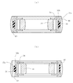
次に、図1を参照すると、ローラアセンブリ30の外ローラ32が同心円状の外側の筒体32aと内側の筒体32bに分割してあり、両者(32a,32b)間に防振材38が介在させてある。防振材38はゴムその他の弾性材料で形成してあり、筒体32a,32b間に圧入するか、加硫接着してある。   Next, referring to FIG. 1, the outer roller 32 of the roller assembly 30 is divided into a concentric outer cylindrical body 32a and an inner cylindrical body 32b, and a vibration isolating material 38 is provided between the two (32a, 32b). Intervened. The vibration isolator 38 is made of rubber or other elastic material and is press-fitted between the cylinders 32a and 32b or vulcanized and bonded.

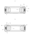
図2に示すように、内ローラ34を同心円状の筒体34a,34bに分割し、両者(34a,34b)間に防振材38を介在させてもよい。図面に例示したように内外2つの筒体に分割するほか、3以上の筒体に分割することもできる。また、外ローラ32と内ローラ34の両方に防振材38を組み込むことも可能であるが、少なくともどちらか一方に防振材38を組み込むことにより、外輪10と脚軸24との間の動力伝達経路でダンピング機能を発揮させることができる。   As shown in FIG. 2, the inner roller 34 may be divided into concentric cylindrical bodies 34a and 34b, and a vibration isolator 38 may be interposed between the both (34a and 34b). As illustrated in the drawing, it can be divided into two or more cylinders in addition to the inner and outer cylinders. Further, the vibration isolator 38 can be incorporated in both the outer roller 32 and the inner roller 34, but the power between the outer ring 10 and the leg shaft 24 can be obtained by incorporating the vibration isolator 38 in at least one of the rollers. A damping function can be exhibited in the transmission path.

図3に示す実施の形態は、ニードルローラ36を防振材で形成したものである。この場合も、外輪10と脚軸24との間の動力伝達経路でダンピング機能を発揮させることができる。   In the embodiment shown in FIG. 3, the needle roller 36 is formed of a vibration isolating material. Also in this case, the damping function can be exhibited in the power transmission path between the outer ring 10 and the leg shaft 24.

図4〜8は、図1の実施の形態の変形例に相当し、過大なトルクを防振材38に代わって負担する干渉用突条40を設けたものである。なお、図4〜8において、各図の右側の図(b)が過大トルク負荷時を示す。   4 to 8 correspond to modifications of the embodiment of FIG. 1, and are provided with an interference protrusion 40 that bears excessive torque in place of the vibration isolator 38. 4 to 8, the right side (b) of each figure shows the time of excessive torque load.

図4〜6に示す変形例は、内ローラ34の外周面に干渉用突条40が設けてある。すなわち、内ローラ34の外周面に環状溝を形成することにより、環状溝の両側に残った部分を干渉用突条40として利用する。この場合、防振材38は環状溝内にある。たとえばゴム製の防振材を環状溝の底面に加硫接着する。   In the modified examples shown in FIGS. 4 to 6, the interference protrusion 40 is provided on the outer peripheral surface of the inner roller 34. That is, by forming the annular groove on the outer peripheral surface of the inner roller 34, the portions remaining on both sides of the annular groove are used as the interference protrusion 40. In this case, the vibration isolator 38 is in the annular groove. For example, a rubber vibration isolator is vulcanized and bonded to the bottom surface of the annular groove.

図4の変形例の場合、外ローラ32の外側筒体32aの内周面と内側筒体32bの外周面が円筒面である。したがって、過大トルク負荷時には、図4(b)に示すように、外側筒体32aの内周面と内側筒体32bの外周面とが円筒面同士で干渉して、防振材38の異常変形を防止する。   In the modification of FIG. 4, the inner peripheral surface of the outer cylinder 32a and the outer peripheral surface of the inner cylinder 32b of the outer roller 32 are cylindrical surfaces. Therefore, at the time of excessive torque load, as shown in FIG. 4B, the inner peripheral surface of the outer cylindrical body 32a and the outer peripheral surface of the inner cylindrical body 32b interfere with each other and the abnormal deformation of the vibration isolator 38 is caused. To prevent.

図5の変形例の場合、外ローラ32の外側筒体32aの内周面と内側筒体32bの外周面が部分球面である。言い換えれば、外側筒体32aの内周面の母線および内側筒体32bの外周面の母線が中心軸線上に曲率中心をもった円弧である。したがって、過大トルク負荷時には、図5(b)に示すように、外側筒体32aの内周面と内側筒体32bの外周面とが球面同士で干渉する。   In the modification of FIG. 5, the inner peripheral surface of the outer cylindrical body 32a and the outer peripheral surface of the inner cylindrical body 32b of the outer roller 32 are partial spherical surfaces. In other words, the bus on the inner peripheral surface of the outer cylinder 32a and the bus on the outer peripheral surface of the inner cylinder 32b are arcs having a center of curvature on the central axis. Therefore, at the time of excessive torque load, as shown in FIG. 5B, the inner peripheral surface of the outer cylindrical body 32a and the outer peripheral surface of the inner cylindrical body 32b interfere with each other between the spherical surfaces.

図6の変形例の場合、外側筒体32aの内周面と内側筒体32bの外周面が円環状曲面(トーラス面)である。この場合、外側筒体32aの内周面の母線および内側筒体32bの外周面の母線は円弧であるが、曲率中心が中心軸線から離れた点に位置している。したがって、過大トルク負荷時には、図6(b)に示すように、外側筒体32aの内周面と内側筒体32bの外周面とが円環状曲面同士で干渉して、防振材38の異常変形を防止する。   In the modification of FIG. 6, the inner peripheral surface of the outer cylinder 32a and the outer peripheral surface of the inner cylinder 32b are annular curved surfaces (torus surfaces). In this case, the bus on the inner peripheral surface of the outer cylinder 32a and the bus on the outer peripheral surface of the inner cylinder 32b are arcs, but the center of curvature is located at a point away from the central axis. Therefore, at the time of excessive torque load, as shown in FIG. 6B, the inner peripheral surface of the outer cylindrical body 32a and the outer peripheral surface of the inner cylindrical body 32b interfere with each other between the annular curved surfaces, and the vibration isolator 38 is abnormal. Prevent deformation.

図7に示す変形例では、外ローラ32の外側筒体32aの内周面に干渉用突条40が設けてある。すなわち、外側筒体32aの内周面に環状溝を設けることにより、環状溝の両側に残った内周面を干渉用突条40としてある。そして、その環状溝に防振材38が取り付けてある。外側筒体32aの内周面と内側筒体32bの外周面は円筒面である。したがって、過大トルク負荷時には、図7(b)に示すように、外側筒体32aの内周面(=干渉用突条40)と内側筒体32bの外周面とが円筒面同士で干渉して、防振材38の異常変形を防止する。   In the modification shown in FIG. 7, the interference protrusion 40 is provided on the inner peripheral surface of the outer cylinder 32 a of the outer roller 32. That is, by providing an annular groove on the inner peripheral surface of the outer cylindrical body 32a, the inner peripheral surface remaining on both sides of the annular groove is used as the interference protrusion 40. And the vibration isolator 38 is attached to the annular groove. The inner peripheral surface of the outer cylindrical body 32a and the outer peripheral surface of the inner cylindrical body 32b are cylindrical surfaces. Therefore, at the time of excessive torque load, as shown in FIG. 7B, the inner peripheral surface (= interference protrusion 40) of the outer cylindrical body 32a and the outer peripheral surface of the inner cylindrical body 32b interfere with each other between the cylindrical surfaces. The abnormal deformation of the vibration isolator 38 is prevented.

図8に示す変形例の場合、外ローラ32の外側筒体32aの内周面と内側筒体32bの外周面がいずれも円筒面で、両者(32a,32b)間にリング状をした別体の干渉用突条40が介在させてある。ここでは内側筒体32b側に干渉用突条40を装着した場合が例示してあり、内側筒体32bの外周面に環状溝を形成して抜け止め用の止め輪33が装着してある。ここでも、過大トルク負荷時には、図8(b)に示すように、外側筒体32aの内周面と干渉用突条40とが円筒面同士で干渉して、防振材38の異常変形を防止する。   In the case of the modification shown in FIG. 8, the inner peripheral surface of the outer cylindrical body 32a and the outer peripheral surface of the inner cylindrical body 32b of the outer roller 32 are both cylindrical surfaces, and are separated from each other (32a, 32b). The interference protrusion 40 is interposed. Here, the case where the interference protrusion 40 is mounted on the inner cylinder 32b side is illustrated, and an annular groove is formed on the outer peripheral surface of the inner cylinder 32b, and a retaining ring 33 for retaining is mounted. Here too, when an excessive torque load is applied, as shown in FIG. 8B, the inner peripheral surface of the outer cylindrical body 32a and the interference protrusion 40 interfere with each other between the cylindrical surfaces, thereby causing abnormal deformation of the vibration isolator 38. To prevent.

図3の実施の形態を除き、防振材38は、全周にわたって挿入してもよく、あるいは、分割して挿入してもよい。   Except for the embodiment of FIG. 3, the vibration isolator 38 may be inserted over the entire circumference, or may be divided and inserted.

この発明の実施の形態を示すトリポード型等速自在継手の横断面図Cross-sectional view of tripod type constant velocity universal joint showing an embodiment of the present invention 別の実施の形態を示す図1と類似の横断面図Cross-sectional view similar to FIG. 1 showing another embodiment さらに別の実施の形態を示す図1と類似の横断面図Cross-sectional view similar to FIG. 1 showing still another embodiment (a)は図1の実施の形態の変形例を示すローラの断面図、(b)は過大負荷時のローラの断面図(A) is sectional drawing of the roller which shows the modification of embodiment of FIG. 1, (b) is sectional drawing of the roller at the time of excessive load (a)は図1の実施の形態の変形例を示すローラの断面図、(b)は過大負荷時のローラの断面図(A) is sectional drawing of the roller which shows the modification of embodiment of FIG. 1, (b) is sectional drawing of the roller at the time of excessive load (a)は図1の実施の形態の変形例を示すローラの断面図、(b)は過大負荷時のローラの断面図(A) is sectional drawing of the roller which shows the modification of embodiment of FIG. 1, (b) is sectional drawing of the roller at the time of excessive load (a)は図1の実施の形態の変形例を示すローラの断面図、(b)は過大負荷時のローラの断面図(A) is sectional drawing of the roller which shows the modification of embodiment of FIG. 1, (b) is sectional drawing of the roller at the time of excessive load (a)は図1の実施の形態の変形例を示すローラの断面図、(b)は過大負荷時のローラの断面図(A) is sectional drawing of the roller which shows the modification of embodiment of FIG. 1, (b) is sectional drawing of the roller at the time of excessive load トリポード型等速自在継手の縦断面図Vertical section of tripod type constant velocity universal joint (A)は図9のトリポード型等速自在継手の横断面図、(B)はローラアセンブリの横断面図、(C)は内ローラの縦断面図(A) is a cross-sectional view of the tripod type constant velocity universal joint of FIG. 9, (B) is a cross-sectional view of the roller assembly, and (C) is a vertical cross-sectional view of the inner roller. トリポード型等速自在継手の横断面図Cross section of tripod type constant velocity universal joint

符号の説明Explanation of symbols

10 外輪(外方継手部材)
12 トラック溝
14 ローラ案内面
20 トリポード(内方継手部材)
22 ボス
24 脚軸
26 セレーション孔
30 ローラアセンブリ(トルク伝達要素)
32 外ローラ
32a 外側筒体
32b 内側筒体
34 内ローラ
34a 外側筒体
34b 内側筒体
36 ニードルローラ
33 ワッシャ
38 防振材
40 干渉用突条
10 Outer ring (outer joint member)
12 Track groove 14 Roller guide surface 20 Tripod (inner joint member)
22 Boss 24 Leg shaft 26 Serration hole 30 Roller assembly (torque transmission element)
32 Outer roller 32a Outer cylinder 32b Inner cylinder 34 Inner roller 34a Outer cylinder 34b Inner cylinder 36 Needle roller 33 Washer 38 Anti-vibration material 40 Interference protrusion

Claims (8)

内周に3本のトラック溝を有する外方継手部材と、半径方向に突出した3本の脚軸を有する内方継手部材と、各脚軸に回転、軸方向移動、首振り自在に担持され外方継手部材のトラック溝内に収容されたトルク伝達要素とを具備し、前記トルク伝達要素に防振材を組み込んだトリポード型等速自在継手。   An outer joint member having three track grooves on the inner periphery, an inner joint member having three leg shafts projecting in the radial direction, and supported by each leg shaft so as to be rotatable, axially movable, and swingable. A tripod type constant velocity universal joint comprising a torque transmission element housed in a track groove of an outer joint member and incorporating a vibration isolating material into the torque transmission element. 前記トルク伝達要素が、ニードルローラを介して相対回転自在の外ローラと内ローラとからなり、前記外ローラまたは内ローラが、相互間に防振材を介在させた同心円状の2以上の筒体で構成されている請求項1のトリポード型等速自在継手。   The torque transmission element includes an outer roller and an inner roller that are rotatable relative to each other via a needle roller, and the outer roller or the inner roller has two or more concentric cylindrical bodies with a vibration isolating material interposed therebetween. The tripod type constant velocity universal joint of Claim 1 comprised by these. 前記防振材を前記筒体間に圧入した請求項2のトリポード型等速自在継手。   The tripod constant velocity universal joint according to claim 2, wherein the vibration isolator is press-fitted between the cylindrical bodies. 前記防振材を前記筒体に加硫接着した請求項2のトリポード型等速自在継手。   The tripod constant velocity universal joint according to claim 2, wherein the vibration isolator is vulcanized and bonded to the cylindrical body. 過大な負荷を受け持つ干渉用突条を設けた請求項1ないし4のいずれかのトリポード型等速自在継手。   The tripod type constant velocity universal joint according to any one of claims 1 to 4, further comprising an interference protrusion that handles an excessive load. 前記干渉用突条を前記外ローラまたは前記内ローラに一体的に設けた請求項5のトリポード型等速自在継手。   The tripod type constant velocity universal joint according to claim 5, wherein the interference protrusion is provided integrally with the outer roller or the inner roller. 前記干渉用突条を外ローラと内ローラとの間に介在させた請求項5のトリポード型等速自在継手。   6. The tripod constant velocity universal joint according to claim 5, wherein the interference protrusion is interposed between an outer roller and an inner roller. 前記トルク伝達要素が、ニードルローラを介して相対回転自在の外ローラと内ローラとからなり、前記外ローラもしくは前記内ローラまたは両方を構成する材料を防振材とした請求項1のトリポード型等速自在継手。   The tripod type according to claim 1, wherein the torque transmitting element is composed of an outer roller and an inner roller which are rotatable relative to each other via a needle roller, and the material constituting the outer roller or the inner roller or both is a vibration isolator. Fast universal joint.
JP2005315127A 2005-10-28 2005-10-28 Tripod-type constant velocity universal joint Withdrawn JP2007120667A (en)

Priority Applications (1)

Application Number Priority Date Filing Date Title
JP2005315127A JP2007120667A (en) 2005-10-28 2005-10-28 Tripod-type constant velocity universal joint

Applications Claiming Priority (1)

Application Number Priority Date Filing Date Title
JP2005315127A JP2007120667A (en) 2005-10-28 2005-10-28 Tripod-type constant velocity universal joint

Publications (1)

Publication Number Publication Date
JP2007120667A true JP2007120667A (en) 2007-05-17

Family

ID=38144730

Family Applications (1)

Application Number Title Priority Date Filing Date
JP2005315127A Withdrawn JP2007120667A (en) 2005-10-28 2005-10-28 Tripod-type constant velocity universal joint

Country Status (1)

Country Link
JP (1) JP2007120667A (en)

Cited By (4)

* Cited by examiner, † Cited by third party
Publication number Priority date Publication date Assignee Title
JP2010281357A (en) * 2009-06-03 2010-12-16 Jtekt Corp Sliding tripod type constant velocity joint
DE102007054563B4 (en) * 2007-11-15 2014-12-18 Volkswagen Ag tripod
DE102016222521A1 (en) * 2016-11-16 2018-05-17 Volkswagen Aktiengesellschaft tripod
CN110107610A (en) * 2019-04-30 2019-08-09 安徽理工大学 Submissive constant moment of force shaft coupling

Cited By (5)

* Cited by examiner, † Cited by third party
Publication number Priority date Publication date Assignee Title
DE102007054563B4 (en) * 2007-11-15 2014-12-18 Volkswagen Ag tripod
JP2010281357A (en) * 2009-06-03 2010-12-16 Jtekt Corp Sliding tripod type constant velocity joint
DE102016222521A1 (en) * 2016-11-16 2018-05-17 Volkswagen Aktiengesellschaft tripod
CN110107610A (en) * 2019-04-30 2019-08-09 安徽理工大学 Submissive constant moment of force shaft coupling
CN110107610B (en) * 2019-04-30 2020-06-05 安徽理工大学 Flexible constant moment coupling

Similar Documents

Publication Publication Date Title
JP2007120667A (en) Tripod-type constant velocity universal joint
JP4527581B2 (en) Constant velocity universal joint with boots
JP4794867B2 (en) Constant velocity universal joint with boots
JP2008261391A (en) Tripod type constant velocity universal joint
JP2005133917A (en) Isolation pulley
WO2006085418A1 (en) Constant velocity universal joint and boot for the same
JP4255678B2 (en) Tripod type constant velocity universal joint
JP2007120666A (en) Tripod-type constant velocity universal joint
JP2004257418A (en) Tripod uniform velocity universal joint
JP4946473B2 (en) Ball type constant velocity joint
JP3821914B2 (en) Elastic shaft coupling
JP2007120664A (en) Tripod-type constant velocity universal joint
JP2006258122A (en) Slide type constant velocity universal joint
JP2007211804A (en) Constant velocity universal joint
JP2012013207A (en) Tripod type constant velocity joint
JP2008215518A (en) Sliding system constant velocity universal joint
JP2009014179A (en) Tripod-type constant velocity universal joint
JP2007120543A (en) Tripod-type constant velocity universal joint
JP2007263235A (en) Constant velocity universal joint
JP2006283831A (en) Constant velocity universal joint
JP4178613B2 (en) Tripod type constant velocity joint
JP2017020581A (en) Ball bearing for pull-type clutch release bearing device
JP2017061990A (en) Boot for constant velocity universal joint and constant velocity universal joint having the same
JP2004116690A (en) Spider universal joint
JP2004068871A (en) Cross shaft joint

Legal Events

Date Code Title Description
A300 Withdrawal of application because of no request for examination

Free format text: JAPANESE INTERMEDIATE CODE: A300

Effective date: 20090106