JP2007115595A - Lighting apparatus - Google Patents
Lighting apparatus Download PDFInfo
- Publication number
- JP2007115595A JP2007115595A JP2005307561A JP2005307561A JP2007115595A JP 2007115595 A JP2007115595 A JP 2007115595A JP 2005307561 A JP2005307561 A JP 2005307561A JP 2005307561 A JP2005307561 A JP 2005307561A JP 2007115595 A JP2007115595 A JP 2007115595A
- Authority
- JP
- Japan
- Prior art keywords
- emitting diode
- light emitting
- light
- translucent case
- color
- Prior art date
- Legal status (The legal status is an assumption and is not a legal conclusion. Google has not performed a legal analysis and makes no representation as to the accuracy of the status listed.)
- Pending
Links
Images


Abstract
Description
本発明は、光源に発光ダイオードを用いた照明装置に関する。とくに、従来用いられている蛍光ランプと代替可能な照明装置に関する。 The present invention relates to a lighting device using a light emitting diode as a light source. In particular, the present invention relates to an illuminating device that can replace a conventionally used fluorescent lamp.
従来、一般に家庭用照明装置として蛍光ランプが用いられている(例えば、特許文献1を参照。)。蛍光ランプは、白熱電球に比べ効率がよく、また長寿命であるなどの特性を有しているために、幅広く使用されている。 Conventionally, a fluorescent lamp is generally used as a home lighting device (see, for example, Patent Document 1). Fluorescent lamps are widely used because they have characteristics such as higher efficiency and longer life than incandescent bulbs.
しかしながら、蛍光ランプには微量ではあるが水銀が使用されている。水銀は、妊娠中に摂取した場合には胎児に悪影響が出ることが報告されており、また、一般の人が摂取した場合には、神経障害が発生することも報告されている。それゆえ、近年の環境への意識向上により、ヨーロッパにおいてRoHS(Restriction of the use of certain Hazardous Substance in electrical and electronic equipment)指令が発行される見込みであり、その使用が制限されつつある。 However, mercury is used in fluorescent lamps, though in a very small amount. Mercury has been reported to adversely affect the fetus when ingested during pregnancy, and neuropathy has been reported to occur when ingested by the general population. Therefore, in recent years, due to the increased awareness of the environment, it is expected that the RoHS (the Restriction of the Use of Hazardous Substantial in electrical and electrical equipment) Directive will be issued in Europe.
また、蛍光ランプは、白熱電球より寿命が長いものの、6000時間程度とその値は十分なものではなく、しばしばその交換が必要である。それにもかかわらず、今後蛍光ランプの寿命が大幅に改善される可能性は低い。さらに、蛍光ランプは、さらなる高効率化がすすめられているが、やはり劇的に改善される可能性は低い。すなわち、蛍光ランプの性能改善は限界にきているといえる。このような実状に鑑みてか、光源に発光ダイオードを用いた照明装置も提案されている。 In addition, fluorescent lamps have a longer lifetime than incandescent bulbs, but their values are not sufficient, about 6000 hours, and often need to be replaced. Nevertheless, it is unlikely that the lifetime of the fluorescent lamp will be significantly improved in the future. In addition, fluorescent lamps are being promoted to be more efficient, but they are also unlikely to be dramatically improved. In other words, it can be said that the improvement of the performance of the fluorescent lamp has reached its limit. In view of such a situation, an illumination device using a light emitting diode as a light source has been proposed.
例えば、特許文献2には、内面又は外面に蛍光体を塗布した蛍光管状体と、複数の紫外線発光素子を基板上に配置した紫外線発光ダイオード基板と、紫外線発光ダイオード基板を蛍光管状体の内部に支持する支持手段と、紫外線発光素子に電力を供給するリード線とを備えた照明管が記載されている。これにより、製作が容易で長期間の使用に耐えうる照明装置を提供することが可能になるとされている。
For example, in
しかし、特許文献2の照明管は、外部電力をそのまま発光ダイオードに供給するものとなっており、部屋の天井などに設けられた蛍光ランプ用の支持具にそのまま取り付けて使用できる構造とはなっていない。このため、特許文献2の照明管は、蛍光ランプからの置き換えが容易なものとはなっていない。
However, the illumination tube of
本発明は、上記課題を解決するためになされたものであり、水銀による害がなく、長寿命で、高効率な照明装置を提供することを目的とする。また、蛍光ランプからの置き換えが容易な照明装置を提供することも本発明の目的である。 The present invention has been made to solve the above-described problems, and an object of the present invention is to provide a lighting device that is free from mercury, has a long life, and is highly efficient. It is another object of the present invention to provide an illumination device that can be easily replaced with a fluorescent lamp.
上記課題は、発光ダイオードと、該発光ダイオードを収容するための透光ケースと、外部電力を透光ケースの内部に導入するための電極部と、該電極部から導入された電流電圧を変換して前記発光ダイオードへ供給する内部電源とを備えたことを特徴とする照明装置を提供することによって解決される。 The above problems include a light emitting diode, a translucent case for housing the light emitting diode, an electrode unit for introducing external power into the translucent case, and a current voltage introduced from the electrode unit. This is solved by providing an illuminating device comprising an internal power supply for supplying to the light emitting diode.
これにより、商用電源などから供給された外部電力を内部電源で変換してから発光ダイオードに供給することが可能になり、発光ダイオードを適切な電流電圧で駆動することができる。また、透光ケースによって、発光ダイオードを埃や湿気などから保護することもできる。 As a result, it is possible to supply external light supplied from a commercial power supply or the like to the light emitting diode after being converted by the internal power supply, and the light emitting diode can be driven with an appropriate current voltage. In addition, the light-emitting diode can be protected from dust and moisture by the translucent case.
ここで、透光ケースとは、全体が透光性を有する材料で形成されたものだけでなく、一部が透光性を有する材料で形成されたもの(一部が透光性を有さない材料で形成されたもの)をも含む概念であるとする。透光ケースの透光部は、通常、ガラスや樹脂などによって形成される。 Here, the translucent case is not only entirely formed of a material having translucency, but also partially formed of a material having translucency (some have translucency). It is assumed that the concept also includes those formed of no material. The translucent part of the translucent case is usually formed of glass or resin.
上記の照明装置において、前記発光ダイオードが、0℃における熱伝導率が200W・m−1・K−1以上の金属で形成された基板に実装されていると好ましい。これにより、発光ダイオードから発せられた熱を効率的に逃すことが可能になる。0℃における熱伝導率が200W・m−1・K−1以上の金属としては、アルミニウム(236W・m−1・K−1)や、銅(403W・m−1・K−1)などが例示される。 In the lighting device, the light-emitting diode is preferably mounted on a substrate formed of a metal having a thermal conductivity at 0 ° C. of 200 W · m −1 · K −1 or more. This makes it possible to efficiently release the heat generated from the light emitting diode. Examples of the metal having a thermal conductivity at 0 ° C. of 200 W · m −1 · K −1 or more include aluminum (236 W · m −1 · K −1 ) and copper (403 W · m −1 · K −1 ). Illustrated.
複数の前記発光ダイオードが、アレイ状に配置されることも好ましい。また、前記透光ケースが円筒状(直管状)に形成され、前記電極部が透光ケースの両端に設けられることも好ましい。これにより、本発明の照明装置を直管蛍光ランプの代替品として用いることが可能になる。 It is also preferable that the plurality of light emitting diodes are arranged in an array. Moreover, it is also preferable that the translucent case is formed in a cylindrical shape (straight tube) and the electrode portions are provided at both ends of the translucent case. This makes it possible to use the illumination device of the present invention as an alternative to a straight tube fluorescent lamp.
前記透光ケースの一部を金属によって形成し、前記発光ダイオードから発せられた熱が透光ケースの外部へ放出されやすくすることも好ましい。これにより、発光ダイオードや内部電源の故障を防ぐことが可能になる。 It is also preferable that a part of the translucent case is made of metal so that heat generated from the light emitting diode is easily released to the outside of the translucent case. Thereby, it becomes possible to prevent a failure of the light emitting diode and the internal power supply.
前記透光ケースが、前記発光ダイオードから出射された光を拡散させるための拡散手段を備えていることも好ましい。これにより、発光ダイオードから出射された光を均一にかつ広範囲に拡散することができるようになる。 It is also preferable that the translucent case includes a diffusing unit for diffusing the light emitted from the light emitting diode. As a result, the light emitted from the light emitting diode can be diffused uniformly and over a wide range.
前記発光ダイオードの光源色は、特に限定されないが、JISZ9112「蛍光ランプの光源色及び演色性による区分」の4.2「色度範囲」に規定された昼光色、昼白色、白色、温白色又は電球色であると好ましい。これにより、照射光の色度を一般的な蛍光ランプの照射光と同等に設定することが可能になる。 The light source color of the light emitting diode is not particularly limited, but it is a daylight color, day white color, white color, warm white color or light bulb defined in 4.2 “Chromaticity range” of JISZ9112 “Classification by light source color and color rendering of fluorescent lamp” A color is preferred. As a result, the chromaticity of the irradiation light can be set to be equivalent to the irradiation light of a general fluorescent lamp.
本発明の照明装置を、JISC7617−2「直管蛍光ランプ−第2部:性能規定」の2.3.1「データシートのリスト」に規定された直管蛍光ランプのいずれかと同じ寸法に形成し、直管蛍光ランプと置き換え可能なものとすることも好ましい。これにより、本発明の照明装置を直管蛍光ランプ用の支持具にそのまま取り付けて使用することが可能になる。したがって、置き換えのコストを低減するだけでなく、資源を有効に活用することも可能になる。 The lighting device of the present invention is formed to have the same dimensions as any of the straight tube fluorescent lamps defined in 2.3.1 “List of data sheets” of JIS C7617-2 “Straight tube fluorescent lamps—Part 2: Specification of performance”. However, it is also preferable to be able to replace the straight tube fluorescent lamp. As a result, the lighting device of the present invention can be used as it is attached to a support for a straight tube fluorescent lamp. Therefore, not only the replacement cost can be reduced, but also resources can be used effectively.
以上のように、本発明によって、水銀による害がなく、長寿命で、高効率な照明装置を提供することが可能になる。また、蛍光ランプからの置き換えが容易な照明装置を提供することも可能になる。 As described above, according to the present invention, it is possible to provide an illumination device that is free from mercury and has a long lifetime and high efficiency. It is also possible to provide an illumination device that can be easily replaced with a fluorescent lamp.
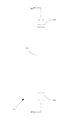
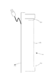
本発明の照明装置を、図面を用いてより具体的に説明する。図1は、本発明の照明装置の第一実施例を示した外観図である。図2は、図1に示された照明装置のA−A’断面図である。図3は、図1に示された照明装置を直管蛍光ランプ用の支持具に取り付けた状態を示した外観図である。 The lighting device of the present invention will be described more specifically with reference to the drawings. FIG. 1 is an external view showing a first embodiment of a lighting device according to the present invention. FIG. 2 is a cross-sectional view taken along line A-A ′ of the lighting device illustrated in FIG. 1. FIG. 3 is an external view showing a state in which the lighting device shown in FIG. 1 is attached to a support for a straight tube fluorescent lamp.
[第一実施例]
まず、本発明の照明装置の第一実施例について説明する。第一実施例の照明装置1は、図1に示すように、電極部2、透光ケース3から構成されている。また、図2に示すように、発光ダイオード4、基板5、内部電源6、拡散シート7(拡散手段)、支持部8が透光ケース3の内部に配置されている。
[First embodiment]
First, the 1st Example of the illuminating device of this invention is described. As shown in FIG. 1, the
電極部2は、一般的な直管蛍光ランプに用いられているものと同機構で同寸法のものとなっている。また、透光ケース3の外径と長さも、一般的な直管蛍光ランプと同じ寸法となっている。したがって、照明装置1は、一般的な直管蛍光ランプ用の支持具に搭載することが可能となっている。
The
透光ケース3は、透明なガラス又はアクリルによって形成されており、発光ダイオード4から出射された光を外部へ透過させることができるようになっている。発光ダイオード4は、第一実施例において、5個使用されている。発光ダイオード4の個数はこの数に限定されるものではなく必要に応じて増減してよい。また、発光ダイオード4の色度は、白色、昼光色などが適当である。第一実施例の照明装置1においては、発光ダイオード4としていわゆるハイパワーLEDを用いている。
The
基板5は、金属で形成されており、支持部8に固定されている。基板5としては、一般にはアルミニウムで形成されたものが使われる。その理由は、安価であること、比較的熱伝導率がよく放熱特性がよいことなどである。このため、第一実施例の照明装置1においても、アルミニウムで形成された基板5を用いている。
The
しかしながら、発光ダイオード4の消費電力が大きく、発熱量が問題となる場合には、発光ダイオード4の発光効率が低下するだけでなく、発光ダイオード4が故障するおそれもある。このような場合には、アルミニウムよりも熱伝導性に優れた銅で基板5を形成すると好ましい。これにより、発光ダイオード4から発せられた熱をより速やかに逃すことが可能になり、照明装置1の性能や信頼性を向上させることができる。
However, when the power consumption of the
内部電源6は、電極部2から導入された外部電力を入力として受け取る。この外部電力は蛍光ランプを点灯するためのものであり、当然のことながら発光ダイオード4を点灯させるのにそのまま使用することができない。そこで、内部電源6において、発光ダイオード4を点灯させるのに適した直流電流、直流電圧に変換するようにしている。
The
拡散シート7は、拡散手段として用いている。拡散シート7は、発光ダイオード4から発せられた光を拡散する。発光ダイオード4から発せられた光は、指向性が強く、局所的にしか光を照射することができない。このため、発光ダイオード4から発せられた光を拡散シート7で拡散することによって、光の指向性を弱め、広い面積に均一に光を照射することができるようにしている。
The
以上で説明した第一実施例の照明装置1は、図3に示すように、直管蛍光ランプから容易に置き換えることができるものとなっている。図3の例では、照明装置1を20Wの直管蛍光ランプと同寸法に製作しており、20Wの直管蛍光ランプ用の支持具31に取り付けている。
The
発光ダイオード4の発光効率は、現状でも、60lm/W程度であり、蛍光ランプの発光効率(80lm/W)に迫ってきている。発光ダイオード4の発光効率は、2〜3年後には蛍光ランプのそれを上回ると予想されている。このため、将来的には、蛍光ランプよりも明るい照明装置1が登場することも大いに期待できる。
The light emission efficiency of the
また、発光ダイオード4の寿命は50000時間以上であり、蛍光ランプの寿命(6000時間程度)に比べ、非常に長くなっている。このため、照明装置1は、交換にかかる労力やコストを大幅に削減できるものとなっている。
The life of the
さらに、蛍光ランプには微量ではあるが、水銀が使用さている。近年の、環境への意識向上により、胎児や、成人の神経系に悪影響を及ぼす水銀の使用が全世界的に規制されてきている(ヨーロッパにおけるRoHS指令など)。一方、本発明の照明装置1は、水銀不使用であり、非常に環境に優しいものとなっている。
In addition, mercury is used in fluorescent lamps, although only in trace amounts. In recent years, the use of mercury that adversely affects the nervous system of fetuses and adults has been regulated worldwide due to an increase in environmental awareness (such as the RoHS directive in Europe). On the other hand, the
[第二実施例]
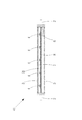
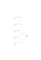
続いて、本発明の照明装置の第二実施例について説明する。図4は、本発明の照明装置の第二実施例を示した外観図である。図5は、図4に示された照明装置のB−B’断面図である。図6は、図5に示された基板を上方から見た図である。
[Second Example]
Then, the 2nd Example of the illuminating device of this invention is described. FIG. 4 is an external view showing a second embodiment of the illumination device of the present invention. FIG. 5 is a cross-sectional view of the lighting device BB ′ shown in FIG. FIG. 6 is a view of the substrate shown in FIG. 5 as viewed from above.
第二実施例の照明装置41は、図5と図6に示すように、各発光ダイオード4を実装する基板51が一体的に形成されている点で第一実施例の照明装置1と異なっている。この基板51の上部には、複数の発光ダイオード4をアレイ上に配置することができるようになっている。このような構成にすることにより、支持部8に基板51を取り付ける作業が簡便になり、製作コストを低減することができる。また、照明装置41の長手方向に熱を伝わせることも可能になる。
As shown in FIGS. 5 and 6, the
他の部分については、第一実施例の照明装置1と略同様であるために、説明を割愛する。
The other parts are substantially the same as those of the
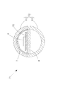
[第三実施例]
続いて、本発明の照明装置の第三実施例について説明する。図7は、本発明の照明装置の第三実施例を示した外観図である。図8は、図7に示された照明装置のC−C’断面図である。図9は、図8に示された照明装置のD−D’断面図である。
[Third embodiment]
Then, the 3rd Example of the illuminating device of this invention is described. FIG. 7 is an external view showing a third embodiment of the illumination device of the present invention. 8 is a cross-sectional view taken along the line CC ′ of the lighting device shown in FIG. 9 is a cross-sectional view taken along the line DD ′ of the lighting device shown in FIG.
第三実施例の照明装置71は、透光ケース72が複数のパーツで構成されている点で
第一実施例及び第二実施例の照明装置1,41と異なっている。図7〜図9に示す透光ケース72は、2つのパーツで構成されており、透明なガラス又はアクリルで形成された透光部81と、金属で形成された金属部82(非透光部)を組み合わせたものとなっている。透光部81は、発光ダイオード4の光の出射方向に設けられている。
The illuminating
また、金属部82は、図9に示すように、熱伝導性に優れた金属製の支持部8を介して基板51と接続されている。このため、発光ダイオード4から発せられた熱は、支持部8を通って金属部82に到達し、金属部82から透光ケース72の外部に放出されるようになっている。したがって、発光ダイオード4の温度上昇を防ぎやすく、発光ダイオード4の輝度や寿命に対して良い効果を与えることが可能となっている。
Moreover, the
他の部分については、第二実施例の照明装置41と略同様であるために、説明を割愛する。
The other parts are substantially the same as those of the
[その他]
なお、本発明の照明装置は、上記実施例に限定されるものではなく、本発明の趣旨を逸脱しない範囲で自由に変形して実施することができる。例えば、発光ダイオード4の光源色を、グリーンやブルーなどにして、光イルミネーションを楽しむことも可能である。
[Others]
In addition, the illuminating device of this invention is not limited to the said Example, It can deform | transform and implement freely within the range which does not deviate from the meaning of this invention. For example, it is also possible to enjoy light illumination by setting the light source color of the
また、透光ケースを円環状に形成することにより、環形蛍光ランプの代替照明とすることも可能である。 In addition, by forming the translucent case in an annular shape, it is possible to provide alternative illumination for the annular fluorescent lamp.
さらに、透光ケースの金属部に冷却用のヒートシンクを取り付けてもよい。このようにすることにより、効率的に排熱を行うことができる。 Furthermore, a heat sink for cooling may be attached to the metal part of the translucent case. By doing in this way, exhaust heat can be performed efficiently.
1,41,71 照明装置
2 電極部
3,72 透光ケース
4 発光ダイオード
5,51 基板
6 内部電源
7 拡散シート(拡散手段)
8 支持部
31 支持具
81 透光部
82 金属部(非透光部)
DESCRIPTION OF
8 Supporting
Claims (8)
Priority Applications (1)
| Application Number | Priority Date | Filing Date | Title |
|---|---|---|---|
| JP2005307561A JP2007115595A (en) | 2005-10-21 | 2005-10-21 | Lighting apparatus |
Applications Claiming Priority (1)
| Application Number | Priority Date | Filing Date | Title |
|---|---|---|---|
| JP2005307561A JP2007115595A (en) | 2005-10-21 | 2005-10-21 | Lighting apparatus |
Publications (1)
| Publication Number | Publication Date |
|---|---|
| JP2007115595A true JP2007115595A (en) | 2007-05-10 |
Family
ID=38097584
Family Applications (1)
| Application Number | Title | Priority Date | Filing Date |
|---|---|---|---|
| JP2005307561A Pending JP2007115595A (en) | 2005-10-21 | 2005-10-21 | Lighting apparatus |
Country Status (1)
| Country | Link |
|---|---|
| JP (1) | JP2007115595A (en) |
Cited By (6)
| Publication number | Priority date | Publication date | Assignee | Title |
|---|---|---|---|---|
| DE102008020776A1 (en) | 2007-04-25 | 2008-10-30 | Denso Corp., Kariya-shi | A sensor device for detecting changes in a dynamic quantity and at the same time suppressing detection deviations caused by bending deformation of a sensor chip |
| JP2012009316A (en) * | 2010-06-25 | 2012-01-12 | World Electronic Co Ltd | Led illumination lamp |
| JP2013127764A (en) * | 2011-12-19 | 2013-06-27 | Fukuo Hino | Evacuation display pole as "visible guide post" and evacuation route guidance system |
| CN103292178A (en) * | 2013-05-16 | 2013-09-11 | 常州市亮泰照明电器有限公司 | Multifunctional replaceable illuminating lamp |
| JP2015165511A (en) * | 2008-09-29 | 2015-09-17 | エルジー イノテック カンパニー リミテッド | Light-emitting apparatus |
| JP2018049844A (en) * | 2008-08-11 | 2018-03-29 | アイリスオーヤマ株式会社 | Luminaire |
-
2005
- 2005-10-21 JP JP2005307561A patent/JP2007115595A/en active Pending
Cited By (8)
| Publication number | Priority date | Publication date | Assignee | Title |
|---|---|---|---|---|
| DE102008020776A1 (en) | 2007-04-25 | 2008-10-30 | Denso Corp., Kariya-shi | A sensor device for detecting changes in a dynamic quantity and at the same time suppressing detection deviations caused by bending deformation of a sensor chip |
| JP2018049844A (en) * | 2008-08-11 | 2018-03-29 | アイリスオーヤマ株式会社 | Luminaire |
| JP2015165511A (en) * | 2008-09-29 | 2015-09-17 | エルジー イノテック カンパニー リミテッド | Light-emitting apparatus |
| US20160138764A1 (en) * | 2008-09-29 | 2016-05-19 | Lg Innotek Co., Ltd. | Light emitting apparatus and light emitting unit |
| JP2017054829A (en) * | 2008-09-29 | 2017-03-16 | エルジー イノテック カンパニー リミテッド | Light emitting apparatus |
| JP2012009316A (en) * | 2010-06-25 | 2012-01-12 | World Electronic Co Ltd | Led illumination lamp |
| JP2013127764A (en) * | 2011-12-19 | 2013-06-27 | Fukuo Hino | Evacuation display pole as "visible guide post" and evacuation route guidance system |
| CN103292178A (en) * | 2013-05-16 | 2013-09-11 | 常州市亮泰照明电器有限公司 | Multifunctional replaceable illuminating lamp |
Similar Documents
| Publication | Publication Date | Title |
|---|---|---|
| JP5333758B2 (en) | Lighting device and lighting fixture | |
| JP5327472B2 (en) | Light bulb shaped lamp and lighting equipment | |
| WO2013024557A1 (en) | Led lamp and lighting device | |
| WO2012060058A1 (en) | Light-bulb shaped lamp and illumination device | |
| JP2007324137A (en) | Lighting system | |
| JP2009021082A (en) | Lighting system | |
| JP2009117328A (en) | Illumination device | |
| JP2010218714A (en) | Spiral led light-emitting object and led luminaire using it | |
| JP2011070971A (en) | Self-ballasted lamp and lighting fixture | |
| JP2012226892A (en) | Lighting device and lighting fixture | |
| JP2007115595A (en) | Lighting apparatus | |
| JP2012204162A (en) | Lighting device and lighting fixture | |
| JP5949025B2 (en) | Lighting device and lighting fixture | |
| JP5718199B2 (en) | Light bulb-type lighting device | |
| KR100921486B1 (en) | Fluorescent lamp type lighting device using high brightness led | |
| JP2007134190A (en) | Illumination device and its mounting method | |
| JP2009272072A (en) | Led lamp | |
| US20240011627A1 (en) | Light emitting device having improved illumination and manufacturing flexibility | |
| JP2012199163A (en) | Lighting device and lighting fixture | |
| JP5664964B2 (en) | Lamp with lamp and lighting equipment | |
| JP2011181252A (en) | Lighting fixture | |
| JP5649462B2 (en) | Lighting device | |
| JP2009272146A (en) | Vehicular room light | |
| JP2008027770A (en) | Lighting system | |
| JP2012209281A (en) | Light-emitting device and luminaire |