JP2007114709A - Image blur correcting apparatus - Google Patents

Image blur correcting apparatus Download PDF

Info

Publication number
JP2007114709A
JP2007114709A JP2005308900A JP2005308900A JP2007114709A JP 2007114709 A JP2007114709 A JP 2007114709A JP 2005308900 A JP2005308900 A JP 2005308900A JP 2005308900 A JP2005308900 A JP 2005308900A JP 2007114709 A JP2007114709 A JP 2007114709A
Authority
JP
Japan
Prior art keywords
slider
holding frame
motor
substrate
image blur
Prior art date
Legal status (The legal status is an assumption and is not a legal conclusion. Google has not performed a legal analysis and makes no representation as to the accuracy of the status listed.)
Pending
Application number
JP2005308900A
Other languages
Japanese (ja)
Inventor
Kazuhiko Onda
和彦 恩田
Current Assignee (The listed assignees may be inaccurate. Google has not performed a legal analysis and makes no representation or warranty as to the accuracy of the list.)
Fujinon Corp
Original Assignee
Fujinon Corp
Priority date (The priority date is an assumption and is not a legal conclusion. Google has not performed a legal analysis and makes no representation as to the accuracy of the date listed.)
Filing date
Publication date
Application filed by Fujinon Corp filed Critical Fujinon Corp
Priority to JP2005308900A priority Critical patent/JP2007114709A/en
Publication of JP2007114709A publication Critical patent/JP2007114709A/en
Pending legal-status Critical Current

Links

Images

Landscapes

  • Adjustment Of Camera Lenses (AREA)
  • Studio Devices (AREA)

Abstract

<P>PROBLEM TO BE SOLVED: To provide an image blur correcting apparatus capable of moving a correction lens with high accuracy, wherein, the kinds of components are reduced. <P>SOLUTION: The image blur correcting apparatus 30 includes: the correction lens 20A for correcting the blur of the image formed by the imaging optical system; a holding frame 34 for the correction lens 20A freely movably supported in a plane orthogonal to an optical axis O; an X slider 36 and a Y slider 38 supported so that they can freely slide in an X direction and a Y direction, respectively, and engaged with the holding frame 34; an X motor 40 and a Y motor 42 for moving the sliders 36 and 38 in the X direction and the Y direction, respectively. The X motor 40 and the Y motor 42 use a common substrate 60 with a printed coil 58. Terminals 62 and 62 are provided on the front surface 60A of the substrate 60, and terminals 63 and 63 are provided on the rear surface 60B of the substrate 60. <P>COPYRIGHT: (C)2007,JPO&INPIT

Description

本発明は像ぶれ補正装置に係り、特に薄型カメラ等の携帯機器における像ぶれ補正装置に関する。   The present invention relates to an image blur correction device, and more particularly to an image blur correction device in a portable device such as a thin camera.

カメラの像ぶれ補正装置は、撮影光軸に直交する面内で補正レンズを移動自在に支持し、カメラに振動が加わった際に、その振動を打ち消す方向に補正レンズをアクチュエータで移動させることによって像ぶれを補正している。例えば、特許文献1に記載の像ぶれ補正装置は、補正レンズの固定枠をピッチ方向に移動自在となるように第1保持枠で保持し、この第1保持枠をヨー方向に移動自在となるように第2保持枠に保持している。そして、固定枠に取り付けたピッチコイルや、第1保持枠に取り付けたヨーコイルを用いて、補正レンズをピッチ方向或いはヨー方向に移動させて、像ぶれを補正している。   A camera image blur correction device supports a correction lens movably in a plane orthogonal to the photographing optical axis, and when a vibration is applied to the camera, the correction lens is moved by an actuator in a direction to cancel the vibration. Image blur is corrected. For example, in the image blur correction apparatus described in Patent Document 1, a fixed frame of a correction lens is held by a first holding frame so as to be movable in the pitch direction, and the first holding frame is movable in the yaw direction. In this way, it is held in the second holding frame. Then, the image blur is corrected by moving the correction lens in the pitch direction or the yaw direction using the pitch coil attached to the fixed frame or the yaw coil attached to the first holding frame.

近年では、屈曲光学系を用いることによって薄型化したデジタルカメラが開発されている。このような薄型のデジタルカメラにおいても、上述した像ぶれ補正装置を搭載したいとの要望がある。
特許2641172号
In recent years, digital cameras that have been made thinner by using a bending optical system have been developed. Even in such a thin digital camera, there is a demand for mounting the above-described image blur correction device.
Patent 2641172

しかしながら、特許文献1に記載の像ぶれ補正装置は、ピッチ方向とヨー方向とで構成が異なるため、構成部品の種類が多いという問題があった。また、ピッチ方向とヨー方向では、補正レンズの移動特性が異なり、補正レンズを高精度で移動させることができないという問題があった。   However, the image blur correction apparatus described in Patent Document 1 has a problem in that there are many types of component parts because the configurations differ between the pitch direction and the yaw direction. Further, the movement characteristics of the correction lens are different between the pitch direction and the yaw direction, and there is a problem that the correction lens cannot be moved with high accuracy.

本発明はこのような事情に鑑みてなされたもので、補正レンズを高精度で移動させることができ、部品の種類の少ない像ぶれ補正装置を提供することを目的とする。   The present invention has been made in view of such circumstances, and an object of the present invention is to provide an image blur correction apparatus that can move a correction lens with high accuracy and has few types of parts.

請求項1記載の発明は前記目的を達成するために、結像光学系によって形成される像のぶれを補正する補正光学系と、前記補正光学系を保持するとともに、前記結像光学系の光軸に直交する面内で移動自在に支持される保持枠と、前記光軸に直交し、異なる第1、第2の方向にそれぞれスライド自在に支持されるとともに、前記保持枠に係合される第1、第2のスライダーと、コイルを支持するとともに前記第1、第2のスライダーに取りつけられる基板を有し、前記コイルに通電することによって前記第1、第2のスライダーをそれぞれ、前記第1、第2の方向に移動させる第1、第2のアクチュエータと、を備え、前記基板は、第1、第2のスライダーの両方に適用できるように、前記コイルの接続端子が、表面と裏面の同一対応位置に形成されたことを特徴とする。   In order to achieve the above object, the invention according to claim 1 corrects an image blur formed by the imaging optical system, holds the correction optical system, and emits light from the imaging optical system. A holding frame that is movably supported in a plane orthogonal to the axis, and is slidably supported in different first and second directions perpendicular to the optical axis and engaged with the holding frame. The first and second sliders have a substrate that supports the coil and is attached to the first and second sliders, and the first and second sliders are respectively connected to the first and second sliders by energizing the coils. 1 and a first actuator that moves in a second direction, and the connection terminal of the coil is provided on the front and back surfaces so that the substrate can be applied to both the first and second sliders. In the same corresponding position Characterized in that made the.

請求項1に記載の発明によれば、基板の両面にコイルの接続端子を設けることによって、第1、第2のアクチュエータで基板を共通化したので、構成部品の種類を減らすことができる。また、請求項1に記載の発明によれば、第1、第2のアクチュエータで共通の基板を用いるようにしたので、保持枠の移動特性が第1、第2の方向で等しくなり、補正光学系を高精度で移動させることができる。   According to the first aspect of the present invention, since the board is shared by the first and second actuators by providing the coil connection terminals on both sides of the board, the types of components can be reduced. According to the first aspect of the present invention, since the common substrate is used for the first and second actuators, the movement characteristics of the holding frame become equal in the first and second directions, and the correction optics. The system can be moved with high accuracy.

請求項2に記載の発明は請求項1に記載の発明において、前記第1、第2のスライダーは対称形状で形成されたことを特徴とする。   According to a second aspect of the present invention, in the first aspect of the present invention, the first and second sliders are formed in a symmetrical shape.

請求項2に記載の発明によれば、第1、第2のスライダーが対称形状になっているので、保持枠の移動特性が第1、第2の方向で等しくなり、補正光学系を高精度で移動させることができる。   According to the second aspect of the invention, since the first and second sliders are symmetrical, the movement characteristics of the holding frame are equal in the first and second directions, and the correction optical system is highly accurate. It can be moved with.

本発明によれば、第1のアクチュエータと第2のアクチュエータにおいて共通の基板を用いるので、構成部品の種類を減らすことができるとともに、第1のアクチュエータと第2のアクチュエータとで移動特性が等しくなり、保持枠を高精度で移動させることができる。   According to the present invention, since the common substrate is used in the first actuator and the second actuator, the types of components can be reduced, and the movement characteristics of the first actuator and the second actuator are equal. The holding frame can be moved with high accuracy.

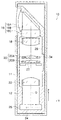
以下、添付図面に従って本発明に係る像ぶれ補正装置の好ましい実施の形態を説明する。図1は本発明に係る像ぶれ補正装置が適用されたデジタルカメラ10を示す斜視図である。同図に示すデジタルカメラ10は、ケース11が薄型の矩形状に形成されており、このケース11の正面には、撮影レンズの第1レンズ群16を構成する固定レンズ16A、ストロボの発光部13、及びストロボ用の調光センサ15が配設される。また、ケース11の上面にはシャッターボタン14、電源スイッチ17が配設される。以下、ケース11を正面から見て左右方向をX方向、奥行き(厚さ)方向をY方向、高さ方向をZ方向とする。   Preferred embodiments of an image blur correction device according to the present invention will be described below with reference to the accompanying drawings. FIG. 1 is a perspective view showing a digital camera 10 to which an image blur correction apparatus according to the present invention is applied. In the digital camera 10 shown in the figure, a case 11 is formed in a thin rectangular shape, and a fixed lens 16A constituting a first lens group 16 of a photographing lens and a strobe light emitting unit 13 are formed on the front surface of the case 11. , And a light control sensor 15 for strobe. A shutter button 14 and a power switch 17 are disposed on the upper surface of the case 11. Hereinafter, when viewing the case 11 from the front, the left-right direction is the X direction, the depth (thickness) direction is the Y direction, and the height direction is the Z direction.

図2は、デジタルカメラ10の縦断面図である。同図に示すように、ケース11の内部にはカメラ本体12が設けられ、さらにカメラ本体12の内部には第1レンズ群16、第2レンズ群18、第3レンズ群20、及び第4レンズ群22が設けられる。第1レンズ群16、第2レンズ群18、及び第4レンズ群22は結像光学系を構成しており、第3レンズ群20は結像光学系によって得られる像のぶれを補正する補正光学系を構成している。   FIG. 2 is a longitudinal sectional view of the digital camera 10. As shown in the figure, a camera body 12 is provided inside the case 11, and further, a first lens group 16, a second lens group 18, a third lens group 20, and a fourth lens are provided inside the camera body 12. A group 22 is provided. The first lens group 16, the second lens group 18, and the fourth lens group 22 constitute an imaging optical system, and the third lens group 20 is correction optics that corrects image blur obtained by the imaging optical system. The system is configured.

第1レンズ群16は、ケース11の正面に配置された固定レンズ16Aと、固定レンズ16の内側(奥側)に配置されたプリズム16Bと、プリズム16Bの下方に配置された固定レンズ16Cとによって構成され、固定レンズ16Aを介して得られる観察像の光路をプリズム16Bによって下方に90°屈曲している。   The first lens group 16 includes a fixed lens 16A disposed in front of the case 11, a prism 16B disposed on the inner side (back side) of the fixed lens 16, and a fixed lens 16C disposed below the prism 16B. The optical path of the observation image formed through the fixed lens 16A is bent downward by 90 ° by the prism 16B.

第2レンズ群18、第3レンズ群20、及び第4レンズ群22は、第1レンズ群16の下方、すなわちZ方向の光軸(以下、単に光軸Oという)に沿って配置されている。   The second lens group 18, the third lens group 20, and the fourth lens group 22 are arranged below the first lens group 16, that is, along the optical axis in the Z direction (hereinafter simply referred to as the optical axis O). .

第2レンズ群18及び第4レンズ群22は、光軸Oに沿ってスライド自在に配置されており、不図示の駆動手段によって光軸O方向にスライド移動する。第2レンズ群18をスライドさせることによってズーム操作が行われ、第4レンズ群22をスライドさせることによってフォーカス操作が行われる。   The second lens group 18 and the fourth lens group 22 are slidably disposed along the optical axis O, and are slid and moved in the direction of the optical axis O by a driving unit (not shown). A zoom operation is performed by sliding the second lens group 18, and a focus operation is performed by sliding the fourth lens group 22.

第4レンズ群22の下方の結像位置24には、CCD26が配設される。なお、図2の符号28は、細かな凹凸が繰り返し形成された反射防止面であり、第1レンズ群16の固定レンズ16Aから入射した光が反射することを防止している。符号27はシャッターである。   A CCD 26 is disposed at the imaging position 24 below the fourth lens group 22. Note that reference numeral 28 in FIG. 2 is an antireflection surface in which fine irregularities are repeatedly formed, and prevents light incident from the fixed lens 16A of the first lens group 16 from being reflected. Reference numeral 27 denotes a shutter.

第3レンズ群20は、可動式の補正レンズ20Aと、固定式の補正レンズ20Bとを備え、可動式の補正レンズ20Aを光軸Oに直交する面内で(すなわち、XY平面内で)移動させることによって、像のぶれを補正している。以下、補正レンズ20Aを移動させる像ぶれ補正装置30の構成について説明する。   The third lens group 20 includes a movable correction lens 20A and a fixed correction lens 20B, and moves the movable correction lens 20A in a plane orthogonal to the optical axis O (that is, in the XY plane). Image blurring is corrected. Hereinafter, the configuration of the image blur correction apparatus 30 that moves the correction lens 20A will be described.

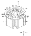
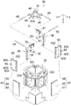
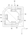
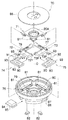
図3は像ぶれ補正装置30を示す斜視図であり、図4はその分解斜視図である。また、図5は、像ぶれ補正装置30の平面図であり、図6は図5の保持枠34を取り除いた平面図である。   FIG. 3 is a perspective view showing the image blur correction device 30, and FIG. 4 is an exploded perspective view thereof. FIG. 5 is a plan view of the image blur correction device 30. FIG. 6 is a plan view in which the holding frame 34 of FIG. 5 is removed.

図4に示すように、像ぶれ補正装置30は主として、略筒状の本体32と、この本体32に移動自在に支持され、補正レンズ20Aを保持する保持枠34と、保持枠34に係合されるXスライダー36及びYスライダー38と、Xスライダー36及びYスライダー38をそれぞれX方向、Y方向に駆動するためのXモータ40及びYモータ42(アクチュエータに相当)とによって構成される。   As shown in FIG. 4, the image blur correction device 30 mainly includes a substantially cylindrical main body 32, a holding frame 34 that is movably supported by the main body 32, and holds the correction lens 20 </ b> A, and engages with the holding frame 34. And an X motor 40 and a Y motor 42 (corresponding to an actuator) for driving the X slider 36 and the Y slider 38 in the X direction and the Y direction, respectively.

図4に示すように保持枠34には、三本のガイドバー44、45、46が取りつけられている。ガイドバー44は、図5に示すように、保持枠34のY方向の側面の略中央位置に、X方向に沿って取りつけられている。ガイドバー45は、保持枠34のX方向の側面の略中央位置に、Y方向に沿って取りつけられている。ガイドバー46は、ガイドバー44、45から最も離れた保持枠34のコーナー部に、対角線方向に沿って取りつけられている。   As shown in FIG. 4, three guide bars 44, 45, 46 are attached to the holding frame 34. As shown in FIG. 5, the guide bar 44 is attached along the X direction at a substantially central position of the side surface of the holding frame 34 in the Y direction. The guide bar 45 is attached along the Y direction at a substantially central position of the side surface of the holding frame 34 in the X direction. The guide bar 46 is attached to the corner portion of the holding frame 34 farthest from the guide bars 44 and 45 along the diagonal direction.

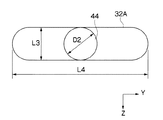
各ガイドバー44〜46はそれぞれ、本体32の溝32A〜32Cに差し込まれている。図8に示すように、溝32Aは、光軸O方向(Z方向)の寸法L3がガイドバー44の直径D2と略同寸法で形成されるとともに、光軸Oに直交する方向(Y方向)の寸法L4がガイドバー44の直径D2よりも大きく形成されている。したがって、ガイドバー44は、溝32Aに対して、光軸O方向に隙間がない状態で係合され、且つ、光軸Oに直交する方向に移動自在に支持される。   The guide bars 44 to 46 are inserted into the grooves 32A to 32C of the main body 32, respectively. As shown in FIG. 8, the groove 32A is formed such that a dimension L3 in the optical axis O direction (Z direction) is substantially the same as the diameter D2 of the guide bar 44, and a direction orthogonal to the optical axis O (Y direction). The dimension L4 is larger than the diameter D2 of the guide bar 44. Therefore, the guide bar 44 is engaged with the groove 32 </ b> A in a state where there is no gap in the optical axis O direction, and is supported so as to be movable in a direction orthogonal to the optical axis O.

同様に、図5の溝32Bは、光軸O方向の寸法がガイドバー45の直径と略同寸法で形成され、且つ、光軸Oに直交する方向の寸法がガイドバー45の直径よりも大きく形成されている。また、溝32Cは、光軸O方向の寸法がガイドバー46の直径と略同寸法で形成され、且つ、光軸Oに直交する方向の寸法がガイドバー46の直径よりも大きく形成されている。したがって、ガイドバー45、46は、溝32B、32Cに対して、光軸O方向に隙間がない状態で係合され、且つ、光軸Oに直交する方向に移動自在に支持される。これにより、保持枠34は、光軸O方向にガタのない状態で、且つ、光軸Oに直交する方向に移動自在に支持される。   Similarly, the groove 32B in FIG. 5 is formed so that the dimension in the direction of the optical axis O is substantially the same as the diameter of the guide bar 45, and the dimension in the direction orthogonal to the optical axis O is larger than the diameter of the guide bar 45. Is formed. Further, the groove 32C is formed so that the dimension in the optical axis O direction is substantially the same as the diameter of the guide bar 46, and the dimension in the direction orthogonal to the optical axis O is larger than the diameter of the guide bar 46. . Therefore, the guide bars 45 and 46 are engaged with the grooves 32B and 32C in a state where there is no gap in the optical axis O direction, and are supported so as to be movable in a direction orthogonal to the optical axis O. As a result, the holding frame 34 is supported in a state free from backlash in the direction of the optical axis O and movably in a direction perpendicular to the optical axis O.

また、保持枠34には、ガイドバー44が取り付けられた側面と反対側の側面に、可動ガイド軸48がY方向に沿って取り付けられている。さらに、保持枠34には、ガイドバー45が取りつけられた側面と反対側の側面に、可動ガイド軸49がX方向に沿って取り付けられている。これらの可動ガイド軸48、49にはそれぞれ、Xスライダー36、Yスライダー38がスライド自在に係合されている。   A movable guide shaft 48 is attached to the holding frame 34 along the Y direction on the side surface opposite to the side surface on which the guide bar 44 is attached. Furthermore, a movable guide shaft 49 is attached to the holding frame 34 along the X direction on the side surface opposite to the side surface to which the guide bar 45 is attached. An X slider 36 and a Y slider 38 are slidably engaged with these movable guide shafts 48 and 49, respectively.

図6、図7に示すように、Xスライダー36とYスライダー38は、平面対称となる形状で形成されている。すなわち、図6に示すように、Xスライダー36は平面図において略L状に形成されており、Yスライダー38は、二点鎖線で示す対称面に対してXスライダー36の平面対称形状となるように、逆L状に形成される。   As shown in FIGS. 6 and 7, the X slider 36 and the Y slider 38 are formed in a shape that is plane symmetric. That is, as shown in FIG. 6, the X-slider 36 is formed in a substantially L shape in the plan view, and the Y-slider 38 has a plane-symmetric shape of the X-slider 36 with respect to the symmetry plane indicated by the two-dot chain line. In addition, it is formed in an inverted L shape.

Xスライダー36には、前述した可動ガイド軸48(図5参照)が挿通されるガイド孔50、50が形成されている。Xスライダー36は、このガイド孔50、50に可動ガイド軸48が挿通されることによって、保持枠34に対してY方向にスライド自在に係合されている。   The X slider 36 is formed with guide holes 50 and 50 through which the above-described movable guide shaft 48 (see FIG. 5) is inserted. The X slider 36 is slidably engaged with the holding frame 34 in the Y direction by inserting the movable guide shaft 48 through the guide holes 50 and 50.

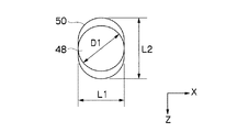
図7、図9に示すように、各ガイド孔50は、X方向よりもZ方向に長い長円状に形成されている。具体的には、ガイド孔50のX方向の寸法L1は、可動ガイド軸48の外径寸法D1と略同寸法で形成されており、ガイド孔50のZ方向の寸法L2は、可動ガイド軸48の外径寸法D1よりも大きく形成されている。したがって、可動ガイド軸48をガイド孔50に挿通させると、X方向に隙間がない状態で可動ガイド軸48とガイド孔50とが係合される。よって、Xスライダー36をX方向に移動させた際、可動ガイド軸48を介して保持枠34をX方向に精度良く移動させることができる。一方で、Z方向には隙間があるので、可動ガイド軸48をガイド孔50に容易に挿通させることができ、組立性が良い。   As shown in FIGS. 7 and 9, each guide hole 50 is formed in an oval shape that is longer in the Z direction than in the X direction. Specifically, the dimension L1 in the X direction of the guide hole 50 is formed to be approximately the same as the outer diameter dimension D1 of the movable guide shaft 48, and the dimension L2 in the Z direction of the guide hole 50 is the movable guide shaft 48. Is formed larger than the outer diameter D1. Therefore, when the movable guide shaft 48 is inserted into the guide hole 50, the movable guide shaft 48 and the guide hole 50 are engaged with each other with no gap in the X direction. Therefore, when the X slider 36 is moved in the X direction, the holding frame 34 can be accurately moved in the X direction via the movable guide shaft 48. On the other hand, since there is a gap in the Z direction, the movable guide shaft 48 can be easily inserted into the guide hole 50, and the assemblability is good.

図7に示すように、Xスライダー36には、貫通孔52がX方向に形成されている。この貫通孔52には、図6に示す固定ガイド軸54が挿通される。固定ガイド軸54は、X方向に沿って配置され、その両端部が本体32に固定される。これにより、Xスライダー36が本体32にX方向にスライド自在に支持される。なお、貫通孔52の断面形状は特に限定するものではないが、円形でもよいし、ガイド孔50のようにZ方向に長い長円状に形成してもよい。   As shown in FIG. 7, the X slider 36 has a through hole 52 formed in the X direction. A fixed guide shaft 54 shown in FIG. 6 is inserted through the through hole 52. The fixed guide shaft 54 is disposed along the X direction, and both ends thereof are fixed to the main body 32. Accordingly, the X slider 36 is supported by the main body 32 so as to be slidable in the X direction. The cross-sectional shape of the through hole 52 is not particularly limited, but may be circular or may be formed in an oval shape that is long in the Z direction like the guide hole 50.

図4に示すように、Xスライダー36には、基板60が光軸Oと平行になるように取り付けられる。基板60には、Xモータ40を構成するコイル58がプリントされている。コイル58は、図10(A)、図10(B)に示すように、Z方向に長い長円状に形成される。また、コイル58は複数層に重ねてプリントされており、その端子は基板60の両面に設けられている。すなわち、図10(A)に示すように基板60の表面60Aには端子62、62が設けられ、図10(B)に示すように基板60の裏面60Bには端子63、63が設けられる。したがって、端子62、62と端子63、63の一方を導線に接続すれば、コイル58に電流を流すことができる。Xスライダー36に装着される基板60は、内側の端子63、63に導線が接続される。   As shown in FIG. 4, the substrate 60 is attached to the X slider 36 so as to be parallel to the optical axis O. A coil 58 constituting the X motor 40 is printed on the substrate 60. As shown in FIGS. 10A and 10B, the coil 58 is formed in an oval shape that is long in the Z direction. The coil 58 is printed in a plurality of layers, and its terminals are provided on both surfaces of the substrate 60. That is, terminals 62 and 62 are provided on the front surface 60A of the substrate 60 as shown in FIG. 10A, and terminals 63 and 63 are provided on the back surface 60B of the substrate 60 as shown in FIG. 10B. Therefore, if one of the terminals 62 and 62 and the terminals 63 and 63 is connected to a conducting wire, a current can be passed through the coil 58. The substrate 60 to be mounted on the X slider 36 has conductors connected to the inner terminals 63 and 63.

基板60には、係合突起60C、係合孔60D、60Dが形成されている。この係合突起60C、係合孔60D、60Dをそれぞれ、図4のXスライダー36の係合溝(不図示)、係合ピン56、56に係合することによって、基板60がXスライダー36に取り付けられる。   The substrate 60 is formed with engagement protrusions 60C and engagement holes 60D and 60D. By engaging the engagement protrusion 60C and the engagement holes 60D and 60D with the engagement groove (not shown) of the X slider 36 and the engagement pins 56 and 56 of FIG. It is attached.

Xモータ40は、前述したコイル58と、本体32に取りつけられた板状のマグネット64及びヨーク66で構成される。マグネット64及びヨーク66は、コイル58を挟んで対向して配置されており、本体32に固定されている。マグネット64は、コイル58の位置で、磁力線がY方向に形成されるようにN極とS極が配置されており、ヨーク66は、その磁力線が強くなるように構成される。このように構成されたXモータ40は、コイル58に通電することによって、コイル58を保持したXスライダー36がX方向に移動される。したがって、Xスライダー36に可動ガイド軸48を介して係合した保持枠34をX方向に駆動することができる。   The X motor 40 includes the coil 58 described above, a plate-like magnet 64 and a yoke 66 attached to the main body 32. The magnet 64 and the yoke 66 are disposed to face each other with the coil 58 interposed therebetween, and are fixed to the main body 32. The magnet 64 has N and S poles arranged so that the magnetic lines of force are formed in the Y direction at the position of the coil 58, and the yoke 66 is configured so that the magnetic lines of force are strong. In the X motor 40 configured as described above, when the coil 58 is energized, the X slider 36 holding the coil 58 is moved in the X direction. Therefore, the holding frame 34 engaged with the X slider 36 via the movable guide shaft 48 can be driven in the X direction.

一方、Yスライダー38には、前述した可動ガイド軸49が挿通されるガイド孔51、51が形成されている。Yスライダー38は、このガイド孔51、51に可動ガイド軸49が挿通されることによって、保持枠34に対してX方向にスライド自在に係合されている。   On the other hand, the Y slider 38 is formed with guide holes 51 and 51 through which the above-described movable guide shaft 49 is inserted. The Y slider 38 is slidably engaged with the holding frame 34 in the X direction by inserting the movable guide shaft 49 through the guide holes 51 and 51.

各ガイド孔51は、図8に示したガイド孔50と同様に、Z方向に長い長円状に形成されている。具体的には、ガイド孔51のY方向の寸法が可動ガイド軸49の外径と略同寸法で形成されており、ガイド孔51のZ方向の寸法が可動ガイド軸49の外径よりも大きく形成されている。したがって、可動ガイド軸49をガイド孔51に挿通させると、Y方向に隙間がない状態で、可動ガイド軸49とガイド孔51とが係合される。よって、Yスライダー38をY方向に移動させた際、可動ガイド軸49を介して保持枠34をY方向に精度良く移動させることができる。一方で、Z方向に隙間があるので、可動ガイド軸49をガイド孔51に容易に挿通させることができ、組立性が良い。   Each guide hole 51 is formed in an oval shape that is long in the Z direction, like the guide hole 50 shown in FIG. Specifically, the dimension of the guide hole 51 in the Y direction is substantially the same as the outer diameter of the movable guide shaft 49, and the dimension of the guide hole 51 in the Z direction is larger than the outer diameter of the movable guide shaft 49. Is formed. Therefore, when the movable guide shaft 49 is inserted through the guide hole 51, the movable guide shaft 49 and the guide hole 51 are engaged with each other with no gap in the Y direction. Therefore, when the Y slider 38 is moved in the Y direction, the holding frame 34 can be accurately moved in the Y direction via the movable guide shaft 49. On the other hand, since there is a gap in the Z direction, the movable guide shaft 49 can be easily inserted into the guide hole 51, and the assemblability is good.

また、Yスライダー38には、貫通孔53がY方向に形成されており、この貫通孔53に固定ガイド軸55が挿通される。固定ガイド軸55は、Y方向に沿って配置され、その両端部が本体32に固定される。これにより、Yスライダー38が本体32にY方向にスライド自在に支持される。なお、貫通孔53の断面形状は特に限定するものではないが、円形でもよいし、ガイド孔51のようにZ方向に長い長円状に形成してもよい。   A through hole 53 is formed in the Y slider 38 in the Y direction, and the fixed guide shaft 55 is inserted into the through hole 53. The fixed guide shaft 55 is disposed along the Y direction, and both ends thereof are fixed to the main body 32. Thereby, the Y slider 38 is supported by the main body 32 so as to be slidable in the Y direction. The cross-sectional shape of the through hole 53 is not particularly limited, but may be circular or may be formed in an oval shape that is long in the Z direction like the guide hole 51.

Yスライダー38には、基板60が光軸Oと平行になるように取りつけられている。この基板60は、前述したXスライダー36に取りつけられた基板60と同じものであり、基板60には、係合突起60C、係合孔60D、60Dが形成されている。この係合突起60C、係合孔60D、60Dを、Yスライダー38の係合溝(不図示)、係合ピン57、57に係合することによって基板60がYスライダー38に取りつけられる。その際、基板60は、Xスライダー36とYスライダー38とで、異なる姿勢で取りつけられる。すなわち、Xスライダー36には、基板60の表面60Aが外側を向く姿勢で取りつけられ(図10(A)参照)、Yスライダー38には、基板60の裏面60Bが外側を向く姿勢(図10(B)参照)で取りつけられる。Yスライダー38に取りつけられた基板60は、内側の端子62、62に導線が接続され、この導線を介して電流が供給される。   A substrate 60 is attached to the Y slider 38 so as to be parallel to the optical axis O. The substrate 60 is the same as the substrate 60 attached to the X slider 36 described above, and the substrate 60 is formed with engagement protrusions 60C and engagement holes 60D and 60D. The substrate 60 is attached to the Y slider 38 by engaging the engagement protrusions 60 </ b> C and the engagement holes 60 </ b> D and 60 </ b> D with engagement grooves (not shown) of the Y slider 38 and engagement pins 57 and 57. At that time, the substrate 60 is mounted in different postures by the X slider 36 and the Y slider 38. That is, the front surface 60A of the substrate 60 is attached to the X slider 36 in a posture that faces outward (see FIG. 10A), and the rear surface 60B of the substrate 60 faces to the outer side in the Y slider 38 (see FIG. (See B)). The substrate 60 attached to the Y slider 38 is connected to the inner terminals 62 and 62 with conductive wires, and current is supplied through the conductive wires.

Yモータ42は、前述したコイル58と、本体32に取りつけられた板状のマグネット65及びヨーク67で構成される。マグネット65及びヨーク67は、コイル58を挟んで対向して配置されており、本体32に固定されている。マグネット65は、コイル58の位置で、磁力線がX方向に形成されるようにN極とS極が配置されており、ヨーク67は、その磁力線が強くなるように構成されている。このように構成されたYモータ42は、コイル58に通電することによって、コイル58を保持したYスライダー38がY方向に移動される。したがって、Yスライダー38に可動ガイド軸49を介して係合した保持枠34をY方向に駆動することができる。   The Y motor 42 includes the coil 58 described above, a plate-shaped magnet 65 attached to the main body 32, and a yoke 67. The magnet 65 and the yoke 67 are arranged to face each other with the coil 58 interposed therebetween, and are fixed to the main body 32. The magnet 65 has an N pole and an S pole arranged so that the magnetic lines of force are formed in the X direction at the position of the coil 58, and the yoke 67 is configured so that the magnetic lines of force are strong. In the Y motor 42 configured as described above, when the coil 58 is energized, the Y slider 38 holding the coil 58 is moved in the Y direction. Therefore, the holding frame 34 engaged with the Y slider 38 via the movable guide shaft 49 can be driven in the Y direction.

上述したXスライダー36、Yスライダー38、Xモータ40、及びYモータ42は、保持枠34の被写体側にまとめて配設されるとともに、図3に示すように、略筒状の本体32内に組み込まれ、ユニット化されている。したがって、像ぶれ補正装置30を小型化することができ、且つ、カメラ10に容易に組み込むことができる。   The X slider 36, the Y slider 38, the X motor 40, and the Y motor 42 described above are collectively disposed on the subject side of the holding frame 34, and as shown in FIG. Built and unitized. Therefore, the image blur correction device 30 can be reduced in size and can be easily incorporated into the camera 10.

なお、像ぶれ補正装置30には、Xスライダー36、Yスライダー38の位置を検出する位置検出センサ(不図示)を設けるとよい。位置検出センサの種類は特に限定するものではないが、たとえばXスライダー36、Yスライダー38に取りつけられたホール素子と、このホール素子に対向して配置され、且つ、本体32に固定されたマグネットによって構成するとよい。これにより、Xスライダー36、Yスライダー38の位置、すなわち、保持枠34の位置を制御することができる。   The image blur correction device 30 may be provided with a position detection sensor (not shown) that detects the positions of the X slider 36 and the Y slider 38. The type of the position detection sensor is not particularly limited. For example, a hall element attached to the X slider 36 and the Y slider 38 and a magnet disposed opposite to the hall element and fixed to the main body 32 are used. Configure. Thereby, the position of the X slider 36 and the Y slider 38, that is, the position of the holding frame 34 can be controlled.

また、カメラ10のカメラ本体12に、振動検出センサ(不図示)を設け、このセンサの検出値に応じてXモータ40、Yモータ42を駆動制御するとよい。   Further, a vibration detection sensor (not shown) may be provided in the camera body 12 of the camera 10 and the X motor 40 and the Y motor 42 may be driven and controlled according to the detection value of this sensor.

次に上記の如く構成された像ぶれ補正装置30の作用について説明する。   Next, the operation of the image blur correction device 30 configured as described above will be described.

カメラ10の振動をセンサ(不図示)で検出した際、その検出した振動の方向に応じて、Xモータ40またはYモータ42若しくは両方のモータ40、42が駆動される。Xモータ40が駆動されると、コイル58に通電され、コイル58を保持したXスライダー36がX方向に移動する。したがって、Xスライダー36に可動ガイド軸48を介して係合した保持枠34がX方向に移動し、補正レンズ20AがX方向に移動する。その際、Yスライダー38は、保持枠34に対してX方向にスライド自在に係合しているので、移動しない。したがって、Xモータ40を駆動した際に、Yスライダー38やYモータ42を移動させることなくXスライダー36のみを独立して移動させることができ、保持枠34を迅速に移動させることができる。   When the vibration of the camera 10 is detected by a sensor (not shown), the X motor 40 or the Y motor 42 or both the motors 40 and 42 are driven according to the detected vibration direction. When the X motor 40 is driven, the coil 58 is energized, and the X slider 36 holding the coil 58 moves in the X direction. Accordingly, the holding frame 34 engaged with the X slider 36 via the movable guide shaft 48 moves in the X direction, and the correction lens 20A moves in the X direction. At that time, the Y slider 38 is slidably engaged with the holding frame 34 in the X direction, and therefore does not move. Therefore, when the X motor 40 is driven, only the X slider 36 can be moved independently without moving the Y slider 38 and the Y motor 42, and the holding frame 34 can be moved quickly.

また、Xモータ40を駆動した際、可動ガイド軸48とXスライダー36のガイド孔50がX方向に隙間のない状態で係合しているので、保持枠34をX方向に高精度で移動させることができる。このように、本実施の形態によれば、Xモータ40を駆動した際に保持枠34をX方向に高精度で迅速に移動させることができる。   Further, when the X motor 40 is driven, the movable guide shaft 48 and the guide hole 50 of the X slider 36 are engaged with no gap in the X direction, so that the holding frame 34 is moved in the X direction with high accuracy. be able to. Thus, according to the present embodiment, when the X motor 40 is driven, the holding frame 34 can be quickly moved with high accuracy in the X direction.

同様に、Yモータ42を駆動した際には、コイル58を保持したYスライダー38がY方向に移動する。したがって、Yスライダー38に可動ガイド軸49を介して係合した保持枠34がY方向に移動し、補正レンズ20AがY方向に移動する。その際、Xスライダー36は、保持枠34に対してY方向にスライド自在に係合しているので、移動しない。したがって、Yモータ42を駆動した際に、Xスライダー36やXモータ40を移動させることなくYスライダー38のみを独立して移動させることができ、保持枠34を迅速に移動させることができる。   Similarly, when the Y motor 42 is driven, the Y slider 38 holding the coil 58 moves in the Y direction. Therefore, the holding frame 34 engaged with the Y slider 38 via the movable guide shaft 49 moves in the Y direction, and the correction lens 20A moves in the Y direction. At that time, the X slider 36 is slidably engaged with the holding frame 34 in the Y direction, and therefore does not move. Therefore, when the Y motor 42 is driven, only the Y slider 38 can be moved independently without moving the X slider 36 and the X motor 40, and the holding frame 34 can be moved quickly.

また、Yモータ42を駆動した際、可動ガイド軸49とYスライダー38のガイド孔51がY方向に隙間のない状態で係合しているので、保持枠34をY方向に高精度で移動させることができる。このように本実施の形態によれば、Yモータ42を駆動した際に保持枠34をY方向に高精度で迅速に移動させることができる。   Further, when the Y motor 42 is driven, the movable guide shaft 49 and the guide hole 51 of the Y slider 38 are engaged with no gap in the Y direction, so that the holding frame 34 is moved in the Y direction with high accuracy. be able to. Thus, according to the present embodiment, when the Y motor 42 is driven, the holding frame 34 can be quickly moved with high accuracy in the Y direction.

ところで、本実施の形態の像ぶれ補正装置30は、上述したように、Xスライダー36とYスライダー38とが平面対称形状で形成されるとともに、基板60の表面60Aに端子62、62が設けられ、裏面60Bに端子63、63が設けられている。したがって、Xモータ40とYモータ42とで同じ構成の基板60を用いることができ、Xスライダー36とYスライダー38の両方に、基板60、60を装着して使用することができる。   Incidentally, in the image blur correction device 30 of the present embodiment, as described above, the X slider 36 and the Y slider 38 are formed in a plane-symmetric shape, and terminals 62 and 62 are provided on the surface 60A of the substrate 60. Terminals 63 and 63 are provided on the back surface 60B. Therefore, the substrate 60 having the same configuration can be used for the X motor 40 and the Y motor 42, and the substrates 60 and 60 can be attached to both the X slider 36 and the Y slider 38 for use.

このように本実施の形態によれば、同じ構成の基板60を用いるようにしたので、構成部品の種類を減らすことができる。特に、本実施の形態では、単価の高い基板60を共通化したので、コストを大幅に削減することができる。   As described above, according to the present embodiment, since the substrate 60 having the same configuration is used, the types of components can be reduced. In particular, in this embodiment, since the substrate 60 having a high unit price is shared, the cost can be greatly reduced.

また、本実施の形態によれば、Xスライダー36とYスライダー38とが平面対称形状で形成されている。したがって、保持枠34をX方向に移動する機構と、保持枠34をY方向に移動する機構とが平面対称形状になっている。これにより、保持枠34のX方向への移動する際と、Y方向への移動する際とで、移動特性が等しくなる。したがって、保持枠34の移動方向によって移動速度にバラツキが生じることがなく、保持枠34を常に高精度で移動させることができる。   Further, according to the present embodiment, the X slider 36 and the Y slider 38 are formed in a plane symmetrical shape. Therefore, the mechanism for moving the holding frame 34 in the X direction and the mechanism for moving the holding frame 34 in the Y direction have a plane-symmetric shape. Thereby, when the holding frame 34 moves in the X direction and when it moves in the Y direction, the movement characteristics are equal. Therefore, the moving speed does not vary depending on the moving direction of the holding frame 34, and the holding frame 34 can always be moved with high accuracy.

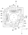
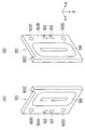
図11は、図4と異なる構成の像ぶれ補正装置70を示す分解斜視図である。同図において、図4の像ぶれ補正装置30と同様の構成、作用を有する部材については同じ符号を付して、その説明を省略する。   FIG. 11 is an exploded perspective view showing an image blur correction device 70 having a configuration different from that in FIG. In the figure, members having the same configuration and function as those of the image blur correction device 30 in FIG. 4 are denoted by the same reference numerals, and description thereof is omitted.

図11に示すように、像ぶれ補正装置70は主として、補正レンズ20Aを保持する保持枠71と、この保持枠71を支持する第1、第2のスライダー72、73と、この第1、第2のスライダー72、73を移動させる第1、第2のボイスコイルモータ(以下、第1モータ、第2モータという)74、75と、鏡胴76とで構成される。   As shown in FIG. 11, the image blur correction apparatus 70 mainly includes a holding frame 71 that holds the correction lens 20 </ b> A, first and second sliders 72 and 73 that support the holding frame 71, and the first and first sliders. The first and second voice coil motors (hereinafter referred to as the first motor and the second motor) 74 and 75 for moving the two sliders 72 and 73, and the lens barrel 76.

保持枠71は、その外形が略矩形状に形成されている。また保持枠71は、光軸Oに直交する面内において、直交する二方向に移動自在に支持されている。以下、この二方向をP(ピッチ)方向、Y(ヨー)方向とする。保持枠71の側面には、P方向に配置されたPガイド棒77と、Y方向に配置されたYガイド棒78が取り付けられる。   The outer shape of the holding frame 71 is formed in a substantially rectangular shape. The holding frame 71 is supported so as to be movable in two orthogonal directions within a plane orthogonal to the optical axis O. Hereinafter, these two directions are referred to as a P (pitch) direction and a Y (yaw) direction. A P guide rod 77 arranged in the P direction and a Y guide rod 78 arranged in the Y direction are attached to the side surface of the holding frame 71.

一方、鏡胴76には、P方向に配置されたPガイド棒79と、Y方向に配置されたYガイド棒80とが保持されている。Pガイド棒77、Yガイド棒78はそれぞれ、光軸Oを挟んでPガイド棒79、Yガイド棒80の反対側に配置される。   On the other hand, the lens barrel 76 holds a P guide rod 79 arranged in the P direction and a Y guide rod 80 arranged in the Y direction. The P guide rod 77 and the Y guide rod 78 are respectively arranged on the opposite sides of the P guide rod 79 and the Y guide rod 80 with the optical axis O interposed therebetween.

第1スライダー72は、略L状に形成されており、P方向の二つのガイド孔72P(一つのみ図示)が形成される。このガイド孔72Pに前述のPガイド棒79を挿通させることによって、第1スライダー72が鏡胴76に対してP方向にスライド自在に支持される。   The first slider 72 is formed in an approximately L shape, and two guide holes 72P (only one is shown) in the P direction are formed. By inserting the aforementioned P guide rod 79 into the guide hole 72P, the first slider 72 is supported slidably in the P direction with respect to the lens barrel 76.

また、第1スライダー72には、Y方向の二つのガイド孔72Y、72Yが形成される。このガイド孔72Y、72Yに前述のYガイド棒78を挿通させることによって、第1スライダー72が保持枠71に対してY方向に移動自在に支持される。   The first slider 72 has two guide holes 72Y and 72Y in the Y direction. By inserting the Y guide rod 78 into the guide holes 72Y and 72Y, the first slider 72 is supported so as to be movable in the Y direction with respect to the holding frame 71.

第2スライダー73は、第1スライダー72に対して平面対称となる形状に形成されており、略逆L状に形成されている。この第2スライダー73には、Y方向の二つのガイド孔73Y(一つのみ図示)が形成される。このガイド孔73Yに前述のガイド棒80を挿通させることによって、第2スライダー73が鏡胴76に対してY方向にスライド自在に支持される。   The second slider 73 is formed in a shape that is plane-symmetric with respect to the first slider 72, and is formed in a substantially inverted L shape. The second slider 73 is formed with two guide holes 73Y (only one is shown) in the Y direction. By inserting the above-described guide rod 80 through the guide hole 73Y, the second slider 73 is supported slidably in the Y direction with respect to the lens barrel 76.

また、第2スライダー73には、P方向の二つのガイド孔73P、73Pが形成される。このガイド孔73P、73Pに前述のPガイド棒77を挿通させることによって、第2スライダー73が保持枠71に対してP方向に移動自在に支持される。   The second slider 73 is formed with two guide holes 73P and 73P in the P direction. By inserting the aforementioned P guide rod 77 into the guide holes 73P and 73P, the second slider 73 is supported so as to be movable in the P direction with respect to the holding frame 71.

なお、図11の符号81、81…は、ゴムやウレタン樹脂等の衝撃吸収材から成る緩衝部材であり、筒状に形成されてPガイド棒77、79やYガイド棒78、80に挿通された状態で取りつけられる。この緩衝部材81、81…によって、第1スライダー72、第2スライダー73が、保持枠71や鏡胴76に衝突して破損することを防止することができる。   11 are shock absorbing members made of an impact absorbing material such as rubber or urethane resin, and are formed in a cylindrical shape and inserted into the P guide rods 77 and 79 and the Y guide rods 78 and 80. It can be installed in the state. The buffer members 81, 81... Can prevent the first slider 72 and the second slider 73 from colliding with the holding frame 71 and the lens barrel 76 and being damaged.

また、図11の符号82は、位置検出センサを構成するマグネットであり、鏡胴76に取りつけられている。このマグネット82に対向して、不図示のホール素子が第1スライダー72、第2スライダー73に取りつけられる。この位置検出センサの測定値に基づいて、第1モータ74、第2モータ75が駆動制御される。   Further, reference numeral 82 in FIG. 11 denotes a magnet constituting a position detection sensor, which is attached to the lens barrel 76. A hall element (not shown) is attached to the first slider 72 and the second slider 73 so as to face the magnet 82. Based on the measured value of the position detection sensor, the first motor 74 and the second motor 75 are driven and controlled.

第1モータ74は主として、基板83、マグネット84、ヨーク85、及び、円盤型ヨーク86によって構成される。同様に、第2モータ75は、基板83、マグネット87、ヨーク88、及び、円盤型ヨーク86によって構成される。円盤型ヨーク86は、第1モータ74と第2モータ75とで兼用される。また、基板83は、後述するように、第1モータ74と第2モータ75とで共通のものが使用される。   The first motor 74 is mainly composed of a substrate 83, a magnet 84, a yoke 85, and a disk type yoke 86. Similarly, the second motor 75 includes a substrate 83, a magnet 87, a yoke 88, and a disk type yoke 86. The disk-type yoke 86 is shared by the first motor 74 and the second motor 75. Further, as described later, the substrate 83 is common to the first motor 74 and the second motor 75.

マグネット84、87はそれぞれヨーク85、88の上に固定されており、鏡胴76に取りつけられることによって、基板83、83に対向するように配置される。一方、円盤型ヨーク86は、金属板によってリング状に形成されており、鏡胴76に取りつけられることによって基板83、83に対向するようにして配置される。   The magnets 84 and 87 are respectively fixed on the yokes 85 and 88 and are disposed so as to face the substrates 83 and 83 by being attached to the lens barrel 76. On the other hand, the disk-shaped yoke 86 is formed in a ring shape by a metal plate, and is disposed so as to face the substrates 83 and 83 by being attached to the lens barrel 76.

基板83には、コイル90がプリントされており、このコイル90はY方向に長い長円状に形成されるとともに複数層に重ねてプリントされる。コイル90の端子は基板の両面に設けられている。すなわち、基板83の一方の面には、端子91、91が設けられ、基板83のもう一方の面には端子92、92が設けられる。また、基板83には、取付孔93、93が形成されており、この取付孔93、93に、第1スライダー72または第2スライダー73に設けた係合突起(不図示)を挿入することによって、第1スライダー72または第2スライダー73に基板83が取りつけられる。   A coil 90 is printed on the substrate 83. The coil 90 is formed in an ellipse shape that is long in the Y direction, and is printed in multiple layers. The terminals of the coil 90 are provided on both sides of the substrate. That is, terminals 91 and 91 are provided on one surface of the substrate 83, and terminals 92 and 92 are provided on the other surface of the substrate 83. In addition, mounting holes 93 and 93 are formed in the substrate 83, and an engaging protrusion (not shown) provided on the first slider 72 or the second slider 73 is inserted into the mounting holes 93 and 93. The substrate 83 is attached to the first slider 72 or the second slider 73.

第1モータ74の基板83は、端子91、91側の面が当接するように第1スライダー72に取りつけられ、端子92、92に不図示の導線が接続される。第2モータ75の基板83は、端子92、92側の面が当接するように第2スライダー74に取りつけられ、端子91、91に不図示の導線が接続される。   The board 83 of the first motor 74 is attached to the first slider 72 so that the surfaces of the terminals 91 and 91 are in contact with each other, and a conductor (not shown) is connected to the terminals 92 and 92. The board 83 of the second motor 75 is attached to the second slider 74 so that the surfaces of the terminals 92 and 92 are in contact with each other, and a conductor (not shown) is connected to the terminals 91 and 91.

次に上記の如く構成された像ぶれ補正装置70の作用について説明する。   Next, the operation of the image blur correction device 70 configured as described above will be described.

第1モータ74を駆動すると、第1モータ74の基板83を支持する第1スライダー72に駆動力が伝わり、第1スライダー72がP方向に移動する。これにより、第1スライダー72にYガイド棒78を介して取り付けられた保持枠71がP方向に移動し、補正レンズ20AがP方向に移動する。その際、第2スライダー73は保持枠71に対してP方向にスライド自在に支持されているので、第2スライダー73が移動することがない。すなわち、第1モータ74を駆動すると、第2スライダー73、第2モータ75は移動せずに、第1スライダー72のみが独立して移動する。   When the first motor 74 is driven, the driving force is transmitted to the first slider 72 that supports the substrate 83 of the first motor 74, and the first slider 72 moves in the P direction. As a result, the holding frame 71 attached to the first slider 72 via the Y guide rod 78 moves in the P direction, and the correction lens 20A moves in the P direction. At this time, since the second slider 73 is supported so as to be slidable in the P direction with respect to the holding frame 71, the second slider 73 does not move. That is, when the first motor 74 is driven, the second slider 73 and the second motor 75 do not move, and only the first slider 72 moves independently.

一方、第2モータ75を駆動すると、第2モータ75の基板83を支持する第2スライダー73に駆動力が伝わり、第2スライダー75がY方向に移動する。これにより、第2スライダー73にPガイド棒77を介して取り付けられた保持枠71がY方向に移動し、補正レンズ20AがY方向に移動する。その際、第1スライダー72は保持枠71に対してY方向にスライド自在に支持されているので、第1スライダー72が移動することがない。すなわち、第2モータ75を駆動すると、第1スライダー72、第1モータ74は移動せずに、第2スライダーのみが独立して移動する。   On the other hand, when the second motor 75 is driven, the driving force is transmitted to the second slider 73 that supports the substrate 83 of the second motor 75, and the second slider 75 moves in the Y direction. As a result, the holding frame 71 attached to the second slider 73 via the P guide rod 77 moves in the Y direction, and the correction lens 20A moves in the Y direction. At this time, since the first slider 72 is supported so as to be slidable in the Y direction with respect to the holding frame 71, the first slider 72 does not move. That is, when the second motor 75 is driven, the first slider 72 and the first motor 74 do not move, but only the second slider moves independently.

このように本実施の形態によれば、第1モータ74、第2モータ75をそれぞれ駆動することによって、第1スライダー72、第2スライダー73が独立して移動するので、少ない動力で補正レンズ20Aの保持枠71をP方向、Y方向に移動させることができ、且つ、保持枠71を迅速、且つ正確に移動させることができる。   As described above, according to the present embodiment, since the first slider 72 and the second slider 73 move independently by driving the first motor 74 and the second motor 75, respectively, the correction lens 20A with less power. The holding frame 71 can be moved in the P direction and the Y direction, and the holding frame 71 can be moved quickly and accurately.

また、本実施の形態の像ぶれ補正装置70は、第1スライダー72と第2スライダー73とを平面対称形状に形成するとともに、基板83の両面に端子91、91、92、92を設けることによって、第1モータ74と第2モータ75とで、共通の基板83を使用できるように構成している。よって、第1モータ74と第2モータ75とで同じ構成の基板83を用いることができ、構成部品の種類を減らすことができる。特に、本実施の形態では、単価の高い基板83を共通化したので、コストを大幅に削減することができる。   In addition, the image blur correction device 70 according to the present embodiment forms the first slider 72 and the second slider 73 in a plane symmetrical shape, and provides terminals 91, 91, 92, 92 on both surfaces of the substrate 83. The first motor 74 and the second motor 75 are configured so that a common substrate 83 can be used. Therefore, the board | substrate 83 of the same structure can be used with the 1st motor 74 and the 2nd motor 75, and the kind of component can be reduced. In particular, in the present embodiment, since the substrate 83 having a high unit price is shared, the cost can be greatly reduced.

また、本実施の形態によれば、第1スライダー72と第2スライダー73とが平面対称形状で形成されており、保持枠71をP方向に移動する機構とY方向に移動させる機構とが平面対称になっている。したがって、保持枠71のP方向への移動と、Y方向への移動とで移動特性が等しくなり、保持枠71を常に高精度で移動させることができる。   Further, according to the present embodiment, the first slider 72 and the second slider 73 are formed in a plane symmetrical shape, and the mechanism for moving the holding frame 71 in the P direction and the mechanism for moving in the Y direction are planes. It is symmetrical. Therefore, the movement characteristics are equal between the movement of the holding frame 71 in the P direction and the movement in the Y direction, and the holding frame 71 can always be moved with high accuracy.

本発明に係る像ぶれ補正装置が適用されたデジタルカメラを示す斜視図1 is a perspective view showing a digital camera to which an image blur correction apparatus according to the present invention is applied. 図1のデジタルカメラの縦断面図1 is a longitudinal sectional view of the digital camera of FIG. 本発明に係る像ぶれ補正装置を示す斜視図The perspective view which shows the image blurring correction apparatus which concerns on this invention 図3の像ぶれ補正装置の分解斜視図FIG. 3 is an exploded perspective view of the image blur correction device in FIG. 3. 図3の像ぶれ補正装置の平面図FIG. 3 is a plan view of the image blur correction device of FIG. 図5の保持枠を取り除いた像ぶれ補正装置の平面図FIG. 5 is a plan view of the image blur correction apparatus with the holding frame of FIG. 5 removed. XスライダーとYスライダーを示す斜視図Perspective view showing X slider and Y slider 保持枠のガイドの形状を示す模式図Schematic diagram showing the shape of the guide of the holding frame Xスライダーのガイドの形状を示す模式図Schematic diagram showing the shape of the X slider guide コイルを保持した基板を示す斜視図A perspective view showing a substrate holding a coil 別構成の像ぶれ補正装置を示す分解斜視図Exploded perspective view showing an image blur correction device of another configuration

符号の説明Explanation of symbols

10…デジタルカメラ、12…カメラ本体、20A…補正レンズ、30…像ぶれ補正装置、32…本体、34…保持枠、36…Xスライダー、38…Yスライダー、40…Xモータ、42…Yモータ、58…コイル、60…基板、62、63…端子、64、65…マグネット、66、67…ヨーク   DESCRIPTION OF SYMBOLS 10 ... Digital camera, 12 ... Camera body, 20A ... Correction lens, 30 ... Image blur correction apparatus, 32 ... Main body, 34 ... Holding frame, 36 ... X slider, 38 ... Y slider, 40 ... X motor, 42 ... Y motor 58 ... Coil, 60 ... Substrate, 62, 63 ... Terminal, 64, 65 ... Magnet, 66, 67 ... Yoke

Claims (2)

結像光学系によって形成される像のぶれを補正する補正光学系と、
前記補正光学系を保持するとともに、前記結像光学系の光軸に直交する面内で移動自在に支持される保持枠と、
前記光軸に直交し、異なる第1、第2の方向にそれぞれスライド自在に支持されるとともに、前記保持枠に係合される第1、第2のスライダーと、
コイルを支持するとともに前記第1、第2のスライダーに取りつけられる基板を有し、前記コイルに通電することによって前記第1、第2のスライダーをそれぞれ、前記第1、第2の方向に移動させる第1、第2のアクチュエータと、
を備え、
前記基板は、第1、第2のスライダーの両方に適用できるように、前記コイルの接続端子が、表面と裏面の同一対応位置に形成されたことを特徴とする像ぶれ補正装置。
A correction optical system for correcting blurring of an image formed by the imaging optical system;
A holding frame that holds the correction optical system and is movably supported in a plane perpendicular to the optical axis of the imaging optical system;
First and second sliders orthogonal to the optical axis and slidably supported in different first and second directions, respectively, and engaged with the holding frame;
A substrate that supports the coil and is attached to the first and second sliders and moves the first and second sliders in the first and second directions by energizing the coil, respectively. First and second actuators;
With
The image blur correction apparatus according to claim 1, wherein the connection terminal of the coil is formed at the same corresponding position on the front surface and the back surface so that the substrate can be applied to both the first and second sliders.
前記第1、第2のスライダーは対称形状で形成されたことを特徴とする請求項1に記載の像ぶれ補正装置。   2. The image blur correction apparatus according to claim 1, wherein the first and second sliders are formed in a symmetrical shape.
JP2005308900A 2005-10-24 2005-10-24 Image blur correcting apparatus Pending JP2007114709A (en)

Priority Applications (1)

Application Number Priority Date Filing Date Title
JP2005308900A JP2007114709A (en) 2005-10-24 2005-10-24 Image blur correcting apparatus

Applications Claiming Priority (1)

Application Number Priority Date Filing Date Title
JP2005308900A JP2007114709A (en) 2005-10-24 2005-10-24 Image blur correcting apparatus

Publications (1)

Publication Number Publication Date
JP2007114709A true JP2007114709A (en) 2007-05-10

Family

ID=38096913

Family Applications (1)

Application Number Title Priority Date Filing Date
JP2005308900A Pending JP2007114709A (en) 2005-10-24 2005-10-24 Image blur correcting apparatus

Country Status (1)

Country Link
JP (1) JP2007114709A (en)

Similar Documents

Publication Publication Date Title
EP3696587B1 (en) Auto focus and optical image stabilization in a compact folded camera
JP6960983B2 (en) Imaging device with image stabilization function
US8582205B2 (en) Lens barrel and optical apparatus including the same
US7907837B2 (en) Image blur correction apparatus
JP5909877B2 (en) Imaging device
US12126885B2 (en) Camera module with sensor shifting module
JP2012120303A (en) Actuator, and driving device and imaging apparatus including the same
US12407927B2 (en) Sensor shifting module and camera module having the same
US12262114B2 (en) Camera module with sensor shifting module
JP5483988B2 (en) Image blur correction device
JP4899712B2 (en) Lens barrel
JP6376801B2 (en) Image blur correction device, lens barrel, and optical apparatus
US12276811B2 (en) Sensor shifting actuator and camera module including sensor shifting actuator
JP2008096773A (en) Blur correction mechanism and optical device
JP2011039103A5 (en)
JP2006243704A (en) Device for image blur correction and image pickup device
JP2010139821A (en) Lens drive device
JP4823934B2 (en) Image blur correction device, lens barrel, and imaging device
JP2007148023A (en) Image blur correcting device and imaging apparatus using the same
JP2010271513A (en) Optical image stabilizer and optical apparatus
JP5208691B2 (en) Image blur correction device
JP2007114709A (en) Image blur correcting apparatus
JP2007114708A (en) Image blur correcting apparatus
US8165462B2 (en) Shake correction module for photographing apparatus and photographing apparatus including the same
JP2013003524A (en) Image blur correction device and optical equipment using the same