JP2007103232A - Led lighting circuit - Google Patents
Led lighting circuit Download PDFInfo
- Publication number
- JP2007103232A JP2007103232A JP2005293667A JP2005293667A JP2007103232A JP 2007103232 A JP2007103232 A JP 2007103232A JP 2005293667 A JP2005293667 A JP 2005293667A JP 2005293667 A JP2005293667 A JP 2005293667A JP 2007103232 A JP2007103232 A JP 2007103232A
- Authority
- JP
- Japan
- Prior art keywords
- switch
- led
- current
- coil
- limit value
- Prior art date
- Legal status (The legal status is an assumption and is not a legal conclusion. Google has not performed a legal analysis and makes no representation as to the accuracy of the status listed.)
- Granted
Links
Images


Classifications
-
- H—ELECTRICITY
- H05—ELECTRIC TECHNIQUES NOT OTHERWISE PROVIDED FOR
- H05B—ELECTRIC HEATING; ELECTRIC LIGHT SOURCES NOT OTHERWISE PROVIDED FOR; CIRCUIT ARRANGEMENTS FOR ELECTRIC LIGHT SOURCES, IN GENERAL
- H05B45/00—Circuit arrangements for operating light-emitting diodes [LED]
- H05B45/30—Driver circuits
- H05B45/37—Converter circuits
- H05B45/3725—Switched mode power supply [SMPS]
Abstract
Description
本発明は、直流電源からの電流で励磁されエネルギーを蓄積するコイルを有し、直流電源およびコイルの少なくともいずれか一方のエネルギーによりLEDを点灯駆動するLED点灯回路に関する。 The present invention relates to an LED lighting circuit that has a coil that is excited by a current from a DC power source and stores energy, and that drives the LED to be driven by the energy of at least one of the DC power source and the coil.
発光ダイオード(LED)は低抵抗特性であるので、LED点灯回路としては定電圧電源ではなく定電流電源で駆動されることが望ましい。一般に、定電圧電源は一般市販品も多く存在しその回路方式もほぼ確定しているが、定電流電源は測定器を除き一般市販品はほとんど存在しない。特にLED点灯用としての定電流電源は、測定器並みの精度は必要としないので、高価な測定器用の定電流電源を用いることは好ましくない。 Since the light emitting diode (LED) has a low resistance characteristic, the LED lighting circuit is preferably driven by a constant current power supply instead of a constant voltage power supply. In general, many constant-voltage power supplies exist in general commercial products and their circuit systems are almost fixed. However, there are few constant-current power supplies except for measuring instruments. In particular, a constant current power source for lighting an LED does not require the same accuracy as a measuring instrument, and therefore it is not preferable to use an expensive constant current power source for a measuring instrument.
一方、LED点灯制御用として、携帯電話などの表示またはバックライト用としてのLED点灯の電流制御用ICが存在するが、これは3V程度の電池を使用した低電圧小電力の定電流電源であるので、数個のLEDしか点灯することができない。このような電流制御用ICを照明目的で、高電圧および大電力の制御に用いるには、多くの外付け部品を必要としあまり実用的ではない。 On the other hand, there is an LED lighting current control IC for LED lighting control, such as a display for a mobile phone or a backlight, which is a low voltage, low power constant current power source using a battery of about 3V. Therefore, only a few LEDs can be lit. In order to use such a current control IC for the purpose of lighting and control of a high voltage and a high power, many external parts are required and it is not very practical.
そのため、LEDを、照明用として利用する目的で、家庭用AC100Vまたは、自動車のバッテリーなどから、数個〜数百個のLEDを一斉に高効率で、点灯するための定電流電源回路の実用化が必要である。 Therefore, for the purpose of using LEDs for lighting, practical application of constant current power supply circuit for lighting several to several hundred LEDs simultaneously and efficiently from household AC100V or automobile battery etc. is required.
ここで、直流電源にて高効率でLEDを点灯させるものとして、スイッチが閉のときは直流電源からインダクタを励磁しつつインダクタに直列接続されたLEDに直流電源を供給し、スイッチが開のときはインダクタとLEDとの閉回路を形成してインダクタに蓄えられたエネルギーでLEDを点灯するするように形成したものがある(例えば、特許文献1参照)。 Here, it is assumed that the LED is lit with high efficiency by the DC power source. When the switch is closed, the DC power source is supplied to the LED connected in series with the inductor while exciting the inductor from the DC power source, and the switch is opened. In some cases, a closed circuit of an inductor and an LED is formed so that the LED is turned on with energy stored in the inductor (see, for example, Patent Document 1).
また、点灯させるべきLEDに半導体スイッチおよびシャントを直列に接続し、半導体スイッチ3のオンオフによりLEDにパルス状の電流を供給し、一方、LEDへ電流が流れ始めて不完全積分器の出力がヒステリシスコンパレータの上限に達すると、半導体スイッチをオンからオフへ切り換え、不完全積分器の出力がヒステリシスコンパレータの下限まで下がると、半導体スイッチをオフからオンへ切り換えるようにしたものがある(例えば、特許文献2参照)。これにより、LED点灯回路における電力損失を少なくするとともに、LED点灯回路のIC化を可能にしている。
しかし、特許文献1のものでは、スイッチを閉じている時間によってLEDに流れる電流値を制御することになるが、そのためにはスイッチを閉じている時間を調整することが必要となり、制御手段にスイッチのオフ期間を定めるタイマー回路が必要となる。また、LEDに流れる電流値を検出していないので、実際にLEDに流れる電流値をフィードバック制御することができない。
However, in
一方、特許文献2のものではシャントによりLEDに流れる電流を検出し不完全積分回路を介してヒステリシスコンパレータにフィードバックしているが、ヒステリシスコンパレータには半導体スイッチがオンして半導体スイッチに電流が流れるときのみの電流を検出するようにしているので、半導体スイッチのオフ期間を定めるタイマー回路が必要となる。また、LEDに直列に限流素子が接続されていないので、半導体スイッチのオンオフのデューティ比が小さくなったとき過大な電流が流れることがある。
On the other hand, in
本発明の目的は、ある程度の電圧変動がある直流電源であっても目視上LEDの点灯が安定であり、安価でしかもLEDを高効率に点灯できるLED点灯回路を提供することである。 An object of the present invention is to provide an LED lighting circuit that can stably turn on an LED even with a direct current power supply having a certain voltage fluctuation, is inexpensive, and can light the LED with high efficiency.
請求項1の発明に係わるLED点灯回路は、直流電源からの電流で励磁されエネルギーを蓄積するコイルと、前記直流電源および前記コイルの少なくともいずれか一方からのエネルギーにより点灯駆動されるLEDの駆動期間および前記コイルの励磁期間の双方において電流の流れる位置に接続された電流検出抵抗と、予め定めた上限値および下限値を有し前記電流検出抵抗で検出された電流値が上限値を超えたときは前記スイッチをオフし前記電流検出抵抗で検出された電流値が下限値未満となったときは前記スイッチをオンするヒステリシスコンパレータとを具備したことを特徴とする。 According to a first aspect of the present invention, there is provided an LED lighting circuit including a coil that is excited by a current from a DC power source and stores energy, and a driving period of the LED that is driven to be driven by energy from at least one of the DC power source and the coil. And a current detection resistor connected to a position where current flows in both of the excitation periods of the coil and a current value detected by the current detection resistor having a predetermined upper limit value and lower limit value exceeding the upper limit value Comprises a hysteresis comparator that turns off the switch and turns on the switch when a current value detected by the current detection resistor becomes less than a lower limit value.
請求項2の発明に係わるLED点灯回路は、直流電源とLEDとの間に直列に接続されたコイルと、前記コイルと前記LEDとの接続点から分岐して前記LEDに並列接続されたスイッチと、前記スイッチがオンのときに前記直流電源から前記コイルおよび前記スイッチを通って形成される閉回路の電流を検出すると共に前記スイッチがオフのときに前記直流電源から前記コイルおよび前記LEDを通って形成される閉回路の電流を検出する電流検出抵抗と、予め定めた上限値および下限値を有し前記電流検出抵抗で検出された電流値が上限値を超えたときは前記スイッチをオフし前記電流検出抵抗で検出された電流値が下限値未満となったときは前記スイッチをオンするヒステリシスコンパレータとを具備したことを特徴とする。 An LED lighting circuit according to a second aspect of the present invention includes a coil connected in series between a DC power source and an LED, a switch branched from a connection point between the coil and the LED, and connected in parallel to the LED. Detecting a closed circuit current formed from the DC power source through the coil and the switch when the switch is on and from the DC power source through the coil and the LED when the switch is off. A current detection resistor for detecting the current of the closed circuit to be formed, and when the current value detected by the current detection resistor having an upper limit value and a lower limit value exceeds the upper limit value, the switch is turned off and the switch A hysteresis comparator is provided that turns on the switch when the current value detected by the current detection resistor becomes less than the lower limit value.
請求項3の発明に係わるLED点灯回路は、請求項2の発明において、前記直流電源の極性に対して、LEDと電流検出抵抗との接続関係を鏡像的に接続したことを特徴とする。
The LED lighting circuit according to the invention of claim 3 is characterized in that, in the invention of
請求項4の発明に係わるLED点灯回路は、直流電源とLEDとの間に直列に接続されたコイルと、直流電源とコイルとの接続点に直列に接続されたスイッチと、コイルとスイッチとの接続点から分岐して前記コイルとLEDとの直列回路に並列に接続されたダイオードと、前記スイッチがオンのときに前記直流電源から前記スイッチ、前記コイルおよび前記LEDを通って形成される閉回路の電流を検出すると共に、前記スイッチがオフのときに前記コイル、前記LEDおよび前記ダイオードを通って形成される閉回路の電流を検出する電流検出抵抗と、予め定めた上限値および下限値を有し前記電流検出抵抗で検出された電流値が上限値を超えたときは前記スイッチをオフし、前記電流検出抵抗で検出された電流値が下限値未満となったときは前記スイッチをオンするヒステリシスコンパレータとを具備したことを特徴とする。 According to a fourth aspect of the present invention, there is provided an LED lighting circuit comprising: a coil connected in series between a DC power source and the LED; a switch connected in series at a connection point between the DC power source and the coil; A diode branched from a connection point and connected in parallel to a series circuit of the coil and the LED, and a closed circuit formed from the DC power source through the switch, the coil, and the LED when the switch is on Current detection resistor for detecting a closed circuit current formed through the coil, the LED, and the diode when the switch is off, and a predetermined upper limit value and lower limit value. When the current value detected by the current detection resistor exceeds the upper limit value, the switch is turned off, and the current value detected by the current detection resistance value is less than the lower limit value. It can is characterized by comprising a hysteresis comparator which turns on the switch.
請求項5の発明に係わるLED点灯回路は、請求項4の発明において、前記直流電源の極性に対して、LED、スイッチ、ダイオード、電流検出抵抗の接続関係を鏡像的に接続したことを特徴とする。 The LED lighting circuit according to the invention of claim 5 is characterized in that, in the invention of claim 4, the connection relationship of the LED, the switch, the diode, and the current detection resistor is mirror-connected to the polarity of the DC power supply. To do.
請求項6の発明に係わるLED点灯回路は、直流電源とLEDとの間に直列に接続されたスイッチと、スイッチとLEDとの接続点に並列に接続されたコイルと、前記スイッチがオンのときに前記直流電源から前記スイッチおよび前記コイルを通って形成される閉回路の電流を検出すると共に、前記スイッチがオフのときに前記コイルおよび前記LEDを通って形成される閉回路の電流を検出する電流検出抵抗と、予め定めた上限値および下限値を有し、前記電流検出抵抗で検出された電流値が上限値を超えたときは前記スイッチをオフし、前記電流検出抵抗で検出された電流値が下限値未満となったときは前記スイッチをオンするヒステリシスコンパレータとを具備したことを特徴とする。 According to a sixth aspect of the present invention, there is provided an LED lighting circuit comprising: a switch connected in series between a DC power source and the LED; a coil connected in parallel to a connection point between the switch and the LED; and the switch being on. And detecting a closed circuit current formed through the switch and the coil from the DC power source and detecting a closed circuit current formed through the coil and the LED when the switch is off. A current detection resistor having a predetermined upper limit value and lower limit value, and when the current value detected by the current detection resistor exceeds the upper limit value, the switch is turned off, and the current detected by the current detection resistor A hysteresis comparator is provided that turns on the switch when the value becomes less than the lower limit value.
請求項7の発明に係わるLED点灯回路は、請求項6の発明において、前記直流電源の極性に対して、LED、スイッチ、電流検出抵抗の接続関係を鏡像的に接続したことを特徴とする。 The LED lighting circuit according to a seventh aspect of the invention is characterized in that, in the sixth aspect of the invention, the connection relation of the LED, the switch, and the current detection resistor is mirror-connected to the polarity of the DC power supply.
本発明によれば、LEDの駆動期間およびコイルの励磁期間の双方において電流の流れる位置に電流検出抵抗を接続し、ヒステリシスコンパレータにより、この電流検出抵抗で検出された電流値が上限値を超えたときはスイッチをオフし、電流検出抵抗で検出された電流値が下限値未満となったときはスイッチをオンするので、上限値や下限値との比較だけでLEDに流れる電流をほぼ定電流に制御できる。 According to the present invention, the current detection resistor is connected to a position where current flows in both the LED driving period and the coil excitation period, and the current value detected by the current detection resistor exceeds the upper limit value by the hysteresis comparator. When the current value detected by the current detection resistor becomes less than the lower limit value, the switch is turned on, so that the current flowing through the LED is almost constant by comparing with the upper limit value and the lower limit value. Can be controlled.
従って、定電流電源として家庭用単相交流100Vを整流したもの、または、自動車のバッテリーからの直流電源など、ある程度の電圧変動する直流電源であっても、目視上LEDの点灯を安定に保つことができる。 Therefore, even if it is a DC power supply that rectifies a household single-phase AC 100V as a constant current power supply or a DC power supply from an automobile battery or the like, and the DC power supply fluctuates to some extent, the LED lighting can be kept stable visually. Can do.
(第1の実施の形態)
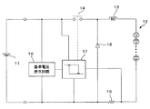
図1は本発明の第1の実施の形態に係わるLED点灯回路の回路図である。直流電源11からの直流で負荷であるLED12が点灯駆動される。直流電源11とLED12との間にはコイル13が直列に接続されている。コイル13は直流電源11からの電流で励磁され、発生する磁束によるエネルギーを蓄積する。コイル13とLED12との接続点から分岐してLED12に並列にスイッチ14が接続され、LED12とスイッチ14との並列回路に対して直列に電流検出抵抗15が接続されている。
(First embodiment)
FIG. 1 is a circuit diagram of an LED lighting circuit according to the first embodiment of the present invention. The
スイッチ14がオンのときには、直流電源11からコイル13およびスイッチ14を通り、さらに電流検出抵抗15を通って直流電源11に戻る閉回路が形成される。一方、スイッチがオフのときには、直流電源11からコイル13およびLED12を通り、さらに電流検出抵抗15を通って直流電源11に戻る閉回路が形成される。電流検出抵抗15は、そのときに形成される閉回路の電流を検出する。
When the
また、直流電源11を電源として所定の基準電圧を発生する基準電圧発生回路16が設けられ、ヒステリシスコンパレータ17にその基準電圧を供給している。ヒステリシスコンパレータ17は、基準電圧をほぼ中心として±方向に動作値と復帰値とを有し、入力信号が動作値未満となると動作し、入力信号が復帰値を超えると復帰する。いま、入力信号を電流検出抵抗で検出された電流値とし、動作および復帰(出力信号)をスイッチ14のオンオフとする。そして、動作値に電流の下限値を予め設定し、復帰値として電流の上限値を予め設定する。そうすると、電流検出抵抗15で検出された電流が上限値を超えたときは、ヒステリシスコンパレータ17はスイッチ14をオフし、電流検出抵抗15で検出された電流値が下限値未満となったときはスイッチ14をオンすることになる。
Further, a reference
このように、LED12の一端を通常の電源回路のように直流電源11のグランド側ではなく、電流検出抵抗15とスイッチ14との接続点に接続する。これにより、電流がスイッチ14側を流れるとき、および負荷であるLED12側を流れるときの双方において、電流検出抵抗15に電流が流れる回路構成としている。従って、スイッチ14のオフ期間を定めるタイマー回路を使用しなくても、ヒステリシスコンパレータ17のみで定電流の制御が可能となる。
In this manner, one end of the
次に動作を説明する。いま、スイッチ14がオンとなったとする。スイッチ14がオンとなると直流電源11からスイッチ14と電流検出抵抗15とを通り直流電源11に戻る閉回路が形成されるので、コイル13に電流が流れる。このとき、コイル13のインダクタンスにより、電流は急激には増加せずに徐々に増加する。この状態はコイル13の励磁状態であり、コイル13にエネルギーが蓄積されつつある状態である。
Next, the operation will be described. Now, assume that the
そして、このときに流れる電流は電流検出抵抗15で検出されてヒステリシスコンパレータ17に入力される。ヒステリシスコンパレータ17では入力した電流の値が予め定められた上限値を超えたかまたは下限値未満となったかを判定する。この電流の値がヒステリシスコンパレータ17の上限値に達したとすると、ヒステリシスコンパレータ17は動作状態から復帰状態に反転しスイッチ14をオフする。スイッチ14がオフとなると、直流電源11からコイル13を経由してLED12側に電流が流れ電流検出抵抗15を通り直流電源11に戻る閉回路が形成される。この閉回路に流れる電流は、コイル13のインダクタンスにより急激には減少せずに徐々に減少する。この状態は、直流電源11からのエネルギーに重畳してコイル13に蓄積されたエネルギーを放出している状態である。
The current flowing at this time is detected by the
このとき、直流電源11およびコイル13からのエネルギーでLED12を点灯する。コイル13からのエネルギーが減少することに伴い、閉回路を流れる電流が徐々に減少して、その電流の値がヒステリシスコンパレータ17の下限値に達したとすると、ヒステリシスコンパレータ17が復帰状態から動作状態に反転し、ヒステリシスコンパレータ17はスイッチ14をオンする。
At this time, the
この動作を繰り返すことにより、電流検出抵抗15を流れる電流値は、ヒステリシスコンパレータ17の上限値と下限値との間に制限され、その平均値はほぼ一定となる。
By repeating this operation, the value of the current flowing through the
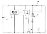
図1では、直流電源11とLED12との間にコイル13を直列に接続し、LED12とスイッチ14との並列回路に対して直列に電流検出抵抗15を接続した場合を示したが、図2に示すように、コイル13と電流検出抵抗15とを直流電源11の極性に対して、鏡像的に接続することも可能である。図1の場合は、スイッチ14がNPN形トランジスタ(N形FET)である場合に有効な回路であり、図2はスイッチ14がPNP形トランジスタ(P形FET)である場合に有効な回路である。 第1の実施の形態によれば、LEDの駆動期間およびコイルの励磁期間の双方において流れる電流を電流検出抵抗15で検出し、ヒステリシスコンパレータ17により、この電流検出抵抗15で検出された電流値が上限値を超えたときはスイッチ14をオフし、電流検出抵抗15で検出された電流値が下限値未満となったときはスイッチ14をオンするので、上限値や下限値との比較だけでLED12に流れる電流をほぼ定電流に制御できる。すなわち、LED12に流れる電流は上限値と下限値との範囲で変動するだけであり、ほぼ定電流に制御できる。従って、スイッチ14のオフ期間を定める発振周波数決定用のタイマー回路が不要となる。
FIG. 1 shows a case where the
また、スイッチ14のオフ期間中のコイル13の逆起電力は、直流電源11の直流電圧に積み増しされる方向となるので、複数個のLED12を直列接続とし、LED12の順方向電圧の和が直流電源11の電源電圧より高い場合に有効である。
Further, since the back electromotive force of the
(第2の実施の形態)
図3は本発明の第2の実施の形態に係わるLED点灯回路の回路図である。この第2の実施の形態は、図1に示した第1の実施の形態に対し、LED12にスイッチ14を並列接続することに代えて、LED12にスイッチ14を直列接続し、ダイオード18を設けて、スイッチ14がオフのときにコイル13とLED12とダイオード18とで閉回路を形成するようにしたものである。また、電流検出抵抗15は、その閉回路のLED12とダイオード18との接続点間に接続され、LED12の駆動期間およびコイル13の励磁期間の双方において流れる電流を検出する。図1と同一要素には同一符号を付し重複する説明は省略する。
(Second Embodiment)
FIG. 3 is a circuit diagram of an LED lighting circuit according to the second embodiment of the present invention. This second embodiment is different from the first embodiment shown in FIG. 1 in that instead of connecting the
図3に示すように、直流電源11とLED12との間には直列にスイッチ14とコイル13とが接続されている。そして、コイル13とスイッチ14との接続点から分岐して、コイル13とLED12との直列回路に並列にダイオード18が接続されている。また、LED12とダイオード18との接続点間に接続されている。
As shown in FIG. 3, a
次に動作を説明する。いま、スイッチ14がオンとなったとする。スイッチ14がオンとなると直流電源11からスイッチ14とコイル13とを通り、さらにLED12と電流検出抵抗15とを通って直流電源11に戻る閉回路が形成されるので、コイル13に電流が流れる。このとき、コイル13のインダクタンスにより、電流は急激には増加せずに徐々に増加する。この状態はコイル13の励磁状態であり、コイル13にエネルギーが蓄積されつつある状態であるとともに、負荷であるLED12を点灯駆動している状態である。
Next, the operation will be described. Now, assume that the
そして、このときに流れる電流は電流検出抵抗15で検出されてヒステリシスコンパレータ17に入力される。ヒステリシスコンパレータ17では入力した電流の値が予め定められた上限値を超えたかまたは下限値未満となったかを判定する。電流の値が徐々に上昇し上限値に達したとすると、ヒステリシスコンパレータ17は動作状態から復帰状態に反転しスイッチ14をオフする。
The current flowing at this time is detected by the
スイッチ14がオフとなると、コイル13からLED12と電流検出抵抗15とを通り、さらにダイオード18を通ってコイル13に戻る閉回路が形成される。この閉回路に流れる電流は、コイル13のインダクタンスにより急激には減少せずに徐々に減少する。この状態はコイル13に蓄積されたエネルギーを放出している状態である。
When the
このとき、コイル13からのエネルギーでLED12を点灯する。コイル13からのエネルギーが減少することに伴い、閉回路を流れる電流が徐々に減少して、その電流の値がヒステリシスコンパレータ17の下限値に達したとすると、ヒステリシスコンパレータ17が復帰状態から動作状態に反転し、ヒステリシスコンパレータ17はスイッチ14をオンする。
At this time, the
この動作を繰り返すことにより、電流検出抵抗15を流れる電流値は、ヒステリシスコンパレータ17の上限値と下限値との間に制限され、その平均値はほぼ一定となる。
By repeating this operation, the value of the current flowing through the
このように、動作原理の基本は、図1に示した第1の実施の形態と概ね同様であるが、LED12に印加される電圧はコイル13の逆起電力となるため、直流電源11の直流電圧より低い値となる。また、LED12を流れる電流は、コイル13の励磁期間中およびスイッチ14のオフ期間中の双方となるため、第1の実施の形態と異なりデューティー比は100%となる。
As described above, the basic principle of the operation is substantially the same as that of the first embodiment shown in FIG. 1, but the voltage applied to the
図3では、直流電源11とLED12との間にスイッチ14およびコイル13を直列に接続し、コイル13とLED12との直列回路に電流検出抵抗15を接続するともにコイル13とスイッチ14との接続点から分岐してダイオード18を接続したが、図4に示すように、LED12、スイッチ14、ダイオード18、電流検出抵抗15の接続関係を直流電源11の極性に対して、鏡像的に接続することも可能である。図3の場合は、スイッチ14がNPN形トランジスタ(N形FET)である場合に有効な回路であり、図4はスイッチ14がPNP形トランジスタ(P形FET)である場合に有効な回路である。 第2の実施の形態によれば、ヒステリシスコンパレータ17の上限値や下限値との比較だけでLED12に流れる電流をほぼ定電流に制御できるので、スイッチ14のオフ期間を定める発振周波数決定用のタイマー回路が不要となる。
In FIG. 3, the
また、LED12に印加される電圧はコイル13の逆起電力となるため、直流電源11の直流電圧より低い値となり、直列に接続されたLED12の順方向電圧の和が直流電源11の電源電圧より低い場合に有効である。
Further, since the voltage applied to the
(第3の実施の形態)
図5は本発明の第3の実施の形態に係わるLED点灯回路の回路図である。この第3の実施の形態は、図1に示した第1の実施の形態に対し、LED12にスイッチ14を並列接続することに代えて、LED12とコイル13との並列回路にスイッチ14を直列接続し、スイッチ14がオフのときにコイル13とLED12とで閉回路を形成するようにしたものである。また、電流検出抵抗15は、その閉回路に接続され、LED12の駆動期間およびコイル13の励磁期間の双方において流れる電流を検出する。図1と同一要素には同一符号を付し重複する説明は省略する。
(Third embodiment)
FIG. 5 is a circuit diagram of an LED lighting circuit according to the third embodiment of the present invention. In the third embodiment, instead of connecting the
図5に示すように、コイル13と電流検出抵抗15とを直列に接続し、さらに、その直列回路とLED12とを並列接続して、その並列回路と直流電源11との間に直列にスイッチ14が接続されている。
As shown in FIG. 5, the
次に動作を説明する。いま、スイッチ14がオンとなったとする。スイッチ14がオンとなると直流電源11からスイッチ14とコイル13とを通り、さらに電流検出抵抗15とを通って直流電源11に戻る閉回路が形成される。これにより、コイル13には電流が流れるがLED12には電流は流れない。これは、図5に示すようにLED12の極性が直流電源11に対し逆極性に接続されているからである。
Next, the operation will be described. Now, assume that the
コイル13に流れる電流は、コイル13のインダクタンスにより急激には増加せずに徐々に増加する。この状態はコイル13の励磁状態であり、コイル13にエネルギーが蓄積されつつある状態である。
The current flowing through the
そして、このときに流れる電流は電流検出抵抗15で検出されてヒステリシスコンパレータ17に入力される。ヒステリシスコンパレータ17では入力した電流の値が予め定められた上限値を超えたかまたは下限値未満となったかを判定する。電流の値が徐々に上昇し上限値に達したとすると、ヒステリシスコンパレータ17は動作状態から復帰状態に反転しスイッチ14をオフする。
The current flowing at this time is detected by the
スイッチ14がオフとなると、コイル13から電流検出抵抗15とLED12とを通ってコイル13に戻る閉回路が形成される。この閉回路に流れる電流は、コイル13のインダクタンスにより急激には減少せずに徐々に減少する。この状態はコイル13に蓄積されたエネルギーを放出している状態である。
When the
このとき、コイル13からのエネルギーでLED12を点灯する。コイル13からのエネルギーが減少することに伴い、閉回路を流れる電流が徐々に減少して、その電流の値がヒステリシスコンパレータ17の下限値に達したとすると、ヒステリシスコンパレータ17が復帰状態から動作状態に反転し、ヒステリシスコンパレータ17はスイッチ14をオンする。
At this time, the
この動作を繰り返すことにより、電流検出抵抗15を流れる電流値は、ヒステリシスコンパレータ17の上限値と下限値との間に制限され、その平均値はほぼ一定となる。
By repeating this operation, the value of the current flowing through the
このように、第3の実施の形態のLED点灯回路は、スイッチ14のオフ期間中のみ負荷であるLED12に電流を流す点で、第2の実施の形態と異なり、この場合のLED12を流れる電流は、第1の実施の形態と同様にデューティー比が約50%となる。
Thus, unlike the second embodiment, the LED lighting circuit of the third embodiment is different from the second embodiment in that a current flows through the
図5では、直流電源とLEDとの間に直列にスイッチを接続し、スイッチとLEDとの接続点に並列にコイルおよび電流検出抵抗を接続したが、図6に示すように、LED12、スイッチ14、電流検出抵抗15の接続関係を直流電源11の極性に対して、鏡像的に接続することも可能である。図5の場合は、スイッチ14がNPN形トランジスタ(N形FET)である場合に有効な回路であり、図6はスイッチ14がPNP形トランジスタ(P形FET)である場合に有効な回路である。 第3の実施の形態によれば、第2の実施の形態と同様に、ヒステリシスコンパレータ17の上限値や下限値との比較だけでLED12に流れる電流をほぼ定電流に制御できるので、スイッチ14のオフ期間を定める発振周波数決定用のタイマー回路が不要となる。
In FIG. 5, a switch is connected in series between the DC power source and the LED, and a coil and a current detection resistor are connected in parallel to the connection point between the switch and the LED. However, as shown in FIG. The connection relationship of the
また、LED12に印加される電圧はコイル13の逆起電力となるため、直流電源11の直流電圧より低い値となり、直列に接続されたLED12の順方向電圧の和が直流電源11の電源電圧より低い場合に有効である。
Further, since the voltage applied to the
11…直流電源、12…LED、13…コイル、14…スイッチ、15…電流検出抵抗、16…基準電圧発生回路、17…ヒステリシスコンパレータ、18…ダイオード
DESCRIPTION OF
Claims (7)
The LED lighting circuit according to claim 6, wherein the connection relationship of the LED, the switch, and the current detection resistor is mirror-connected to the polarity of the DC power supply.
Priority Applications (1)
| Application Number | Priority Date | Filing Date | Title |
|---|---|---|---|
| JP2005293667A JP4749110B2 (en) | 2005-10-06 | 2005-10-06 | LED lighting circuit |
Applications Claiming Priority (1)
| Application Number | Priority Date | Filing Date | Title |
|---|---|---|---|
| JP2005293667A JP4749110B2 (en) | 2005-10-06 | 2005-10-06 | LED lighting circuit |
Publications (2)
| Publication Number | Publication Date |
|---|---|
| JP2007103232A true JP2007103232A (en) | 2007-04-19 |
| JP4749110B2 JP4749110B2 (en) | 2011-08-17 |
Family
ID=38029968
Family Applications (1)
| Application Number | Title | Priority Date | Filing Date |
|---|---|---|---|
| JP2005293667A Expired - Fee Related JP4749110B2 (en) | 2005-10-06 | 2005-10-06 | LED lighting circuit |
Country Status (1)
| Country | Link |
|---|---|
| JP (1) | JP4749110B2 (en) |
Cited By (14)
| Publication number | Priority date | Publication date | Assignee | Title |
|---|---|---|---|---|
| JP2008277079A (en) * | 2007-04-27 | 2008-11-13 | Toko Inc | Led lighting control device |
| JP2009148129A (en) * | 2007-12-18 | 2009-07-02 | Nec Electronics Corp | Dc-dc converter driving circuit |
| JP2009218419A (en) * | 2008-03-11 | 2009-09-24 | Seiko Epson Corp | Driving circuit for semiconductor light-emitting element and light source apparatus using the same, illumination apparatus, monitoring apparatus, and image display apparatus |
| WO2009138478A3 (en) * | 2008-05-14 | 2010-02-11 | Lioris B.V. | Switched-mode power supply, led lighting system and driver comprising the same, and method for electrically driving a load |
| JP2010092776A (en) * | 2008-10-09 | 2010-04-22 | Sharp Corp | Led driving circuit, led illumination fixture, led illumination equipment, and led illumination system |
| JP2011165920A (en) * | 2010-02-10 | 2011-08-25 | Toshiba Lighting & Technology Corp | Led lighting device and illuminating device |
| KR101060801B1 (en) * | 2009-07-15 | 2011-08-30 | 삼성전기주식회사 | LED driving circuit |
| KR101098451B1 (en) | 2007-07-13 | 2011-12-23 | 리치테크 테크놀로지 코포레이션 | Led driver and control method thereof |
| WO2011141206A3 (en) * | 2010-05-10 | 2012-04-26 | Osram Ag | Circuit and method for operating an led lighting unit, and luminaire having such a circuit |
| US8536790B2 (en) | 2008-12-26 | 2013-09-17 | Mitsubishi Electric Corporation | LED lighting device and head lamp LED lighting device |
| WO2014028145A1 (en) * | 2012-08-17 | 2014-02-20 | Trw Automotive U.S. Llc | Method and apparatus to control light intensity as voltage fluctuates |
| US8742681B2 (en) | 2009-11-09 | 2014-06-03 | Toshiba Lighting & Technology Corporation | LED lighting device, illuminating device and power supply therefore having a normally-on type switching element |
| JP2014143048A (en) * | 2013-01-23 | 2014-08-07 | Asahi Kasei Electronics Co Ltd | Led lighting control circuit |
| CN113665475A (en) * | 2021-09-09 | 2021-11-19 | 东风柳州汽车有限公司 | Control method and device for automobile lamp |
Citations (3)
| Publication number | Priority date | Publication date | Assignee | Title |
|---|---|---|---|---|
| JP2000232241A (en) * | 1999-01-22 | 2000-08-22 | Nokia Mobile Phones Ltd | Illuminating electronic device and illumination method |
| JP2005080353A (en) * | 2003-08-29 | 2005-03-24 | Toyoda Gosei Co Ltd | Power supply device for led |
| JP2006147184A (en) * | 2004-11-16 | 2006-06-08 | Mitsubishi Electric Corp | Light-emitting diode lighting device |
-
2005
- 2005-10-06 JP JP2005293667A patent/JP4749110B2/en not_active Expired - Fee Related
Patent Citations (3)
| Publication number | Priority date | Publication date | Assignee | Title |
|---|---|---|---|---|
| JP2000232241A (en) * | 1999-01-22 | 2000-08-22 | Nokia Mobile Phones Ltd | Illuminating electronic device and illumination method |
| JP2005080353A (en) * | 2003-08-29 | 2005-03-24 | Toyoda Gosei Co Ltd | Power supply device for led |
| JP2006147184A (en) * | 2004-11-16 | 2006-06-08 | Mitsubishi Electric Corp | Light-emitting diode lighting device |
Cited By (22)
| Publication number | Priority date | Publication date | Assignee | Title |
|---|---|---|---|---|
| JP4653782B2 (en) * | 2007-04-27 | 2011-03-16 | 旭化成東光パワーデバイス株式会社 | LED lighting control device |
| JP2008277079A (en) * | 2007-04-27 | 2008-11-13 | Toko Inc | Led lighting control device |
| KR101098451B1 (en) | 2007-07-13 | 2011-12-23 | 리치테크 테크놀로지 코포레이션 | Led driver and control method thereof |
| JP2009148129A (en) * | 2007-12-18 | 2009-07-02 | Nec Electronics Corp | Dc-dc converter driving circuit |
| JP2009218419A (en) * | 2008-03-11 | 2009-09-24 | Seiko Epson Corp | Driving circuit for semiconductor light-emitting element and light source apparatus using the same, illumination apparatus, monitoring apparatus, and image display apparatus |
| US8492989B2 (en) | 2008-05-14 | 2013-07-23 | Lioris B.V. | Switched-mode power supply, LED lighting system and driver comprising the same, and method for electrically driving a load |
| WO2009138478A3 (en) * | 2008-05-14 | 2010-02-11 | Lioris B.V. | Switched-mode power supply, led lighting system and driver comprising the same, and method for electrically driving a load |
| JP2010092776A (en) * | 2008-10-09 | 2010-04-22 | Sharp Corp | Led driving circuit, led illumination fixture, led illumination equipment, and led illumination system |
| US8536790B2 (en) | 2008-12-26 | 2013-09-17 | Mitsubishi Electric Corporation | LED lighting device and head lamp LED lighting device |
| JP5721440B2 (en) * | 2008-12-26 | 2015-05-20 | 三菱電機株式会社 | LED lighting device and LED lighting device for headlamp |
| KR101060801B1 (en) * | 2009-07-15 | 2011-08-30 | 삼성전기주식회사 | LED driving circuit |
| US9155143B2 (en) | 2009-11-09 | 2015-10-06 | Toshiba Lighting & Technology Corporation | LED lighting device and illuminating device |
| US8742681B2 (en) | 2009-11-09 | 2014-06-03 | Toshiba Lighting & Technology Corporation | LED lighting device, illuminating device and power supply therefore having a normally-on type switching element |
| US9392655B2 (en) | 2009-11-09 | 2016-07-12 | Toshiba Lighting & Technology Corporation | LED lighting device and illuminating device |
| JP2011165920A (en) * | 2010-02-10 | 2011-08-25 | Toshiba Lighting & Technology Corp | Led lighting device and illuminating device |
| WO2011141206A3 (en) * | 2010-05-10 | 2012-04-26 | Osram Ag | Circuit and method for operating an led lighting unit, and luminaire having such a circuit |
| WO2014028145A1 (en) * | 2012-08-17 | 2014-02-20 | Trw Automotive U.S. Llc | Method and apparatus to control light intensity as voltage fluctuates |
| US9078325B2 (en) | 2012-08-17 | 2015-07-07 | Trw Automotive U.S. Llc | Method and apparatus to control light intensity as voltage fluctuates |
| CN104769354A (en) * | 2012-08-17 | 2015-07-08 | Trw汽车美国有限责任公司 | Method and apparatus to control light intensity as voltage fluctuates |
| EP2885575A4 (en) * | 2012-08-17 | 2016-06-29 | Trw Automotive Us Llc | Method and apparatus to control light intensity as voltage fluctuates |
| JP2014143048A (en) * | 2013-01-23 | 2014-08-07 | Asahi Kasei Electronics Co Ltd | Led lighting control circuit |
| CN113665475A (en) * | 2021-09-09 | 2021-11-19 | 东风柳州汽车有限公司 | Control method and device for automobile lamp |
Also Published As
| Publication number | Publication date |
|---|---|
| JP4749110B2 (en) | 2011-08-17 |
Similar Documents
| Publication | Publication Date | Title |
|---|---|---|
| JP4749110B2 (en) | LED lighting circuit | |
| US7235899B2 (en) | Switching constant-current power supply system | |
| JP4123886B2 (en) | LED lighting device | |
| US8169160B2 (en) | Circuits and methods for driving light sources | |
| US7880393B2 (en) | Power-saving circuit | |
| US8143799B2 (en) | Light emitting diode driving circuit | |
| US8878449B2 (en) | LED drive circuit and LED illumination unit | |
| JP2004186159A (en) | Lighting device | |
| JP6264821B2 (en) | Visible light communication device | |
| JP2005300376A (en) | Voltage detection circuit, power supply device and semiconductor device | |
| JP2009200146A (en) | Led drive circuit and led illumination apparatus using it | |
| US20140346960A1 (en) | Constant power led circuit | |
| JP2009295571A (en) | Light source drive method and light source drive unit | |
| JP2004350390A (en) | Power unit for positive and negative output voltage | |
| EP2312736A3 (en) | Self-Excited Switching Power Supply Circuit | |
| US9763294B2 (en) | Lighting device and lighting fixture using same | |
| JP2010288194A (en) | Drive circuit for semiconductor switching element | |
| KR101517225B1 (en) | Device of operating lighting emitting diode module | |
| JP2011100837A (en) | Self-excitation type led driving circuit | |
| JP5832254B2 (en) | Power supply circuit and earth leakage circuit breaker using the power supply circuit | |
| JP2009261158A (en) | Power supply unit | |
| JP6139360B2 (en) | Light source drive device | |
| JP2015012252A (en) | Current detection circuit | |
| JP5357553B2 (en) | Power supply device and lighting apparatus using the same | |
| TW200613745A (en) | Circuit for driving coil load and optical disk device equipped with the same |
Legal Events
| Date | Code | Title | Description |
|---|---|---|---|
| A621 | Written request for application examination |
Free format text: JAPANESE INTERMEDIATE CODE: A621 Effective date: 20080911 |
|
| A977 | Report on retrieval |
Free format text: JAPANESE INTERMEDIATE CODE: A971007 Effective date: 20110119 |
|
| A131 | Notification of reasons for refusal |
Free format text: JAPANESE INTERMEDIATE CODE: A131 Effective date: 20110301 |
|
| A521 | Written amendment |
Free format text: JAPANESE INTERMEDIATE CODE: A523 Effective date: 20110404 |
|
| A01 | Written decision to grant a patent or to grant a registration (utility model) |
Free format text: JAPANESE INTERMEDIATE CODE: A01 Effective date: 20110510 |
|
| A01 | Written decision to grant a patent or to grant a registration (utility model) |
Free format text: JAPANESE INTERMEDIATE CODE: A01 |
|
| A61 | First payment of annual fees (during grant procedure) |
Free format text: JAPANESE INTERMEDIATE CODE: A61 Effective date: 20110517 |
|
| R150 | Certificate of patent or registration of utility model |
Free format text: JAPANESE INTERMEDIATE CODE: R150 |
|
| FPAY | Renewal fee payment (event date is renewal date of database) |
Free format text: PAYMENT UNTIL: 20140527 Year of fee payment: 3 |
|
| R250 | Receipt of annual fees |
Free format text: JAPANESE INTERMEDIATE CODE: R250 |
|
| LAPS | Cancellation because of no payment of annual fees |