JP2007102766A - Print data generation apparatus - Google Patents
Print data generation apparatus Download PDFInfo
- Publication number
- JP2007102766A JP2007102766A JP2006239711A JP2006239711A JP2007102766A JP 2007102766 A JP2007102766 A JP 2007102766A JP 2006239711 A JP2006239711 A JP 2006239711A JP 2006239711 A JP2006239711 A JP 2006239711A JP 2007102766 A JP2007102766 A JP 2007102766A
- Authority
- JP
- Japan
- Prior art keywords
- printer
- unit
- information
- image data
- Prior art date
- Legal status (The legal status is an assumption and is not a legal conclusion. Google has not performed a legal analysis and makes no representation as to the accuracy of the status listed.)
- Granted
Links
Images


Abstract
Description
本発明は、印刷装置に送るための印刷データを生成するための印刷データ生成装置に関するものである。 The present invention relates to a print data generation apparatus for generating print data to be sent to a printing apparatus.
従来、パーソナルコンピュータ等のコンピュータ(以下「PC」という。)をスキャナ及びプリンタに接続し、前記スキャナで読み取った画像をプリンタに送信し、該プリンタにおいて印刷するシステムが提案されている(例えば、特許文献1参照。)。この場合、スキャナで読み取った画像を前記PCによって、プリンタの用紙サイズなどの基本情報に適したコマンド体系に編集し、編集した印刷データをプリンタに送信する。そして、該プリンタは、その独自の印刷領域で印刷を行うようになっている。
しかしながら、前記従来のシステムにおいては、スキャナで読み取った画像をそのまま印刷しようとすると、プリンタ毎に印刷可能領域、すなわち、印刷保証領域が相違するので、画像の一部が欠落して印刷されてしまうことがあった。 However, in the conventional system, if the image read by the scanner is printed as it is, the printable area, that is, the print guarantee area is different for each printer, so that a part of the image is lost and printed. There was a thing.
図2は従来のシステムを示す図である。 FIG. 2 is a diagram showing a conventional system.
図において、101はスキャナであり、102は該スキャナ101に接続されたPCであり、103は該PC102に接続されたプリンタである。ここで、スキャナ101は、画像105を読み取り、そのデータ、すなわち、読み取りデータをPC102に送信する。なお、前記画像105はA4サイズを示す枠106内に収まっているものとする。そして、PC102で前記読み取りデータをプリンタ103の用紙サイズに適したコマンド体系に編集する。すなわち、コマンド編集を行う。なお、前記用紙サイズはA4サイズであるとする。そして、PC102からコマンド編集が行われた読み取りデータがプリンタ103に送信され、該プリンタ103が受信した読み取りデータをA4サイズの用紙106aにそのまま印刷すると、印刷保証領域107がA4サイズよりも小さいので、一部が欠落した画像105aが印刷されてしまう。
In the figure, 101 is a scanner, 102 is a PC connected to the
本発明は、前記従来の問題点を解決して、印刷装置の印刷保証領域情報を格納する情報格納部と、該情報格納部に格納された印刷保証領域情報に基づいて、画像データを編集する編集部とを有することによって、印刷装置に見合った画像データファイルを作成することができ、画像の一部が欠落することなく印刷を行うことができる印刷データ生成装置を提供することを目的とする。 The present invention solves the above-described conventional problems, and edits image data based on an information storage unit that stores print guarantee area information of a printing apparatus and print guarantee area information stored in the information storage unit It is an object of the present invention to provide a print data generation apparatus that can create an image data file suitable for a printing apparatus and can perform printing without missing a part of the image by having an editing unit. .
そのために、本発明の印刷データ生成装置においては、画像データを印刷する印刷装置に送信する印刷データを生成する印刷データ生成装置であって、前記印刷装置の印刷保証領域情報を格納する情報格納部と、該情報格納部に格納された前記印刷保証領域情報に基づいて前記画像データの編集を行う編集部とを有する。 Therefore, in the print data generation apparatus of the present invention, the print data generation apparatus generates print data to be transmitted to a printing apparatus that prints image data, and an information storage unit that stores print guarantee area information of the printing apparatus And an editing unit that edits the image data based on the print guarantee area information stored in the information storage unit.
本発明によれば、印刷データ生成装置は、印刷装置の印刷保証領域情報を格納する情報格納部と、該情報格納部に格納された印刷保証領域情報に基づいて、画像データを編集する編集部とを有する。これにより、印刷装置に見合った画像データファイルを作成することができ、画像の一部が欠落することなく印刷を行うことができる。 According to the present invention, a print data generation device includes an information storage unit that stores print guarantee area information of a printing apparatus, and an editing unit that edits image data based on the print guarantee area information stored in the information storage unit And have. Accordingly, an image data file suitable for the printing apparatus can be created, and printing can be performed without missing a part of the image.
以下、本発明の実施の形態について図面を参照しながら詳細に説明する。 Hereinafter, embodiments of the present invention will be described in detail with reference to the drawings.
図3は本発明の第1の実施の形態における画像印刷システムの構成の概略を示す図である。 FIG. 3 is a diagram showing an outline of the configuration of the image printing system according to the first embodiment of the present invention.
図において、10は印刷データを生成するための印刷データ生成装置であり、スキャナ装置、ファクシミリ装置、プリンタ及び複写機の機能を併せ持つ複合機等としての多機能複合装置(以下「MFP(複合型プリンタ:Multi Function Printer)」という。)である。そして、該MFP10は、ネットワーク60を介して、画像データを印刷する印刷装置としてのプリンタ50、電子メールを送受信可能なメールサーバ30及びパーソナルコンピュータ等のコンピュータ(以下「PC」という。)40と通信可能に接続されている。
In the figure,
ここで、前記MFP10は、CPU、MPU等の演算手段、半導体メモリ等の記憶手段、液晶ディスプレイ、LED(Light Emitting Diode)ディスプレイ等の表示手段、キーボード、押しボタン、タッチパネル等の入力手段、通信インターフェイス等を備える。 Here, the MFP 10 includes an arithmetic unit such as a CPU and an MPU, a storage unit such as a semiconductor memory, a liquid crystal display, a display unit such as an LED (Light Emitting Diode) display, an input unit such as a keyboard, a push button, and a touch panel, and a communication interface. Etc.
そして、前記プリンタ50は、モノクロ画像を形成するものであっても、カラー画像を形成するものであってもよい。さらに、前記プリンタ50の画像形成方式も、電子写真方式に限らず、いかなるものであってもよく、例えば、インクジェット方式であってもよいし、ワイヤドット方式であってもよいし、インクリボン方式であってもよいし、熱転写方式であってもよい。なお、前記プリンタ50は、CPU、MPU等の演算手段、半導体メモリ等の記憶手段、液晶ディスプレイ、LEDディスプレイ等の表示手段、キーボード、押しボタン、タッチパネル等の入力手段、通信インターフェイス等を備える。
The
また、前記ネットワーク60は、例えば、USB(Universal Serial Bus)ケーブル等のケーブルであってもよいし、イントラネット、LAN(Local Area Network)、WAN(Wide Area Network)等のネットワークであってもよいし、インターネット等を含むIP(Internet Protocol)ネットワークであってもよい。
The
さらに、前記PC40は、CPU、MPU等の演算手段、磁気ディスク、半導体メモリ等の記憶手段、CRT、液晶ディスプレイ等の表示手段、キーボード等の入力手段、通信インターフェイス等を備えるコンピュータであり、例えば、パーソナルコンピュータであるが、いかなるものであってもよい。また、前記メールサーバ30は、CPU、MPU等の演算手段、磁気ディスク、半導体メモリ等の記憶手段、CRT、液晶ディスプレイ等の表示手段、キーボード等の入力手段、通信インターフェイス等を備えるコンピュータとしてのサーバであり、電子メールの送受信を管理する。
Further, the PC 40 is a computer including a calculation means such as a CPU and an MPU, a storage means such as a magnetic disk and a semiconductor memory, a display means such as a CRT and a liquid crystal display, an input means such as a keyboard, a communication interface, etc. Although it is a personal computer, it may be anything. In addition, the
そして、本実施の形態においては、前記MFP10が原稿の画像を読み取り、生成した印刷データを前記ネットワーク60を介して電子メールの添付ファイルとしてメールサーバ30に送信することができ、個人のPC40が電子メールの添付ファイルとして印刷データを受信し、個人のPC40からプリンタ50に印刷データを送信し、プリンタ50が前記原稿の画像データを紙等の媒体に印刷するようになっている。なお、ネットワーク60に接続されているプリンタは単数であっても複数であってもよいが、ここでは、プリンタ50ですべてのプリンタを代表するものとして説明する。
In the present embodiment, the
次に、前記MFP10の構成について説明する。
Next, the configuration of the
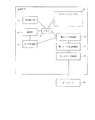
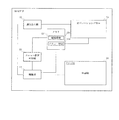
図1は本発明の第1の実施の形態におけるMFPの構成を示すブロック図である。 FIG. 1 is a block diagram showing the configuration of the MFP according to the first embodiment of the present invention.
図1に示されるように、MFP10は、原稿の画像を読み取るための読み取り部11、該読み取り部11によって読み取った画像データを前記プリンタ50の印刷可能領域情報、又は、印刷保証領域情報に基づいて編集処理を行うための編集部14、前記MFP10の設定及びコピーの操作を行うための操作部としてのオペレーションパネル12、プリンタ名や印刷可能領域情報、又は、印刷保証領域情報を格納したり、画像データを編集するための情報格納部としてのメモリ13、前記編集された画像データを画像データファイルとしてのPDF(Portable Document Format)ファイルに変換するためのPDF作成部15、前記オペレーションパネル12での入力情報を基に、前記PDF作成部15で作成したPDFファイルを添付ファイルとする電子メールを作成するための電子メール作成部16、SMTP(Simple Mail Transfer Protocol)を使って電子メールの送信制御を行うための電子メール送信制御部17、及び、TCPIP(Transmission Control Protocol/Internet Protocol)に則って、ネットワーク60を制御するためのネットワーク制御部18を有する。
As shown in FIG. 1, the
ここで、印刷可能領域とは、プリンタ50において、感光体ドラムの幅、露光部のLEDヘッドの幅等によって決定される物理的に印刷が可能な範囲のことである。また、印刷保証領域とは、印刷可能範囲内で、印刷品質を保てるように印刷することができる範囲のことである。なお、印刷可能領域と印刷保証領域とは、同じ場合もあるが相違する場合もあり、一般的には印刷保証領域の方が狭い。
Here, the printable region is a physically printable range determined by the width of the photosensitive drum, the width of the LED head of the exposure unit, and the like in the
また、前記読み取り部11は、CCD(Charge Coupled Device:電荷結合素子)、撮像管等の撮像素子、レンズ、画像が印刷された紙等の媒体、写真等の原稿を照らすランプ等を備え、原稿の画像を走査しながら読み取る装置である。
The
次に、前記オペレーションパネル12の構成について説明する。
Next, the configuration of the
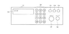
図4は本発明の第1の実施の形態におけるオペレーションパネルの構成を示すブロック図である。本実施の形態においては、印刷保証領域を使用する例を示す。印刷可能領域にも容易に対応できる。 FIG. 4 is a block diagram showing the configuration of the operation panel according to the first embodiment of the present invention. In this embodiment, an example in which a print guarantee area is used will be described. It can easily handle printable areas.
図4に示されるように、オペレーションパネル12は、情報を表示するための表示手段としてのLCD(Liquid Crystal Display)12a、数字やアルファベットなどの文字を入力するための入力手段としての文字入力キー12b、プリンタ名を登録するためのプリンタ登録部12c、該プリンタ登録部12cで登録したプリンタ50毎の印刷保証領域を登録するための印刷保証領域登録部12d、どのプリンタ50の印刷領域に画像データを編集するかを選択するためのプリンタ選択部12e、読み取りの起動や登録の決定を行うためのスタートキー12f、及び、読み取りの停止や登録のキャンセルを行うためのストップキー12gを備えている。
As shown in FIG. 4, the
次に、前記メモリ13の構成について説明する。
Next, the configuration of the
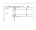
図5は本発明の第1の実施の形態におけるメモリの構成を示すブロック図である。 FIG. 5 is a block diagram showing the configuration of the memory according to the first embodiment of the present invention.
図5に示されるように、メモリ13は、前記オペレーションパネル12で入力された、プリンタ名を格納するためのプリンタ名格納部13a、及び、印刷保証領域を格納するための印刷保証領域格納部13bによって構成されている。なお、該印刷保証領域格納部13bは、上下印刷保証領域及び左右印刷保証領域をそれぞれ格納することができる。また、前記プリンタ名格納部13a及び印刷保証領域格納部13bは、複数のプリンタ50の情報を格納することができるようになっている。図示される例においては、プリンタ名がプリンタA及びプリンタBである2つのプリンタ50の情報が格納されている。更に、本実施の形態においては、A4に対応する印刷保証領域を格納する例を示した。各用紙サイズに対応して格納する。
As shown in FIG. 5, the
次に、前記構成の画像印刷システムの動作について説明する。まず、オペレーションパネル12を操作してプリンタ名及び印刷保証領域を登録する動作について説明する。
Next, the operation of the image printing system having the above configuration will be described. First, an operation for operating the
図6は本発明の第1の実施の形態における読み取り原稿を示す図、図7は本発明の第1の実施の形態における印刷用紙の印刷保証領域を示す図、図8は本発明の第1の実施の形態におけるオペレーションパネルに表示されるメッセージの例を示す第1の図、図9は本発明の第1の実施の形態におけるオペレーションパネルに表示されるメッセージの例を示す第2の図、図10は本発明の第1の実施の形態におけるオペレーションパネルに表示されるメッセージの例を示す第3の図、図11は本発明の第1の実施の形態におけるプリンタ名及び印刷保証領域を登録する動作を示すフローチャートである。 FIG. 6 is a view showing a read original in the first embodiment of the present invention, FIG. 7 is a view showing a print guarantee area of the printing paper in the first embodiment of the present invention, and FIG. 8 is a first view of the present invention. FIG. 9 is a first diagram illustrating an example of a message displayed on the operation panel according to the first embodiment; FIG. 9 is a second diagram illustrating an example of a message displayed on the operation panel according to the first embodiment of the present invention; FIG. 10 is a third diagram illustrating an example of a message displayed on the operation panel according to the first embodiment of the present invention, and FIG. 11 registers a printer name and a print guarantee area according to the first embodiment of the present invention. It is a flowchart which shows the operation | movement to perform.
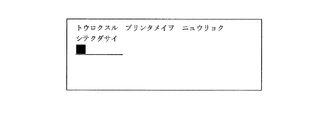
まず、オペレータが、図4に示されるオペレーションパネル12のプリンタ登録部12cを操作し、プリンタ名の登録操作を開始すると、LCD12aに、図8に示されるような「トウロクスル プリンタメイヲ ニュウリョク シテクダサイ」というメッセージが表示される。次に、オペレータが文字入力キー12bを操作してプリンタ名を入力し、スタートキー12fを押すと、入力されたプリンタ名がメモリ13のプリンタ名格納部13aに登録され格納される。この場合、プリンタ名として「プリンタA」を入力すると、図5に示されるように、プリンタ名格納部13aにプリンタ名が格納される。
First, when the operator operates the
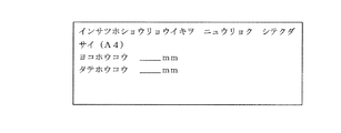
次に、オペレータがオペレーションパネル12の印刷保証領域登録部12dの操作を開始すると、図9に示されるような「プリンタヲ センタク シテクダサイ」というメッセージとともに登録されているプリンタ名がLCD12aに表示される。ここでは、プリンタA及びプリンタBが登録されているものとする。そこで、プリンタAを選択すると、図10に示されるような「インサツホショウリョウイキヲ ニュウリョク シテクダサイ(A4)」というメッセージが表示されるので、オペレータは文字入力キー12bを操作して、プリンタAの左右及び上下方向の印刷保証領域を登録する。すると、登録された内容は、メモリ13の印刷保証領域登録部13bに登録される。
Next, when the operator starts the operation of the print guarantee
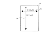
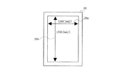
通常、印刷保証領域は印刷可能領域に関係しており、物理的に制限されているものが多く、また、その制限値はプリンタ50によって異なる。つまり、図6及び7に示されるように、読み取り原稿19と印刷用紙20とでは、左右読み取り領域19a>左右印刷保証領域20a、かつ、上下読み取り領域19b>上下印刷保証領域20bという関係にあるので、それぞれ、上下、左右の領域の差分が印刷時に欠落することになる。そこで、プリンタ50のスペックやカタログ等に記載してある印刷保証領域をここで設定する。そして、例えば、前記読み取り原稿19がA4サイズの用紙である場合、図5に示されるように、プリンタ50としてプリンタAを選択し、左右印刷保証領域(ヨコホウコウ)に200〔mm〕、上下印刷保証領域(タテホウコウ)に250〔mm〕と入力するようにする。
Usually, the print guarantee area is related to the printable area, and is often physically limited, and the limit value varies depending on the
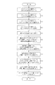
次に、フローチャートについて説明する。
ステップS1 オペレーションパネル12のプリンタ登録部12cを操作し、プリンタ名をメモリ13のプリンタ名格納部13aに登録する。
ステップS2 登録されたプリンタを選択し、オペレーションパネル12の印刷保証領域登録部12dの操作を開始して、プリンタの左右及び上下方向の印刷保証領域を登録して、処理を終了する。
Next, a flowchart will be described.
Step S1: The
Step S2: The registered printer is selected, the operation of the print guarantee
次に、電子メールによって印刷データをMFP10からメールサーバ30に送信する動作について説明する。
Next, an operation for transmitting print data from the
図12は本発明の第1の実施の形態におけるプリンタに表示されるメッセージの例を示す第4の図、図13は本発明の第1の実施の形態におけるプリンタに表示されるメッセージの例を示す第5の図、図14は本発明の第1の実施の形態におけるプリンタに表示されるメッセージの例を示す第6の図、図15は本発明の第1の実施の形態におけるプリンタに表示されるメッセージの例を示す第7の図、図16は本発明の第1の実施の形態における電子メールによって印刷データを送信する動作を示すフローチャートである。 FIG. 12 is a fourth diagram illustrating an example of a message displayed on the printer according to the first embodiment of the present invention, and FIG. 13 is an example of a message displayed on the printer according to the first embodiment of the present invention. FIG. 14 shows a sixth example of a message displayed on the printer according to the first embodiment of the present invention. FIG. 15 shows a message displayed on the printer according to the first embodiment of the present invention. FIG. 7 is a flowchart showing an operation of transmitting print data by electronic mail according to the first embodiment of the present invention.
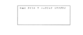
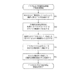
まず、MFP10のオペレーションパネル12に、電子メールの宛(あて)先を入力するためのメッセージ、すなわち、図12に示されるような「E−mail アドレスヲ ニュウリョク シテクダサイ」というメッセージがLCD12aに表示される。そこで、オペレータは文字入力キー12bを操作して、電子メールの宛先を入力する。続いて、図13に示されるような「E−mail タイトル ヲ ニュウリョク シテクダサイ」という電子メールの表題の入力、すなわち、電子メールのタイトルの入力を促すメッセージがLCD12aに表示される。そこで、オペレータは文字入力キー12bを操作して、電子メールの表題を入力する。
First, on the
次に、図14に示されるような「ヒョウジュンノ データ イガイノ ヘンシュウヲオコナウトキハ、 プリンタセンタクキーヲ オシテクダサイ」というメッセージがLCD12aに表示される。すなわち、通常のPDFファイルを作成するか、又は、プリンタ50に合わせて編集するかの選択表示がLCD12aに表示される。そして、オペレータがオペレーションパネル12のプリンタ選択部12eを押すと、図15に示されるような「オツカイノ プリンタヲ センタク シテクダサイ」というメッセージとともに登録されているプリンタ50の装置識別情報としてのプリンタ名がLCD12aに表示される。そこで、オペレータは、画像データをどのプリンタ50で印刷するかを選択する。なお、プリンタ50を選択しない場合には、スタートキー12fを押すと、読み取った画像データを編集せずにそのまま標準のPDFファイルを作成する。
Next, a message such as “Hidden data data” is displayed on the
次に、オペレータがスタートキー12fを押すことによって電子メール送信の起動が行われ、読み取り部11は、画像の読み取りを行い、読み取った画像データをメモリ13に格納する。続いて、前述のようにオペレータによって選択されたプリンタ名に基づいて、メモリ13のプリンタ名格納部13aに格納されているプリンタ名の中からプリンタ50が検索され、検索されたプリンタ50に対応した印刷保証領域情報を印刷保証領域格納部13bから入手する。
Next, when the operator presses the start key 12 f, e-mail transmission is activated, and the
次に、編集部14は、前記印刷保証領域情報に基づき、メモリ13に格納された画像データを前記保証可能領域を考慮した大きさになるように編集を行う。例えば、図6の読み取り原稿19は、左右読み取り領域19aが210〔mm〕で、上下読み取り領域19bが297〔mm〕である。そして、図5に示されるプリンタAが選択された場合、図7に示されるように、印刷用紙20の印刷保証領域は、左右印刷保証領域20aが200〔mm〕で、上下印刷保証領域20bが250〔mm〕である。そこで、編集部14は、印刷保証領域に収まるように、画像データの縮小処理を行う。例えば、画像全体を250/297倍縮小したり、上下は250/297倍、左右は20/21倍にしてもよい。そして、PDF作成部15は、編集された画像データをPDFファイルに変換する。
Next, the
続いて、電子メール作成部16は、オペレーションパネル12を操作することによって入力された宛先及び表題を備え、PDF作成部15によって作成されたPDFファイルを添付ファイルとする電子メールを作成する。そして、電子メール送信制御部17は、標準の電子メールを送信するときに使われるSMTPを使用し、前記電子メールの送信制御を行う。さらに、ネットワーク制御部18はネットワーク通信を行うときに使われる標準のTCPIPに則ってネットワーク60を制御することによって、電子メールがメールサーバ30に送信される。
Subsequently, the
次に、フローチャートについて説明する。
ステップS11 オペレーションパネル12の文字入力キー12bを操作して電子メールの宛先を入力する。
ステップS12 オペレーションパネル12の文字入力キー12bを操作して電子メールの表題を入力する。
ステップS13 オペレーションパネル12の文字入力キー12bを操作してどのプリンタ50で印刷するかを選択する。
ステップS14 オペレーションパネル12の文字入力キー12bを操作して電子メール送信のスタートキー12fを押す。
ステップS15 読み取り部11は、画像データの読み取りを行う。
ステップS16 選択されたプリンタ名に基づいて、メモリ13のプリンタ名格納部13aに格納されているプリンタ名の中からプリンタ50が検索され、検索されたプリンタ50に対応した印刷保証領域情報を入手する。
ステップS17 編集部14は、前記印刷保証領域情報に基づき、メモリ13に格納された画像データを前記印刷保証領域を考慮した大きさになるように編集を行う。
ステップS18 PDF作成部15は、編集された画像データをPDFファイルに変換する。
ステップS19 電子メール作成部16は、オペレーションパネル12を操作することによって入力された宛先及び表題を備え、PDF作成部15によって作成されたPDFファイルを添付ファイルとする電子メールを作成する。
ステップS20 電子メール送信制御部17はSMTPを使用し、電子メールの送信制御を行う。
ステップS21 ネットワーク制御部18によって、電子メールがメールサーバ30に送信され、処理を終了する。
Next, a flowchart will be described.
Step S11: The character input key 12b of the
Step S12: The title of the e-mail is input by operating the character input key 12b of the
Step S13 The character input key 12b of the
Step S14: The character input key 12b on the
Step S15 The
Step S16: Based on the selected printer name, the
Step S <b> 17 The
Step S18 The
Step S19 The
Step S20: The e-mail
Step S21 An e-mail is transmitted to the
このように、本実施の形態においては、印刷データ生成装置としてのMFP10が、プリンタ50の印刷保証領域情報を格納するメモリ13と、該メモリ13に格納された印刷保証領域情報に基づいて前記画像データを編集する編集部14とを有する。そのため、MFP10がプリンタ50に見合ったPDFファイルを作成することができるので、プリンタ50が印刷を行うときに、画像の一部が欠落することがない。本実施の形態においては、MFPの別体のプリンタの例を示したが、MFPが有するプリンタであってもよい。すなわち、画像データがスキャンされ、メール送信ではなく印刷が指示されると、MFP自体の有するプリンタに応じた印刷保証領域情報に基づき編集処理を行う。そして、編集された画像データはMFPプリンタ部に送信され印刷される。MFP自体のプリンタの印刷保証領域情報は、あらかじめMFPの印刷保証領域情報格納部に格納されている。
As described above, in the present embodiment, the
次に、本実施の形態の変形例について説明する。 Next, a modification of the present embodiment will be described.
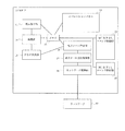
図17は本発明の第1の実施の形態の変形例におけるMFPの構成を示すブロック図である。 FIG. 17 is a block diagram showing a configuration of the MFP according to a modification of the first embodiment of the present invention.
図17に示されるように、MFP10は、読み取り部11、オペレーションパネル12、メモリ13、編集部14、メニュー設定判断部23及び印刷部24を有する。
As illustrated in FIG. 17, the
ここで、読み取り部11は、前記第1の実施の形態における読み取り部11と同様のものであり、図示されない原稿台にセットされた原稿を走査しながら読み取り、画像データを生成する。また、オペレーションパネル12は、前記第1の実施の形態におけるオペレーションパネル12と同様のものであり、機能の観点から、コピーの指定、装置メニューの設定等の指示情報を入力する入力部と、装置状態情報、装置メニュー項目等を表示する表示部とを有する。
Here, the
そして、メモリ13は、プリンタ50毎又は用紙サイズ毎の印刷可能領域情報を格納する印刷可能領域情報テーブル13c、及び、装置メニューの各種設定情報を格納するメニュー設定情報格納部13dを有する。また、メニュー設定判断部23は、メモリ13のメニュー設定情報格納部13dからサイズ調整メニューの設定値を読み出し、有効に設定されているのか、無効に設定されているのかを判断する。
The
さらに、編集部14は、サイズ調整メニューが調整有効に設定されている場合、MFP10内のプリンタである印刷部24の印刷可能領域情報であって、原稿サイズに対応した用紙サイズと対となる印刷可能領域情報を読み出し、その印刷可能領域のサイズに基づき、読み取り部11から渡された画像データを編集する。また、サイズ調整メニューが調整無効に設定されている場合には、読み取り部11から渡された画像データを編集せずに、そのまま印刷部24へ出力する。
Further, when the size adjustment menu is set to enable adjustment, the
そして、該印刷部24は、編集部14から渡された画像データを印刷可能なビットマップデータに変換し、内蔵する図示されないプリンタエンジンに渡すことによってMPF10に格納された媒体に画像データを印刷する。なお、印刷部24は、ネットワーク60に接続されているプリンタ50と同様のものであるが、MFP10内に配設されているプリンタであり、プリンタ名がプリンタXである。
The
次に、前記メモリ13の構成について説明する。
Next, the configuration of the
図18は本発明の第1の実施の形態の変形例におけるメモリの印刷可能領域情報テーブルの構成を示すブロック図である。 FIG. 18 is a block diagram showing the configuration of the printable area information table in the memory according to the modification of the first embodiment of the present invention.
印刷可能領域情報テーブル13cには、MFP10の初期設定においては、プリンタ名がプリンタXである印刷部24の情報のみが登録されている。なお、プリンタAの情報は、前記第1の実施の形態で説明したように、オペレータによって登録されたり、プリンタAとの通信により取得されることによって登録される。
In the printable area information table 13c, in the initial setting of the
この場合、印刷可能領域情報テーブル13cには、プリンタ50毎に複数の用紙サイズに対応した印刷可能領域情報が格納されている。
In this case, printable area information corresponding to a plurality of paper sizes for each
次に、本変形例における画像印刷システムの動作について説明する。 Next, the operation of the image printing system in this modification will be described.
図19は本発明の第1の実施の形態の変形例におけるサイズ調整メニュー項目の表示を示す図、図20は本発明の第1の実施の形態の変形例における原稿をコピーする動作を示すフローチャートである。 FIG. 19 is a diagram showing the display of the size adjustment menu item in the modification of the first embodiment of the present invention, and FIG. 20 is a flowchart showing the operation of copying a document in the modification of the first embodiment of the present invention. It is.
まず、オペレータは、コピーすべき原稿をMFP10の図示されない原稿台にセットする。続いて、オペレータは、オペレーションパネル12を操作してコピーの指定を行う。すると、読み取り部11は、コピーの指定に基づき、原稿台にセットされた原稿を走査しながら読み取り、画像データを生成する。
First, the operator sets a document to be copied on a document table (not shown) of the
次に、MFP10は、メモリ13のメニュー設定情報格納部13dに格納されているサイズ調整メニュー項目に対応する設定値を読み出し、サイズ調整メニューが有効に設定されているか否かを判断する。なお、オペレーションパネル12には、図19に示されるように、サイズ調整メニューが有効であるか無効であるかが表示されている。そして、図19に示される例のように、サイズ調整が有効に設定されている場合、メモリ13の印刷可能領域情報テーブル13cから、原稿の用紙サイズ、すなわち、原稿サイズに応じた印刷可能領域情報を取得する。この場合、オペレータがオペレーションパネル12を操作してコピーの指定を行っているので、MFP10に配設されているプリンタとしての印刷部24の印刷可能領域情報を取得する。また、原稿サイズに応じて印刷に使用する媒体の用紙サイズが選択され、その選択された用紙サイズに対応する印刷可能領域情報が取得される。
Next, the
次に、編集部14は、取得した印刷可能領域情報に基づき、読み取り部11から渡された画像データが印刷可能領域内に収まるように画像データを編集し、編集した画像データを印刷部24に渡す。すると、該印刷部24は渡された画像データを印刷出力する。これにより、処理が終了する。
Next, the
一方、サイズ調整メニューが有効に設定されているか否かを判断して、サイズ調整が無効に設定されている場合、編集部14は、印刷可能領域内に収まるように画像データを編集することなく、そのまま印刷部24に渡す。すると、該印刷部24はそのまま画像データを印刷出力する。
On the other hand, it is determined whether or not the size adjustment menu is set to be valid, and when the size adjustment is set to be invalid, the
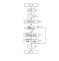
次に、フローチャートについて説明する。
ステップS31 原稿をセットする。
ステップS32 コピーを指定する。
ステップS33 原稿を読み取る。
ステップS34 サイズ調整メニューが有効に設定しているか否かを判断する。サイズ調整メニューが有効に設定している場合はステップS35へ進み、サイズ調整メニューが有効に設定していない場合はステップS37へ進む。
ステップS35 原稿サイズに応じた印刷可能領域情報を取得する。
ステップS36 印刷可能領域情報に基づき画像データの編集を行う。
ステップS37 印刷を行い、処理を修了する。
Next, a flowchart will be described.
Step S31 A document is set.
Step S32: Specify copy.
Step S33 Read the document.
Step S34: to judge whether the size adjustment menu is set valid. If the size adjustment menu is set to be valid, the process proceeds to step S35, and if the size adjustment menu is not set to be valid, the process proceeds to step S37.
Step S35 Printable area information corresponding to the document size is acquired.
Step S36: The image data is edited based on the printable area information.
Step S37: Printing is completed.
なお、本変形例においては、装置メニューの設定によってサイズ調整が有効に設定されているか無効に設定されているかを判断する場合について説明したが、装置メニューを設けることなく、読み取り部11が生成した画像データのサイズを印刷に使用する媒体の用紙サイズに対応する印刷可能領域サイズと比較し、読み取り部11が生成した画像データのサイズが印刷に使用する媒体の用紙サイズに対応する印刷可能領域サイズより大きい場合には画像データを編集し、小さい場合には画像データを編集しないようにしてもよい。
In this modification, the case where it is determined whether the size adjustment is set to valid or invalid by the setting of the device menu has been described. However, the
また、本変形例においては、コピー動作について説明したが、前記第1の実施の形態のように電子メールを送信する場合においても、プリンタとして印刷部24を選択することもできる。
In the present modification, the copying operation has been described. However, even when an e-mail is transmitted as in the first embodiment, the
次に、本発明の第2の実施の形態について説明する。なお、第1の実施の形態と同じ構造を有するものについては、同じ符号を付与することによってその説明を省略する。また、前記第1の実施の形態と同じ動作及び同じ効果についても、その説明を省略する。 Next, a second embodiment of the present invention will be described. In addition, about what has the same structure as 1st Embodiment, the description is abbreviate | omitted by providing the same code | symbol. The description of the same operation and the same effect as those of the first embodiment is also omitted.
図21は本発明の第2の実施の形態におけるMFPの構成を示すブロック図である。 FIG. 21 is a block diagram showing a configuration of the MFP according to the second embodiment of the present invention.
本実施の形態において、MFP10は、図21に示されるように、ネットワーク60上のプリンタ50を認識するためのMIB(Management Information Base)を生成し、ネットワーク60上に存在するプリンタ50を特定した後に、各プリンタ50に対して、印刷保証領域情報を返信するように要求するためのPJL(Printer Job Language)コマンドを生成するMIB/PJLコマンド制御部21、及び、プリンタ50からの応答があったMIB及びPJLコマンドを解析するMIB/PJLコマンド解析部22を更に有する。なお、その他の点の構成については、前記第1の実施の形態と同様であるので説明を省略する。
In the present embodiment, as shown in FIG. 21, the
次に、本実施の形態におけるプリンタ50の構成について説明する。
Next, the configuration of the
図22は本発明の第2の実施の形態におけるプリンタの構成を示すブロック図である。 FIG. 22 is a block diagram showing the configuration of the printer according to the second embodiment of the present invention.
図22に示されるように、プリンタ50は、ネットワーク60から受信したMIB及びPJLコマンドを解析するためのMIB/PJLコマンド解析部51、該MIB/PJLコマンド解析部51で解析した結果が、装置識別情報としてのプリンタ名の問い合わせである場合に、プリンタ名をMIBの応答として作成したり、前記MIB/PJLコマンド解析部51で解析した結果が、印刷保証領域情報を要求するPJLである場合に、印刷保証領域をPJLコマンドの応答として作成するためのMIB/PJLコマンド制御部52、ネットワーク60の通信制御を行うためのネットワーク制御部53、プリンタ言語を解釈するためのエミュレーション部55、及び、印刷制御を行うための印刷部54を有する。
As shown in FIG. 22, the
次に、本実施の形態における画像印刷システムの動作について説明する。 Next, the operation of the image printing system in the present embodiment will be described.
図23は本発明の第2の実施の形態における画像印刷システムのシーケンスを示す図、図24は本発明の第2の実施の形態における画像印刷システムの動作を示すフローチャートである。 FIG. 23 is a diagram showing a sequence of the image printing system according to the second embodiment of the present invention, and FIG. 24 is a flowchart showing an operation of the image printing system according to the second embodiment of the present invention.
前記第1の実施の形態において、メモリ13のプリンタ名格納部13a及び印刷保証領域格納部13bへの情報の登録は、オペレータがオペレーションパネル12の文字入力キー12bを操作することによって行われた。これに対し、本実施の形態においては、ネットワーク60を介して接続されたプリンタ50と通信することによって取得した情報をメモリ13のプリンタ名格納部13a及び印刷保証領域格納部13bへ登録するようになっている。すなわち、各プリンタは各自の印刷保証領域情報を保持している。
In the first embodiment, information is registered in the printer
まず、MFP10のMIB/PJLコマンド制御部22がネットワーク60上の接続可能なプリンタ50を検索するためのMIBコマンドを作成し、ネットワーク制御部18が前記MIBコマンドをネットワーク60上でブロードキャスト送信し、その応答をMIB/PJLコマンド解析部22が解析することによってプリンタ50の検索を実行する。
First, the MIB / PJL
ブロードキャストに応答したプリンタに対して、例えば、図23に示されるように、MFP10がネットワーク60上にあるプリンタAとプリンタBに対して、MIBコマンドを送信する場合、まず、MFP10はプリンタ名問い合わせMIBをプリンタBに送信し、該プリンタBからプリンタ名を受信する。同様に、MFP10はプリンタ名問い合わせMIBをプリンタAに送信し、該プリンタAからプリンタ名を受信する。
For example, when the
次に、接続可能なプリンタ50を検索することができた場合、MFP10のMIB/PJLコマンド制御部21は、印刷保証領域情報を取得するためのPJLコマンドを作成し、ネットワーク制御部18が、検索されたプリンタ50に対して、作成したPJLコマンドを送信する。
Next, when the
ここで、例えば、プリンタBはPJLをサポートしていないプリンタであり、プリンタAはPJLをサポートしているプリンタであるとする。そして、MFP10は、プリンタ名を認識することによって、PJLをサポートしているプリンタであるか否かを判断することができるものとする。なお、MFP10は、各プリンタ50に対して能力の問い合わせを行うようにしてもよい。そして、プリンタ名問い合わせMIBに対してプリンタAという応答を受け取った後に、MFP10は、印刷保証領域問い合わせPJLをプリンタAに送信し、プリンタAから左右印刷保証領域20a及び上下印刷保証領域20bの応答を受信する。
Here, for example, the printer B is a printer that does not support PJL, and the printer A is a printer that supports PJL. The
続いて、MFP10は、プリンタAから受信した印刷保証領域情報を含んだPJLの応答コマンドをMIB/PJLコマンド解析部22で解析し、プリンタ名をメモリ13のプリンタ名格納部13aに格納し、印刷保証領域情報を印刷保証領域格納部13bに格納する。
Subsequently, the
なお、その他の動作については、前記第1の実施の形態と同様であるので説明を省略する。 Since other operations are the same as those in the first embodiment, description thereof will be omitted.
次に、図23に示されるシーケンスのステップについて説明する。
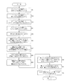
ステップS41 MFP10はプリンタ名問い合わせMIBをプリンタBに送信する。
ステップS42 MFP10はプリンタBからプリンタ名を受信する。
ステップS43 MFP10はプリンタ名問い合わせMIBをプリンタAに送信する。
ステップS44 MFP10はプリンタAからプリンタ名を受信する。
ステップS45 MFP10は印刷保証領域問い合わせPJLをプリンタAに送信する。
ステップS46 MFP10はプリンタAから左右印刷保証領域20a及び上下印刷保証領域20bの応答を受信する。
Next, steps of the sequence shown in FIG. 23 will be described.
Step S41 The
Step S42: The
Step S43 The
Step S44 The
Step S45 The
Step S46 The
次に、図24に示されるフローチャートについて説明する。
ステップS51 MIB/PJLコマンド解析部22がネットワーク60上の接続可能なプリンタ50を検索する。
ステップS52 MFP10のMIB/PJLコマンド制御部21は、印刷保証領域情報を取得するためのPJLコマンドを作成する。
ステップS53 ネットワーク制御部18が、検索されたプリンタ50に対して、作成したPJLコマンドを送信する。
ステップS54 プリンタから受信した印刷保証領域情報を含んだPJLの応答コマンドをMIB/PJLコマンド解析部22で解析する。
ステップS55 印刷保証領域情報をメモリ13の印刷保証領域格納部13bに格納して、処理を終了する。
Next, the flowchart shown in FIG. 24 will be described.
Step S51 The MIB / PJL
Step S52 The MIB / PJL
Step S53 The
Step S54 The MIB / PJL
Step S55 The print guarantee area information is stored in the print guarantee
このように、本実施の形態においては、接続可能なプリンタ50の装置識別情報及びプリンタ50毎の印刷保証領域情報を、MFP10とプリンタ50との間で特定のコマンドを用いて通信することによって取得し、取得した情報をメモリ13に格納するようになっている。そのため、オペレーションパネル12を操作してプリンタ50の装置識別情報及び印刷保証領域情報を入力する必要がなく、使い勝手が向上する。なお、その他の点の効果については、前記第1の実施の形態と同様である。
As described above, in this embodiment, the device identification information of the
次に、本発明の第3の実施の形態について説明する。なお、第1及び第2の実施の形態と同じ構造を有するものについては、同じ符号を付与することによってその説明を省略する。また、前記第1及び第2の実施の形態と同じ動作及び同じ効果についても、その説明を省略する。 Next, a third embodiment of the present invention will be described. In addition, about the thing which has the same structure as 1st and 2nd embodiment, the description is abbreviate | omitted by providing the same code | symbol. Also, the description of the same operations and effects as those of the first and second embodiments is omitted.
図25は本発明の第3の実施の形態における電子メール作成部の構成を示すブロック図である。 FIG. 25 is a block diagram showing the configuration of the e-mail creation unit in the third embodiment of the present invention.
本実施の形態におけるMFP10の電子メール作成部16は、図25に示されるように、オペレーションパネル12の操作によって入力された情報に基づいて電子メールの表題を作成するための電子メール表題作成部16a、オペレーションパネル12の操作によって入力された電子メールの表題に選択されたプリンタ名を付加した表題を作成するためのプリンタ名付加部16b、オペレーションパネル12の操作によって入力された情報に基づいて電子メールの添付ファイルの名前を作成するための添付ファイル名作成部16c、及び、オペレーションパネル12の操作によって入力された電子メールの表題に選択されたプリンタ50の装置識別子情報としてのプリンタ名を付加した添付ファイル名を作成するためのプリンタ名付加部16dを備える。なお、その他の点の構成については、前記第1の実施の形態と同様であるので説明を省略する。
As shown in FIG. 25, the
次に、本実施の形態における画像印刷システムの動作について説明する。 Next, the operation of the image printing system in the present embodiment will be described.
図26は本発明の第3の実施の形態における電子メール作成部で作成される電子メールの内容の例を示す図、図27は本発明の第3の実施の形態における作成した印刷データを電子メールでメールサーバに送信する動作を示すフローチャートである。 FIG. 26 is a diagram showing an example of the contents of an e-mail created by the e-mail creating unit in the third embodiment of the present invention, and FIG. 27 shows the print data created in the third embodiment of the present invention as electronic data. It is a flowchart which shows the operation | movement transmitted to a mail server with mail.
まず、オペレータは、MFP10のオペレーションパネル12を操作して電子メールの宛先を入力し、電子メールの表題と添付ファイルの名称とを入力する。次に、オペレータは、オペレーションパネル12を操作してプリンタ名を選択し、オペレーションパネル12を操作して電子メール送信の起動を行う。すると、読み取り部11が画像の読み取りを行い、読み取られた画像データはメモリ13に格納される。
First, the operator operates the
続いて、選択されたプリンタ名に基づいて、メモリ13のプリンタ名格納部13aに格納してあるプリンタ名の中から検索し、それに対応した印刷保証領域情報を印刷保証領域格納部13bから入手する。
Subsequently, based on the selected printer name, the printer name stored in the printer
次に、編集部14は、前記印刷保証領域情報に基づき、メモリ13に格納された画像データを前記印刷保証領域を考慮した大きさとするように編集を行う。そして、PDF作成部15は、編集された画像データをPDFファイルに変換する。
Next, the
続いて、電子メール作成部16の電子メール表題作成部16aは、オペレーションパネル12を操作して入力された情報に基づき、電子メールの表題を作成し、プリンタ名付加部16bは、オペレーションパネル12を操作して選択されたプリンタ名を前記表題に付加する。
Subsequently, the e-mail
また、電子メール作成部16の添付ファイル名作成部16cは、オペレーションパネル12を操作して入力された情報に基づき、電子メールの添付ファイルの名前を作成し、プリンタ名付加部16dは、オペレーションパネル12を操作して入力された添付ファイル名に、選択されたプリンタ名を付加した添付ファイル名を作成する。そして、電子メール作成部16は、オペレーションパネル12を操作して入力された宛先と作成した表題を添付ファイルに基づき、電子メールを作成する。
The attached file
そして、電子メール送信制御部17は、標準の電子メールを送信するときに使われるSMTPを使用して電子メールの送信制御を行う。さらに、ネットワーク制御部18はネットワーク通信を行うときに使われる標準のTCPIPに則ってネットワーク60を制御することによって、電子メールがメールサーバ30に送信される。
Then, the e-mail
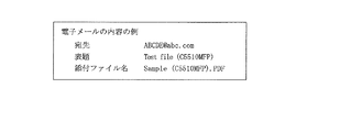
なお、図26に示されるような内容の電子メールが、電子メール作成部16によって作成される。図26に示される例は、オペレーションパネル12を操作することによって、表題としての「Test file」、添付ファイル名としての「Sample」が入力され、プリンタ名として「C5510MFP」が選択された場合の例である。
Note that an e-mail having contents as shown in FIG. 26 is created by the
この場合、表題がTest file(C5510MFP)となり、添付ファイル名がSample(C5510MFP).PDFとなるので、電子メールを受信したユーザは、どのプリンタ用の印刷データかを即座に判別することができる。 In this case, the title is Test file (C5510MFP) and the attached file name is Sample (C5510MFP). Since it becomes PDF, the user who receives the e-mail can immediately determine which printer the print data is for.
次に、フローチャートについて説明する。
ステップS61 オペレーションパネル12を操作して電子メールの宛先を入力する。
ステップS62 オペレーションパネル12を操作して電子メールの表題と添付ファイルの名称とを入力する。
ステップS63 オペレーションパネル12を操作してプリンタ名を選択する。
ステップS64 オペレーションパネル12を操作して電子メール送信のスタートキー12fを押す。
ステップS65 読み取り部11は、画像データの読み取りを行う。
ステップS66 選択されたプリンタ名に基づいて、メモリ13のプリンタ名格納部13aに格納されているプリンタ名の中からプリンタ50が検索され、検索されたプリンタ50に対応した印刷保証領域情報を入手する。
ステップS67 編集部14は、前記印刷保証領域情報に基づき、メモリ13に格納された画像データを前記印刷保証領域を考慮した大きさになるように編集を行う。
ステップS68 PDF作成部15は、編集された画像データをPDFファイルに変換する。
ステップS69 電子メール作成部16の電子メール表題作成部16aは、オペレーションパネル12を操作して入力された情報に基づき、電子メールの表題を作成し、プリンタ名付加部16bは、オペレーションパネル12を操作して選択されたプリンタ名を付加した表題を作成する。
ステップS70 電子メール作成部16の添付ファイル名作成部16cは、オペレーションパネル12を操作して入力された情報に基づき、電子メールの添付ファイルの名前を作成し、プリンタ名付加部16dは、オペレーションパネル12を操作して入力された添付ファイル名に、選択されたプリンタ名を付加した添付ファイル名を作成する。
ステップS71 電子メール作成部16は、オペレーションパネル12を操作することによって入力された宛先及び表題を備え、PDF作成部15によって作成されたPDFファイルを添付ファイルとする電子メールを作成する。
ステップS72 電子メール送信制御部17はSMTPを使用し、電子メールの送信制御を行う。
ステップS73 ネットワーク制御部18によって、電子メールがメールサーバ30に送信され、処理を終了する。
Next, a flowchart will be described.
Step S61: The
Step S62: The
Step S63: The printer name is selected by operating the
Step S64: The
Step S65 The
Step S66: Based on the selected printer name, the
Step S67: The editing
Step S68 The
Step S69 The e-mail
Step S70 The attached file
Step S71 The
Step S72: The e-mail
Step S73: The
このように、本実施の形態においては、印刷データ生成装置としてのMFP10のオペレーションパネル12を操作することによって選択されたプリンタ50の装置識別子情報を電子メールの添付ファイルの名称及び電子メールの表題に付加するようになっている。そのため、添付ファイルをどのプリンタ50で印刷するのが最適であるかを可視的に判断することができるので、使い勝手が向上する。また、メールの本文中に選択されたプリンタ名を入れてもよい。
As described above, in the present embodiment, the device identifier information of the
次に、本発明の第4の実施の形態について説明する。なお、第1〜第3の実施の形態と同じ構造を有するものについては、同じ符号を付与することによってその説明を省略する。また、前記第1〜第3の実施の形態と同じ動作及び同じ効果についても、その説明を省略する。 Next, a fourth embodiment of the present invention will be described. In addition, about the thing which has the same structure as the 1st-3rd embodiment, the description is abbreviate | omitted by providing the same code | symbol. Explanation of the same operations and effects as those of the first to third embodiments is also omitted.
まず、本実施の形態におけるMFP10の構成について説明する。
First, the configuration of
図28は本発明の第4の実施の形態におけるMFPの構成を示すブロック図である。 FIG. 28 is a block diagram showing the configuration of the MFP according to the fourth embodiment of the present invention.
本実施の形態におけるMFP10のPDF作成部15は、図28に示されるように、編集部14で画像データの編集処理を施したことを意味する情報をPDFファイルのヘッダ部に付加するための編集済み情報付加部15aを有する。なお、その他の点の構成については、前記第2の実施の形態と同様であるので説明を省略する。
As shown in FIG. 28, the
次に、本実施の形態におけるプリンタ50の構成について説明する。
Next, the configuration of the
図29は本発明の第4の実施の形態におけるプリンタの構成を示すブロック図である。 FIG. 29 is a block diagram showing a configuration of a printer according to the fourth embodiment of the present invention.
図29に示されるように、プリンタ50のエミュレーション部55は、PDFファイルのヘッダ部から編集済みの情報を見つけるための編集済み情報認識部55aを有する。なお、その他の点の構成については、前記第2の実施の形態と同様であるので説明を省略する。
As shown in FIG. 29, the
次に、本実施の形態における画像印刷システムの動作について説明する。 Next, the operation of the image printing system in the present embodiment will be described.
図30は本発明の第4の実施の形態における作成した印刷データを電子メールでメールサーバに送信する動作を示すフローチャートである。 FIG. 30 is a flowchart showing an operation of transmitting the created print data to the mail server by e-mail according to the fourth embodiment of the present invention.
なお、画像を読み取り、画像データを編集してPDFファイルに変換するまでの動作については、前記第1の実施の形態と同様であるので説明を省略する。 The operation from reading an image, editing the image data, and converting the image data into a PDF file is the same as that in the first embodiment, and a description thereof will be omitted.
そして、PDF作成部15は、編集部14によって編集された画像データをPDFファイルに変換する。続いて、編集済み情報付加部15aは、PDFファイルのヘッダ部に編集済みを意味する情報を付加する。なお、以降の動作についても、前記第1の実施の形態と同様であるので説明を省略する。
Then, the
次に、フローチャートについて説明する。
ステップS81 オペレーションパネル12の文字入力キー12bを操作して電子メールの宛先を入力する。
ステップS82 オペレーションパネル12の文字入力キー12bを操作して電子メールの表題を入力する。
ステップS83 オペレーションパネル12の文字入力キー12bを操作してどのプリンタ50で印刷するかを選択する。
ステップS84 オペレーションパネル12の文字入力キー12bを操作して電子メール送信のスタートキー12fを押す。
ステップS85 読み取り部11は、画像データの読み取りを行う。
ステップS86 選択されたプリンタ名に基づいて、メモリ13のプリンタ名格納部13aに格納されているプリンタ名の中からプリンタ50が検索され、検索されたプリンタ50に対応した印刷保証領域情報を入手する。
ステップS87 編集部14は、前記印刷保証領域情報に基づき、メモリ13に格納された画像データを前記印刷保証領域を考慮した大きさになるように編集を行う。
ステップS88 PDF作成部15は、編集された画像データをPDFファイルに変換する。
ステップS89 編集済み情報付加部15aは、PDFファイルのヘッダ部に編集済みを意味する情報を付加する。
ステップS90 電子メール作成部16は、オペレーションパネル12を操作することによって入力された宛先及び表題を備え、PDF作成部15によって作成されたPDFファイルを添付ファイルとする電子メールを作成する。
ステップS91 電子メール送信制御部17はSMTPを使用し、電子メールの送信制御を行う。
ステップS92 ネットワーク制御部18によって、電子メールがメールサーバ30に送信され、処理を終了する。
Next, a flowchart will be described.
Step S81: The character input key 12b of the
Step S82 The e-mail title is input by operating the character input key 12b of the
Step S83 The character input key 12b of the
Step S84: The character input key 12b on the
Step S85 The
Step S86: Based on the selected printer name, the
Step S87: The editing
Step S88 The
Step S89 The edited information adding unit 15a adds information meaning edited to the header portion of the PDF file.
Step S90 The
Step S91: The e-mail
Step S92 The
次に、PDFファイルを受信したプリンタ50の動作について説明する。
Next, the operation of the
図31は本発明の第4の実施の形態におけるPDFファイルを受信したときのプリンタの動作を示すフローチャートである。 FIG. 31 is a flowchart showing the operation of the printer when a PDF file is received according to the fourth embodiment of the present invention.
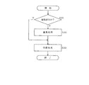
まず、プリンタ50のエミュレーション部55の編集済み情報認識部55aは、受信したPDFファイルのヘッダ部を解析し、編集済みを意味する情報を検索し、編集済みであるか否かを判断する。そして、編集済みである場合、すなわち、前記編集済みを意味する情報が見つかった場合、既に編集済みなので、エミュレーション部55は編集することなく、受信した画像データを拡大/縮小することなく印刷部54が印刷を行う。また、編集済みでない場合、すなわち、前記編集済みを意味する情報が見つからなかった場合、エミュレーション部55は印刷保証範囲に収まるように編集処理を実行し、印刷部54が印刷を行い処理を終了する。
First, the edited
次に、フローチャートについて説明する。
ステップS101 編集済みであるか否かを判断する。編集済みである場合はステップS103に進み、編集済みでない場合はステップS102に進む。
ステップS102 印刷範囲に収まるように編集処理を実行する。
ステップS103 印刷部54で印刷を行い処理を終了する。
Next, a flowchart will be described.
Step S101: It is determined whether or not the editing has been completed. If it has been edited, the process proceeds to step S103, and if it has not been edited, the process proceeds to step S102.
Step S102: Edit processing is performed so as to be within the print range.
Step S103 Printing is performed by the
このように、本実施の形態においては、印刷データ生成装置としてのMFP10が、編集済み情報を編集済み画像データに付加する仕組みを有し、プリンタ50が編集済み情報を認識する手段、及び、画像データが編集済みであると認識したときには、通常の編集処理を行わない仕組みを有する。そのため、印刷処理時間が早くなり、使い勝手が向上する。
As described above, in the present embodiment, the
なお、前記第1〜第4の実施の形態においては、印刷データ生成装置がMFPである場合について説明したが、特にこれに限ったものではなく、印刷データ生成装置がネットワークスキャナ、PCにインストールされるプリンタドライバ及びユーティリティである場合にも適用可能である。 In the first to fourth embodiments, the case where the print data generation apparatus is an MFP has been described. However, the present invention is not limited to this, and the print data generation apparatus is installed in a network scanner or a PC. The present invention can also be applied to printer drivers and utilities.
また、本発明は前記実施の形態に限定されるものではなく、本発明の趣旨に基づいて種々変形させることが可能であり、それらを本発明の範囲から排除するものではない。 The present invention is not limited to the above-described embodiment, and various modifications can be made based on the spirit of the present invention, and they are not excluded from the scope of the present invention.
10 MFP
12 オペレーションパネル
13 メモリ
14 編集部
50 プリンタ
10 MFP
12
Claims (8)
(b)前記印刷装置の印刷保証領域情報を格納する情報格納部と、該情報格納部に格納された前記印刷保証領域情報に基づいて前記画像データの編集を行う編集部とを有することを特徴とする印刷データ生成装置。 (A) A print data generation device that generates print data to be transmitted to a printing device that prints image data,
(B) An information storage unit that stores print guarantee area information of the printing apparatus, and an editing unit that edits the image data based on the print guarantee area information stored in the information storage unit. A print data generation device.
(b)前記印刷データが含む編集済みを意味する情報を認識する手段を有し、前記情報が認識されると編集処理を行わないことを特徴とする印刷装置。 (A) A printing apparatus that prints print data transmitted from the print data generation apparatus according to any one of claims 1 to 7,
(B) A printing apparatus having means for recognizing information that means that the print data includes edited information, and does not perform editing processing when the information is recognized.
Priority Applications (1)
| Application Number | Priority Date | Filing Date | Title |
|---|---|---|---|
| JP2006239711A JP4646876B2 (en) | 2005-09-08 | 2006-09-05 | Print data generator |
Applications Claiming Priority (2)
| Application Number | Priority Date | Filing Date | Title |
|---|---|---|---|
| JP2005260006 | 2005-09-08 | ||
| JP2006239711A JP4646876B2 (en) | 2005-09-08 | 2006-09-05 | Print data generator |
Publications (2)
| Publication Number | Publication Date |
|---|---|
| JP2007102766A true JP2007102766A (en) | 2007-04-19 |
| JP4646876B2 JP4646876B2 (en) | 2011-03-09 |
Family
ID=38029597
Family Applications (1)
| Application Number | Title | Priority Date | Filing Date |
|---|---|---|---|
| JP2006239711A Expired - Fee Related JP4646876B2 (en) | 2005-09-08 | 2006-09-05 | Print data generator |
Country Status (1)
| Country | Link |
|---|---|
| JP (1) | JP4646876B2 (en) |
Cited By (1)
| Publication number | Priority date | Publication date | Assignee | Title |
|---|---|---|---|---|
| JP2020160534A (en) * | 2019-03-25 | 2020-10-01 | ブラザー工業株式会社 | Creation program and transmission program |
Citations (5)
| Publication number | Priority date | Publication date | Assignee | Title |
|---|---|---|---|---|
| JPH11147345A (en) * | 1997-09-09 | 1999-06-02 | Seiko Epson Corp | Print controlling device and method thereof as well as recording medium |
| JP2002055801A (en) * | 2000-08-10 | 2002-02-20 | Canon Inc | Information processor, method for displaying printing preview and storage medium storing computer readable program |
| JP2003008814A (en) * | 2001-06-20 | 2003-01-10 | Canon Inc | Information processor, control method for the information processor, program, and storage medium |
| JP2003288181A (en) * | 2002-03-27 | 2003-10-10 | Kyocera Corp | Remote print system |
| JP2005136898A (en) * | 2003-10-31 | 2005-05-26 | Kyocera Mita Corp | Image reading apparatus and image forming system |
-
2006
- 2006-09-05 JP JP2006239711A patent/JP4646876B2/en not_active Expired - Fee Related
Patent Citations (5)
| Publication number | Priority date | Publication date | Assignee | Title |
|---|---|---|---|---|
| JPH11147345A (en) * | 1997-09-09 | 1999-06-02 | Seiko Epson Corp | Print controlling device and method thereof as well as recording medium |
| JP2002055801A (en) * | 2000-08-10 | 2002-02-20 | Canon Inc | Information processor, method for displaying printing preview and storage medium storing computer readable program |
| JP2003008814A (en) * | 2001-06-20 | 2003-01-10 | Canon Inc | Information processor, control method for the information processor, program, and storage medium |
| JP2003288181A (en) * | 2002-03-27 | 2003-10-10 | Kyocera Corp | Remote print system |
| JP2005136898A (en) * | 2003-10-31 | 2005-05-26 | Kyocera Mita Corp | Image reading apparatus and image forming system |
Cited By (2)
| Publication number | Priority date | Publication date | Assignee | Title |
|---|---|---|---|---|
| JP2020160534A (en) * | 2019-03-25 | 2020-10-01 | ブラザー工業株式会社 | Creation program and transmission program |
| JP7314558B2 (en) | 2019-03-25 | 2023-07-26 | ブラザー工業株式会社 | Creation program and transmission program |
Also Published As
| Publication number | Publication date |
|---|---|
| JP4646876B2 (en) | 2011-03-09 |
Similar Documents
| Publication | Publication Date | Title |
|---|---|---|
| US20080016449A1 (en) | Image processing apparatus, image processing method, and storage medium | |
| US8203724B2 (en) | Image forming apparatus and control method therefor, as well as program for implementing the control method | |
| US20150317112A1 (en) | Copying apparatus, copying system, control method thereof, and control program thereof | |
| US8477344B2 (en) | Network system, method, and computer readable medium for image processing apparatus with transmission and storage capability of generated data to specific storage location in data server | |
| JP2007034847A (en) | Retrieval apparatus and retrieval method | |
| JP2005539328A (en) | Information retrieval launched from scanned image media | |
| KR100956186B1 (en) | Workflow support apparatus, method of controlling the same, and workflow support system | |
| JP5058904B2 (en) | Image processing apparatus, image processing method, and program thereof | |
| JP5328327B2 (en) | Workflow system, image processing apparatus, and control method for image processing apparatus | |
| JP2006341614A (en) | Image forming device and image forming method | |
| JP4355732B2 (en) | Control device, program, computer-readable recording medium, image device control system, and control method | |
| JP4908773B2 (en) | Image processing apparatus, control method therefor, program, and storage medium | |
| US20060268334A1 (en) | Data processing apparatus connectable to network, and control method therefor | |
| US8502993B2 (en) | Print data generating apparatus | |
| US8656033B2 (en) | Information processing apparatus and data processing method | |
| JP2005119095A (en) | Image processor, printer, program, and recording medium | |
| JP2006150791A (en) | Imaging device | |
| US8482746B2 (en) | Multifunction image processing apparatus and method of controlling the multifunction image processing apparatus | |
| US8064652B2 (en) | Image processing apparatus and control method for printing image sized according to determined face area | |
| US20080131182A1 (en) | Print instructing apparatus, print system and computer-readable medium | |
| JP4347159B2 (en) | Image forming apparatus, print mode setting method, and printer driver | |
| JP4646876B2 (en) | Print data generator | |
| JP2005161556A (en) | Image forming apparatus | |
| JP5173566B2 (en) | Image processing apparatus, control method therefor, and program | |
| JP2013098604A (en) | Image processing apparatus, image processing method and program |
Legal Events
| Date | Code | Title | Description |
|---|---|---|---|
| A621 | Written request for application examination |
Free format text: JAPANESE INTERMEDIATE CODE: A621 Effective date: 20080715 |
|
| A977 | Report on retrieval |
Free format text: JAPANESE INTERMEDIATE CODE: A971007 Effective date: 20100709 |
|
| A131 | Notification of reasons for refusal |
Free format text: JAPANESE INTERMEDIATE CODE: A131 Effective date: 20100720 |
|
| A521 | Written amendment |
Free format text: JAPANESE INTERMEDIATE CODE: A523 Effective date: 20100915 |
|
| TRDD | Decision of grant or rejection written | ||
| A01 | Written decision to grant a patent or to grant a registration (utility model) |
Free format text: JAPANESE INTERMEDIATE CODE: A01 Effective date: 20101207 |
|
| A01 | Written decision to grant a patent or to grant a registration (utility model) |
Free format text: JAPANESE INTERMEDIATE CODE: A01 |
|
| A61 | First payment of annual fees (during grant procedure) |
Free format text: JAPANESE INTERMEDIATE CODE: A61 Effective date: 20101207 |
|
| FPAY | Renewal fee payment (event date is renewal date of database) |
Free format text: PAYMENT UNTIL: 20131217 Year of fee payment: 3 |
|
| R150 | Certificate of patent or registration of utility model |
Free format text: JAPANESE INTERMEDIATE CODE: R150 |
|
| LAPS | Cancellation because of no payment of annual fees |