JP2007081750A - Image forming apparatus, its method, and program - Google Patents
Image forming apparatus, its method, and program Download PDFInfo
- Publication number
- JP2007081750A JP2007081750A JP2005266039A JP2005266039A JP2007081750A JP 2007081750 A JP2007081750 A JP 2007081750A JP 2005266039 A JP2005266039 A JP 2005266039A JP 2005266039 A JP2005266039 A JP 2005266039A JP 2007081750 A JP2007081750 A JP 2007081750A
- Authority
- JP
- Japan
- Prior art keywords
- image
- gradation
- density
- image forming
- pattern
- Prior art date
- Legal status (The legal status is an assumption and is not a legal conclusion. Google has not performed a legal analysis and makes no representation as to the accuracy of the status listed.)
- Pending
Links
Images


Abstract
Description
本発明は、画像形成装置及びその方法、並びにプログラムに関し、文書の背景に偽造抑止地紋を印刷する画像形成装置及びその方法、並びにプログラムに関する。 The present invention relates to an image forming apparatus, a method thereof, and a program, and more particularly to an image forming apparatus, a method thereof, and a program for printing a forgery-suppressing tint block on the background of a document.
領収書、証券、証明書等の重要文書には、簡単に複写されることを防止するために、複写すると「複写物」等の文字や画像(以下、「潜像」という。)が浮かび上がる偽造抑止地紋が背景に印刷されているものがある。 To prevent easy copying of important documents such as receipts, securities, certificates, etc., characters and images (hereinafter referred to as “latent images”) such as “copies” appear when copied. Some have anti-counterfeiting background patterns printed on the background.
この偽造抑止地紋は、複写後にドットが残る領域(以下、「潜像部」という。)と、複写後にドットが消える領域(以下、「背景部」という。)のほぼ同じ濃度の2つの領域から構成されている。潜像部及び背景部はほぼ同じ濃度であるので、視覚的には、文字や画像である潜像が隠れていることは分からない。 The forgery-inhibited tint block is composed of two areas having substantially the same density, an area where dots remain after copying (hereinafter referred to as “latent image portion”) and an area where dots disappear after copying (hereinafter referred to as “background portion”). It is configured. Since the latent image portion and the background portion have substantially the same density, it is visually unknown that the latent image that is a character or an image is hidden.
例えば、潜像部は各々のドットが集中した固まりのドットで構成し、背景部は各々のドットが分散したドットで構成することで、このような濃度がほぼ同じでそれぞれ特性が異なる二つの領域を作り出すことができる。 For example, the latent image part is composed of a clustered dot in which each dot is concentrated, and the background part is composed of dots in which each dot is dispersed. Can produce.
図22に示すように、潜像部2201は複数のドットが集中して配置されており、背景部2202は複数のドットが分散して配置されている。
As shown in FIG. 22, the
一般に、複写機には、複写原稿の入力解像度や出力解像度に依存して、画像再現能力の限界が存在する。従って、複写機の画像再現能力の限界を超えた孤立した微小なドットを含む原稿を複写すると、微小なドットを再現することができない。偽造抑止地紋を含む原稿では、背景部を構成する分散したドットは複写により再現できず、潜像部を構成する集中したドットは複写により再現できるので、複写により潜像が浮かび上がる。 Generally, a copying machine has a limited image reproduction capability depending on the input resolution and output resolution of a copy document. Therefore, if a document including isolated minute dots exceeding the limit of the image reproduction capability of the copying machine is copied, the minute dots cannot be reproduced. In a manuscript including a forgery-inhibited tint block, dispersed dots constituting the background portion cannot be reproduced by copying, and concentrated dots constituting the latent image portion can be reproduced by copying, so that the latent image emerges by copying.
従来は、印刷用紙メーカーが、予め専用紙に潜像を含む地紋を印刷し、複写防止用紙として販売していた。近年、偽造抑止地紋を作成し、レーザプリンタでその偽造抑止地紋が背景に配置された文書を出力する技術(以下、「プリンタによるオンデマンド地紋出力法」という。)が実現されている(例えば、特許文献1参照)。 Conventionally, printing paper manufacturers have previously printed a copy-forgery-inhibited pattern including a latent image on dedicated paper and sold it as copy-proof paper. In recent years, a technique for creating a forgery-inhibited background pattern and outputting a document in which the forgery-inhibited background pattern is arranged in the background by a laser printer (hereinafter referred to as “on-demand background pattern output method by a printer”) has been realized (for example, Patent Document 1).
このプリンタによるオンデマンド地紋出力法では、普通紙を用いて背景に偽造抑止地紋が配置された文書を印刷できるので、必要な時に必要な枚数だけ背景に偽造抑止地紋が配置された文書を印刷することができるので、コストを大幅に削減することができる。また、利用者が、任意の潜像を含む地紋画像を生成することができる。 With this on-demand copy-forgery-inhibited pattern output method using a printer, it is possible to print a document with forgery-suppressed copy-forgery-inhibited patterns placed on the background using plain paper. The cost can be greatly reduced. In addition, the user can generate a tint block image including an arbitrary latent image.
また、プリンタの階調を補正するために、感光体や中間体上の階調パッチを読み込み、γ−LUTにフィードバックする方法や、記録紙に階調パターンを出力し、出力物をリーダーで読み込ませ階調特性を補正する方法が知られている(例えば、特許文献2参照)。
しかしながら、上述したプリンタによるオンデマンド地紋出力法においては、プリンタエンジン特性、温度や湿度等の印刷環境、出力する用紙等の状態に依存して、潜像部の濃度と背景部の濃度が変動する。従って、地紋画像の潜像部と背景部の印刷濃度がほぼ等しくなり、かつ複写後に潜像部が浮かび上がるように、地紋画像の潜像部と背景部の濃度を適切に調整する必要がある。 However, in the above-described on-demand background pattern output method using a printer, the density of the latent image portion and the density of the background portion vary depending on the printer engine characteristics, the printing environment such as temperature and humidity, and the state of the output paper. . Accordingly, it is necessary to appropriately adjust the density of the latent image portion and the background portion of the copy-forgery-inhibited pattern image so that the print density of the latent image portion and the background portion of the copy-forgery-inhibited pattern image is substantially equal and the latent image portion emerges after copying. .
本明細書では、地紋画像を生成する際に地紋画像の背景部と潜像部の印刷濃度を決定するパラメータを「地紋濃度パラメータ」と称す。この地紋濃度パラメータを探す方法としては、文書と地紋画像を合成する前に、試し刷りを行う。試し刷りした印刷物から、潜像部と背景部の濃度がほぼ等しくなり、複写機で複写した後に潜像が浮かび上がる地紋画像を視覚的に探し、その地紋画像を生成する際に用いた地紋濃度パラメータを最適な地紋パラメータとして決定する方法が一般的である。その後、決定した最適な地紋濃度パラメータに基づいて地紋画像を生成し、複写を抑止したい文書と地紋画像を合成して印刷出力する。 In this specification, a parameter that determines the print density of the background portion and the latent image portion of the copy-forgery-inhibited pattern image when generating the copy-forgery-inhibited pattern image is referred to as a “background pattern density parameter”. As a method of searching for the tint block density parameter, trial printing is performed before the document and the tint block image are synthesized. The density of the background pattern used to generate a copy-forgery-inhibited pattern image by visually searching for a copy-forgery-inhibited pattern image in which the latent image area and background area have almost the same density from the test print, and the latent image emerges after copying with a copier. A method for determining a parameter as an optimum tint block parameter is generally used. Thereafter, a copy-forgery-inhibited pattern image is generated based on the determined optimum copy-forgery-inhibited pattern density parameter.
しかしながら、上記試し刷りをする方法では、プリンタエンジン特性等を考慮に入れて、薄い濃度から濃い濃度まで比較的広い範囲の多数の地紋濃度パラメータの組み合わせで試し刷りし、最適な地紋濃度パラメータを決定しなければならない。 However, in the test printing method described above, taking into account printer engine characteristics and the like, trial printing is performed with a combination of a large number of background pattern density parameters in a relatively wide range from a light density to a dark density, and an optimum background pattern density parameter is determined. Must.
また、特許文献2参照の階調特性を補正する方法により、得られた階調特性データにより、地紋画像の出力値を決定することも可能だが、プリンタの階調性はプリント枚数や放置時間により変化するため、常に適正な地紋画像が得られるとは限らない。
In addition, the output value of the tint block image can be determined from the obtained gradation characteristic data by the method of correcting the gradation characteristic as described in
本発明の目的は、潜像部と背景部とで視覚的な濃度差が少ない地紋画像を出力することができる画像形成装置及びその方法、並びにプログラムを提供することにある。 An object of the present invention is to provide an image forming apparatus and method, and a program capable of outputting a tint block image having a small visual density difference between a latent image portion and a background portion.
上述の目的を達成するために、請求項1記載の画像形成装置は、潜像部と背景部とを含む地紋画像を印刷する画像形成装置において、前記潜像部の濃度及び前記背景部の濃度がそれぞれ所定の濃度になるように、前記潜像部用の階調及び前記背景部用の階調の少なくとも1つを補正する補正手段と、前記補正された階調に基づいて前記潜像部用の画像信号及び前記背景部用の画像信号をそれぞれ出力する出力手段と、前記各画像信号に基づいて前記地紋画像を印刷する印刷手段とを備えることを特徴とする。
In order to achieve the above object, the image forming apparatus according to
請求項8記載の画像形成装置は、通常画像を形成する通常画像モードと、潜像部と背景部とを含む地紋画像を形成する地紋画像モードとの2つの画像形成モードを有する画像形成装置において、像担持体又は記録紙上に第1の階調パターンを形成する階調パターン形成手段と、前記像担持体又は前記記録紙上に形成された第1の階調パターンの濃度を読み込む読み込み手段と、前記読み込んだ濃度基づいて画像形成条件を変更する変更手段と、前記画像形成条件に基づいて画像を形成する画像形成手段とを備え、前記階調パターン形成手段は、地紋画像モードが選択された場合、前記像担持体又は記録紙上に第2の階調パターンを形成することを特徴とする。
9. The image forming apparatus according to
請求項10記載の画像形成方法は、潜像部と背景部とを含む地紋画像を印刷する画像形成方法において、前記潜像部の濃度及び前記背景部の濃度がそれぞれ所定の濃度になるように、前記潜像部用の階調及び前記背景部用の階調の少なくとも1つを補正する補正ステップと、前記補正された階調に基づいて前記潜像部用の画像信号及び前記背景部用の画像信号をそれぞれ出力する出力ステップと、前記各画像信号に基づいて前記地紋画像を印刷する印刷ステップとを備えることを特徴とする。
11. The image forming method according to
請求項17記載の画像形成方法は、通常画像を形成する通常画像モードと、潜像部と背景部とを含む地紋画像を形成する地紋画像モードとの2つの画像形成モードを有する画像形成方法において、像担持体又は記録紙上に第1の階調パターンを形成する階調パターン形成ステップと、前記像担持体又は前記記録紙上に形成された第1の階調パターンの濃度を読み込む読み込みステップと、前記読み込んだ濃度基づいて画像形成条件を変更する変更ステップと、前記画像形成条件に基づいて画像を形成する画像形成ステップとを備え、前記階調パターン形成ステップは、地紋画像モードが選択された場合、前記像担持体又は記録紙上に第2の階調パターンを形成することを特徴とする。
The image forming method according to
請求項19記載のプログラムは、潜像部と背景部とを含む地紋画像を印刷する画像形成方法で実行されるプログラムにおいて、前記潜像部の濃度及び前記背景部の濃度がそれぞれ所定の濃度になるように、前記潜像部用の階調及び前記背景部用の階調の少なくとも1つを補正する補正モジュールと、前記補正された階調に基づいて前記潜像部用の画像信号及び前記背景部用の画像信号をそれぞれ出力する出力モジュールと、前記各画像信号に基づいて前記地紋画像を印刷する印刷モジュールとを備えることを特徴とする。
The program according to
本発明によれば、潜像部の濃度及び背景部の濃度がそれぞれ所定の濃度になるように、潜像部用の階調及び背景部用の階調の少なくとも1つを補正するので、潜像部と背景部とで視覚的な濃度差が少ない地紋画像を出力することができる。 According to the present invention, at least one of the gradation for the latent image portion and the gradation for the background portion is corrected so that the density of the latent image portion and the density of the background portion become predetermined densities. A tint block image with a small visual density difference between the image portion and the background portion can be output.
以下、本発明の実施の形態を図面を参照しながら詳述する。 Hereinafter, embodiments of the present invention will be described in detail with reference to the drawings.
[第1の実施の形態]
図1は、本発明の第1の実施の形態に係る画像形成装置の内部構成を概略的に示す図である。
[First Embodiment]
FIG. 1 is a diagram schematically showing an internal configuration of an image forming apparatus according to a first embodiment of the present invention.
図1において、画像形成装置100は、イメージスキャナ部18、A/Dコンバータ21、制御部22、レーザドライバ24、半導体レーザ20、ポリゴンミラー28、及びミラー17eを備える。
1, the
また、画像形成装置は、感光体1、スコロトロン1次帯電器2、現像装置4、表面電位センサ41、転写ローラ8、クリーニング装置13、前露光ランプ30、定着装置12、帯電制御部50、及びパッチ検出部51を備える。
The image forming apparatus includes a
イメージスキャナ部18は、原稿ガラス台14、照明ランプ16、ミラー17a,17b,17c、レンズ17d、及び光電変換素子19を備える。
The
照明ランプ16は、原稿ガラス台14上に載置されている原稿15を走査する。ミラー17a,17b,17cは、照明ランプ16により走査された原稿15からの反射光をレンズ17dに導く。レンズ17dは、原稿15からの反射光を光電変換素子19上に結像させる。光電変換素子19は、結像された原稿15からの反射光を電気信号に変換してA/Dコンバータ21に出力する。
The
A/Dコンバータ21は、光電変換素子19により出力された電気信号をデジタル化する。制御部22は、A/Dコンバータ21によりデジタル化された電気信号をその画像濃度に比例して0(00hex)から255(FFhex)の256階調の画像信号に変換してレーザドライバ24に出力する。
The A /
感光体1は、円筒状の導電基体上に光導電層を設けたもので、矢印方向に回転自在に軸支されている。スコロトロン1次帯電器2は、感光体1の表面を帯電させる。
The
レーザドライバ24は、制御部22により出力された画像信号に応じて半導体レーザ20の発光を変調する。半導体レーザ20は、画像信号に応じて変調されたレーザ光をポリゴンミラー28、ミラー17eを介して感光体1に照射し、スコロトロン1次帯電器2により帯電された感光体1上に静電潜像を形成する。
The
現像装置4は、感光体1上に形成された静電潜像にトナーを付着させ、感光体1上にトナー像を形成する。転写ローラ8は、感光体1上に形成されたトナー像を記録紙P上に転写する。
The developing
クリーニング装置13は、トナー像を転写した後の感光体1上の残留トナーを除去する。前露光ランプ30は、感光体1の残留電荷を除去する。
The
トナー像が転写された記録紙Pは、感光体1から分離された後に定着装置12に搬送される。定着装置12は、この搬送された記録紙Pの表面にトナー像を定着させ、画像が形成された記録紙Pを画像形成装置の外部に排出する。
The recording paper P onto which the toner image has been transferred is separated from the
感光体1には製造上のばらつきにより帯電能の良いもの、悪いものが存在する。更に、長期の使用や画像形成装置の使用環境の変化によっても、スコロトロン1次帯電器2の放電特性が変化すること等により、感光体1の帯電能は変化する。
Some
感光体1の帯電能のばらつきを吸収するために、表面電位センサ41は、現像位置4近傍での感光体1の表面電位を検知して帯電制御部50に信号を出力する。帯電制御部50は表面電位センサ41により出力された信号に基づいて、感光体1の表面電位を所望の電位に保つように1次帯電器2のグリッドに印加する電圧を変化させる。
The surface
パッチ検出部51は、感光体1上に基準となるパッチを形成するためのLEDと、感光体1上に形成されたパッチの反射光量を読み取る濃度センサとを備える。この読み取った感光体1上のパッチの反射光量により、感光体1上のトナー付着量を演算し、その結果から画像制御条件(γ−LUT、帯電電位、レーザパワー等)を制御する。
The
本実施の形態では、画像形成装置100の現像方式として一成分ジャンピング現像方式を採用するものとするが、これに限られるものではない。
In this embodiment, the one-component jumping development method is adopted as the development method of the
画像形成装置100は、通常画像を印刷する通常モードと、地紋画像を印刷する地紋モードを有する。地紋モードでは、制御部22により生成された地紋画像、又は、制御部22が外部装置から受信した地紋画像を印刷する。
The
地紋画像は、複写後にドットが残る領域(以下、「潜像部」という。)、及び複写後にドットが消える領域(以下、「背景部」という。)のほぼ同じ濃度の2つの領域から構成されている。 The copy-forgery-inhibited pattern image is composed of two areas having substantially the same density, an area where dots remain after copying (hereinafter referred to as “latent image portion”) and an area where dots disappear after copying (hereinafter referred to as “background portion”). ing.
本実施の形態では、背景部に対応する画像は、ドット分散型ディザマトリクスを用いてドットが離散的に配置されるように設計する。また、潜像部に対応する画像は、ドット集中型ディザマトリクスを用いてドットが集中して配置されるように設計する。以下、背景部の画像生成に用いるディザマトリクスを背景ディザマトリクス、潜像部の画像生成に用いるディザマトリクスを潜像ディザマトリクスと呼ぶこととする。 In the present embodiment, the image corresponding to the background portion is designed so that dots are discretely arranged using a dot dispersion type dither matrix. The image corresponding to the latent image portion is designed so that the dots are concentrated by using a dot concentration type dither matrix. Hereinafter, the dither matrix used for generating the background image is referred to as a background dither matrix, and the dither matrix used for generating the latent image portion is referred to as a latent image dither matrix.
ディザ法は、多値の入力画像信号を一定の規則により算出された閾値と比較し、その大小関係に応じて2値画像を出力する方法である。ディザマトリクスはディザ法で入力画像信号を2値化する際の閾値が2次元的に配置された閾値マトリクスである。 The dither method is a method in which a multi-value input image signal is compared with a threshold value calculated according to a certain rule, and a binary image is output according to the magnitude relationship. The dither matrix is a threshold matrix in which thresholds for binarizing an input image signal by the dither method are two-dimensionally arranged.
入力画像信号の画素値を対応するディザマトリクスの閾値で2値化処理することにより、2値画像(閾値パターン)が得られる。ここで得られる2値画像は入力画像信号の階調がディザマトリクスの閾値未満の場合には、画素値に一方のビット(例えば0)、閾値以上の場合には他方のビット(例えば1)が割り当てられる。 A binary image (threshold pattern) is obtained by binarizing the pixel value of the input image signal with the threshold value of the corresponding dither matrix. The binary image obtained here has one bit (for example, 0) in the pixel value when the gradation of the input image signal is less than the threshold value of the dither matrix, and the other bit (for example, 1) in the case of the threshold value or more. Assigned.
以下、背景部を構成する2値画像を「背景閾値パターン」、潜像部を構成する2値画像を「潜像閾値パターン」という。 Hereinafter, the binary image constituting the background portion is referred to as “background threshold pattern”, and the binary image constituting the latent image portion is referred to as “latent image threshold pattern”.
次に、本実施の形態での潜像部と背景部におけるドットの配置方法について説明する。本実施の形態では、潜像部をドット集中型ディザマトリクス、背景部をドット分散型ディザマトリクスに基づいて生成する場合について説明する。ドット集中型ディザマトリクスとしては、例えば、図2の渦巻き型ディザマトリクスが挙げられる。 Next, a method for arranging dots in the latent image portion and the background portion in this embodiment will be described. In the present embodiment, a case will be described in which a latent image portion is generated based on a dot concentration type dither matrix and a background portion is generated based on a dot dispersion type dither matrix. An example of the dot-concentrated dither matrix is the spiral dither matrix shown in FIG.
図2は、図1の画像形成装置で使用される渦巻き型ディザマトリクスを示す図である。 FIG. 2 is a diagram showing a spiral dither matrix used in the image forming apparatus of FIG.
図2の12×12の渦巻き型ディザマトリクス600において、閾値は、渦巻き状に中心から数値が増加するように配置されている。任意の入力画像信号を12×12の渦巻き型ディザマトリクス600でディザ処理を行って生成される閾値パターンは、複数のドットが集中して配置されるように設計されている。
In the 12 × 12
渦巻き型ディザマトリクス600を用いて、入力画像信号12を閾値処理すると、図3に示す閾値パターン(ドット配置)が得られる。
When the
図3は、図2の渦巻き型ディザマトリクスを用いて画像信号を処理して得られる閾値パターンを示す図である。 FIG. 3 is a diagram showing a threshold pattern obtained by processing an image signal using the spiral dither matrix of FIG.
図3において、網掛け部分は、入力画像信号12を12×12の渦巻き型ディザマトリクス600で閾値処理して得られる閾値パターンを示している。ここで得られる閾値パターン(ドット配置)は、複数のドットが集中して配置されるパターンとなっている。
In FIG. 3, the shaded portion indicates a threshold pattern obtained by performing threshold processing on the
一方、背景部を構成するドット分散型ディザマトリクスとしては、図4に示すドット分散型ディザマトリクスを利用する。 On the other hand, the dot dispersion type dither matrix shown in FIG. 4 is used as the dot dispersion type dither matrix constituting the background portion.
図4は、図1の画像形成装置で使用されるドット分散型ディザマトリクスを示す図である。 FIG. 4 is a diagram showing a dot dispersion type dither matrix used in the image forming apparatus of FIG.
図4の12×12のドット分散ディザマトリクス800において、閾値マトリクスの各要素は相互になるべく接触しない位置に順に配置され、その閾値パターンは孤立した格子状のドット配置をとる。任意の入力画像信号を12×12のドット分散ディザマトリクス800でディザ処理を行って生成される閾値パターンは、複数のドットが分散して配置されるように設計されている。
In the 12 × 12 dot
図5は、図4のドット分散型ディザマトリクスを用いて画像信号を処理して得られる閾値パターンを示す図である。 FIG. 5 is a diagram showing threshold patterns obtained by processing image signals using the dot dispersion type dither matrix of FIG.
図5において、網掛け部分は、入力画像信号12を12×12のドット分散ディザマトリクス800で閾値処理して得られる閾値パターンを示している。ここで得られる閾値パターン(ドット配置)では、複数のドットが互いに分散して配置されている。
In FIG. 5, shaded portions indicate threshold patterns obtained by performing threshold processing on the
本実施の形態では、背景ディザマトリクスとして、ドット分散型ディザマトリクス800を用いるものとして説明するが、これに限定されるものではない。その他のドット分散型ディザマトリクス、例えば、ブルーノイズマスクを用いてもよい。
In the present embodiment, description will be made assuming that the dot dispersion
このブルーノイズマスクは、任意の階調での閾値パターンが全てブルーノイズ特性を有し、閾値パターンを形成する黒画素の分布がランダムではあるが一様性が高く、粒状性が目立ちにくい。ブルーノイズ特性とは、任意の階調に設定した場合の点の出力パターンが局所的に非周期的(locally aperiodic)、かつ等方的(isotropic)で低周波成分が少ないことを意味する。ブルーノイズマスクから得られる閾値パターンはモアレの発生を防止し、紙送りムラを目立ちにくくする等、視覚的に好ましい出力パターンが得られる長所がある。 In this blue noise mask, all threshold patterns in an arbitrary gradation have blue noise characteristics, and the distribution of black pixels forming the threshold pattern is random but highly uniform, and the graininess is not conspicuous. The blue noise characteristic means that the output pattern of points when set to an arbitrary gradation is locally aperiodic and isotropic, and has low frequency components. The threshold pattern obtained from the blue noise mask has an advantage that a visually preferable output pattern can be obtained, for example, by preventing the occurrence of moire and making paper feed unevenness inconspicuous.
また、ブルーノイズマスクでなくとも、特定又は任意の階調での閾値パターンが周期的(又は擬似周期的)、かつ非等方的で低周波成分が少ないドット分散型ディザマトリクスを用いてもよい。また閾値パターンを用いる方法以外にも、誤差拡散法を用いた背景部の構成も可能である。 In addition, a dot dispersion type dither matrix may be used that is not a blue noise mask but has a periodic (or pseudo-periodic) threshold pattern at a specific or arbitrary gradation, is anisotropic, and has low low-frequency components. . In addition to the method using the threshold pattern, it is possible to configure the background portion using the error diffusion method.
また、本実施の形態では、背景部と潜像部のディザスクリーンの大きさは同じ12×12であるとしたが、両者のスクリーンの大きさは異なっていてもよい。更に、各階調における閾値パターンは、ディザマトリクスに基づき生成するものとしたが、これに限られるものではない。階調毎に独自に背景閾値パターン、潜像閾値パターンを生成してもよい。この場合、各階調毎に画質のよい閾値パターンを集めることができるメリットもある。 In this embodiment, the size of the dither screen in the background portion and the latent image portion is the same 12 × 12. However, the sizes of the two screens may be different. Further, although the threshold pattern for each gradation is generated based on the dither matrix, the present invention is not limited to this. A background threshold pattern and a latent image threshold pattern may be independently generated for each gradation. In this case, there is also an advantage that threshold patterns having good image quality can be collected for each gradation.
潜像部と背景部とで黒画素の面積比率を同じにしておけば、理論上濃度は等しくなり、潜像部と背景部の境界は分かりづらく、地紋モードとして利用できる。しかしながら、実際には、プリンタの特性により、潜像ディザマトリクスと背景ディザマトリクスの階調特性が必ずしも同一になるとは限らない。 If the area ratio of black pixels is the same in the latent image portion and the background portion, the density is theoretically equal, and the boundary between the latent image portion and the background portion is difficult to understand and can be used as a tint block mode. However, actually, the gradation characteristics of the latent image dither matrix and the background dither matrix are not always the same due to the characteristics of the printer.
制御部22は、後述する図9の地紋印刷処理を実行して、潜像ディザマトリクスの階調特性及び背景ディザマトリクスの階調特性を求め、これに基づいて、出力する信号レベルを決定する。
The
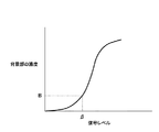
図6は、図1における制御部22によって求められる潜像ディザマトリクスの階調特性を示す図であり、図7は、図1における制御部22によって求められる背景ディザマトリクスの階調特性を示す図である。
6 is a diagram showing the tone characteristics of the latent image dither matrix obtained by the
例えば、潜像ディザマトリクスの階調特性は図6に示すような緩やかなS字カーブで、背景ディザマトリクスの階調特性は図7に示すような急峻なS字カーブで表されるとする。このような場合、背景閾値パターンと潜像閾値パターンの黒画素の面積比率をほぼ等しく設定しても、印刷時の背景部と潜像部の濃度は同一にはならない。 For example, the gradation characteristic of the latent image dither matrix is represented by a gentle S-curve as shown in FIG. 6, and the gradation characteristic of the background dither matrix is represented by a steep S-curve as shown in FIG. In such a case, the density of the background portion and the latent image portion at the time of printing is not the same even if the area ratio of the black pixels of the background threshold pattern and the latent image threshold pattern is set to be approximately equal.
また、プリンタを用いて実際に地紋画像を出力する場合、様々な原因により、必ずしも潜像部と背景部が意図した通りの濃度で出力されるとは限らない。 Further, when the copy-forgery-inhibited pattern image is actually output using a printer, the latent image portion and the background portion are not always output at the intended density due to various causes.
理由としては、プリンタのエンジン特性や閾値パターンを出力するディザマトリクスの違い、プリンタの個体差、湿度や気温等の印刷環境、エンジンの耐久性、記録紙(メディア)の違い、プリンタのインクやトナーの違い等の様々な条件に依存した濃度不安定性を挙げることができる。即ち、背景部と潜像部のディザマトリクスのそれぞれに対する最適な入力階調は、プリンタの機種、ディザマトリクス、プリンタの個体、印刷環境、記録紙、インクやトナー等に依存して異なる。 Reasons include printer engine characteristics and dither matrix output of threshold patterns, individual printer differences, printing environment such as humidity and temperature, engine durability, recording paper (media) differences, printer ink and toner Concentration instability depending on various conditions such as differences in the above can be mentioned. That is, the optimum input gradation for each of the background portion and the latent image portion dither matrix differs depending on the printer model, dither matrix, individual printer, printing environment, recording paper, ink, toner, and the like.
従って、プリンタのエンジン特性や印刷環境が異なる場合においても、印刷時にほぼ等しい濃度となる背景閾値パターン、潜像閾値パターンを得た上で地紋画像を生成する必要がある。しかしながら、印刷環境による変動を含む全ての変動要因を考慮し、最適な背景閾値パターン、潜像閾値パターンを自動的に計算することは現実的には難しい。 Therefore, even when the engine characteristics and the printing environment of the printer are different, it is necessary to generate a copy-forgery-inhibited pattern image after obtaining a background threshold pattern and a latent image threshold pattern having substantially the same density during printing. However, it is practically difficult to automatically calculate the optimum background threshold pattern and latent image threshold pattern in consideration of all the fluctuation factors including fluctuation due to the printing environment.
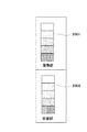
従って、地紋合成印刷装置を実行する前に、プリンタ毎に背景部と潜像部の濃度がほぼ同一になる背景閾値パターンと潜像閾値パターンを得る機能、即ち、地紋濃度キャリブレーション機能の実装が必要となる。そこで、パッチ検出部51は、図8に示す階調パッチ801,802を感光体1上に形成し、その濃度を検出する。その濃度に基づいて、制御部22で出力する信号レベルを制御する。
Therefore, before executing the tint block synthesizing printing apparatus, a function for obtaining a background threshold pattern and a latent image threshold pattern in which the density of the background portion and the latent image portion are almost the same for each printer, that is, a tint block density calibration function is implemented. Necessary. Therefore, the
図8は、図1におけるパッチ検出部51によって形成される階調パッチを示す図である。
FIG. 8 is a diagram showing the gradation patches formed by the
図8において、パッチ検出部51は、潜像部に使用するスクリーンの階調パッチ801と、背景部に使用するスクリーンの階調パッチ802と感光体1上に形成する。階調パッチ801,802の出力レベルは、それぞれ0h、10h、20h…F0h、FFhである。
In FIG. 8, the
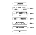
図9は、図1の画像形成装置100によって実行される地紋印刷処理の手順を示すフローチャートである。
FIG. 9 is a flowchart showing the procedure of the tint block printing process executed by the
図9において、画像形成装置100が備える不図示の操作部により、ユーザが地紋モードを選択し、プリント開始を指示する(ステップS101)。パッチ検出部51のLEDにより、感光体1上に潜像部に使用するスクリーンの階調パッチ801を形成する(ステップS102)。次に、パッチ検出部51の濃度センサにより、感光体1上に形成された階調パッチ801の濃度を測定する(ステップS103)。制御部22は、測定された階調パッチ801の濃度に基づいて、潜像部濃度Aに対応する信号レベルαを決定する(ステップS104)。
In FIG. 9, the user selects a tint block mode by using an operation unit (not shown) included in the
次に、感光体1上にパッチ検出部51のLEDにより、背景部に使用するスクリーンの階調パッチ802を形成する(ステップS105)。次に、パッチ検出部51の濃度センサにより、感光体1上に形成された階調パッチ802の濃度を測定する(ステップS106)。制御部22は、測定された階調パッチ802の濃度に基づいて、背景部濃度Bに対応する信号レベルβを決定する(ステップS107)。
Next, the
制御部22は、上記2つの信号レベルα及びβに基づいて、地紋画像を含む画像を出力し(ステップS108)、本処理を終了する。
The
ここで、濃度A,Bは、予め決定されている値である。濃度Aと濃度Bは、等しい値であるとは限らず、画像形成装置100により同じ濃度に見えるように出力される濃度である。また、濃度A,Bの値は1つではなく、地紋の濃度に応じた複数の値の組み合わせであってもよく、AとBの相関を示す関係式やテーブルであってもよい。
Here, the concentrations A and B are predetermined values. The density A and the density B are not necessarily equal values, and are densities that are output by the
第1の実施の形態によれば、地紋モードを実行する前に、地紋で使用する画像パターンのキャリブレーションを行うことにより、潜像部と背景部とで視覚的な濃度差が少ない地紋画像を出力することができる。 According to the first embodiment, by performing calibration of the image pattern used in the background pattern before executing the background pattern mode, a background pattern image with a small visual density difference between the latent image portion and the background portion is obtained. Can be output.
また、プリンタのエンジン特性、個体差等に起因する潜像部と背景部の階調再現特性の違い、印刷環境や耐久に起因する濃度変動が大きい場合がある。本実施の形態によれば、このような場合においても、潜像部と背景部の印刷濃度が近似し、複写後に背景部が消失する地紋画像を生成するために必要な、最適に潜像部と背景部の印刷濃度を決定する地紋濃度パラメータを精度良く決定することができる。 Further, there may be large density fluctuations due to differences in gradation reproduction characteristics between the latent image portion and the background portion due to printer engine characteristics, individual differences, etc., printing environment and durability. According to the present embodiment, even in such a case, the optimum latent image portion is necessary to generate a tint block image in which the print density of the latent image portion and the background portion approximates and the background portion disappears after copying. The tint block density parameter for determining the printing density of the background portion can be determined with high accuracy.
[第2の実施の形態]
第1の実施の形態では、白黒の地紋画像印刷時にキャリブレーションを行ったが、第2の実施の形態では、フルカラーの地紋画像印刷時にキャリブレーションを行う。
[Second Embodiment]
In the first embodiment, calibration is performed at the time of printing a monochrome background pattern image. In the second embodiment, calibration is performed at the time of printing a full color background pattern image.
図10は、本発明の第2の実施の形態に係る画像形成装置の内部構成を概略的に示す図である。 FIG. 10 is a diagram schematically showing an internal configuration of an image forming apparatus according to the second embodiment of the present invention.
図10において、画像形成装置200は、複数色のプロセスカートリッジPa〜Pdを備え、同一の転写材にトナー像を順次重畳して形成する。
In FIG. 10, an
また、画像形成装置200は、中間転写ベルト(ITB)128、レジストローラ132、搬送ベルト127、定着器129、パッチ検出部133、及びクリーニングブレード130を備える。
The
ITB128は、矢印X方向に走行する。このITB128は、ポリイミド、ポリカーボネート、ポリエチレンテレフタレート、ポリフッ化ビニリデン等の誘電体樹脂により形成されている。
The
不図示の給紙カセットから取り出された転写材108は、レジストローラ132を経て、ITB128の2次転写部位に供給される。
The
ITB128の上方には、4つの画像形成部Pa、Pb、Pc、Pdが直列上に配置されている。これらの画像形成部Pa、Pb、Pc、Pdは、それぞれマゼンタ、シアン、イエロー、ブラックのトナー像をITB128上に形成する。これらのトナーの極性はマイナスである。
Above the
パッチ検出部33は、ITB128上に基準となるパッチを形成するためのLEDと、ITB128上に形成されたパッチの反射光量を読み取る濃度センサとを備える。この読み取ったITB128上のパッチの反射光量により、ITB128上のトナー付着量を演算し、その結果から画像制御条件(γ−LUT、帯電電位、T/C比制御等)を制御する。
The
クリーニングブレード130は、二次転写後のITB128上の残留トナーを除去する。二次転写された記録紙108は、搬送ベルト127により定着器129に搬送される。一対の熱ローラーからなる定着器129は、この搬送された記録紙108の表面にトナーを定着させ、画像が形成された記録紙108を画像形成装置200の外部に排出する。
The
プロセスカートリッジPa、Pb、Pc、Pdの構成は、基本的に同じであり、以下、プロセスカートリッジPとしてその構成を説明する。 The configuration of the process cartridges Pa, Pb, Pc, and Pd is basically the same. Hereinafter, the configuration of the process cartridge P will be described.
図11は、図10におけるプロセスカートリッジPの内部構成を概略的に示す図である。 FIG. 11 is a diagram schematically showing an internal configuration of the process cartridge P in FIG.
図11において、プロセスカートリッジPは、露光装置120、感光体121、一次帯電器122、現像装置123、転写ローラ124、及びクリーナ125を備える。
In FIG. 11, the process cartridge P includes an
感光体121は、矢印R2方向に回転自在に軸支されている。一次帯電器122は、感光体121の表面を帯電させる。
The
露光装置120は、例えばLED、レーザ等により構成され、不図示の制御部により出力された画像信号に応じて一次帯電器122により帯電された感光体121を露光して感光体121上に静電潜像を形成する。
The
現像装置123の現像スリーブ123aは、感光体121上に形成された静電潜像にトナーを付着させ、感光体121上にトナー像を形成する。転写ローラ124は、感光体121上に形成されたトナー像をITB128に静電的に転写する。このトナー像は、ITB128に担持されて矢印X方向に搬送される。
The developing
クリーナ125は、クリーニングブレード125a、及び廃トナー搬送スクリュー125bを備える。クリーニングブレード125aは、トナー像を転写した後の感光体121上の残留トナーを除去する。廃トナー搬送スクリュー125bは、クリーニングブレード125aにより除去した残留トナーを不図示の廃トナー容器に送る。プロセスカートリッジPのプロセススピードは100mm/sである。
The cleaner 125 includes a
図12は、図10におけるパッチ検出部133によって形成される階調パッチを示す図である。
FIG. 12 is a diagram showing the gradation patches formed by the
図12において、パッチ検出部133は、潜像部に使用するスクリーンの階調パッチ1201と、背景部に使用するスクリーンの階調パッチ1202とをITB128上に形成する。階調パッチ1201,1202の出力レベルは、それぞれ0h、10h、20h…F0h、FFhである。階調パッチ1201,1202は、それぞれY、M、C、Kの4色の階調パッチを含む。
In FIG. 12, the
図13は、図10の画像形成装置200によって実行される地紋印刷処理の手順を示すフローチャートである。
FIG. 13 is a flowchart showing the procedure of the tint block printing process executed by the
図13において、画像形成装置200が備える不図示の操作部により、ユーザが地紋モードを選択し、プリント開始を指示する(ステップS1301)。パッチ検出部133のLEDにより、ITB128上に潜像部に使用するスクリーンの階調パッチ1401を全色(Y,M,C,K)形成する(ステップS1302)。次に、パッチ検出部133の濃度センサにより、ITB128上に形成された階調パッチ1401の濃度を測定する(ステップS1303)。画像形成装置の制御部は、測定された階調パッチ1401の濃度に基づいて、潜像部濃度Aに対応する信号レベルαをY,M,C,Kの各色毎に決定する(ステップS1304)。
In FIG. 13, the user selects a tint block mode by an operation unit (not shown) included in the
次に、パッチ検出部133のLEDにより、ITB128上に背景部に使用するスクリーンの階調パッチ1402を全色(Y,M,C,K)形成する(ステップS1305)。次に、パッチ検出部133の濃度センサにより、ITB128上に形成された階調パッチ1402の濃度を測定する(ステップS1306)。画像形成装置の制御部は、測定された階調パッチ1402の濃度に基づいて、背景部濃度Bに対応する信号レベルβをY,M,C,Kの各色毎に決定する(ステップS1307)。
Next, all the colors (Y, M, C, K) of the screen gradation patches 1402 used for the background portion are formed on the
画像形成装置の制御部は、上記各色毎の2つの信号レベルα及びβに基づいて、地紋画像を含む画像を出力し(ステップS1308)、本処理を終了する。 The control unit of the image forming apparatus outputs an image including a copy-forgery-inhibited pattern image based on the two signal levels α and β for each color (step S1308), and ends the process.
第2の実施の形態によれば、地紋モードを実行する前に、地紋で使用する画像パターンのキャリブレーションを行うことにより、潜像部と背景部とで視覚的な濃度差が少ない地紋画像を出力することができる。 According to the second embodiment, by executing calibration of the image pattern used in the background pattern before executing the background pattern mode, a background pattern image with a small visual density difference between the latent image portion and the background portion is obtained. Can be output.
また、プリンタのエンジン特性、個体差等に起因する潜像部と背景部の階調再現特性の違い、印刷環境や耐久に起因する濃度変動が大きい場合がある。本実施の形態によれば、このような場合においても、潜像部と背景部の印刷濃度が近似し、複写後に背景部が消失する地紋画像を生成するために必要な、最適に潜像部と背景部の印刷濃度を決定する地紋濃度パラメータを精度良く決定することができる。 Further, there may be large density fluctuations due to differences in gradation reproduction characteristics between the latent image portion and the background portion due to printer engine characteristics, individual differences, etc., printing environment and durability. According to the present embodiment, even in such a case, the optimum latent image portion is necessary to generate a tint block image in which the print density of the latent image portion and the background portion approximates and the background portion disappears after copying. The tint block density parameter for determining the printing density of the background portion can be determined with high accuracy.
本実施の形態では、ITB128上にパッチを形成してその濃度を読み込み、信号レベルと濃度の関係を求めたが、公知の階調パッチを記録紙上の出力し、出力された記録紙をリーダーで読み込ませて、出力レベルと濃度との関係を求めることもできる。この場合、二次転写及び定着の影響も考慮できるので、地紋画像の潜像部と背景部との濃度の差をより縮めることができる。
In this embodiment, a patch is formed on the
[第3の実施の形態]
第2の実施の形態では、Y,M,C,Kの全色についてキャリブレーションを行ったが、第3の実施の形態では、特定の色のみについてキャリブレーションを行う。
[Third Embodiment]
In the second embodiment, the calibration is performed for all the colors Y, M, C, and K. In the third embodiment, the calibration is performed only for a specific color.
地紋に使用する画像の色がBk等に決定されている場合や、ユーザが地紋の色を指定した場合には、第1の実施の形態と同様に指定された色のみを濃度キャリブレーションすることにより、キャリブレーション時間を短縮することができる。 When the color of the image used for the background pattern is determined to be Bk or the like, or when the user specifies the color of the background pattern, density calibration is performed only for the specified color as in the first embodiment. Thus, the calibration time can be shortened.
第3の実施の形態における画像形成装置の構成は、図10の第2の実施の形態における画像形成装置の構成と同じである。 The configuration of the image forming apparatus in the third embodiment is the same as the configuration of the image forming apparatus in the second embodiment of FIG.
図14は、本発明の第3の実施の形態における階調パッチを示す図である。 FIG. 14 is a diagram showing a gradation patch according to the third embodiment of the present invention.
図14において、パッチ検出部133は、指定された色(ここではCyan)の潜像部に使用するスクリーンの階調パッチ1601と、指定された色(ここではCyan)の背景部に使用するスクリーンの階調パッチ1602とをITB128上に形成する。階調パッチ1601,1602の出力レベルは、それぞれ0h、10h、20h…F0h、FFhである。
In FIG. 14, the
図15は、第3の実施の形態における地紋印刷処理の手順を示すフローチャートである。 FIG. 15 is a flowchart illustrating the procedure of the tint block printing process according to the third embodiment.
図15において、画像形成装置200が備える不図示の操作部により、ユーザが地紋の色を指定し、地紋モードを選択し、プリント開始を指示する(ステップS1501)。パッチ検出部133のLEDにより、ITB128上に指定された色(Cyan)の潜像部に使用するスクリーンの階調パッチ1601を形成する(ステップS1502)。次に、パッチ検出部133の濃度センサにより、ITB128上に形成された階調パッチ1601の濃度を測定する(ステップS1503)。画像形成装置の制御部は、測定された階調パッチ1601の濃度に基づいて、指定された色(Cyan)の潜像部濃度Aに対応する信号レベルαを決定する(ステップS1504)。
In FIG. 15, the user designates a tint block color, selects a tint block mode, and instructs to start printing using an operation unit (not shown) included in the image forming apparatus 200 (step S <b> 1501). The LED of the
次に、パッチ検出部133のLEDにより、ITB128上に指定された色(Cyan)の背景部に使用するスクリーンの階調パッチ1602を形成する(ステップS1505)。次に、パッチ検出部133の濃度センサにより、ITB128上に形成された階調パッチ1602の濃度を測定する(ステップS1506)。画像形成装置の制御部は、測定された階調パッチ1602の濃度に基づいて、指定された色(Cyan)の背景部濃度Bに対応する信号レベルβを決定する(ステップS1507)。
Next, the
画像形成装置の制御部は、上記2つの信号レベルα及びβに基づいて、地紋画像を含む画像を出力し(ステップS1508)、本処理を終了する。 Based on the two signal levels α and β, the control unit of the image forming apparatus outputs an image including the copy-forgery-inhibited pattern image (step S1508), and the process is terminated.
第3の実施の形態によれば、地紋モードを実行する前に、地紋で使用する画像パターンのキャリブレーションを行うことにより、潜像部と背景部とで視覚的な濃度差が少ない地紋画像を出力することができる。 According to the third embodiment, by executing calibration of the image pattern used in the background pattern before executing the background pattern mode, a background pattern image with a small visual density difference between the latent image portion and the background portion is obtained. Can be output.
また、プリンタのエンジン特性、個体差等に起因する潜像部と背景部の階調再現特性の違い、印刷環境や耐久に起因する濃度変動が大きい場合がある。本実施の形態によれば、このような場合においても、潜像部と背景部の印刷濃度が近似し、複写後に背景部が消失する地紋画像を生成するために必要な、最適に潜像部と背景部の印刷濃度を決定する地紋濃度パラメータを精度良く決定することができる。 Further, there may be large density fluctuations due to differences in gradation reproduction characteristics between the latent image portion and the background portion due to printer engine characteristics, individual differences, etc., printing environment and durability. According to the present embodiment, even in such a case, the optimum latent image portion is necessary to generate a tint block image in which the print density of the latent image portion and the background portion approximates and the background portion disappears after copying. The tint block density parameter for determining the printing density of the background portion can be determined with high accuracy.
更に、地紋に使用する画像の色のみを濃度キャリブレーションすることにより、キャリブレーションに要する時間を短縮することができる。 Furthermore, by performing density calibration only on the color of the image used for the background pattern, the time required for calibration can be shortened.
[第4の実施の形態]
第1〜第3の実施の形態では、潜像部及び背景部の両方についてキャリブレーションを行ったが、第4の実施の形態では、潜像部及び背景部の階調特性が不安定な高線数の方のみについてキャリブレーションを行う。本体構成は第1の実施の形態と同様である。
[Fourth Embodiment]
In the first to third embodiments, both the latent image portion and the background portion are calibrated. However, in the fourth embodiment, the latent image portion and the background portion have unstable gradation characteristics. Perform calibration only for the number of lines. The main body configuration is the same as that of the first embodiment.
電子写真方式のプリンタは、一般的に解像度(線数)が低くなればなるほど、画像は安定する。従って、潜像部は低線数であるので、潜像部の画像は安定しており、階調特性はあまり変化しない。そこで、本実施の形態では階調特性が不安定な高線数の背景部のみについてキャリブレーションを行うことにより、キャリブレーション時間を短縮することができる。 In an electrophotographic printer, generally, the lower the resolution (number of lines), the more stable the image. Therefore, since the latent image portion has a low number of lines, the image of the latent image portion is stable and the gradation characteristics do not change much. Therefore, in this embodiment, the calibration time can be shortened by performing calibration only for the background portion having a high number of lines with unstable gradation characteristics.
第4の実施の形態における画像形成装置の構成は、図10の第2の実施の形態における画像形成装置の構成と同じである。 The configuration of the image forming apparatus in the fourth embodiment is the same as the configuration of the image forming apparatus in the second embodiment of FIG.
図16は、本発明の第4の実施の形態における階調パッチを示す図である。 FIG. 16 is a diagram showing a gradation patch according to the fourth embodiment of the present invention.
図16において、パッチ検出部133は、指定された色(ここではCyan)の背景部に使用するスクリーンの階調パッチ1801をITB128上に形成する。階調パッチ1801の出力レベルは、0h、10h、20h…F0h、FFhである。
In FIG. 16, the
図17は、第4の実施の形態における地紋印刷処理の手順を示すフローチャートである。 FIG. 17 is a flowchart illustrating the procedure of the tint block printing process according to the fourth embodiment.
図17において、画像形成装置200が備える不図示の操作部により、ユーザが地紋の色を指定し、地紋モードを選択し、プリント開始を指示する(ステップS1701)。パッチ検出部133のLEDにより、ITB128上に指定された色(Cyan)の背景部に使用するスクリーンの階調パッチ1801を形成する(ステップS1702)。次に、パッチ検出部133の濃度センサにより、ITB128上に形成された階調パッチ1801の濃度を測定する(ステップS1703)。画像形成装置の制御部は、測定された階調パッチ1801の濃度に基づいて、指定された色(Cyan)の背景部濃度Bに対応する信号レベルβを決定する(ステップS1704)。
In FIG. 17, the user designates the tint block color, selects the tint block mode, and instructs the start of printing using an operation unit (not shown) included in the image forming apparatus 200 (step S1701). The
画像形成装置の制御部は、上記信号レベルβに基づいて、地紋画像を含む画像を出力し(ステップS1705)、本処理を終了する。 Based on the signal level β, the control unit of the image forming apparatus outputs an image including the copy-forgery-inhibited pattern image (step S1705), and ends the process.
第4の実施の形態によれば、地紋モードを実行する前に、地紋で使用する画像パターンのキャリブレーションを行うことにより、潜像部と背景部とで視覚的な濃度差が少ない地紋画像を出力することができる。 According to the fourth embodiment, by executing calibration of the image pattern used in the background pattern before executing the background pattern mode, a background pattern image with a small visual density difference between the latent image portion and the background portion is obtained. Can be output.
また、潜像部及び背景部の階調特性が不安定な高線数の方のみについてキャリブレーションを行うことで、キャリブレーションに要する時間を一層短縮することができる。 Further, by performing calibration only for the higher number of lines where the gradation characteristics of the latent image portion and the background portion are unstable, the time required for calibration can be further shortened.
なお、潜像部の出力値αについては、予め決定された値でもよく、過去に潜像部の自動キャリブレーションを実行していれば、その時に決定された濃度Aに対応する信号レベルαを使用してもよい。 Note that the output value α of the latent image portion may be a predetermined value. If automatic calibration of the latent image portion has been executed in the past, the signal level α corresponding to the density A determined at that time is set. May be used.
本実施の形態では、潜像部に低線数、背景部に高線数を使用したので、背景部のみを実行したが、潜像部に高線数、背景部に低整数を用いた逆の場合には高線数の潜像部だけを自動キャリブレーションを実行すれば同様の効果が得られる。 In this embodiment, since the low number of lines is used for the latent image portion and the high number of lines is used for the background portion, only the background portion is executed. However, the reverse operation is performed using the high line number for the latent image portion and the low integer for the background portion. In this case, the same effect can be obtained by executing automatic calibration only for the latent image portion having a high number of lines.
[第5の実施の形態]
第1〜第3の実施の形態では、潜像部及び背景部の両方についてキャリブレーションを行ったが、第5の実施の形態では、高線数側の所定の信号レベルの画像信号を出力し、その濃度に合う低線数側の信号レベルβを設定する。
[Fifth Embodiment]
In the first to third embodiments, both the latent image portion and the background portion are calibrated, but in the fifth embodiment, an image signal having a predetermined signal level on the high line number side is output. The signal level β on the low line number side that matches the density is set.
電子写真方式の場合、高線数になればなるほど階調特性が非線形化するため、高線数の信号レベルβを正確に決定するためには、パッチの階調数を多くとる必要がある。そのため、高線数側の所定の信号レベルの画像信号を出力し、その濃度に合う低線数側の信号レベルβを設定することにより、少ないパッチの階調数で正確に階調制御を行うことができる。また、キャリブレーションに要する時間を一層短縮することができる。 In the case of the electrophotographic system, the gradation characteristic becomes nonlinear as the number of lines increases, so that it is necessary to increase the number of gradations of the patch in order to accurately determine the signal level β of the high number of lines. Therefore, by outputting an image signal having a predetermined signal level on the high line number side and setting a signal level β on the low line number side that matches the density, gradation control is accurately performed with a small number of gradations of patches. be able to. In addition, the time required for calibration can be further reduced.
第5の実施の形態における画像形成装置の構成は、図1の第1の実施の形態における画像形成装置の構成と同じである。 The configuration of the image forming apparatus in the fifth embodiment is the same as that of the image forming apparatus in the first embodiment of FIG.
図18は、本発明の第5の実施の形態における階調パッチを示す図である。 FIG. 18 is a diagram showing a gradation patch in the fifth embodiment of the invention.
図18において、パッチ検出部51は、背景部に使用するスクリーンの階調パッチ2001と、潜像部に使用するスクリーンの階調パッチ2002とを感光体1上に形成する。背景部に使用するスクリーンの階調パッチ2001の出力レベルは、レベルβ0である。潜像部に使用するスクリーンの階調パッチ2002の出力レベルは、0h、10h、20h…F0h、FFhである。
In FIG. 18, the
図19は、第5の実施の形態における地紋印刷処理の手順を示すフローチャートである。 FIG. 19 is a flowchart illustrating the procedure of the tint block printing process according to the fifth embodiment.
図19において、画像形成装置100が備える不図示の操作部により、ユーザが地紋モードを選択し、プリント開始を指示する(ステップS1901)。パッチ検出部51のLEDにより、感光体1上にレベルβ0背景部に使用するスクリーンの階調パッチ2001を形成する(ステップS1902)。次に、パッチ検出部51の濃度センサにより、感光体1上に形成された階調パッチ2001の濃度B0を測定する(ステップS1903)。
In FIG. 19, the user selects a tint block mode by an operation unit (not shown) included in the
次に、感光体1上にパッチ検出部51のLEDにより、潜像部に使用するスクリーンの階調パッチ2002を形成する(ステップS1904)。次に、パッチ検出部51の濃度センサにより、感光体1上に形成された階調パッチ802の濃度を測定する(ステップS1905)。制御部22は、測定された階調パッチ802の濃度に基づいて、潜像部濃度B0に対応する信号レベルαを決定する(ステップS1906)。
Next, the
制御部22は、上記2つの信号レベルα及びβ0に基づいて、地紋画像を含む画像を出力し(ステップS1907)、本処理を終了する。
The
第5の実施の形態によれば、地紋モードを実行する前に、地紋で使用する画像パターンのキャリブレーションを行うことにより、潜像部と背景部とで視覚的な濃度差が少ない地紋画像を出力することができる。また、キャリブレーションに要する時間を一層短縮することができる。 According to the fifth embodiment, a background pattern image with a small visual density difference between the latent image portion and the background portion is obtained by performing calibration of the image pattern used in the background pattern before executing the background pattern mode. Can be output. In addition, the time required for calibration can be further reduced.
[第6の実施の形態]
第1〜第5の実施の形態では、地紋モードを選択した場合、常に階調制御を行ったが、第6の実施の形態では、前回階調制御を行ってからの時間又はプリント枚数に応じて階調制御を実行するか否かを判別する。
[Sixth Embodiment]
In the first to fifth embodiments, gradation control is always performed when the copy-forgery-inhibited pattern mode is selected, but in the sixth embodiment, depending on the time since the previous gradation control was performed or the number of prints. To determine whether or not to execute gradation control.
地紋モードで出力した直後に再度地紋モードで出力する場合には、階調特性はあまり変化しておらず、階調制御を行っている時間が無駄になる。そこで、前回階調制御を行ってからの時間又はプリント枚数が所定値以下のときは、階調制御を省略することにより、地紋モード出力時間を短縮することができる。 When outputting again in the tint block mode immediately after outputting in the tint block mode, the gradation characteristics are not changed so much and the time during which the gradation control is performed is wasted. Therefore, when the time since the previous gradation control or the number of printed sheets is equal to or less than a predetermined value, the tint block mode output time can be shortened by omitting the gradation control.
第6の実施の形態における画像形成装置の構成は、図10の第2の実施の形態における画像形成装置の構成と同じである。 The configuration of the image forming apparatus in the sixth embodiment is the same as that of the image forming apparatus in the second embodiment in FIG.
図20は、本発明の第6の実施の形態における階調パッチを示す図である。 FIG. 20 is a diagram showing a gradation patch according to the sixth embodiment of the present invention.
図20において、パッチ検出部133は、潜像部に使用するスクリーンの階調パッチ2001と、背景部に使用するスクリーンの階調パッチ2002とをITB128上に形成する。階調パッチ2001,2002の出力レベルは、それぞれ0h、10h、20h、28h、30h、38h、40h、48h、50hの9階調である。
In FIG. 20, the
図21は、第6の実施の形態における地紋印刷処理の手順を示すフローチャートである。 FIG. 21 is a flowchart illustrating the procedure of the tint block printing process according to the sixth embodiment.
図21において、画像形成装置200が備える不図示の操作部により、ユーザが地紋モードを選択し、プリント開始を指示する(ステップS2101)。次に、前回地紋用の階調制御を実行してからの時間及び枚数が所定値以下であるか否かを判別する(ステップS2102)。ここでは、前回地紋用の階調制御を実行してからの時間が30分以下であり、かつ枚数が20枚以下であるか否かを判別するものとする。
In FIG. 21, the user selects a tint block mode by an operation unit (not shown) included in the
ステップS2102の判別の結果、前回地紋用の階調制御を実行してからの時間が30分を超えているか、又は枚数が20枚を超えているときは、ステップS2103に進む。 As a result of the determination in step S2102, if the time since the previous gradation pattern gradation control was executed exceeds 30 minutes or the number of sheets exceeds 20, the process proceeds to step S2103.
ステップS2103では、パッチ検出部133のLEDにより、ITB128上に潜像部に使用するスクリーンの階調パッチ2001を形成する。次に、パッチ検出部133の濃度センサにより、ITB128上に形成された階調パッチ2001の濃度を測定する(ステップS2104)。画像形成装置の制御部は、測定された階調パッチ2001の濃度に基づいて、潜像部濃度Aに対応する信号レベルαを決定する(ステップS2105)。
In step S2103, the
次に、パッチ検出部133のLEDにより、ITB128上に背景部に使用するスクリーンの階調パッチ2002を形成する(ステップS2106)。次に、パッチ検出部133の濃度センサにより、ITB128上に形成された階調パッチ2002の濃度を測定する(ステップS2107)。画像形成装置の制御部は、測定された階調パッチ2002の濃度に基づいて、背景部濃度Bに対応する信号レベルβを決定する(ステップS2108)。
Next, the
画像形成装置の制御部は、上記2つの信号レベルα及びβに基づいて、地紋画像を含む画像を出力し(ステップS2109)、本処理を終了する。 The control unit of the image forming apparatus outputs an image including the copy-forgery-inhibited pattern image based on the two signal levels α and β (step S2109), and ends this process.
ステップS2102の判別の結果、前回地紋用の階調制御を実行してからの時間が30分以下であり、かつ枚数が20枚以下であるときは、階調制御は行わず、地紋画像を含む画像を出力し(ステップS2109)、本処理を終了する。 As a result of the determination in step S2102, when the time since the previous gradation control for the background pattern is executed is 30 minutes or less and the number of sheets is 20 or less, the gradation control is not performed and the background pattern image is included. An image is output (step S2109), and this process ends.
第6の実施の形態によれば、地紋モードを実行する前に、地紋で使用する画像パターンのキャリブレーションを行うことにより、潜像部と背景部とで視覚的な濃度差が少ない地紋画像を出力することができる。また、前回地紋用の階調制御を実行したタイミングをもとに、次回の地紋用の階調制御の実行タイミングを決めるので、不要な階調制御を実施せずにすみ、適切なタイミングで実行することができる。更に、トナーの消費を抑えることが可能となる。 According to the sixth embodiment, by executing calibration of the image pattern used in the background pattern before executing the background pattern mode, a background pattern image with a small visual density difference between the latent image portion and the background portion is obtained. Can be output. In addition, since the execution timing of the next gradation pattern gradation control is determined based on the previous execution timing of the gradation pattern control, it is possible to avoid unnecessary gradation control and execute it at an appropriate timing. can do. Furthermore, toner consumption can be suppressed.
[第7の実施の形態]
第6の実施の形態では、前回地紋用の階調制御を実行してからの時間と枚数で、自動階調補正の実行の有無を判断したが、第7の実施の形態では、地紋モードを出力時に、ユーザが階調補正を行うか否かを指定して、地紋画像を出力する。
[Seventh Embodiment]
In the sixth embodiment, whether or not automatic gradation correction is performed is determined based on the time and the number of sheets after the previous gradation pattern gradation control is executed. In the seventh embodiment, the background pattern mode is set. At the time of output, the user specifies whether or not to perform gradation correction, and outputs a tint block image.
第7の実施の形態によれば、無駄な階調制御を省略して、地紋モード出力時間を短縮することができる。 According to the seventh embodiment, useless gradation control can be omitted and the tint block mode output time can be shortened.
[第8の実施の形態]
第1〜第6の実施の形態では、地紋モード出力を実行する前の階調補正に使用する階調パッチの出力レベルは0h〜FFhの17階調であった。第8の実施の形態では、図20のように使用する階調パッチの出力レベルは、0h、10h、20h、28h、30h、38h、40h、48h、50hの9階調である。
[Eighth Embodiment]
In the first to sixth embodiments, the output level of the gradation patch used for gradation correction before executing the tint block mode output is 17 gradations from 0h to FFh. In the eighth embodiment, as shown in FIG. 20, the output levels of the gradation patches used are 9 gradations of 0h, 10h, 20h, 28h, 30h, 38h, 40h, 48h, and 50h.
公知の階調制御では、全階調を補正しなければならないので、全濃度域(0h、10h、20h、〜E0h,F0h,FFhの17階調)のパッチを出力する必要があった。しかし、地紋画像で使用する濃度域は一般的に濃度0.5以下低濃度域のため、FFh等の濃い濃度域は必要ない。そこで、本実施の形態では、実際に使用する濃度域レベル(30h)付近のパッチ数を増やすと共に、高濃度部のパッチを出力を無くして実際のパッチを減らす。これにより制御時間を短縮すると共に、階調制御の精度を上げることが可能となった。 In the known gradation control, since all gradations must be corrected, it is necessary to output patches in all density regions (17 gradations of 0h, 10h, 20h, to E0h, F0h, and FFh). However, since the density range used in the copy-forgery-inhibited pattern image is generally a low density range of 0.5 or less, a high density range such as FFh is not necessary. Therefore, in the present embodiment, the number of patches near the density range level (30h) to be actually used is increased, and the actual patches are reduced by eliminating the output of the high density portion patches. As a result, the control time can be shortened and the accuracy of gradation control can be increased.
第8の実施の形態によれば、地紋モード前の自動階調補正用のパッチを地紋モードで使用する濃度付近のパッチに制限することで、パッチ数を減らし階調補正の時間を短縮することが可能となった。 According to the eighth embodiment, by limiting the patches for automatic gradation correction before the copy-forgery-inhibited pattern mode to patches near the density used in the copy-forgery-inhibited pattern mode, the number of patches can be reduced and the time for gradation correction can be shortened. Became possible.
また、本発明の目的は、前述した各実施の形態の機能を実現するソフトウェアのプログラムコードを記憶した記憶媒体を、システム或いは装置に供給し、そのシステム或いは装置のコンピュータ(またはCPUやMPU等)が記憶媒体に格納されたプログラムコードを読み出し実行することによっても達成される。 Another object of the present invention is to supply a storage medium storing software program codes for realizing the functions of the above-described embodiments to a system or apparatus, and the computer of the system or apparatus (or CPU, MPU, or the like). Is also achieved by reading and executing the program code stored in the storage medium.
この場合、記憶媒体から読み出されたプログラムコード自体が前述した各実施の形態の機能を実現することになり、そのプログラムコード及び該プログラムコードを記憶した記憶媒体は本発明を構成することになる。 In this case, the program code itself read from the storage medium realizes the functions of the above-described embodiments, and the program code and the storage medium storing the program code constitute the present invention. .
また、プログラムコードを供給するための記憶媒体としては、例えば、フロッピー(登録商標)ディスク、ハードディスク、光磁気ディスク、CD−ROM、CD−R、CD−RW、DVD−ROM、DVD−RAM、DVD−RW、DVD+RW等の光ディスク、磁気テープ、不揮発性のメモリカード、ROM等を用いることができる。または、プログラムコードをネットワークを介してダウンロードしてもよい。 Examples of the storage medium for supplying the program code include a floppy (registered trademark) disk, a hard disk, a magneto-optical disk, a CD-ROM, a CD-R, a CD-RW, a DVD-ROM, a DVD-RAM, and a DVD. An optical disc such as RW or DVD + RW, a magnetic tape, a nonvolatile memory card, a ROM, or the like can be used. Alternatively, the program code may be downloaded via a network.
また、コンピュータが読み出したプログラムコードを実行することにより、前述した各実施の形態の機能が実現されるだけではなく、そのプログラムコードの指示に基づき、コンピュータ上で稼動しているOS(オペレーティングシステム)等が実際の処理の一部または全部を行い、その処理によって前述した各実施の形態の機能が実現される場合も含まれる。 Further, by executing the program code read by the computer, not only the functions of the above-described embodiments are realized, but also an OS (Operating System) running on the computer based on the instruction of the program code Includes a case where the functions of the above-described embodiments are realized by performing part or all of the actual processing.
更に、記憶媒体から読み出されたプログラムコードが、コンピュータに挿入された機能拡張ボードやコンピュータに接続された機能拡張ユニットに備わるメモリに書き込まれた後、そのプログラムコードの指示に基づき、その拡張機能を拡張ボードや拡張ユニットに備わるCPU等が実際の処理の一部または全部を行い、その処理によって前述した各実施の形態の機能が実現される場合も含まれる。 Further, after the program code read from the storage medium is written in a memory provided in a function expansion board inserted in the computer or a function expansion unit connected to the computer, the expanded function is based on the instruction of the program code. This includes a case where a CPU or the like provided on the expansion board or the expansion unit performs part or all of the actual processing and the functions of the above-described embodiments are realized by the processing.
1 感光体
4 現像装置
20 半導体レーザ
22 制御部
24 レーザドライバ
50 帯電制御部
51 パッチ検出部
DESCRIPTION OF
Claims (19)
前記潜像部の濃度及び前記背景部の濃度がそれぞれ所定の濃度になるように、前記潜像部用の階調及び前記背景部用の階調の少なくとも1つを補正する補正手段と、
前記補正された階調に基づいて前記潜像部用の画像信号及び前記背景部用の画像信号をそれぞれ出力する出力手段と、
前記各画像信号に基づいて前記地紋画像を印刷する印刷手段とを備えることを特徴とする画像形成装置。 In an image forming apparatus for printing a tint block image including a latent image portion and a background portion,
Correction means for correcting at least one of the gradation for the latent image portion and the gradation for the background portion so that the density of the latent image portion and the density of the background portion are respectively predetermined densities;
Output means for outputting the image signal for the latent image portion and the image signal for the background portion based on the corrected gradation;
An image forming apparatus comprising: a printing unit that prints the copy-forgery-inhibited pattern image based on each image signal.
像担持体又は記録紙上に第1の階調パターンを形成する階調パターン形成手段と、
前記像担持体又は前記記録紙上に形成された第1の階調パターンの濃度を読み込む読み込み手段と、
前記読み込んだ濃度基づいて画像形成条件を変更する変更手段と、
前記画像形成条件に基づいて画像を形成する画像形成手段とを備え、
前記階調パターン形成手段は、地紋画像モードが選択された場合、前記像担持体又は記録紙上に第2の階調パターンを形成することを特徴とする画像形成装置。 In an image forming apparatus having two image forming modes, a normal image mode for forming a normal image and a copy-forgery-inhibited pattern image mode for forming a copy-forgery-inhibited pattern image including a latent image portion and a background portion.
Gradation pattern forming means for forming a first gradation pattern on an image carrier or recording paper;
Reading means for reading the density of the first gradation pattern formed on the image carrier or the recording paper;
Changing means for changing image forming conditions based on the read density;
Image forming means for forming an image based on the image forming conditions,
The image forming apparatus, wherein the gradation pattern forming unit forms a second gradation pattern on the image carrier or recording paper when the copy-forgery-inhibited pattern image mode is selected.
前記潜像部の濃度及び前記背景部の濃度がそれぞれ所定の濃度になるように、前記潜像部用の階調及び前記背景部用の階調の少なくとも1つを補正する補正ステップと、
前記補正された階調に基づいて前記潜像部用の画像信号及び前記背景部用の画像信号をそれぞれ出力する出力ステップと、
前記各画像信号に基づいて前記地紋画像を印刷する印刷ステップとを備えることを特徴とする画像形成方法。 In an image forming method for printing a tint block image including a latent image portion and a background portion,
A correction step of correcting at least one of the gradation for the latent image portion and the gradation for the background portion so that the density of the latent image portion and the density of the background portion are respectively predetermined densities;
An output step of outputting the image signal for the latent image portion and the image signal for the background portion based on the corrected gradation, respectively;
And a printing step for printing the copy-forgery-inhibited pattern image based on each image signal.
像担持体又は記録紙上に第1の階調パターンを形成する階調パターン形成ステップと、
前記像担持体又は前記記録紙上に形成された第1の階調パターンの濃度を読み込む読み込みステップと、
前記読み込んだ濃度基づいて画像形成条件を変更する変更ステップと、
前記画像形成条件に基づいて画像を形成する画像形成ステップとを備え、
前記階調パターン形成ステップは、地紋画像モードが選択された場合、前記像担持体又は記録紙上に第2の階調パターンを形成することを特徴とする画像形成方法。 In an image forming method having two image forming modes, a normal image mode for forming a normal image and a copy-forgery-inhibited pattern image mode for forming a copy-forgery-inhibited pattern image including a latent image portion and a background portion.
A gradation pattern forming step of forming a first gradation pattern on the image carrier or recording paper;
A reading step of reading the density of the first gradation pattern formed on the image carrier or the recording paper;
A change step of changing the image forming condition based on the read density;
An image forming step of forming an image based on the image forming conditions,
In the gradation pattern forming step, when the copy-forgery-inhibited pattern image mode is selected, a second gradation pattern is formed on the image carrier or recording paper.
前記潜像部の濃度及び前記背景部の濃度がそれぞれ所定の濃度になるように、前記潜像部用の階調及び前記背景部用の階調の少なくとも1つを補正する補正モジュールと、
前記補正された階調に基づいて前記潜像部用の画像信号及び前記背景部用の画像信号をそれぞれ出力する出力モジュールと、
前記各画像信号に基づいて前記地紋画像を印刷する印刷モジュールとを備えることを特徴とするプログラム。 In a program executed by an image forming method for printing a tint block image including a latent image portion and a background portion,
A correction module that corrects at least one of the gradation for the latent image portion and the gradation for the background portion so that the density of the latent image portion and the density of the background portion are respectively predetermined densities;
An output module that outputs the image signal for the latent image portion and the image signal for the background portion based on the corrected gradation, and
And a printing module that prints the copy-forgery-inhibited pattern image based on each image signal.
Priority Applications (1)
| Application Number | Priority Date | Filing Date | Title |
|---|---|---|---|
| JP2005266039A JP2007081750A (en) | 2005-09-13 | 2005-09-13 | Image forming apparatus, its method, and program |
Applications Claiming Priority (1)
| Application Number | Priority Date | Filing Date | Title |
|---|---|---|---|
| JP2005266039A JP2007081750A (en) | 2005-09-13 | 2005-09-13 | Image forming apparatus, its method, and program |
Publications (2)
| Publication Number | Publication Date |
|---|---|
| JP2007081750A true JP2007081750A (en) | 2007-03-29 |
| JP2007081750A5 JP2007081750A5 (en) | 2009-11-12 |
Family
ID=37941595
Family Applications (1)
| Application Number | Title | Priority Date | Filing Date |
|---|---|---|---|
| JP2005266039A Pending JP2007081750A (en) | 2005-09-13 | 2005-09-13 | Image forming apparatus, its method, and program |
Country Status (1)
| Country | Link |
|---|---|
| JP (1) | JP2007081750A (en) |
Cited By (3)
| Publication number | Priority date | Publication date | Assignee | Title |
|---|---|---|---|---|
| JP2009017120A (en) * | 2007-07-03 | 2009-01-22 | Seiko Epson Corp | Tint block image generating program and tint block image generating apparatus |
| JP2009036983A (en) * | 2007-08-01 | 2009-02-19 | Canon Inc | Image forming device, control method and control program therefor |
| JP7459591B2 (en) | 2020-03-19 | 2024-04-02 | 富士フイルムビジネスイノベーション株式会社 | Image forming device |
Citations (8)
| Publication number | Priority date | Publication date | Assignee | Title |
|---|---|---|---|---|
| JPH089158A (en) * | 1994-04-22 | 1996-01-12 | Canon Inc | Image processing unit and its method, controller, and image forming device and its method |
| JPH0937080A (en) * | 1995-07-20 | 1997-02-07 | Canon Inc | Image processor and its method |
| JP2002314814A (en) * | 2001-04-12 | 2002-10-25 | Ricoh Co Ltd | Image processor |
| JP2004181670A (en) * | 2002-11-29 | 2004-07-02 | Kyocera Mita Corp | Multifunction copy machine having printer output function |
| JP2004198838A (en) * | 2002-12-19 | 2004-07-15 | Matsushita Electric Ind Co Ltd | Image forming apparatus |
| JP2005151456A (en) * | 2003-11-19 | 2005-06-09 | Canon Inc | Method for generating tint block image, and image processor |
| JP2005172909A (en) * | 2003-12-08 | 2005-06-30 | Canon Inc | Image forming apparatus |
| JP2005210376A (en) * | 2004-01-22 | 2005-08-04 | Canon Inc | Image forming device and its control method |
-
2005
- 2005-09-13 JP JP2005266039A patent/JP2007081750A/en active Pending
Patent Citations (8)
| Publication number | Priority date | Publication date | Assignee | Title |
|---|---|---|---|---|
| JPH089158A (en) * | 1994-04-22 | 1996-01-12 | Canon Inc | Image processing unit and its method, controller, and image forming device and its method |
| JPH0937080A (en) * | 1995-07-20 | 1997-02-07 | Canon Inc | Image processor and its method |
| JP2002314814A (en) * | 2001-04-12 | 2002-10-25 | Ricoh Co Ltd | Image processor |
| JP2004181670A (en) * | 2002-11-29 | 2004-07-02 | Kyocera Mita Corp | Multifunction copy machine having printer output function |
| JP2004198838A (en) * | 2002-12-19 | 2004-07-15 | Matsushita Electric Ind Co Ltd | Image forming apparatus |
| JP2005151456A (en) * | 2003-11-19 | 2005-06-09 | Canon Inc | Method for generating tint block image, and image processor |
| JP2005172909A (en) * | 2003-12-08 | 2005-06-30 | Canon Inc | Image forming apparatus |
| JP2005210376A (en) * | 2004-01-22 | 2005-08-04 | Canon Inc | Image forming device and its control method |
Cited By (3)
| Publication number | Priority date | Publication date | Assignee | Title |
|---|---|---|---|---|
| JP2009017120A (en) * | 2007-07-03 | 2009-01-22 | Seiko Epson Corp | Tint block image generating program and tint block image generating apparatus |
| JP2009036983A (en) * | 2007-08-01 | 2009-02-19 | Canon Inc | Image forming device, control method and control program therefor |
| JP7459591B2 (en) | 2020-03-19 | 2024-04-02 | 富士フイルムビジネスイノベーション株式会社 | Image forming device |
Similar Documents
| Publication | Publication Date | Title |
|---|---|---|
| JP3576709B2 (en) | Image forming apparatus and method | |
| US8532511B2 (en) | Image forming apparatus and image forming apparatus control method | |
| US20060127114A1 (en) | Image-forming apparatus and image-forming method | |
| JP5257602B2 (en) | Image forming apparatus, image forming method, program, and recording medium | |
| JP5187371B2 (en) | Image forming apparatus and image forming method | |
| US8126343B2 (en) | Image forming apparatus including density control and control method thereof | |
| JP2007108246A (en) | Image forming apparatus | |
| JP2004077873A (en) | Image forming apparatus and image forming method | |
| JP2013031162A (en) | Halftone correction processing device, image forming apparatus and halftone correction processing method | |
| JP2005275378A (en) | Image forming apparatus | |
| US5873011A (en) | Image forming apparatus | |
| JP4280692B2 (en) | Image forming apparatus | |
| JP2007081750A (en) | Image forming apparatus, its method, and program | |
| US9488945B2 (en) | Image forming apparatus and image forming method for reducing toner bearing amount, and storage medium thereof | |
| JP2006098473A (en) | Image forming apparatus | |
| JP4890910B2 (en) | Image forming apparatus | |
| JP2013125190A (en) | Image forming apparatus and method for changing image forming condition | |
| US10496006B2 (en) | Image forming apparatus having variable exposure start timing depending on image information | |
| JP2011253105A (en) | Image forming apparatus, image forming method, and computer-readable recording medium with screen group recorded | |
| JP4404039B2 (en) | Image forming apparatus and image forming method | |
| JP2003337455A (en) | Image density detecting device and image density controller using the same | |
| JP2006235050A (en) | Image recording device | |
| JP4130298B2 (en) | Image forming apparatus | |
| JP2006189789A (en) | Image forming apparatus and image forming method | |
| JP2003195583A (en) | Image forming apparatus |
Legal Events
| Date | Code | Title | Description |
|---|---|---|---|
| RD05 | Notification of revocation of power of attorney |
Free format text: JAPANESE INTERMEDIATE CODE: A7425 Effective date: 20070626 |
|
| A621 | Written request for application examination |
Free format text: JAPANESE INTERMEDIATE CODE: A621 Effective date: 20080904 |
|
| A521 | Request for written amendment filed |
Free format text: JAPANESE INTERMEDIATE CODE: A523 Effective date: 20090930 |
|
| A977 | Report on retrieval |
Free format text: JAPANESE INTERMEDIATE CODE: A971007 Effective date: 20100430 |
|
| A131 | Notification of reasons for refusal |
Free format text: JAPANESE INTERMEDIATE CODE: A131 Effective date: 20100510 |
|
| A521 | Request for written amendment filed |
Free format text: JAPANESE INTERMEDIATE CODE: A523 Effective date: 20100706 |
|
| A02 | Decision of refusal |
Free format text: JAPANESE INTERMEDIATE CODE: A02 Effective date: 20100803 |