JP2007070352A - Arylamine compound and its synthesis method, and light emitting element material, light emitting element and electronic device obtained by using the arylamine compound - Google Patents
Arylamine compound and its synthesis method, and light emitting element material, light emitting element and electronic device obtained by using the arylamine compound Download PDFInfo
- Publication number
- JP2007070352A JP2007070352A JP2006217779A JP2006217779A JP2007070352A JP 2007070352 A JP2007070352 A JP 2007070352A JP 2006217779 A JP2006217779 A JP 2006217779A JP 2006217779 A JP2006217779 A JP 2006217779A JP 2007070352 A JP2007070352 A JP 2007070352A
- Authority
- JP
- Japan
- Prior art keywords
- carbon atoms
- group
- light
- light emitting
- emitting element
- Prior art date
- Legal status (The legal status is an assumption and is not a legal conclusion. Google has not performed a legal analysis and makes no representation as to the accuracy of the status listed.)
- Withdrawn
Links
- -1 Arylamine compound Chemical class 0.000 title claims abstract description 103
- 239000000463 material Substances 0.000 title claims description 86
- 238000001308 synthesis method Methods 0.000 title description 6
- 125000003118 aryl group Chemical group 0.000 claims abstract description 46
- 125000001072 heteroaryl group Chemical group 0.000 claims abstract description 42
- 125000000623 heterocyclic group Chemical group 0.000 claims abstract description 20
- 125000002029 aromatic hydrocarbon group Chemical group 0.000 claims abstract description 17
- 125000004432 carbon atom Chemical group C* 0.000 claims description 123
- 239000000126 substance Substances 0.000 claims description 75
- 239000001257 hydrogen Substances 0.000 claims description 21
- 229910052739 hydrogen Inorganic materials 0.000 claims description 21
- 125000001424 substituent group Chemical group 0.000 claims description 19
- 125000000217 alkyl group Chemical group 0.000 claims description 18
- 125000002252 acyl group Chemical group 0.000 claims description 9
- 125000003710 aryl alkyl group Chemical group 0.000 claims description 9
- 125000005264 aryl amine group Chemical group 0.000 claims description 3
- 125000004122 cyclic group Chemical group 0.000 claims description 3
- 125000004435 hydrogen atom Chemical class [H]* 0.000 claims 6
- 238000006243 chemical reaction Methods 0.000 abstract description 8
- 230000001590 oxidative effect Effects 0.000 abstract 1
- 239000010410 layer Substances 0.000 description 112
- 238000007254 oxidation reaction Methods 0.000 description 44
- YXFVVABEGXRONW-UHFFFAOYSA-N Toluene Chemical compound CC1=CC=CC=C1 YXFVVABEGXRONW-UHFFFAOYSA-N 0.000 description 42
- 239000000758 substrate Substances 0.000 description 33
- 239000010408 film Substances 0.000 description 24
- VLKZOEOYAKHREP-UHFFFAOYSA-N n-Hexane Chemical compound CCCCCC VLKZOEOYAKHREP-UHFFFAOYSA-N 0.000 description 24
- BASFCYQUMIYNBI-UHFFFAOYSA-N platinum Chemical compound [Pt] BASFCYQUMIYNBI-UHFFFAOYSA-N 0.000 description 18
- 238000006722 reduction reaction Methods 0.000 description 17
- 150000002894 organic compounds Chemical class 0.000 description 16
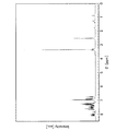
- 238000005481 NMR spectroscopy Methods 0.000 description 15
- 238000002347 injection Methods 0.000 description 15
- 239000007924 injection Substances 0.000 description 15
- 238000000034 method Methods 0.000 description 15
- 238000005259 measurement Methods 0.000 description 14
- IJGRMHOSHXDMSA-UHFFFAOYSA-N nitrogen Substances N#N IJGRMHOSHXDMSA-UHFFFAOYSA-N 0.000 description 14
- 239000010409 thin film Substances 0.000 description 14
- 150000002431 hydrogen Chemical class 0.000 description 12
- KDLHZDBZIXYQEI-UHFFFAOYSA-N palladium Substances [Pd] KDLHZDBZIXYQEI-UHFFFAOYSA-N 0.000 description 12
- 239000000243 solution Substances 0.000 description 12
- 125000000999 tert-butyl group Chemical group [H]C([H])([H])C(*)(C([H])([H])[H])C([H])([H])[H] 0.000 description 11
- 239000002131 composite material Substances 0.000 description 10
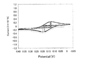
- 238000002484 cyclic voltammetry Methods 0.000 description 10
- 229910052757 nitrogen Inorganic materials 0.000 description 10
- 230000006866 deterioration Effects 0.000 description 9
- 230000005284 excitation Effects 0.000 description 9
- 238000004770 highest occupied molecular orbital Methods 0.000 description 9
- 230000005525 hole transport Effects 0.000 description 9
- 230000007935 neutral effect Effects 0.000 description 9
- ZMXDDKWLCZADIW-UHFFFAOYSA-N N,N-Dimethylformamide Chemical class CN(C)C=O ZMXDDKWLCZADIW-UHFFFAOYSA-N 0.000 description 8
- XLOMVQKBTHCTTD-UHFFFAOYSA-N Zinc monoxide Chemical compound [Zn]=O XLOMVQKBTHCTTD-UHFFFAOYSA-N 0.000 description 8
- AMWRITDGCCNYAT-UHFFFAOYSA-L hydroxy(oxo)manganese;manganese Chemical compound [Mn].O[Mn]=O.O[Mn]=O AMWRITDGCCNYAT-UHFFFAOYSA-L 0.000 description 8
- 230000003647 oxidation Effects 0.000 description 8
- FYKJPLLUCCMVTQ-UHFFFAOYSA-N 1-n-naphthalen-1-yl-4-n,4-n-diphenylbenzene-1,4-diamine Chemical compound C=1C=CC2=CC=CC=C2C=1NC(C=C1)=CC=C1N(C=1C=CC=CC=1)C1=CC=CC=C1 FYKJPLLUCCMVTQ-UHFFFAOYSA-N 0.000 description 7
- 125000001637 1-naphthyl group Chemical group [H]C1=C([H])C([H])=C2C(*)=C([H])C([H])=C([H])C2=C1[H] 0.000 description 7
- 229910052782 aluminium Inorganic materials 0.000 description 7
- 238000001704 evaporation Methods 0.000 description 7
- 230000005281 excited state Effects 0.000 description 7
- 239000011521 glass Substances 0.000 description 7
- 239000004973 liquid crystal related substance Substances 0.000 description 7
- 238000004768 lowest unoccupied molecular orbital Methods 0.000 description 7
- 239000000203 mixture Substances 0.000 description 7
- 229910000476 molybdenum oxide Inorganic materials 0.000 description 7
- 229910052697 platinum Inorganic materials 0.000 description 7
- MFRIHAYPQRLWNB-UHFFFAOYSA-N sodium tert-butoxide Chemical compound [Na+].CC(C)(C)[O-] MFRIHAYPQRLWNB-UHFFFAOYSA-N 0.000 description 7
- 239000007787 solid Substances 0.000 description 7
- DPECCMXOGAHFKQ-UHFFFAOYSA-N 3-N,6-N-dinaphthalen-1-yl-9-phenyl-3-N,6-N-bis[4-(N-phenylanilino)phenyl]carbazole-3,6-diamine Chemical compound C1=CC=CC=C1N(C=1C=CC(=CC=1)N(C=1C=C2C3=CC(=CC=C3N(C=3C=CC=CC=3)C2=CC=1)N(C=1C=CC(=CC=1)N(C=1C=CC=CC=1)C=1C=CC=CC=1)C=1C2=CC=CC=C2C=CC=1)C=1C2=CC=CC=C2C=CC=1)C1=CC=CC=C1 DPECCMXOGAHFKQ-UHFFFAOYSA-N 0.000 description 6
- PGBCBJIFTORPJN-UHFFFAOYSA-N 4-n-naphthalen-1-yl-1-n,1-n-diphenyl-4-n-(9-phenylcarbazol-3-yl)benzene-1,4-diamine Chemical compound C1=CC=CC=C1N(C=1C=CC(=CC=1)N(C=1C=C2C3=CC=CC=C3N(C=3C=CC=CC=3)C2=CC=1)C=1C2=CC=CC=C2C=CC=1)C1=CC=CC=C1 PGBCBJIFTORPJN-UHFFFAOYSA-N 0.000 description 6
- UHOVQNZJYSORNB-UHFFFAOYSA-N Benzene Chemical group C1=CC=CC=C1 UHOVQNZJYSORNB-UHFFFAOYSA-N 0.000 description 6
- CSNNHWWHGAXBCP-UHFFFAOYSA-L Magnesium sulfate Chemical compound [Mg+2].[O-][S+2]([O-])([O-])[O-] CSNNHWWHGAXBCP-UHFFFAOYSA-L 0.000 description 6
- 238000010521 absorption reaction Methods 0.000 description 6
- 150000001875 compounds Chemical class 0.000 description 6
- 238000000295 emission spectrum Methods 0.000 description 6
- 239000000706 filtrate Substances 0.000 description 6
- 150000002484 inorganic compounds Chemical class 0.000 description 6
- 229910010272 inorganic material Inorganic materials 0.000 description 6
- 239000012212 insulator Substances 0.000 description 6
- 229910052744 lithium Inorganic materials 0.000 description 6
- 229910052751 metal Inorganic materials 0.000 description 6
- 239000002184 metal Substances 0.000 description 6
- PQQKPALAQIIWST-UHFFFAOYSA-N oxomolybdenum Chemical compound [Mo]=O PQQKPALAQIIWST-UHFFFAOYSA-N 0.000 description 6
- 239000011541 reaction mixture Substances 0.000 description 6
- 230000009467 reduction Effects 0.000 description 6
- 0 C[Al]N*N([Al]*)[Al]* Chemical compound C[Al]N*N([Al]*)[Al]* 0.000 description 5
- WHXSMMKQMYFTQS-UHFFFAOYSA-N Lithium Chemical compound [Li] WHXSMMKQMYFTQS-UHFFFAOYSA-N 0.000 description 5
- NRTOMJZYCJJWKI-UHFFFAOYSA-N Titanium nitride Chemical compound [Ti]#N NRTOMJZYCJJWKI-UHFFFAOYSA-N 0.000 description 5
- 239000000956 alloy Substances 0.000 description 5
- 229910045601 alloy Inorganic materials 0.000 description 5
- XAGFODPZIPBFFR-UHFFFAOYSA-N aluminium Chemical compound [Al] XAGFODPZIPBFFR-UHFFFAOYSA-N 0.000 description 5
- 150000004982 aromatic amines Chemical class 0.000 description 5
- 230000001413 cellular effect Effects 0.000 description 5
- AMGQUBHHOARCQH-UHFFFAOYSA-N indium;oxotin Chemical compound [In].[Sn]=O AMGQUBHHOARCQH-UHFFFAOYSA-N 0.000 description 5
- 125000000040 m-tolyl group Chemical group [H]C1=C([H])C(*)=C([H])C(=C1[H])C([H])([H])[H] 0.000 description 5
- 239000011159 matrix material Substances 0.000 description 5
- 125000001037 p-tolyl group Chemical group [H]C1=C([H])C(=C([H])C([H])=C1*)C([H])([H])[H] 0.000 description 5
- 238000005192 partition Methods 0.000 description 5
- 125000001997 phenyl group Chemical group [H]C1=C([H])C([H])=C(*)C([H])=C1[H] 0.000 description 5
- 238000007789 sealing Methods 0.000 description 5
- VYPSYNLAJGMNEJ-UHFFFAOYSA-N silicon dioxide Inorganic materials O=[Si]=O VYPSYNLAJGMNEJ-UHFFFAOYSA-N 0.000 description 5
- KZPYGQFFRCFCPP-UHFFFAOYSA-N 1,1'-bis(diphenylphosphino)ferrocene Chemical compound [Fe+2].C1=CC=C[C-]1P(C=1C=CC=CC=1)C1=CC=CC=C1.C1=CC=C[C-]1P(C=1C=CC=CC=1)C1=CC=CC=C1 KZPYGQFFRCFCPP-UHFFFAOYSA-N 0.000 description 4
- 125000004198 2-fluorophenyl group Chemical group [H]C1=C([H])C(F)=C(*)C([H])=C1[H] 0.000 description 4
- 125000001622 2-naphthyl group Chemical group [H]C1=C([H])C([H])=C2C([H])=C(*)C([H])=C([H])C2=C1[H] 0.000 description 4
- 125000004180 3-fluorophenyl group Chemical group [H]C1=C([H])C(*)=C([H])C(F)=C1[H] 0.000 description 4
- 125000001255 4-fluorophenyl group Chemical group [H]C1=C([H])C(*)=C([H])C([H])=C1F 0.000 description 4
- 238000000862 absorption spectrum Methods 0.000 description 4
- 239000002585 base Substances 0.000 description 4
- XJHCXCQVJFPJIK-UHFFFAOYSA-M caesium fluoride Chemical compound [F-].[Cs+] XJHCXCQVJFPJIK-UHFFFAOYSA-M 0.000 description 4
- VBVAVBCYMYWNOU-UHFFFAOYSA-N coumarin 6 Chemical compound C1=CC=C2SC(C3=CC4=CC=C(C=C4OC3=O)N(CC)CC)=NC2=C1 VBVAVBCYMYWNOU-UHFFFAOYSA-N 0.000 description 4
- 238000004455 differential thermal analysis Methods 0.000 description 4
- 229910003437 indium oxide Inorganic materials 0.000 description 4
- PJXISJQVUVHSOJ-UHFFFAOYSA-N indium(iii) oxide Chemical compound [O-2].[O-2].[O-2].[In+3].[In+3] PJXISJQVUVHSOJ-UHFFFAOYSA-N 0.000 description 4
- 239000003446 ligand Substances 0.000 description 4
- 239000011777 magnesium Substances 0.000 description 4
- 239000004033 plastic Substances 0.000 description 4
- 229920003023 plastic Polymers 0.000 description 4
- 239000000047 product Substances 0.000 description 4
- 229910001925 ruthenium oxide Inorganic materials 0.000 description 4
- WOCIAKWEIIZHES-UHFFFAOYSA-N ruthenium(iv) oxide Chemical compound O=[Ru]=O WOCIAKWEIIZHES-UHFFFAOYSA-N 0.000 description 4
- 239000000565 sealant Substances 0.000 description 4
- 229910052710 silicon Inorganic materials 0.000 description 4
- 239000010703 silicon Substances 0.000 description 4
- 239000002356 single layer Substances 0.000 description 4
- KBLZDCFTQSIIOH-UHFFFAOYSA-M tetrabutylazanium;perchlorate Chemical compound [O-]Cl(=O)(=O)=O.CCCC[N+](CCCC)(CCCC)CCCC KBLZDCFTQSIIOH-UHFFFAOYSA-M 0.000 description 4
- 238000002411 thermogravimetry Methods 0.000 description 4
- 229910001935 vanadium oxide Inorganic materials 0.000 description 4
- 239000011701 zinc Substances 0.000 description 4
- UKSZBOKPHAQOMP-SVLSSHOZSA-N (1e,4e)-1,5-diphenylpenta-1,4-dien-3-one;palladium Chemical compound [Pd].C=1C=CC=CC=1\C=C\C(=O)\C=C\C1=CC=CC=C1.C=1C=CC=CC=1\C=C\C(=O)\C=C\C1=CC=CC=C1 UKSZBOKPHAQOMP-SVLSSHOZSA-N 0.000 description 3
- UFHFLCQGNIYNRP-UHFFFAOYSA-N Hydrogen Chemical compound [H][H] UFHFLCQGNIYNRP-UHFFFAOYSA-N 0.000 description 3
- PXHVJJICTQNCMI-UHFFFAOYSA-N Nickel Chemical compound [Ni] PXHVJJICTQNCMI-UHFFFAOYSA-N 0.000 description 3
- CTQNGGLPUBDAKN-UHFFFAOYSA-N O-Xylene Chemical compound CC1=CC=CC=C1C CTQNGGLPUBDAKN-UHFFFAOYSA-N 0.000 description 3
- 239000007983 Tris buffer Substances 0.000 description 3
- 229910052783 alkali metal Inorganic materials 0.000 description 3
- PNEYBMLMFCGWSK-UHFFFAOYSA-N aluminium oxide Inorganic materials [O-2].[O-2].[O-2].[Al+3].[Al+3] PNEYBMLMFCGWSK-UHFFFAOYSA-N 0.000 description 3
- 230000015572 biosynthetic process Effects 0.000 description 3
- 239000011575 calcium Substances 0.000 description 3
- 150000001716 carbazoles Chemical class 0.000 description 3
- 239000003054 catalyst Substances 0.000 description 3
- 239000011651 chromium Substances 0.000 description 3
- 125000001495 ethyl group Chemical group [H]C([H])([H])C([H])([H])* 0.000 description 3
- 230000008020 evaporation Effects 0.000 description 3
- 238000001914 filtration Methods 0.000 description 3
- 238000010438 heat treatment Methods 0.000 description 3
- PQXKHYXIUOZZFA-UHFFFAOYSA-M lithium fluoride Chemical compound [Li+].[F-] PQXKHYXIUOZZFA-UHFFFAOYSA-M 0.000 description 3
- 229910052943 magnesium sulfate Inorganic materials 0.000 description 3
- 235000019341 magnesium sulphate Nutrition 0.000 description 3
- 229910044991 metal oxide Inorganic materials 0.000 description 3
- 150000004706 metal oxides Chemical class 0.000 description 3
- 125000002496 methyl group Chemical group [H]C([H])([H])* 0.000 description 3
- QGLKJKCYBOYXKC-UHFFFAOYSA-N nonaoxidotritungsten Chemical compound O=[W]1(=O)O[W](=O)(=O)O[W](=O)(=O)O1 QGLKJKCYBOYXKC-UHFFFAOYSA-N 0.000 description 3
- 239000003921 oil Substances 0.000 description 3
- 239000012044 organic layer Substances 0.000 description 3
- 239000003566 sealing material Substances 0.000 description 3
- 238000010898 silica gel chromatography Methods 0.000 description 3
- HPALAKNZSZLMCH-UHFFFAOYSA-M sodium;chloride;hydrate Chemical class O.[Na+].[Cl-] HPALAKNZSZLMCH-UHFFFAOYSA-M 0.000 description 3
- 239000002904 solvent Substances 0.000 description 3
- 238000000967 suction filtration Methods 0.000 description 3
- 238000003786 synthesis reaction Methods 0.000 description 3
- FKHIFSZMMVMEQY-UHFFFAOYSA-N talc Chemical compound [Mg+2].[O-][Si]([O-])=O FKHIFSZMMVMEQY-UHFFFAOYSA-N 0.000 description 3
- 229910001930 tungsten oxide Inorganic materials 0.000 description 3
- 238000007740 vapor deposition Methods 0.000 description 3
- XLYOFNOQVPJJNP-UHFFFAOYSA-N water Substances O XLYOFNOQVPJJNP-UHFFFAOYSA-N 0.000 description 3
- 239000011787 zinc oxide Substances 0.000 description 3
- RUFPHBVGCFYCNW-UHFFFAOYSA-N 1-naphthylamine Chemical compound C1=CC=C2C(N)=CC=CC2=C1 RUFPHBVGCFYCNW-UHFFFAOYSA-N 0.000 description 2
- XUVKSPPGPPFPQN-UHFFFAOYSA-N 10-Methyl-9(10H)-acridone Chemical compound C1=CC=C2N(C)C3=CC=CC=C3C(=O)C2=C1 XUVKSPPGPPFPQN-UHFFFAOYSA-N 0.000 description 2
- 125000004105 2-pyridyl group Chemical group N1=C([*])C([H])=C([H])C([H])=C1[H] 0.000 description 2
- ZVFQEOPUXVPSLB-UHFFFAOYSA-N 3-(4-tert-butylphenyl)-4-phenyl-5-(4-phenylphenyl)-1,2,4-triazole Chemical compound C1=CC(C(C)(C)C)=CC=C1C(N1C=2C=CC=CC=2)=NN=C1C1=CC=C(C=2C=CC=CC=2)C=C1 ZVFQEOPUXVPSLB-UHFFFAOYSA-N 0.000 description 2
- DHDHJYNTEFLIHY-UHFFFAOYSA-N 4,7-diphenyl-1,10-phenanthroline Chemical compound C1=CC=CC=C1C1=CC=NC2=C1C=CC1=C(C=3C=CC=CC=3)C=CN=C21 DHDHJYNTEFLIHY-UHFFFAOYSA-N 0.000 description 2
- UJOBWOGCFQCDNV-UHFFFAOYSA-N 9H-carbazole Chemical compound C1=CC=C2C3=CC=CC=C3NC2=C1 UJOBWOGCFQCDNV-UHFFFAOYSA-N 0.000 description 2
- 229910017073 AlLi Inorganic materials 0.000 description 2
- XKRFYHLGVUSROY-UHFFFAOYSA-N Argon Chemical compound [Ar] XKRFYHLGVUSROY-UHFFFAOYSA-N 0.000 description 2
- VYZAMTAEIAYCRO-UHFFFAOYSA-N Chromium Chemical compound [Cr] VYZAMTAEIAYCRO-UHFFFAOYSA-N 0.000 description 2
- 229910052693 Europium Inorganic materials 0.000 description 2
- FYYHWMGAXLPEAU-UHFFFAOYSA-N Magnesium Chemical compound [Mg] FYYHWMGAXLPEAU-UHFFFAOYSA-N 0.000 description 2
- PHXQIAWFIIMOKG-UHFFFAOYSA-N NClO Chemical compound NClO PHXQIAWFIIMOKG-UHFFFAOYSA-N 0.000 description 2
- 229920001609 Poly(3,4-ethylenedioxythiophene) Polymers 0.000 description 2
- GWEVSGVZZGPLCZ-UHFFFAOYSA-N Titan oxide Chemical compound O=[Ti]=O GWEVSGVZZGPLCZ-UHFFFAOYSA-N 0.000 description 2
- WGLPBDUCMAPZCE-UHFFFAOYSA-N Trioxochromium Chemical compound O=[Cr](=O)=O WGLPBDUCMAPZCE-UHFFFAOYSA-N 0.000 description 2
- HCHKCACWOHOZIP-UHFFFAOYSA-N Zinc Chemical compound [Zn] HCHKCACWOHOZIP-UHFFFAOYSA-N 0.000 description 2
- XHCLAFWTIXFWPH-UHFFFAOYSA-N [O-2].[O-2].[O-2].[O-2].[O-2].[V+5].[V+5] Chemical compound [O-2].[O-2].[O-2].[O-2].[O-2].[V+5].[V+5] XHCLAFWTIXFWPH-UHFFFAOYSA-N 0.000 description 2
- NIXOWILDQLNWCW-UHFFFAOYSA-N acrylic acid group Chemical group C(C=C)(=O)O NIXOWILDQLNWCW-UHFFFAOYSA-N 0.000 description 2
- 150000001340 alkali metals Chemical class 0.000 description 2
- 229910052784 alkaline earth metal Inorganic materials 0.000 description 2
- 150000001342 alkaline earth metals Chemical class 0.000 description 2
- 150000001412 amines Chemical class 0.000 description 2
- 239000003125 aqueous solvent Substances 0.000 description 2
- 229910052791 calcium Inorganic materials 0.000 description 2
- 230000008859 change Effects 0.000 description 2
- 229910052804 chromium Inorganic materials 0.000 description 2
- 229910000423 chromium oxide Inorganic materials 0.000 description 2
- 238000010549 co-Evaporation Methods 0.000 description 2
- 239000010949 copper Substances 0.000 description 2
- 238000002425 crystallisation Methods 0.000 description 2
- 230000008025 crystallization Effects 0.000 description 2
- 238000007872 degassing Methods 0.000 description 2
- 238000001035 drying Methods 0.000 description 2
- OGPBJKLSAFTDLK-UHFFFAOYSA-N europium atom Chemical compound [Eu] OGPBJKLSAFTDLK-UHFFFAOYSA-N 0.000 description 2
- 230000002349 favourable effect Effects 0.000 description 2
- 239000011152 fibreglass Substances 0.000 description 2
- 239000010931 gold Substances 0.000 description 2
- 229910000449 hafnium oxide Inorganic materials 0.000 description 2
- 238000005286 illumination Methods 0.000 description 2
- 229910052749 magnesium Inorganic materials 0.000 description 2
- 238000004519 manufacturing process Methods 0.000 description 2
- IBHBKWKFFTZAHE-UHFFFAOYSA-N n-[4-[4-(n-naphthalen-1-ylanilino)phenyl]phenyl]-n-phenylnaphthalen-1-amine Chemical group C1=CC=CC=C1N(C=1C2=CC=CC=C2C=CC=1)C1=CC=C(C=2C=CC(=CC=2)N(C=2C=CC=CC=2)C=2C3=CC=CC=C3C=CC=2)C=C1 IBHBKWKFFTZAHE-UHFFFAOYSA-N 0.000 description 2
- 125000004108 n-butyl group Chemical group [H]C([H])([H])C([H])([H])C([H])([H])C([H])([H])* 0.000 description 2
- 239000012299 nitrogen atmosphere Substances 0.000 description 2
- AHLBNYSZXLDEJQ-FWEHEUNISA-N orlistat Chemical compound CCCCCCCCCCC[C@H](OC(=O)[C@H](CC(C)C)NC=O)C[C@@H]1OC(=O)[C@H]1CCCCCC AHLBNYSZXLDEJQ-FWEHEUNISA-N 0.000 description 2
- BPUBBGLMJRNUCC-UHFFFAOYSA-N oxygen(2-);tantalum(5+) Chemical compound [O-2].[O-2].[O-2].[O-2].[O-2].[Ta+5].[Ta+5] BPUBBGLMJRNUCC-UHFFFAOYSA-N 0.000 description 2
- RVTZCBVAJQQJTK-UHFFFAOYSA-N oxygen(2-);zirconium(4+) Chemical compound [O-2].[O-2].[Zr+4] RVTZCBVAJQQJTK-UHFFFAOYSA-N 0.000 description 2
- IEQIEDJGQAUEQZ-UHFFFAOYSA-N phthalocyanine Chemical class N1C(N=C2C3=CC=CC=C3C(N=C3C4=CC=CC=C4C(=N4)N3)=N2)=C(C=CC=C2)C2=C1N=C1C2=CC=CC=C2C4=N1 IEQIEDJGQAUEQZ-UHFFFAOYSA-N 0.000 description 2
- 229920002620 polyvinyl fluoride Polymers 0.000 description 2
- 125000002924 primary amino group Chemical group [H]N([H])* 0.000 description 2
- 229910052761 rare earth metal Chemical class 0.000 description 2
- 150000002910 rare earth metals Chemical class 0.000 description 2
- 229910003449 rhenium oxide Inorganic materials 0.000 description 2
- YYMBJDOZVAITBP-UHFFFAOYSA-N rubrene Chemical compound C1=CC=CC=C1C(C1=C(C=2C=CC=CC=2)C2=CC=CC=C2C(C=2C=CC=CC=2)=C11)=C(C=CC=C2)C2=C1C1=CC=CC=C1 YYMBJDOZVAITBP-UHFFFAOYSA-N 0.000 description 2
- 229910052709 silver Inorganic materials 0.000 description 2
- NDVLTYZPCACLMA-UHFFFAOYSA-N silver oxide Chemical compound [O-2].[Ag+].[Ag+] NDVLTYZPCACLMA-UHFFFAOYSA-N 0.000 description 2
- 238000004544 sputter deposition Methods 0.000 description 2
- 239000003115 supporting electrolyte Substances 0.000 description 2
- 230000002194 synthesizing effect Effects 0.000 description 2
- 229910001936 tantalum oxide Inorganic materials 0.000 description 2
- OGIDPMRJRNCKJF-UHFFFAOYSA-N titanium oxide Inorganic materials [Ti]=O OGIDPMRJRNCKJF-UHFFFAOYSA-N 0.000 description 2
- TVIVIEFSHFOWTE-UHFFFAOYSA-K tri(quinolin-8-yloxy)alumane Chemical compound [Al+3].C1=CN=C2C([O-])=CC=CC2=C1.C1=CN=C2C([O-])=CC=CC2=C1.C1=CN=C2C([O-])=CC=CC2=C1 TVIVIEFSHFOWTE-UHFFFAOYSA-K 0.000 description 2
- BWHDROKFUHTORW-UHFFFAOYSA-N tritert-butylphosphane Chemical compound CC(C)(C)P(C(C)(C)C)C(C)(C)C BWHDROKFUHTORW-UHFFFAOYSA-N 0.000 description 2
- WFKWXMTUELFFGS-UHFFFAOYSA-N tungsten Chemical compound [W] WFKWXMTUELFFGS-UHFFFAOYSA-N 0.000 description 2
- 229910052721 tungsten Inorganic materials 0.000 description 2
- 239000010937 tungsten Substances 0.000 description 2
- 238000000870 ultraviolet spectroscopy Methods 0.000 description 2
- 229910052725 zinc Inorganic materials 0.000 description 2
- 229910001928 zirconium oxide Inorganic materials 0.000 description 2
- OURODNXVJUWPMZ-UHFFFAOYSA-N 1,2-diphenylanthracene Chemical compound C1=CC=CC=C1C1=CC=C(C=C2C(C=CC=C2)=C2)C2=C1C1=CC=CC=C1 OURODNXVJUWPMZ-UHFFFAOYSA-N 0.000 description 1
- IYZMXHQDXZKNCY-UHFFFAOYSA-N 1-n,1-n-diphenyl-4-n,4-n-bis[4-(n-phenylanilino)phenyl]benzene-1,4-diamine Chemical compound C1=CC=CC=C1N(C=1C=CC(=CC=1)N(C=1C=CC(=CC=1)N(C=1C=CC=CC=1)C=1C=CC=CC=1)C=1C=CC(=CC=1)N(C=1C=CC=CC=1)C=1C=CC=CC=1)C1=CC=CC=C1 IYZMXHQDXZKNCY-UHFFFAOYSA-N 0.000 description 1
- FBTOLQFRGURPJH-UHFFFAOYSA-N 1-phenyl-9h-carbazole Chemical compound C1=CC=CC=C1C1=CC=CC2=C1NC1=CC=CC=C12 FBTOLQFRGURPJH-UHFFFAOYSA-N 0.000 description 1
- GOKIEMZASYETFM-UHFFFAOYSA-N 10-phenylacridin-9-one Chemical compound C12=CC=CC=C2C(=O)C2=CC=CC=C2N1C1=CC=CC=C1 GOKIEMZASYETFM-UHFFFAOYSA-N 0.000 description 1
- VFMUXPQZKOKPOF-UHFFFAOYSA-N 2,3,7,8,12,13,17,18-octaethyl-21,23-dihydroporphyrin platinum Chemical compound [Pt].CCc1c(CC)c2cc3[nH]c(cc4nc(cc5[nH]c(cc1n2)c(CC)c5CC)c(CC)c4CC)c(CC)c3CC VFMUXPQZKOKPOF-UHFFFAOYSA-N 0.000 description 1
- STTGYIUESPWXOW-UHFFFAOYSA-N 2,9-dimethyl-4,7-diphenyl-1,10-phenanthroline Chemical compound C=12C=CC3=C(C=4C=CC=CC=4)C=C(C)N=C3C2=NC(C)=CC=1C1=CC=CC=C1 STTGYIUESPWXOW-UHFFFAOYSA-N 0.000 description 1
- UOCMXZLNHQBBOS-UHFFFAOYSA-N 2-(1,3-benzoxazol-2-yl)phenol zinc Chemical compound [Zn].Oc1ccccc1-c1nc2ccccc2o1.Oc1ccccc1-c1nc2ccccc2o1 UOCMXZLNHQBBOS-UHFFFAOYSA-N 0.000 description 1
- FQJQNLKWTRGIEB-UHFFFAOYSA-N 2-(4-tert-butylphenyl)-5-[3-[5-(4-tert-butylphenyl)-1,3,4-oxadiazol-2-yl]phenyl]-1,3,4-oxadiazole Chemical compound C1=CC(C(C)(C)C)=CC=C1C1=NN=C(C=2C=C(C=CC=2)C=2OC(=NN=2)C=2C=CC(=CC=2)C(C)(C)C)O1 FQJQNLKWTRGIEB-UHFFFAOYSA-N 0.000 description 1
- PJZHSTLLJNQKAI-UHFFFAOYSA-N 2-methyl-4h-pyran Chemical compound CC1=CCC=CO1 PJZHSTLLJNQKAI-UHFFFAOYSA-N 0.000 description 1
- OBAJPWYDYFEBTF-UHFFFAOYSA-N 2-tert-butyl-9,10-dinaphthalen-2-ylanthracene Chemical compound C1=CC=CC2=CC(C3=C4C=CC=CC4=C(C=4C=C5C=CC=CC5=CC=4)C4=CC=C(C=C43)C(C)(C)C)=CC=C21 OBAJPWYDYFEBTF-UHFFFAOYSA-N 0.000 description 1
- AWGAUYXFWGUFNE-UHFFFAOYSA-N 3,6-diiodo-9-phenylcarbazole Chemical compound C12=CC=C(I)C=C2C2=CC(I)=CC=C2N1C1=CC=CC=C1 AWGAUYXFWGUFNE-UHFFFAOYSA-N 0.000 description 1
- PZLZJGZGJHZQAU-UHFFFAOYSA-N 3-(4-tert-butylphenyl)-4-(4-ethylphenyl)-5-(4-phenylphenyl)-1,2,4-triazole Chemical compound C1=CC(CC)=CC=C1N1C(C=2C=CC(=CC=2)C(C)(C)C)=NN=C1C1=CC=C(C=2C=CC=CC=2)C=C1 PZLZJGZGJHZQAU-UHFFFAOYSA-N 0.000 description 1
- PJUAIXDOXUXBDR-UHFFFAOYSA-N 3-iodo-9-phenylcarbazole Chemical compound C12=CC=CC=C2C2=CC(I)=CC=C2N1C1=CC=CC=C1 PJUAIXDOXUXBDR-UHFFFAOYSA-N 0.000 description 1
- OGGKVJMNFFSDEV-UHFFFAOYSA-N 3-methyl-n-[4-[4-(n-(3-methylphenyl)anilino)phenyl]phenyl]-n-phenylaniline Chemical group CC1=CC=CC(N(C=2C=CC=CC=2)C=2C=CC(=CC=2)C=2C=CC(=CC=2)N(C=2C=CC=CC=2)C=2C=C(C)C=CC=2)=C1 OGGKVJMNFFSDEV-UHFFFAOYSA-N 0.000 description 1
- SQTLUXJWUCHKMT-UHFFFAOYSA-N 4-bromo-n,n-diphenylaniline Chemical compound C1=CC(Br)=CC=C1N(C=1C=CC=CC=1)C1=CC=CC=C1 SQTLUXJWUCHKMT-UHFFFAOYSA-N 0.000 description 1
- SCZWJXTUYYSKGF-UHFFFAOYSA-N 5,12-dimethylquinolino[2,3-b]acridine-7,14-dione Chemical compound CN1C2=CC=CC=C2C(=O)C2=C1C=C1C(=O)C3=CC=CC=C3N(C)C1=C2 SCZWJXTUYYSKGF-UHFFFAOYSA-N 0.000 description 1
- FCNCGHJSNVOIKE-UHFFFAOYSA-N 9,10-diphenylanthracene Chemical compound C1=CC=CC=C1C(C1=CC=CC=C11)=C(C=CC=C2)C2=C1C1=CC=CC=C1 FCNCGHJSNVOIKE-UHFFFAOYSA-N 0.000 description 1
- 239000004925 Acrylic resin Substances 0.000 description 1
- 229920000178 Acrylic resin Polymers 0.000 description 1
- 229920002799 BoPET Polymers 0.000 description 1
- MSDMPJCOOXURQD-UHFFFAOYSA-N C545T Chemical compound C1=CC=C2SC(C3=CC=4C=C5C6=C(C=4OC3=O)C(C)(C)CCN6CCC5(C)C)=NC2=C1 MSDMPJCOOXURQD-UHFFFAOYSA-N 0.000 description 1
- 229910004261 CaF 2 Inorganic materials 0.000 description 1
- OYPRJOBELJOOCE-UHFFFAOYSA-N Calcium Chemical compound [Ca] OYPRJOBELJOOCE-UHFFFAOYSA-N 0.000 description 1
- 241000284156 Clerodendrum quadriloculare Species 0.000 description 1
- RYGMFSIKBFXOCR-UHFFFAOYSA-N Copper Chemical compound [Cu] RYGMFSIKBFXOCR-UHFFFAOYSA-N 0.000 description 1
- 239000004593 Epoxy Substances 0.000 description 1
- XEEYBQQBJWHFJM-UHFFFAOYSA-N Iron Chemical compound [Fe] XEEYBQQBJWHFJM-UHFFFAOYSA-N 0.000 description 1
- 229910017911 MgIn Inorganic materials 0.000 description 1
- ZOKXTWBITQBERF-UHFFFAOYSA-N Molybdenum Chemical compound [Mo] ZOKXTWBITQBERF-UHFFFAOYSA-N 0.000 description 1
- 239000005041 Mylar™ Substances 0.000 description 1
- ZCQWOFVYLHDMMC-UHFFFAOYSA-N Oxazole Chemical compound C1=COC=N1 ZCQWOFVYLHDMMC-UHFFFAOYSA-N 0.000 description 1
- NRCMAYZCPIVABH-UHFFFAOYSA-N Quinacridone Chemical class N1C2=CC=CC=C2C(=O)C2=C1C=C1C(=O)C3=CC=CC=C3NC1=C2 NRCMAYZCPIVABH-UHFFFAOYSA-N 0.000 description 1
- PJANXHGTPQOBST-VAWYXSNFSA-N Stilbene Natural products C=1C=CC=CC=1/C=C/C1=CC=CC=C1 PJANXHGTPQOBST-VAWYXSNFSA-N 0.000 description 1
- FZWLAAWBMGSTSO-UHFFFAOYSA-N Thiazole Chemical compound C1=CSC=N1 FZWLAAWBMGSTSO-UHFFFAOYSA-N 0.000 description 1
- ATJFFYVFTNAWJD-UHFFFAOYSA-N Tin Chemical compound [Sn] ATJFFYVFTNAWJD-UHFFFAOYSA-N 0.000 description 1
- 229910052769 Ytterbium Inorganic materials 0.000 description 1
- FZEYVTFCMJSGMP-UHFFFAOYSA-N acridone Chemical class C1=CC=C2C(=O)C3=CC=CC=C3NC2=C1 FZEYVTFCMJSGMP-UHFFFAOYSA-N 0.000 description 1
- 150000001339 alkali metal compounds Chemical class 0.000 description 1
- 150000001341 alkaline earth metal compounds Chemical class 0.000 description 1
- 238000013459 approach Methods 0.000 description 1
- 229910052786 argon Inorganic materials 0.000 description 1
- 150000001491 aromatic compounds Chemical class 0.000 description 1
- 150000004945 aromatic hydrocarbons Chemical class 0.000 description 1
- 239000012298 atmosphere Substances 0.000 description 1
- QVGXLLKOCUKJST-UHFFFAOYSA-N atomic oxygen Chemical compound [O] QVGXLLKOCUKJST-UHFFFAOYSA-N 0.000 description 1
- WZJYKHNJTSNBHV-UHFFFAOYSA-N benzo[h]quinoline Chemical group C1=CN=C2C3=CC=CC=C3C=CC2=C1 WZJYKHNJTSNBHV-UHFFFAOYSA-N 0.000 description 1
- GQVWHWAWLPCBHB-UHFFFAOYSA-L beryllium;benzo[h]quinolin-10-olate Chemical compound [Be+2].C1=CC=NC2=C3C([O-])=CC=CC3=CC=C21.C1=CC=NC2=C3C([O-])=CC=CC3=CC=C21 GQVWHWAWLPCBHB-UHFFFAOYSA-L 0.000 description 1
- UFVXQDWNSAGPHN-UHFFFAOYSA-K bis[(2-methylquinolin-8-yl)oxy]-(4-phenylphenoxy)alumane Chemical compound [Al+3].C1=CC=C([O-])C2=NC(C)=CC=C21.C1=CC=C([O-])C2=NC(C)=CC=C21.C1=CC([O-])=CC=C1C1=CC=CC=C1 UFVXQDWNSAGPHN-UHFFFAOYSA-K 0.000 description 1
- 230000000903 blocking effect Effects 0.000 description 1
- XZCJVWCMJYNSQO-UHFFFAOYSA-N butyl pbd Chemical compound C1=CC(C(C)(C)C)=CC=C1C1=NN=C(C=2C=CC(=CC=2)C=2C=CC=CC=2)O1 XZCJVWCMJYNSQO-UHFFFAOYSA-N 0.000 description 1
- 229910052792 caesium Inorganic materials 0.000 description 1
- TVFDJXOCXUVLDH-UHFFFAOYSA-N caesium atom Chemical compound [Cs] TVFDJXOCXUVLDH-UHFFFAOYSA-N 0.000 description 1
- WUKWITHWXAAZEY-UHFFFAOYSA-L calcium difluoride Chemical compound [F-].[F-].[Ca+2] WUKWITHWXAAZEY-UHFFFAOYSA-L 0.000 description 1
- 239000000969 carrier Substances 0.000 description 1
- 239000010406 cathode material Substances 0.000 description 1
- 229910017052 cobalt Inorganic materials 0.000 description 1
- 239000010941 cobalt Substances 0.000 description 1
- GUTLYIVDDKVIGB-UHFFFAOYSA-N cobalt atom Chemical compound [Co] GUTLYIVDDKVIGB-UHFFFAOYSA-N 0.000 description 1
- 239000004020 conductor Substances 0.000 description 1
- 150000004696 coordination complex Chemical class 0.000 description 1
- 229910052802 copper Inorganic materials 0.000 description 1
- 150000004775 coumarins Chemical class 0.000 description 1
- 230000007547 defect Effects 0.000 description 1
- 239000000412 dendrimer Substances 0.000 description 1
- 229920000736 dendritic polymer Polymers 0.000 description 1
- 238000000151 deposition Methods 0.000 description 1
- 238000011161 development Methods 0.000 description 1
- WMKGGPCROCCUDY-PHEQNACWSA-N dibenzylideneacetone Chemical compound C=1C=CC=CC=1\C=C\C(=O)\C=C\C1=CC=CC=C1 WMKGGPCROCCUDY-PHEQNACWSA-N 0.000 description 1
- 125000002147 dimethylamino group Chemical group [H]C([H])([H])N(*)C([H])([H])[H] 0.000 description 1
- 230000005611 electricity Effects 0.000 description 1
- 239000000945 filler Substances 0.000 description 1
- PCHJSUWPFVWCPO-UHFFFAOYSA-N gold Chemical compound [Au] PCHJSUWPFVWCPO-UHFFFAOYSA-N 0.000 description 1
- 229910052737 gold Inorganic materials 0.000 description 1
- 230000005283 ground state Effects 0.000 description 1
- WIHZLLGSGQNAGK-UHFFFAOYSA-N hafnium(4+);oxygen(2-) Chemical compound [O-2].[O-2].[Hf+4] WIHZLLGSGQNAGK-UHFFFAOYSA-N 0.000 description 1
- RBTKNAXYKSUFRK-UHFFFAOYSA-N heliogen blue Chemical compound [Cu].[N-]1C2=C(C=CC=C3)C3=C1N=C([N-]1)C3=CC=CC=C3C1=NC([N-]1)=C(C=CC=C3)C3=C1N=C([N-]1)C3=CC=CC=C3C1=N2 RBTKNAXYKSUFRK-UHFFFAOYSA-N 0.000 description 1
- 230000006872 improvement Effects 0.000 description 1
- 239000011261 inert gas Substances 0.000 description 1
- 230000007246 mechanism Effects 0.000 description 1
- 239000007769 metal material Substances 0.000 description 1
- 150000002739 metals Chemical class 0.000 description 1
- 238000002156 mixing Methods 0.000 description 1
- 229910052750 molybdenum Inorganic materials 0.000 description 1
- 239000011733 molybdenum Substances 0.000 description 1
- 229910052759 nickel Inorganic materials 0.000 description 1
- 150000004767 nitrides Chemical class 0.000 description 1
- QJGQUHMNIGDVPM-UHFFFAOYSA-N nitrogen group Chemical group [N] QJGQUHMNIGDVPM-UHFFFAOYSA-N 0.000 description 1
- 150000004880 oxines Chemical class 0.000 description 1
- DYIZHKNUQPHNJY-UHFFFAOYSA-N oxorhenium Chemical compound [Re]=O DYIZHKNUQPHNJY-UHFFFAOYSA-N 0.000 description 1
- 239000001301 oxygen Substances 0.000 description 1
- 229910052760 oxygen Inorganic materials 0.000 description 1
- 229910052763 palladium Inorganic materials 0.000 description 1
- 230000000737 periodic effect Effects 0.000 description 1
- 150000003057 platinum Chemical class 0.000 description 1
- 229920000172 poly(styrenesulfonic acid) Polymers 0.000 description 1
- 229920000728 polyester Polymers 0.000 description 1
- 229920000642 polymer Polymers 0.000 description 1
- 238000012545 processing Methods 0.000 description 1
- 230000001737 promoting effect Effects 0.000 description 1
- 239000010453 quartz Substances 0.000 description 1
- 238000010791 quenching Methods 0.000 description 1
- 230000000171 quenching effect Effects 0.000 description 1
- 125000002943 quinolinyl group Chemical group N1=C(C=CC2=CC=CC=C12)* 0.000 description 1
- 238000006479 redox reaction Methods 0.000 description 1
- 238000012827 research and development Methods 0.000 description 1
- 239000011347 resin Substances 0.000 description 1
- 229920005989 resin Polymers 0.000 description 1
- 230000004044 response Effects 0.000 description 1
- 229910052814 silicon oxide Inorganic materials 0.000 description 1
- 229910001923 silver oxide Inorganic materials 0.000 description 1
- 238000003980 solgel method Methods 0.000 description 1
- 238000004528 spin coating Methods 0.000 description 1
- 230000003068 static effect Effects 0.000 description 1
- PJANXHGTPQOBST-UHFFFAOYSA-N stilbene Chemical compound C=1C=CC=CC=1C=CC1=CC=CC=C1 PJANXHGTPQOBST-UHFFFAOYSA-N 0.000 description 1
- 235000021286 stilbenes Nutrition 0.000 description 1
- 229910052712 strontium Inorganic materials 0.000 description 1
- CIOAGBVUUVVLOB-UHFFFAOYSA-N strontium atom Chemical compound [Sr] CIOAGBVUUVVLOB-UHFFFAOYSA-N 0.000 description 1
- 125000005504 styryl group Chemical group 0.000 description 1
- 150000003613 toluenes Chemical class 0.000 description 1
- 238000012546 transfer Methods 0.000 description 1
- 229910052723 transition metal Inorganic materials 0.000 description 1
- 150000003624 transition metals Chemical class 0.000 description 1
- ODHXBMXNKOYIBV-UHFFFAOYSA-N triphenylamine Chemical compound C1=CC=CC=C1N(C=1C=CC=CC=1)C1=CC=CC=C1 ODHXBMXNKOYIBV-UHFFFAOYSA-N 0.000 description 1
- 238000007738 vacuum evaporation Methods 0.000 description 1
- 239000008096 xylene Substances 0.000 description 1
- NAWDYIZEMPQZHO-UHFFFAOYSA-N ytterbium Chemical compound [Yb] NAWDYIZEMPQZHO-UHFFFAOYSA-N 0.000 description 1
- YVTHLONGBIQYBO-UHFFFAOYSA-N zinc indium(3+) oxygen(2-) Chemical compound [O--].[Zn++].[In+3] YVTHLONGBIQYBO-UHFFFAOYSA-N 0.000 description 1
Images


Abstract
Description
本発明はアリールアミン化合物およびその合成方法に関する。また、アリールアミンを用いて得られた発光素子用材料、およびその発光素子用材料を用いて作製された発光素子、電子機器に関する。 The present invention relates to an arylamine compound and a synthesis method thereof. In addition, the present invention relates to a light-emitting element material obtained using arylamine, a light-emitting element manufactured using the light-emitting element material, and an electronic device.
近年、発光性の有機化合物を用いた発光素子の研究開発が盛んに行われている。これら発光素子の基本的な構成は、一対の電極間に発光性の有機化合物を含む層を挟んだものである。この素子に電圧を印加することにより、一対の電極から電子および正孔がそれぞれ発光性の有機化合物を含む層に注入され、電流が流れる。そして、それらキャリア(電子および正孔)が再結合することにより、発光性の有機化合物が励起状態を形成し、その励起状態が基底状態に戻る際に発光する。このようなメカニズムから、このような発光素子は、電流励起型の発光素子と呼ばれる。 In recent years, research and development of light-emitting elements using light-emitting organic compounds have been actively conducted. The basic structure of these light-emitting elements is such that a layer containing a light-emitting organic compound is sandwiched between a pair of electrodes. By applying a voltage to this element, electrons and holes are injected from the pair of electrodes to the layer containing a light-emitting organic compound, and current flows. Then, these carriers (electrons and holes) recombine, whereby the light-emitting organic compound forms an excited state, and emits light when the excited state returns to the ground state. Due to such a mechanism, such a light-emitting element is referred to as a current-excitation light-emitting element.
なお、有機化合物が形成する励起状態の種類としては、一重項励起状態と三重項励起状態が可能であり、一重項励起状態からの発光が蛍光、三重項励起状態からの発光が燐光と呼ばれている。 Note that the excited states formed by the organic compound can be singlet excited state or triplet excited state. Light emission from the singlet excited state is called fluorescence, and light emission from the triplet excited state is called phosphorescence. ing.
このような発光素子は、例えば0.1μm程度の有機薄膜で形成されるため、薄型軽量に作製できることが大きな利点である。また、キャリアが注入されてから発光に至るまでの時間は1μ秒程度あるいはそれ以下であるため、非常に応答速度が速いことも特長の一つである。これらの特性は、フラットパネルディスプレイ素子として好適であると考えられている。 Such a light-emitting element is formed of an organic thin film having a thickness of, for example, about 0.1 μm. In addition, since the time from the injection of the carrier to the light emission is about 1 μsec or less, one of the features is that the response speed is very fast. These characteristics are considered suitable for flat panel display elements.
また、これらの発光素子は膜状に形成されるため、大面積の素子を形成することにより、面状の発光を容易に得ることができる。このことは、白熱電球やLEDに代表される点光源、あるいは蛍光灯に代表される線光源では得難い特色であるため、照明等に応用できる面光源としての利用価値も高い。 In addition, since these light-emitting elements are formed in a film shape, planar light emission can be easily obtained by forming a large-area element. This is a feature that is difficult to obtain with a point light source typified by an incandescent bulb or LED, or a line light source typified by a fluorescent lamp, and therefore has a high utility value as a surface light source applicable to illumination or the like.
このような発光素子に関しては、その素子特性を向上させる上で、材料に依存した問題が多く、これらを克服するために素子構造の改良や材料開発等が行われている。 With respect to such a light emitting element, there are many problems depending on the material in improving the element characteristics, and improvement of the element structure, material development, and the like have been performed in order to overcome these problems.
電流励起型の発光素子の劣化の一因として、一対の電極間に形成された発光物質を含む層に含まれる材料の劣化が挙げられる。電流励起型の発光素子において、発光物質を含む層を電流が流れることにより、発光物質を含む層に含まれる材料は酸化反応および還元反応を繰り返すことになる。酸化反応または還元反応により分解されやすい材料が発光物質を含む層に含まれていると、その繰り返される酸化反応または繰り返される還元反応により、徐々に劣化し、発光素子自体も劣化してしまう。 One cause of deterioration of a current excitation light-emitting element is deterioration of a material included in a layer containing a light-emitting substance formed between a pair of electrodes. In a current-excitation light-emitting element, when a current flows through a layer containing a light-emitting substance, the material contained in the layer containing a light-emitting substance repeats an oxidation reaction and a reduction reaction. When a material that is easily decomposed by an oxidation reaction or a reduction reaction is included in a layer containing a light-emitting substance, the light-emitting element itself deteriorates gradually due to the repeated oxidation reaction or repeated reduction reaction.
上記問題に鑑み、本発明は、繰り返される酸化反応に対して耐性を有するアリールアミン化合物を提供することを目的とする。 In view of the above problems, an object of the present invention is to provide an arylamine compound having resistance to repeated oxidation reactions.
また、本発明は、繰り返される酸化反応に対して耐性を有するアリールミン化合物を合成する方法を提供することを目的とする。 Another object of the present invention is to provide a method for synthesizing an arylmine compound having resistance to repeated oxidation reactions.
また、本発明は、繰り返される酸化反応に対して耐性を有するアリールアミン化合物を用いて得られた発光素子用材料、およびその発光素子用材料を用いて作製された発光素子、電子機器を提供することを目的とする。 In addition, the present invention provides a light-emitting element material obtained using an arylamine compound having resistance to repeated oxidation reactions, and a light-emitting element and an electronic device manufactured using the light-emitting element material. For the purpose.
本発明の一は、一般式(1)で表される第2級アリールアミン化合物である。 One aspect of the present invention is a secondary arylamine compound represented by the general formula (1).

本発明の一は、一般式(2)で表される第2級アリールアミン化合物である。 One aspect of the present invention is a secondary arylamine compound represented by the general formula (2).
本発明の一は、構造式(31)で表される第2級アリールアミン化合物である。 One aspect of the present invention is a secondary arylamine compound represented by Structural Formula (31).
本発明の一は、上述の第2級アリールアミンを置換基とした第3級アリールアミン構造を有する発光素子用材料である。 One aspect of the present invention is a light-emitting element material having a tertiary arylamine structure in which the above-described secondary arylamine is a substituent.
本発明の一は、一般式(4)で示される発光素子用材料である。 One aspect of the present invention is a light-emitting element material represented by the general formula (4).
本発明の一は、一般式(6)で示される発光素子用材料である。 One aspect of the present invention is a light-emitting element material represented by the general formula (6).
本発明の一は、一般式(8)で表される発光素子用材料である。 One aspect of the present invention is a light-emitting element material represented by General Formula (8).
また、本発明の一は、一対の電極間に発光物質を含む層を有し、発光物質を含む層は、上記の発光素子用材料を含むことを特徴とする発光素子である。 Another embodiment of the present invention is a light-emitting element including a layer including a light-emitting substance between a pair of electrodes, and the layer including a light-emitting substance includes the above-described material for a light-emitting element.
また、本発明の一は、第1の電極と、第2の電極との間に、発光物質を含む層を有し、発光物質を含む層は、発光層を有し、発光層よりも第1の電極側に、上記の発光素子用材料を含む層を有し、第1の電極の電位の方が第2の電極の電位よりも高くなるように電圧を印加したときに発光物質が発光することを特徴とする発光素子である。 According to another embodiment of the present invention, a layer containing a light-emitting substance is provided between the first electrode and the second electrode, and the layer containing a light-emitting substance has a light-emitting layer, and is layered more than the light-emitting layer. A light-emitting substance emits light when a voltage is applied so that the potential of the first electrode is higher than the potential of the second electrode. The light emitting element is characterized in that.
また、本発明の一は、一対の電極間に発光物質を含む層を有し、発光物質を含む層は、発光層を有し、発光層は、上記の発光素子用材料を含むことを特徴とする発光素子である。 Another feature of the present invention is that a layer including a light-emitting substance is provided between a pair of electrodes, the layer including a light-emitting substance includes a light-emitting layer, and the light-emitting layer includes the above material for a light-emitting element. It is a light emitting element.
また、本発明の一は、一対の電極間に発光物質を含む層を有し、発光物質は、上記の発光素子用材料であることを特徴とする発光素子である。 Another embodiment of the present invention is a light-emitting element including a layer containing a light-emitting substance between a pair of electrodes, and the light-emitting substance is the above-described material for a light-emitting element.
また、本発明は、上述した発光素子を有する発光装置も範疇に含めるものである。本明細書中における発光装置とは、画像表示デバイス、発光デバイス、もしくは光源(照明装置含む)を含む。また、発光素子が形成されたパネルにコネクター、例えばFPC(Flexible Printed Circuit)もしくはTAB(Tape Automated Bonding)テープもしくはTCP(Tape Carrier Package)が取り付けられたモジュール、TABテープやTCPの先にプリント配線板が設けられたモジュール、または発光素子にCOG(Chip On Glass)方式によりIC(集積回路)が直接実装されたモジュールも全て発光装置に含むものとする。 The present invention also includes a light emitting device having the above-described light emitting element. The light-emitting device in this specification includes an image display device, a light-emitting device, or a light source (including a lighting device). A panel in which a light emitting element is formed is provided with a connector such as an FPC (Flexible Printed Circuit) or TAB (Tape Automated Bonding) tape or TCP (Tape Carrier Package), or a printed wiring board at the end of a TAB tape or TCP. The light-emitting device also includes a module provided with an IC or an IC (integrated circuit) directly mounted on a light-emitting element by a COG (Chip On Glass) method.
また、本発明の発光素子を表示部に用いた電子機器も本発明の範疇に含めるものとする。したがって、本発明の電子機器は、表示部を有し、表示部は、上述した発光素子と発光素子の発光を制御する制御手段とを備えたことを特徴とする。 An electronic device using the light-emitting element of the present invention for the display portion is also included in the category of the present invention. Therefore, an electronic device according to the present invention includes a display portion, and the display portion includes the above-described light emitting element and a control unit that controls light emission of the light emitting element.
本発明の第2級アリールアミン化合物を用いて得られる第3級アリールアミン化合物は、正孔輸送性、正孔注入性に優れている。また、酸化されやすく、酸化された状態が安定であり、引き続く還元によってもとの中性の状態に戻る。つまり、本発明の第2級アリールアミン化合物を用いて得られる第3級アリールアミン化合物は、酸化反応およびその酸化に引き続く還元反応によって、酸化状態と中性状態とを繰り返しても安定である。 The tertiary arylamine compound obtained by using the secondary arylamine compound of the present invention is excellent in hole transport property and hole injection property. Further, it is easily oxidized, and the oxidized state is stable, and it returns to the neutral state by the subsequent reduction. That is, the tertiary arylamine compound obtained by using the secondary arylamine compound of the present invention is stable even when the oxidation state and the neutral state are repeated by an oxidation reaction and a reduction reaction subsequent to the oxidation reaction.
また、本発明の第2級アリールアミン化合物を用いて得られる第3級アリールアミン化合物である発光素子用材料は、酸化反応およびその酸化に引き続く還元反応によって、酸化状態と中性状態とを繰り返しても安定である。つまり、繰り返される酸化反応に対して耐性を有する。よって、本発明の発光素子用材料を用いることで、信頼性が高く、長寿命な発光素子および電子機器を得ることができる。 The material for a light-emitting element, which is a tertiary arylamine compound obtained using the secondary arylamine compound of the present invention, repeats an oxidation state and a neutral state by an oxidation reaction and a reduction reaction subsequent to the oxidation reaction. Even stable. That is, it has resistance to repeated oxidation reactions. Therefore, by using the light-emitting element material of the present invention, a light-emitting element and an electronic device with high reliability and a long lifetime can be obtained.
以下、本発明の実施の態様について図面を用いて詳細に説明する。但し、本発明は以下の説明に限定されず、本発明の趣旨及びその範囲から逸脱することなくその形態及び詳細を様々に変更し得ることは当業者であれば容易に理解される。従って、本発明は以下に示す実施の形態の記載内容に限定して解釈されるものではない。 Hereinafter, embodiments of the present invention will be described in detail with reference to the drawings. However, the present invention is not limited to the following description, and it is easily understood by those skilled in the art that modes and details can be variously changed without departing from the spirit and scope of the present invention. Therefore, the present invention should not be construed as being limited to the description of the embodiments below.
(実施の形態1)
本発明の第2級アリールアミン化合物、およびその合成方法について説明する。
(Embodiment 1)
The secondary arylamine compound of the present invention and the synthesis method thereof will be described.
本発明の第2級アリールアミン化合物は、下記一般式(1)で表される。 The secondary arylamine compound of the present invention is represented by the following general formula (1).
炭素数6〜25のアリール基としては、具体的には、フェニル基、4―ビフェニリル基、1―ナフチル基、2―ナフチル基、9―アントリル基、9―フェンナントリル基、1―ピレニル基、9,9’―ジメチル―2―フルオレニル基、9,9’―ジフェニル―2―フルオレニル基、スピロ―9,9’―ビフルオレン―2―イル基等が挙げられる。また、m―トリル基、p―トリル基、2−フルオロフェニル基、3−フルオロフェニル基、4−フルオロフェニル基等の置換基を有するアリール基でもよい。 Specific examples of the aryl group having 6 to 25 carbon atoms include phenyl group, 4-biphenylyl group, 1-naphthyl group, 2-naphthyl group, 9-anthryl group, 9-phenanthryl group, and 1-pyrenyl group. 9,9′-dimethyl-2-fluorenyl group, 9,9′-diphenyl-2-fluorenyl group, spiro-9,9′-bifluoren-2-yl group, and the like. Moreover, the aryl group which has substituents, such as m-tolyl group, p-tolyl group, 2-fluorophenyl group, 3-fluorophenyl group, 4-fluorophenyl group, may be sufficient.
炭素数5〜9のヘテロアリール基としては、具体的には、2―ピリジル基、8―キノリル基、3―キノリル基等が挙げられる。 Specific examples of the heteroaryl group having 5 to 9 carbon atoms include a 2-pyridyl group, an 8-quinolyl group, and a 3-quinolyl group.
炭素数7〜25のアリール基としては、具体的には、4―ビフェニリル基、1―ナフチル基、2―ナフチル基、9―アントリル基、9―フェンナントリル基、1―ピレニル基、9,9’―ジメチル―2―フルオレニル基、9,9’―ジフェニル―2―フルオレニル基、スピロ―9,9’―ビフルオレン―2―イル基等が挙げられる。また、m―トリル基、p―トリル基、2−フルオロフェニル基、3−フルオロフェニル基、4−フルオロフェニル基等の置換基を有するアリール基でもよい。 Specific examples of the aryl group having 7 to 25 carbon atoms include 4-biphenylyl group, 1-naphthyl group, 2-naphthyl group, 9-anthryl group, 9-phenanthryl group, 1-pyrenyl group, 9, Examples include 9'-dimethyl-2-fluorenyl group, 9,9'-diphenyl-2-fluorenyl group, spiro-9,9'-bifluoren-2-yl group and the like. Moreover, the aryl group which has substituents, such as m-tolyl group, p-tolyl group, 2-fluorophenyl group, 3-fluorophenyl group, 4-fluorophenyl group, may be sufficient.
炭素数7〜9のヘテロアリール基としては、具体的には、8―キノリル基、3―キノリル基等が挙げられる。 Specific examples of the heteroaryl group having 7 to 9 carbon atoms include an 8-quinolyl group and a 3-quinolyl group.
また、炭素数6〜25の2価の芳香族炭化水素基としては、具体的には、下記構造式(11)〜(23)で表される2価の芳香族炭化水素基が挙げられる。 Specific examples of the divalent aromatic hydrocarbon group having 6 to 25 carbon atoms include divalent aromatic hydrocarbon groups represented by the following structural formulas (11) to (23).
また、炭素数5〜10の2価の複素環基としては、具体的には、下記構造式(24)〜(29)で表される2価の複素環基が挙げられる。 Specific examples of the divalent heterocyclic group having 5 to 10 carbon atoms include divalent heterocyclic groups represented by the following structural formulas (24) to (29).
また、上記一般式(1)で表される第2級アリールアミン化合物のうち、下記一般式(2)で表される第2級アリールアミン化合物であることが好ましい。 Moreover, it is preferable that it is a secondary arylamine compound represented by following General formula (2) among the secondary arylamine compounds represented by the said General formula (1).
上記一般式(1)で表される第2級アリールアミン化合物の具体的態様として、下記構造式(31)〜(54)で表される第2級アリールアミン化合物が挙げられる。 Specific examples of the secondary arylamine compound represented by the general formula (1) include secondary arylamine compounds represented by the following structural formulas (31) to (54).
特に、下記構造式(31)で表される第2級アリールアミン化合物は合成が容易であり、好ましい。 In particular, a secondary arylamine compound represented by the following structural formula (31) is preferable because it can be easily synthesized.
本発明の第2級アリールアミン化合物は、下記の反応スキーム(A−1)に示す方法で合成することができる。 The secondary arylamine compound of the present invention can be synthesized by the method shown in the following reaction scheme (A-1).
以上に示した本発明の第2級アリールアミン化合物を用いた第3級アリールアミン化合物は、正孔輸送性、正孔注入性に優れている。また、酸化されやすく、酸化された状態が安定であり、引き続く還元によってもとの中性の状態に戻る。つまり、本発明の第2級アリールアミン化合物を用いた第3級アリールアミン化合物は、酸化反応およびその酸化に引き続く還元反応によって、酸化状態と中性状態とを繰り返しても安定である。すなわち、繰り返される酸化反応に対して耐性を有する。 The tertiary arylamine compound using the secondary arylamine compound of the present invention described above is excellent in hole transportability and hole injection property. Further, it is easily oxidized, and the oxidized state is stable, and it returns to the neutral state by the subsequent reduction. That is, the tertiary arylamine compound using the secondary arylamine compound of the present invention is stable even when the oxidation state and the neutral state are repeated by the oxidation reaction and the reduction reaction subsequent to the oxidation reaction. That is, it is resistant to repeated oxidation reactions.
また、本発明の第2級アリールアミン化合物を用いた第3級アリールアミン化合物は、成膜したときにアモルファス状態の膜を得やすい。よって、発光素子に好適に用いることができる。 In addition, the tertiary arylamine compound using the secondary arylamine compound of the present invention is easy to obtain an amorphous film when formed. Therefore, it can be suitably used for a light-emitting element.
(実施の形態2)
本実施の形態では、本発明の第2級アリールアミン化合物を用いて得られる発光素子用材料について説明する。
(Embodiment 2)
In this embodiment mode, a light-emitting element material obtained using the secondary arylamine compound of the present invention will be described.
実施の形態1で示した第2級アリールアミン化合物を用いた発光素子用材料の一態様として、下記一般式(4)で表されるカルバゾール誘導体が挙げられる。
As an embodiment of a light-emitting element material using the secondary arylamine compound described in
炭素数6〜25のアリール基としては、具体的には、フェニル基、4―ビフェニリル基、1―ナフチル基、2―ナフチル基、9―アントリル基、9―フェンナントリル基、1―ピレニル基、9,9’―ジメチル―2―フルオレニル基、9,9’―ジフェニル―2―フルオレニル基、スピロ―9,9’―ビフルオレン―2―イル基等が挙げられる。また、m―トリル基、p―トリル基、2−フルオロフェニル基、3−フルオロフェニル基、4−フルオロフェニル基等の置換基を有するアリール基でもよい。 Specific examples of the aryl group having 6 to 25 carbon atoms include phenyl group, 4-biphenylyl group, 1-naphthyl group, 2-naphthyl group, 9-anthryl group, 9-phenanthryl group, and 1-pyrenyl group. 9,9′-dimethyl-2-fluorenyl group, 9,9′-diphenyl-2-fluorenyl group, spiro-9,9′-bifluoren-2-yl group, and the like. Moreover, the aryl group which has substituents, such as m-tolyl group, p-tolyl group, 2-fluorophenyl group, 3-fluorophenyl group, 4-fluorophenyl group, may be sufficient.
炭素数5〜9のヘテロアリール基としては、具体的には、2―ピリジル基、8―キノリル基、3―キノリル基等が挙げられる。 Specific examples of the heteroaryl group having 5 to 9 carbon atoms include a 2-pyridyl group, an 8-quinolyl group, and a 3-quinolyl group.
炭素数7〜25のアリール基としては、具体的には、4―ビフェニリル基、1―ナフチル基、2―ナフチル基、9―アントリル基、9―フェンナントリル基、1―ピレニル基、9,9’―ジメチル―2―フルオレニル基、9,9’―ジフェニル―2―フルオレニル基、スピロ―9,9’―ビフルオレン―2―イル基等が挙げられる。また、m―トリル基、p―トリル基、2−フルオロフェニル基、3−フルオロフェニル基、4−フルオロフェニル基等の置換基を有するアリール基でもよい。 Specific examples of the aryl group having 7 to 25 carbon atoms include 4-biphenylyl group, 1-naphthyl group, 2-naphthyl group, 9-anthryl group, 9-phenanthryl group, 1-pyrenyl group, 9, Examples include 9'-dimethyl-2-fluorenyl group, 9,9'-diphenyl-2-fluorenyl group, spiro-9,9'-bifluoren-2-yl group and the like. Moreover, the aryl group which has substituents, such as m-tolyl group, p-tolyl group, 2-fluorophenyl group, 3-fluorophenyl group, 4-fluorophenyl group, may be sufficient.
炭素数7〜9のヘテロアリール基としては、具体的には、8―キノリル基、3―キノリル基等が挙げられる。 Specific examples of the heteroaryl group having 7 to 9 carbon atoms include an 8-quinolyl group and a 3-quinolyl group.
また、炭素数6〜25の2価の芳香族炭化水素基としては、具体的には、下記構造式(11)〜(23)で表される2価の芳香族炭化水素基が挙げられる。 Specific examples of the divalent aromatic hydrocarbon group having 6 to 25 carbon atoms include divalent aromatic hydrocarbon groups represented by the following structural formulas (11) to (23).
また、炭素数5〜10の2価の複素環基としては、具体的には、下記構造式(24)〜(29)で表される2価の複素環基が挙げられる。 Specific examples of the divalent heterocyclic group having 5 to 10 carbon atoms include divalent heterocyclic groups represented by the following structural formulas (24) to (29).
上記構成において、R1は、メチル基、エチル基、tert−ブチル基、フェニル基のいずれか一であることが好ましい。 In the above configuration, R 1 is preferably any one of a methyl group, an ethyl group, a tert-butyl group, and a phenyl group.
上記構成において、R2は、水素、またはtert−ブチル基あることが好ましい。または、R2は構造式(5)の構造を有していることが好ましい。 In the above structure, R 2 is preferably hydrogen or a tert-butyl group. Or, R 2 preferably has the structure of formula (5).
また、実施の形態1で示した第2級アリールアミン化合物を用いた発光素子用材料の一態様として、下記一般式(6)で表されるカルバゾール誘導体が挙げられる。
As one embodiment of a light-emitting element material using the secondary arylamine compound described in
上記構成において、R1は、メチル基、エチル基、tert−ブチル基、フェニル基のいずれか一であることが好ましい。 In the above configuration, R 1 is preferably any one of a methyl group, an ethyl group, a tert-butyl group, and a phenyl group.
上記構成において、R2は、水素、またはtert−ブチル基あることが好ましい。または、R2は一般式(7)の構造を有していることが好ましい。 In the above structure, R 2 is preferably hydrogen or a tert-butyl group. Or, R 2 is preferably has a structure of the general formula (7).
また、実施の形態1で示した第2級アリールアミン化合物を用いた発光素子用材料の一態様として、下記一般式(8)で表されるカルバゾール誘導体が挙げられる。
As one embodiment of a material for a light-emitting element using the secondary arylamine compound described in
上記構成において、R1は、メチル基、エチル基、tert−ブチル基、フェニル基のいずれか一であることが好ましい。 In the above configuration, R 1 is preferably any one of a methyl group, an ethyl group, a tert-butyl group, and a phenyl group.
上記構成において、R2は、水素、またはtert−ブチル基あることが好ましい。または、R2は構造式(9)の構造を有していることが好ましい。 In the above structure, R 2 is preferably hydrogen or a tert-butyl group. Or, R 2 preferably has the structure of formula (9).
本発明の第2級アリールアミン化合物を用いて得られる第3級アリールアミン化合物である発光素子用材料は、正孔輸送性、正孔注入性に優れている。そのため駆動電圧が低減された発光素子を得ることができる。 The light emitting device material which is a tertiary arylamine compound obtained by using the secondary arylamine compound of the present invention is excellent in hole transportability and hole injection property. Therefore, a light-emitting element with reduced driving voltage can be obtained.
また、本発明の第2級アリールアミン化合物を用いて得られる第3級アリールアミン化合物である発光素子用材料は、酸化されやすく、酸化された状態は安定であり、引き続く還元によって元の中性の状態に戻る。つまり、本発明の第2級アリールアミン化合物を用いて得られる第3級アリールアミン化合物である発光素子用材料は、酸化反応およびその酸化に引き続く還元反応によって、酸化状態と中性状態とを繰り返しても安定である。すなわち、繰り返される酸化反応に対して耐性を有する。また、本発明の第2級アリールアミン化合物を用いて得られる第3級アリールアミン化合物である発光素子用材料は、成膜したときにアモルファス状態の膜を得ることができる。よって、長寿命の発光素子を得ることができる。 In addition, the light-emitting element material that is a tertiary arylamine compound obtained by using the secondary arylamine compound of the present invention is easily oxidized, and the oxidized state is stable. Return to the state. That is, the material for a light-emitting element, which is a tertiary arylamine compound obtained using the secondary arylamine compound of the present invention, repeats an oxidation state and a neutral state by an oxidation reaction and a reduction reaction subsequent to the oxidation reaction. Even stable. That is, it is resistant to repeated oxidation reactions. In addition, when the light-emitting element material which is a tertiary arylamine compound obtained using the secondary arylamine compound of the present invention is formed, an amorphous film can be obtained. Therefore, a long-life light emitting element can be obtained.
(実施の形態3)
本発明の第2級アリールアミン化合物を用いて得られる発光素子用材料を用いた発光素子の一態様について図1(A)を用いて以下に説明する。
(Embodiment 3)
One mode of a light-emitting element using a material for a light-emitting element obtained by using the secondary arylamine compound of the present invention is described below with reference to FIG.
本発明の発光素子は、一対の電極間に複数の層を有する。当該複数の層は、電極から離れたところに発光領域が形成されるように、つまり電極から離れた部位でキャリア(担体)の再結合が行われるように、キャリア注入性の高い物質やキャリア輸送性の高い物質からなる層を組み合わせて積層されたものである。 The light-emitting element of the present invention has a plurality of layers between a pair of electrodes. The plurality of layers have a high carrier injection property and carrier transport so that a light emitting region is formed at a position away from the electrode, that is, a carrier (carrier) is recombined at a position away from the electrode. The layers are formed by combining layers made of highly specific materials.
本形態において、発光素子は、第1の電極102と、第1の電極102の上に順に積層した第1の層103、第2の層104、第3の層105、第4の層106と、さらにその上に設けられた第2の電極107とから構成されている。なお、本形態では第1の電極102は陽極として機能し、第2の電極107は陰極として機能するものとして以下説明をする。
In this embodiment, the light-emitting element includes a
基板101は発光素子の支持体として用いられる。基板101としては、例えばガラス、またはプラスチックなどを用いることができる。なお、発光素子を作製工程において支持体として機能するものであれば、これら以外のものでもよい。
The
第1の電極102としては、仕事関数の大きい(具体的には4.0eV以上)金属、合金、導電性化合物、およびこれらの混合物などを用いることが好ましい。具体的には、例えば、インジウム錫酸化物(ITO:Indium Tin Oxide)、珪素を含有したインジウム錫酸化物、酸化インジウムに2〜20wt%の酸化亜鉛(ZnO)を混合したIZO(Indium Zinc Oxide)、酸化タングステンを0.5〜5wt%、酸化亜鉛を0.1〜1wt%含有したインジウム酸化物(IWZO)等が挙げられる。これらの導電性金属酸化物膜は、通常スパッタにより成膜されるが、ゾル−ゲル法などを応用して作製しても構わない。その他、金(Au)、白金(Pt)、ニッケル(Ni)、タングステン(W)、クロム(Cr)、モリブデン(Mo)、鉄(Fe)、コバルト(Co)、銅(Cu)、パラジウム(Pd)、または金属材料の窒化物(例えば、窒化チタン:TiN)等が挙げられる。
As the
第1の層103は、正孔注入性の高い物質を含む層である。モリブデン酸化物(MoOx)やバナジウム酸化物(VOx)、ルテニウム酸化物(RuOx)、タングステン酸化物(WOx)、マンガン酸化物(MnOx)等を用いることができる。この他、フタロシアニン(略称:H2Pc)や銅フタロシアニン(CuPC)等のフタロシアニン系の化合物、或いはポリ(エチレンジオキシチオフェン)/ポリ(スチレンスルホン酸)(PEDOT/PSS)等の高分子等によっても第1の層103を形成することができる。また、本発明の第2級アリールアミン化合物を用いて得られる第3級アリールアミン化合物である発光素子用材料は正孔注入性に優れているため、第1の層103に用いることができる。
The
また、第1の層103に、有機化合物と無機化合物とを複合してなる複合材料を用いてもよい。特に、有機化合物と、有機化合物に対して電子受容性を示す無機化合物とを含む複合材料は、有機化合物と無機化合物との間で電子の授受が行われ、キャリア密度が増大するため、正孔注入性、正孔輸送性に優れている。この場合、有機化合物としては、正孔の輸送に優れた材料であることが好ましい。具体的には、芳香族アミン系の有機化合物またはカルバゾール系の有機化合物であることが好ましい。本発明の第2級アリールアミン化合物を用いて得られる第3級アリールアミン化合物である発光素子用材料は、正孔輸送性に優れているため、無機化合物と複合してなる複合材料として、第1の層103に用いることができる。また、有機化合物として、芳香族炭化水素を用いてもよい。無機化合物としては、有機化合物に対し電子受容性を示す物質であればよく、具体的には、遷移金属の酸化物であることが好ましい。例えば、チタン酸化物(TiOx)、バナジウム酸化物(VOx)、モリブデン酸化物(MoOx)、タングステン酸化物(WOx)、レニウム酸化物(ReOx)、ルテニウム酸化物(RuOx)、クロム酸化物(CrOx)、ジルコニウム酸化物(ZrOx)、ハフニウム酸化物(HfOx)、タンタル酸化物(TaOx)、銀酸化物(AgOx)、マンガン酸化物(MnOx)等の金属酸化物を用いることができる。第1の層103に有機化合物と無機化合物とを複合してなる複合材料を用いた場合、第1の電極102とオーム接触をすることが可能となるため、仕事関数に関わらず第1の電極102を形成する材料を選ぶことができる。
Alternatively, a composite material formed by combining an organic compound and an inorganic compound may be used for the
第2の層104を形成する物質としては、正孔輸送性の高い物質、具体的には、芳香族アミン系(すなわち、ベンゼン環−窒素の結合を有するもの)の化合物であることが好ましい。広く用いられている材料として、4,4’−ビス[N−(3−メチルフェニル)−N−フェニルアミノ]ビフェニル、その誘導体である4,4’−ビス[N−(1−ナフチル)−N−フェニルアミノ]ビフェニル(以下、NPBと記す)、4,4’,4’’−トリス(N,N−ジフェニル−アミノ)トリフェニルアミン、4,4’,4’’−トリス[N−(3−メチルフェニル)−N−フェニルアミノ]トリフェニルアミンなどのスターバースト型芳香族アミン化合物が挙げられる。ここに述べた物質は、主に10−6cm2/Vs以上の正孔移動度を有する物質である。但し、電子よりも正孔の輸送性の高い物質であれば、これら以外のものを用いてもよい。また、本発明の第2級アリールアミン化合物を用いて得られる第3級アリールアミン化合物である発光素子用材料は正孔輸送性に優れているため、第2の層104として用いることができる。なお、第2の層104は、単層のものだけでなく、上記物質の混合層、あるいは二層以上積層したものであってもよい。
The substance forming the
第3の層105は、発光性の物質を含む層である。発光性物質については、特に制限させることなく各種のものが使用でき、それには、クマリン6やクマリン545Tなどのクマリン誘導体、N,N’−ジメチルキナクリドンやN、N’−ジフェニルキナクリドンなどのキナクリドン誘導体、N−フェニルアクリドンやN−メチルアクリドンなどのアクリドン誘導体、2−t−ブチル−9,10−ジ(2−ナフチル)アントラセン(略称:t−BuDNA)、9,10−ジフェニルアントラセン、2、5、8、11−テトラ−t−ブチルペリレン、ルブレンなどの縮合芳香族化合物、4−ジシアノメチレン−2−[p−(ジメチルアミノ)スチリル]6−メチル−4H−ピランなどのピラン誘導体、4−(2,2−ジフェニルビニル)トリフェニルアミンなどのアミン誘導体などが挙げられる。燐光発光性物質としては、ビス{2−(4−トリル)ピリジナト}アセチルアセトナトイリジウム(III)やビス{2−(2’−ベンゾチエニル)ピリジナト}アセチルアセトナトイリジウム(III)、ビス{2−(4、6−ジフルオロフェニル)ピリジナト}ピコリナトイリジウム(III)などのイリジウム錯体、2,3,7,8,12,13,17,18−オクタエチル−21H,23H−ポルフィリン−白金錯体などの白金錯体、4,7−ジフェニル−1,10−フェナントロリン−トリス(2−チオフェニルトリフルオロアセトナト)ユーロピウム(III)などの希土類錯体などが挙げられる。
The
また、本発明の発光素子用材料を発光性物質として用いることができる。なお、本発明の第2級アリールアミン化合物は酸化反応およびその酸化に引き続く還元反応によって酸化状態と中性状態とを繰り返しても安定である。本発明の第2級アリールアミン化合物と、還元反応およびそれに引き続く酸化反応によって還元状態と中性状態とを繰り返しても安定である置換基とを化学結合させることにより、繰り返される酸化還元反応に安定な発光物質を得ることができる。還元反応およびその還元に引き続く酸化反応を繰り返しても安定な置換基としては、ジフェニルアントラセンを含む置換基、スチルベンを含む置換基等が挙げられる。 In addition, the light-emitting element material of the present invention can be used as a light-emitting substance. In addition, the secondary arylamine compound of the present invention is stable even when the oxidation state and the neutral state are repeated by an oxidation reaction and a reduction reaction subsequent to the oxidation reaction. Stable to repeated redox reactions by chemically bonding the secondary arylamine compound of the present invention to a substituent that is stable even if the reduced state and neutral state are repeated by a reduction reaction and subsequent oxidation reaction. Luminescent material can be obtained. Examples of the substituent that is stable even when the reduction reaction and the oxidation reaction subsequent to the reduction are repeated include a substituent containing diphenylanthracene and a substituent containing stilbene.
また、発光性の物質を分散させるための材料としては、各種のものを用いることができる。具体的には、発光性の物質よりもLUMO準位が高く、HOMO準位が低い物質を用いることができる。また、発光性の物質を分散させるための材料は複数種用いることができる。例えば、結晶化を抑制するためにルブレン等の結晶化を抑制する物質をさらに添加してもよい。また、発光性の物質へのエネルギー移動をより効率良く行うために4,4’−ビス[N−(1−ナフチル)−N−フェニルアミノ]ビフェニル(NPB)、あるいはトリス(8−キノリノラト)アルミニウム(Alq)等をさらに添加してもよい。 Various materials can be used as a material for dispersing the light-emitting substance. Specifically, a substance having a higher LUMO level and a lower HOMO level than a light-emitting substance can be used. In addition, a plurality of materials for dispersing the light-emitting substance can be used. For example, a substance that suppresses crystallization, such as rubrene, may be further added to suppress crystallization. In addition, 4,4′-bis [N- (1-naphthyl) -N-phenylamino] biphenyl (NPB) or tris (8-quinolinolato) aluminum is used for more efficient energy transfer to the light-emitting substance. (Alq) or the like may be further added.
なお、発光性の物質を分散させるための材料として、本発明の発光素子用材料を用いることができる。 Note that the light-emitting element material of the present invention can be used as a material for dispersing a light-emitting substance.
第4の層106は、電子輸送性の高い物質、例えばトリス(8−キノリノラト)アルミニウム(略称:Alq)、トリス(4−メチル−8−キノリノラト)アルミニウム(略称:Almq3)、ビス(10−ヒドロキシベンゾ[h]−キノリナト)ベリリウム(略称:BeBq2)、ビス(2−メチル−8−キノリノラト)(4−フェニルフェノラト)アルミニウム(略称:BAlq)など、キノリン骨格またはベンゾキノリン骨格を有する金属錯体等からなる層である。また、この他ビス[2−(2’−ヒドロキシフェニル)ベンゾオキサゾラト]亜鉛(略称:Zn(BOX)2)、ビス[2−(2’−ヒドロキシフェニル)ベンゾチアゾラト]亜鉛(略称:Zn(BTZ)2)などのオキサゾール系、チアゾール系配位子を有する金属錯体なども用いることができる。さらに、金属錯体以外にも、2−(4−ビフェニリル)−5−(4−tert−ブチルフェニル)−1,3,4−オキサジアゾール(略称:PBD)や、1,3−ビス[5−(p−tert−ブチルフェニル)−1,3,4−オキサジアゾール−2−イル]ベンゼン(略称:OXD−7)、3−(4−tert−ブチルフェニル)−4−フェニル−5−(4−ビフェニリル)−1,2,4−トリアゾール(略称:TAZ)、3−(4−tert−ブチルフェニル)−4−(4−エチルフェニル)−5−(4−ビフェニリル)−1,2,4−トリアゾール(略称:p−EtTAZ)、バソフェナントロリン(略称:BPhen)、バソキュプロイン(略称:BCP)なども用いることができる。ここに述べた物質は、主に10−6cm2/Vs以上の電子移動度を有する物質である。なお、正孔よりも電子の輸送性の高い物質であれば、上記以外の物質を第4の層106として用いても構わない。また、第4の層106は、単層のものだけでなく、上記物質からなる層が二層以上積層したものとしてもよい。
The
第2の電極107を形成する物質としては、仕事関数の小さい(具体的には3.8eV以下)金属、合金、電気伝導性化合物、およびこれらの混合物などを用いることができる。このような陰極材料の具体例としては、元素周期表の第1族または第2族に属する元素、すなわちリチウム(Li)やセシウム(Cs)等のアルカリ金属、およびマグネシウム(Mg)、カルシウム(Ca)、ストロンチウム(Sr)等のアルカリ土類金属、およびこれらを含む合金(MgAg、AlLi)、ユウロピウム(Eu)、イッテルビウム(Yb)等の希土類金属およびこれらを含む合金等が挙げられる。しかしながら、第2の電極107と発光層との間に、電子注入を促す機能を有する層を、当該第2の電極と積層して設けることにより、仕事関数の大小に関わらず、Al、Ag、ITO、珪素を含むITO等様々な導電性材料を第2の電極107として用いることができる。
As a material for forming the
なお、電子注入を促す機能を有する層としては、フッ化リチウム(LiF)、フッ化セシウム(CsF)、フッ化カルシウム(CaF2)等のようなアルカリ金属化合物又はアルカリ土類金属の化合物を用いることができる。また、この他、電子輸送性を有する物質からなる層中にアルカリ金属又はアルカリ土類金属を含有させたもの、例えばAlq中にマグネシウム(Mg)やリチウム(Li)を含有させたもの等を用いることができる。 Note that an alkali metal compound or an alkaline earth metal compound such as lithium fluoride (LiF), cesium fluoride (CsF), calcium fluoride (CaF 2 ), or the like is used as the layer having a function of promoting electron injection. be able to. In addition, a layer made of a substance having an electron transporting property containing an alkali metal or an alkaline earth metal, for example, a material containing magnesium (Mg) or lithium (Li) in Alq or the like is used. be able to.
また、第1の層103、第2の層104、第3の層105、第4の層106の形成方法は、蒸着法の他、例えばインクジェット法またはスピンコート法など種々の方法を用いても構わない。また各電極または各層ごとに異なる成膜方法を用いて形成しても構わない。
The
以上のような構成を有する本発明の発光素子は、第1の電極102と第2の電極107との間に生じた電位差により電流が流れ、発光性の高い物質を含む層である第3の層105において正孔と電子とが再結合し、発光するものである。つまり第3の層105に発光領域が形成されるような構成となっている。
The light-emitting element of the present invention having the above structure is a third layer that contains a highly light-emitting substance because a current flows due to a potential difference generated between the
発光は、第1の電極102または第2の電極107のいずれか一方または両方を通って外部に取り出される。従って、第1の電極102または第2の電極107のいずれか一方または両方は、透光性を有する物質で成る。第1の電極102のみが透光性を有する物質からなるものである場合、図1(A)に示すように、発光は第1の電極102を通って基板側から取り出される。また、第2の電極107のみが透光性を有する物質からなるものである場合、図1(B)に示すように、発光は第2の電極107を通って基板と逆側から取り出される。第1の電極102および第2の電極107がいずれも透光性を有する物質からなるものである場合、図1(C)に示すように、発光は第1の電極102および第2の電極107を通って、基板側および基板と逆側の両方から取り出される。
Light emission is extracted outside through one or both of the
なお第1の電極102と第2の電極107との間に設けられる層の構成は、上記のものには限定されない。発光領域と金属とが近接することによって生じる消光が抑制されるように、第1の電極102および第2の電極107から離れた部位に正孔と電子とが再結合する発光領域を設けた構成であれば、上記以外のものでもよい。
Note that the structure of the layers provided between the
つまり、層の積層構造については特に限定されず、電子輸送性の高い物質または正孔輸送性の高い物質、電子注入性の高い物質、正孔注入性の高い物質、バイポーラ性(電子及び正孔の輸送性の高い物質)の物質、正孔ブロック材料等から成る層を、本発明の第2級アリールアミン化合物を用いて得られる第3級アリールアミン化合物である発光素子用材料と自由に組み合わせて構成すればよい。 In other words, there is no particular limitation on the layered structure of the layers, and a substance having a high electron-transport property or a substance having a high hole-transport property, a substance having a high electron-injection property, a substance having a high hole-injection property, The layer composed of a substance having a high transportability), a hole blocking material, and the like can be freely combined with a light-emitting element material that is a tertiary arylamine compound obtained by using the secondary arylamine compound of the present invention. What is necessary is just to comprise.
図2に示す発光素子は、陰極として機能する第1の電極302の上に電子輸送性の高い物質からなる第1の層303、発光性物質を含む第2の層304、正孔輸送性の高い物質からなる第3の層305、正孔注入性の高い物質からなる第4の層306、陽極として機能する第2の電極307とが順に積層された構成となっている。なお、301は基板である。
A light-emitting element shown in FIG. 2 includes a
本実施の形態においては、ガラス、プラスチックなどからなる基板上に発光素子を作製している。一基板上にこのような発光素子を複数作製することで、パッシブ型の発光装置を作製することができる。また、ガラス、プラスチックなどからなる基板上に、例えば薄膜トランジスタ(TFT)を形成し、TFTと電気的に接続された電極上に発光素子を作製してもよい。これにより、TFTによって発光素子の駆動を制御するアクティブマトリクス型の発光装置を作製できる。なお、TFTの構造は、特に限定されない。スタガ型のTFTでもよいし逆スタガ型のTFTでもよい。また、TFTアレイ基板に形成される駆動用回路についても、N型およびP型のTFTからなるものでもよいし、若しくはN型またはP型のいずれか一方からのみなるものであってもよい。 In this embodiment mode, a light-emitting element is manufactured over a substrate made of glass, plastic, or the like. A passive light-emitting device can be manufactured by manufacturing a plurality of such light-emitting elements over one substrate. Alternatively, for example, a thin film transistor (TFT) may be formed over a substrate made of glass, plastic, or the like, and a light-emitting element may be formed over an electrode electrically connected to the TFT. Thus, an active matrix light-emitting device in which driving of the light-emitting element is controlled by the TFT can be manufactured. Note that the structure of the TFT is not particularly limited. A staggered TFT or an inverted staggered TFT may be used. Also, the driving circuit formed on the TFT array substrate may be composed of N-type and P-type TFTs, or may be composed of only one of N-type and P-type.
本発明の第2級アリールアミン化合物を用いて得られる第3級アリールアミン化合物である発光素子用材料は、正孔輸送性、正孔注入性に優れている。よって、発光素子に用いることで良好な特性を有する発光素子を得ることができる。具体的には、低電圧駆動の発光素子を得ることができる。 The light emitting device material which is a tertiary arylamine compound obtained by using the secondary arylamine compound of the present invention is excellent in hole transportability and hole injection property. Therefore, a light-emitting element having favorable characteristics can be obtained by using it for a light-emitting element. Specifically, a light-emitting element driven at a low voltage can be obtained.
また、本発明の第2級アリールアミン化合物を用いて得られる第3級アリールアミン化合物である発光素子用材料は、酸化されやすく、酸化された状態が安定であり、引き続く還元によって元の中性の状態に戻る。つまり、本発明の第2級アリールアミン化合物を用いて得られる第3級アリールアミン化合物である発光素子用材料は、酸化反応およびその酸化に引き続く還元反応によって、酸化状態と中性状態とを繰り返しても安定である。すなわち、繰り返される酸化反応に対して耐性を有する。よって、信頼性の高い発光素子を得ることができる。また、本発明の第2級アリールアミン化合物を用いて得られる第3級アリールアミン化合物である発光素子用材料は、成膜したときにアモルファス状態の膜を得ることができる。よって、長寿命の発光素子を得ることができる。 In addition, the light-emitting element material which is a tertiary arylamine compound obtained by using the secondary arylamine compound of the present invention is easily oxidized, is stable in an oxidized state, and is neutralized by subsequent reduction. Return to the state. That is, the material for a light-emitting element, which is a tertiary arylamine compound obtained using the secondary arylamine compound of the present invention, repeats an oxidation state and a neutral state by an oxidation reaction and a reduction reaction subsequent to the oxidation reaction. Even stable. That is, it is resistant to repeated oxidation reactions. Therefore, a highly reliable light-emitting element can be obtained. In addition, when the light-emitting element material which is a tertiary arylamine compound obtained using the secondary arylamine compound of the present invention is formed, an amorphous film can be obtained. Therefore, a long-life light emitting element can be obtained.
(実施の形態4)
本実施の形態では、本発明の発光素子用材料を用いて作製された発光装置について説明する。
(Embodiment 4)
In this embodiment mode, a light-emitting device manufactured using the light-emitting element material of the present invention will be described.
本実施の形態では、本発明の発光素子用材料を用いて作製された発光装置について図3を用いて説明する。なお、図3(A)は、発光装置を示す上面図、図3(B)は図3(A)をA−A’およびB−B’で切断した断面図である。点線で示された601は駆動回路部(ソース側駆動回路)、602は画素部、603は駆動回路部(ゲート側駆動回路)である。また、604は封止基板、605はシール材であり、シール材605で囲まれた内側は、空間607になっている。 In this embodiment mode, a light-emitting device manufactured using the light-emitting element material of the present invention will be described with reference to FIGS. 3A is a top view illustrating the light-emitting device, and FIG. 3B is a cross-sectional view taken along lines A-A ′ and B-B ′ in FIG. 3A. Reference numeral 601 indicated by a dotted line denotes a driving circuit portion (source side driving circuit), 602 denotes a pixel portion, and 603 denotes a driving circuit portion (gate side driving circuit). Reference numeral 604 denotes a sealing substrate, reference numeral 605 denotes a sealing material, and the inside surrounded by the sealing material 605 is a space 607.
なお、引き回し配線608はソース側駆動回路601及びゲート側駆動回路603に入力される信号を伝送するための配線であり、外部入力端子となるFPC(フレキシブルプリントサーキット)609からビデオ信号、クロック信号、スタート信号、リセット信号等を受け取る。なお、ここではFPCしか図示されていないが、このFPCにはプリント配線基盤(PWB)が取り付けられていても良い。本明細書における発光装置には、発光装置本体だけでなく、それにFPCもしくはPWBが取り付けられた状態をも含むものとする。 Note that the routing wiring 608 is a wiring for transmitting a signal input to the source side driving circuit 601 and the gate side driving circuit 603, and a video signal, a clock signal, an FPC (flexible printed circuit) 609 serving as an external input terminal, Receives start signal, reset signal, etc. Although only the FPC is shown here, a printed wiring board (PWB) may be attached to the FPC. The light-emitting device in this specification includes not only a light-emitting device body but also a state in which an FPC or a PWB is attached thereto.
次に、断面構造について図3(B)を用いて説明する。素子基板610上には駆動回路部及び画素部が形成されているが、ここでは、駆動回路部であるソース側駆動回路601と、画素部602中の一つの画素が示されている。
Next, a cross-sectional structure will be described with reference to FIG. A driver circuit portion and a pixel portion are formed over the
なお、ソース側駆動回路601はnチャネル型TFT623とpチャネル型TFT624とを組み合わせたCMOS回路が形成される。また、駆動回路を形成するTFTは、種々のCMOS回路、PMOS回路もしくはNMOS回路で形成しても良い。また、本実施の形態では、基板上に駆動回路を形成したドライバ一体型を示すが、必ずしもその必要はなく、駆動回路を基板上ではなく外部に形成することもできる。
Note that the source side driver circuit 601 is a CMOS circuit in which an n-
また、画素部602はスイッチング用TFT611と、電流制御用TFT612とそのドレインに電気的に接続された第1の電極613とを含む複数の画素により形成される。なお、第1の電極613の端部を覆って絶縁物614が形成されている。ここでは、ポジ型の感光性アクリル樹脂膜を用いることにより形成する。
The pixel portion 602 is formed by a plurality of pixels including a switching
また、被覆性を良好なものとするため、絶縁物614の上端部または下端部に曲率を有する曲面が形成されるようにする。例えば、絶縁物614の材料としてポジ型の感光性アクリルを用いた場合、絶縁物614の上端部のみに曲率半径(0.2μm〜3μm)を有する曲面を持たせることが好ましい。また、絶縁物614として、光の照射によってエッチャントに不溶解性となるネガ型、或いは光の照射によってエッチャントに溶解性となるポジ型のいずれも使用することができる。 In order to improve the coverage, a curved surface having a curvature is formed at the upper end or the lower end of the insulator 614. For example, when positive photosensitive acrylic is used as a material for the insulator 614, it is preferable that only the upper end portion of the insulator 614 has a curved surface with a curvature radius (0.2 μm to 3 μm). As the insulator 614, either a negative type that becomes insoluble in an etchant by light irradiation or a positive type that becomes soluble in an etchant by light irradiation can be used.
第1の電極613上には、発光物質を含む層616、および第2の電極617が形成されている。ここで、陽極として機能する第1の電極613に用いる材料としては、仕事関数の大きい材料を用いることが望ましい。例えば、ITO膜、または珪素を含有したインジウム錫酸化物膜、2〜20wt%の酸化亜鉛を含む酸化インジウム膜、窒化チタン膜、クロム膜、タングステン膜、Zn膜、Pt膜などの単層膜の他、窒化チタン膜とアルミニウムを主成分とする膜との積層、窒化チタン膜とアルミニウムを主成分とする膜と窒化チタン膜との3層構造等を用いることができる。なお、積層構造とすると、配線としての抵抗も低く、良好なオーミックコンタクトがとれ、さらに陽極として機能させることができる。 Over the first electrode 613, a layer 616 containing a light-emitting substance and a second electrode 617 are formed. Here, as a material used for the first electrode 613 functioning as an anode, a material having a high work function is preferably used. For example, an ITO film or an indium tin oxide film containing silicon, an indium oxide film containing 2 to 20 wt% zinc oxide, a single layer film such as a titanium nitride film, a chromium film, a tungsten film, a Zn film, or a Pt film In addition, a stack of a titanium nitride film and a film containing aluminum as a main component, a three-layer structure including a titanium nitride film, a film containing aluminum as a main component, and a titanium nitride film can be used. Note that with a stacked structure, resistance as a wiring is low, good ohmic contact can be obtained, and a function as an anode can be obtained.
また、発光物質を含む層616は、蒸着マスクを用いた蒸着法、インクジェット法、スピンコート法等の種々の方法によって形成される。発光物質を含む層616は、実施の形態2で示した本発明の発光素子用材料を含んでいる。また、発光物質を含む層616を構成する他の材料としては、低分子系材料、中分子材料(オリゴマー、デンドリマーを含む)、または高分子系材料であっても良い。また、発光物質を含む層に用いる材料としては、通常、有機化合物を単層もしくは積層で用いる場合が多いが、本発明においては、有機化合物からなる膜の一部に無機化合物を用いる構成も含めることとする。
The layer 616 containing a light-emitting substance is formed by various methods such as an evaporation method using an evaporation mask, an inkjet method, and a spin coating method. The layer 616 containing a light-emitting substance contains the light-emitting element material of the present invention described in
さらに、発光物質を含む層616上に形成され、陰極として機能する第2の電極617に用いる材料としては、仕事関数の小さい材料(Al、Ag、Li、Ca、またはこれらの合金や化合物MgAg、MgIn、AlLi、LiF、CaF2)を用いることが好ましい。なお、発光物質を含む層616で生じた光が第2の電極617を透過させる場合には、第2の電極617として、膜厚を薄くした金属薄膜と、透明導電膜(ITO、2〜20wt%の酸化亜鉛を含む酸化インジウム、珪素を含有したインジウム錫酸化物、酸化亜鉛(ZnO)等)との積層を用いるのが良い。 Further, as a material used for the second electrode 617 which is formed over the light-emitting substance-containing layer 616 and functions as a cathode, a material having a low work function (Al, Ag, Li, Ca, or an alloy or compound thereof such as MgAg, MgIn, AlLi, LiF, CaF 2 ) is preferably used. Note that in the case where light generated in the layer 616 containing a light-emitting substance passes through the second electrode 617, the second electrode 617 includes a thin metal film and a transparent conductive film (ITO, 2 to 20 wt. % Of indium oxide containing zinc oxide, indium tin oxide containing silicon, zinc oxide (ZnO), or the like is preferably used.
さらにシール材605で封止基板604を素子基板610と貼り合わせることにより、素子基板610、封止基板604、およびシール材605で囲まれた空間607に発光素子618が備えられた構造になっている。なお、空間607には、充填材が充填されており、不活性気体(窒素やアルゴン等)が充填される場合の他、シール材605で充填される場合もある。
Further, the sealing substrate 604 is bonded to the
なお、シール材605にはエポキシ系樹脂を用いるのが好ましい。また、これらの材料はできるだけ水分や酸素を透過しない材料であることが望ましい。また、封止基板604に用いる材料としてガラス基板や石英基板の他、FRP(Fiberglass−Reinforced Plastics)、PVF(ポリビニルフロライド)、マイラー、ポリエステルまたはアクリル等からなるプラスチック基板を用いることができる。 Note that an epoxy-based resin is preferably used for the sealant 605. Moreover, it is desirable that these materials are materials that do not transmit moisture and oxygen as much as possible. In addition to a glass substrate or a quartz substrate, a plastic substrate made of FRP (Fiberglass-Reinforced Plastics), PVF (polyvinyl fluoride), Mylar, polyester, acrylic, or the like can be used as a material for the sealing substrate 604.
以上のようにして、本発明の発光素子用材料を用いて作製された発光装置を得ることができる。 As described above, a light-emitting device manufactured using the material for a light-emitting element of the present invention can be obtained.
本発明の発光装置は、実施の形態2で示した発光素子用材料を用いているため、良好な特性を備えた発光装置を得ることができる。具体的には、消費電力が低減された発光装置を得ることができる。また、信頼性が高く、長寿命な発光装置を得ることができる。
Since the light-emitting device of the present invention uses the light-emitting element material described in
以上のように、本実施の形態では、トランジスタによって発光素子の駆動を制御するアクティブ型の発光装置について説明したが、この他、トランジスタ等の駆動用の素子を特に設けずに発光素子を駆動させるパッシブ型の発光装置であってもよい。図4には本発明を適用して作製したパッシブ型の発光装置の斜視図を示す。図4において、基板951上には、電極952と電極956との間には発光物質を含む層955が設けられている。電極952の端部は絶縁層953で覆われている。そして、絶縁層953上には隔壁層954が設けられている。隔壁層954の側壁は、基板面に近くなるに伴って、一方の側壁と他方の側壁との間隔が狭くなっていくような傾斜を有する。つまり、隔壁層954の短辺方向の断面は、台形状であり、底辺(絶縁層953の面方向と同様の方向を向き、絶縁層953と接する辺)の方が上辺(絶縁層953の面方向と同様の方向を向き、絶縁層953と接しない辺)よりも短い。このように、隔壁層954を設けることで、静電気等に起因した発光素子の不良を防ぐことが出来る。また、パッシブ型の発光装置においても、低駆動電圧で動作する本発明の発光素子を含むことによって、低消費電力で駆動させることができる。
As described above, in this embodiment mode, an active light-emitting device that controls driving of a light-emitting element using a transistor has been described; A passive light emitting device may be used. FIG. 4 is a perspective view of a passive light emitting device manufactured by applying the present invention. In FIG. 4, a
(実施の形態5)
本実施の形態では、実施の形態4に示す発光装置をその一部に含む本発明の電子機器について説明する。本発明の電子機器は、実施の形態2に示した発光素子用材料を含み、消費電力が低く、信頼性が高く、長寿命の表示部を有する。
(Embodiment 5)
In this embodiment, an electronic device of the present invention including the light-emitting device described in
本発明の発光素子用材料を用いて作製された発光素子を有する電子機器として、ビデオカメラ、デジタルカメラ、ゴーグル型ディスプレイ、ナビゲーションシステム、音響再生装置(カーオーディオ、オーディオコンポ等)、コンピュータ、ゲーム機器、携帯情報端末(モバイルコンピュータ、携帯電話、携帯型ゲーム機または電子書籍等)、記録媒体を備えた画像再生装置(具体的にはDigital Versatile Disc(DVD)等の記録媒体を再生し、その画像を表示しうる表示装置を備えた装置)などが挙げられる。これらの電子機器の具体例を図5に示す。 As an electronic device having a light-emitting element manufactured using the light-emitting element material of the present invention, a video camera, a digital camera, a goggle-type display, a navigation system, a sound reproducing device (car audio, audio component, etc.), a computer, and a game device , A portable information terminal (mobile computer, cellular phone, portable game machine, electronic book, etc.), an image reproducing device (specifically, a digital versatile disc (DVD)) provided with a recording medium, and the image And the like). Specific examples of these electronic devices are shown in FIGS.
図5(A)は本発明に係るテレビ装置であり、筐体9101、支持台9102、表示部9103、スピーカー部9104、ビデオ入力端子9105等を含む。このテレビ装置において、表示部9103は、実施の形態3で説明したものと同様の発光素子をマトリクス状に配列して構成されている。当該発光素子は、低電圧駆動が可能であり、信頼性が高く、長寿命であるという特徴を有している。その発光素子で構成される表示部9103も同様の特徴を有するため、このテレビ装置は画質の劣化が小さく、低消費電力化が図られている。このような特徴により、テレビ装置において、劣化補償機能や電源回路を大幅に削減、若しくは縮小することができるので、筐体9101や支持台9102の小型軽量化を図ることが可能である。本発明に係るテレビ装置は、低消費電力、高画質及び小型軽量化が図られているので、それにより住環境に適合した製品を提供することができる。
FIG. 5A illustrates a television device according to the present invention, which includes a
図5(B)は本発明に係るコンピュータであり、本体9201、筐体9202、表示部9203、キーボード9204、外部接続ポート9205、ポインティングマウス9206等を含む。このコンピュータにおいて、表示部9203は、実施の形態3で説明したものと同様の発光素子をマトリクス状に配列して構成されている。当該発光素子は、低電圧駆動が可能であり、信頼性が高く、長寿命であるという特徴を有している。その発光素子で構成される表示部9203も同様の特徴を有するため、このコンピュータは画質の劣化が小さく、低消費電力化が図られている。このような特徴により、コンピュータにおいて、劣化補償機能や電源回路を大幅に削減、若しくは縮小することができるので、本体9201や筐体9202の小型軽量化を図ることが可能である。本発明に係るコンピュータは、低消費電力、高画質及び小型軽量化が図られているので、環境に適合した製品を提供することができる。
FIG. 5B illustrates a computer according to the present invention, which includes a
図5(C)は本発明に係る携帯電話であり、本体9401、筐体9402、表示部9403、音声入力部9404、音声出力部9405、操作キー9406、外部接続ポート9407、アンテナ9408等を含む。この携帯電話において、表示部9403は、実施の形態3で説明したものと同様の発光素子をマトリクス状に配列して構成されている。当該発光素子は、低電圧駆動が可能であり、信頼性が高く、長寿命であるという特徴を有している。その発光素子で構成される表示部9403も同様の特徴を有するため、この携帯電話は画質の劣化が小さく、低消費電力化が図られている。このような特徴により、携帯電話において、劣化補償機能や電源回路を大幅に削減、若しくは縮小することができるので、本体9401や筐体9402の小型軽量化を図ることが可能である。本発明に係る携帯電話は、低消費電力、高画質及び小型軽量化が図られているので、携帯に適した製品を提供することができる。
FIG. 5C illustrates a cellular phone according to the present invention, which includes a
図5(D)は本発明に係るカメラであり、本体9501、表示部9502、筐体9503、外部接続ポート9504、リモコン受信部9505、受像部9506、バッテリー9507、音声入力部9508、操作キー9509、接眼部9510等を含む。このカメラにおいて、表示部9502は、実施の形態3で説明したものと同様の発光素子をマトリクス状に配列して構成されている。当該発光素子は、低電圧駆動が可能であり、信頼性が高く、長寿命であるという特徴を有している。その発光素子で構成される表示部9502も同様の特徴を有するため、このカメラは画質の劣化が小さく、低消費電力化が図られている。このような特徴により、カメラにおいて、劣化補償機能や電源回路を大幅に削減、若しくは縮小することができるので、本体9501の小型軽量化を図ることが可能である。本発明に係るカメラは、低消費電力、高画質及び小型軽量化が図られているので、携帯に適した製品を提供することができる。
FIG. 5D illustrates a camera according to the present invention, which includes a main body 9501, a display portion 9502, a
以上の様に、本発明の発光装置の適用範囲は極めて広く、この発光装置をあらゆる分野の電子機器に適用することが可能である。本発明の発光素子用材料を用いることにより、低消費電力で、信頼性が高く、長寿命の表示部を有する電子機器を提供することが可能となる。 As described above, the applicable range of the light-emitting device of the present invention is so wide that the light-emitting device can be applied to electronic devices in various fields. By using the light-emitting element material of the present invention, it is possible to provide an electronic device having a display portion with low power consumption, high reliability, and a long lifetime.
また、本発明の発光装置は、照明装置として用いることもできる。本発明の発光素子を照明装置として用いる一態様を、図6を用いて説明する。 The light-emitting device of the present invention can also be used as a lighting device. One mode in which the light-emitting element of the present invention is used as a lighting device will be described with reference to FIGS.
図6は、本発明の発光装置をバックライトとして用いた液晶表示装置の一例である。図6に示した液晶表示装置は、筐体901、液晶層902、バックライト903、筐体904を有し、液晶層902は、ドライバIC905と接続されている。また、バックライト903は、本発明の発光装置が用いられおり、端子906により、電流が供給されている。
FIG. 6 illustrates an example of a liquid crystal display device using the light-emitting device of the present invention as a backlight. The liquid crystal display device illustrated in FIG. 6 includes a
本発明の発光装置を液晶表示装置のバックライトとして用いることにより、消費電力の低減されたバックライトが得られる。また、本発明の発光装置は、面発光の照明装置であり大面積化も可能であるため、バックライトの大面積化が可能であり、液晶表示装置の大面積化も可能になる。さらに、発光装置は薄型で低消費電力であるため、表示装置の薄型化、低消費電力化も可能となる。 By using the light-emitting device of the present invention as a backlight of a liquid crystal display device, a backlight with reduced power consumption can be obtained. Further, the light-emitting device of the present invention is a surface-emitting illumination device and can have a large area, so that the backlight can have a large area and a liquid crystal display device can have a large area. Further, since the light emitting device is thin and has low power consumption, the display device can be thinned and the power consumption can be reduced.
本実施例では、本発明の第2級アリールアミン化合物およびその合成方法について説明する。 In this example, the secondary arylamine compound of the present invention and the synthesis method thereof will be described.
[ステップ1]
まず、N−(4−ジフェニルアミノフェニル)−N−(1−ナフチル)アミンの合成方法について説明する。N−(4−ジフェニルアミノフェニル)−N−(1−ナフチル)アミンの合成スキームを(A−2)に示す。
[Step 1]
First, a method for synthesizing N- (4-diphenylaminophenyl) -N- (1-naphthyl) amine will be described. A synthesis scheme of N- (4-diphenylaminophenyl) -N- (1-naphthyl) amine is shown in (A-2).
4−ブロモトリフェニルアミン3.2g(10mmol)、1−アミノナフタレン1.4g(10mmol)、ビス(ジベンジリデンアセトン)パラジウム(0)58mg(0.1mmol)、ナトリウム tert−ブトキシド3.0g(30mmol)を100mL三口フラスコへ入れ、系内を窒素置換した後、脱水キシレン40mLを加え、約3分減圧下にて脱気した。更にこの反応混合物に、1,1−ビス(ジフェニルホスフィノ)フェロセン540mg(1.0mmol)を加え、窒素気流下にて90℃で、6.5時間加熱撹拌を行った。反応後、反応混合物にトルエン約300mLを加え、フロリジール、アルミナ、セライトを通して濾過した。得られた濾液を、水、飽和食塩水で洗浄し、有機層に硫酸マグネシウムを加えて乾燥した。この混合物をろ過し、濾液を濃縮して得られた油状物を、シリカゲルカラムクロマトグラフィー(トルエン:ヘキサン=3:7)により精製した。得られたフラクションを濃縮して得た油状物に、ヘキサンを加えて超音波をかけ、析出した固体を吸引濾過により回収したところ、N−(4−ジフェニルアミノフェニル)−N−(1−ナフチル)アミン1.8gの白色粉末状固体を収率46%で得た。NMRのデータを以下に示す1H NMR(300MHz、DMSO−d6);δ=6.93−7.00(m、8H)、7.09(d、J=8.7Hz、2H)、7.23−7.32(m、5H)、7.39(t、J=7.8Hz、1H)、7.48−7.52(m、3H)、7.86−7.90(m、1H)8.20−8.23(m、2H)。13C NMR(60MHz、DMSO−d6);δ=113.2、118.6、120.9、121.7、122.2、122.6、125.0、126.0、126.2、126.6、127.0、128.1、129.3、134.4、139.1、139.6、141.4、147.6。また、1H NMRのチャートを図7に示す。また、図7における6.5〜8.5ppmの部分を拡大したものを図8に示す。13C NMRのチャートを図9に示す。 4-bromotriphenylamine 3.2 g (10 mmol), 1-aminonaphthalene 1.4 g (10 mmol), bis (dibenzylideneacetone) palladium (0) 58 mg (0.1 mmol), sodium tert-butoxide 3.0 g (30 mmol) ) Was placed in a 100 mL three-necked flask, and the inside of the system was purged with nitrogen. Further, 540 mg (1.0 mmol) of 1,1-bis (diphenylphosphino) ferrocene was added to this reaction mixture, and the mixture was heated and stirred at 90 ° C. for 6.5 hours under a nitrogen stream. After the reaction, about 300 mL of toluene was added to the reaction mixture, followed by filtration through Florisil, alumina, and celite. The obtained filtrate was washed with water and saturated brine, and magnesium sulfate was added to the organic layer for drying. The mixture was filtered, and the oil obtained by concentrating the filtrate was purified by silica gel column chromatography (toluene: hexane = 3: 7). Hexane was added to the oily substance obtained by concentrating the obtained fraction, and ultrasonic waves were applied. The precipitated solid was collected by suction filtration. As a result, N- (4-diphenylaminophenyl) -N- (1-naphthyl) was collected. ) A white powdery solid of 1.8 g of amine was obtained with a yield of 46%. 1 H NMR (300 MHz, DMSO-d 6 ) shown below for NMR data: δ = 6.93-7.00 (m, 8H), 7.09 (d, J = 8.7 Hz, 2H), 7 .23-7.32 (m, 5H), 7.39 (t, J = 7.8 Hz, 1H), 7.48-7.52 (m, 3H), 7.86-7.90 (m, 1H) 8.20-8.23 (m, 2H). 13 C NMR (60 MHz, DMSO-d 6 ); δ = 113.2, 118.6, 120.9, 121.7, 122.2, 122.6, 125.0, 126.0, 126.2, 126.6, 127.0, 128.1, 129.3, 134.4, 139.1, 139.6, 141.4, 147.6. A chart of 1 H NMR is shown in FIG. Moreover, what expanded the 6.5-8.5 ppm part in FIG. 7 is shown in FIG. The 13 C NMR chart is shown in FIG.
本発明の第2級アリールアミン化合物を用いた誘導体の一例として、構造式(61)で示される3−[N−(4−ジフェニルアミノフェニル)−N−(1−ナフチル)アミノ]−9−フェニルカルバゾール(略称:PCzTPN1)およびその合成方法について説明する。 As an example of a derivative using the secondary arylamine compound of the present invention, 3- [N- (4-diphenylaminophenyl) -N- (1-naphthyl) amino] -9- represented by the structural formula (61) Phenylcarbazole (abbreviation: PCzTPN1) and a synthesis method thereof will be described.
3−[N−(4−ジフェニルアミノフェニル)−N−(1−ナフチル)アミノ]−9−フェニルカルバゾール(略称:PCzTPN1)の合成スキームを(B−1)に示す。
A synthesis scheme of 3- [N- (4-diphenylaminophenyl) -N- (1-naphthyl) amino] -9-phenylcarbazole (abbreviation: PCzTPN1) is shown in (B-1).
3−ヨード−9−フェニルカルバゾール740mg(2.0mmol)、N−(4−ジフェニルアミノフェニル)−N−(1−ナフチル)アミン700mg(1.8mmol)、ビス(ジベンジリデンアセトン)パラジウム(0)12mg(0.02mmol)、ナトリウム tert−ブトキシド600mg(6.0mmol)を100mL三口フラスコへ入れ、系内を窒素置換し、更に脱水キシレンを5mL加え、減圧下にて脱気を3分行った。トリ(tert−ブチル)ホスフィン(10wt%ヘキサン溶液)0.1mL(0.05mmol)を加えた。この反応混合物を窒素気流下90℃で、5.5時間加熱撹拌を行った。反応後、反応混合物にトルエン約100mLを加え、フロリジール、アルミナ、セライトを通して濾過した。得られた濾液を、水、飽和食塩水で洗浄した。得られた有機層に硫酸マグネシウムを加えて乾燥した。この混合物をろ過し、濾液を濃縮して得られた固体をシリカゲルカラムクロマトグラフィー(トルエン:ヘキサン=3:7)により精製した。得られたフラクションを濃縮して得た油状物に、ヘキサンを加えて超音波をかけ、析出した固体を吸引濾過により回収したところ、PCzTPN1の黄色粉末状固体を500mg、収率44%で得た。NMRのデータを以下に示す。1H NMR(300MHz、DMSO−d6);δ=6.74(d、J=8.7Hz、2H)、6.88−7.00(m、8H)、7.16−7.67(m、23H)、7.84(d、J=8.4Hz、1H)、7.97(d、J=8.1Hz、1H)、8.02(s、1H)、8.08(t、J=7.8Hz、2H)。また、1H NMRのチャートを図10に示す。また、図10における6.0〜8.5ppmの部分を拡大したものを図11に示す。
740 mg (2.0 mmol) of 3-iodo-9-phenylcarbazole, 700 mg (1.8 mmol) of N- (4-diphenylaminophenyl) -N- (1-naphthyl) amine, bis (dibenzylideneacetone) palladium (0) 12 mg (0.02 mmol) and sodium tert-
得られたPCzTPN1の熱重量測定−示差熱分析(TG−DTA:Thermogravimetry−Differential Thermal Analysis)を行った。なお、測定には示差熱熱重量同時測定装置(セイコー電子工業株式会社製,TG/DTA 320型)を用い、窒素雰囲気下、10℃/minの昇温速度で熱物性を評価した。その結果、重量と温度の関係(熱重量測定)から、常圧下で、測定開始時における重量に対し95%以下の重量になる温度は、380℃であった。 The obtained PCzTPN1 was subjected to thermogravimetry-differential thermal analysis (TG-DTA). TG-DTA: Thermogravimetry-Differential Thermal Analysis (TG-DTA). In addition, the thermophysical property was evaluated with the temperature increase rate of 10 degree-C / min in nitrogen atmosphere for the measurement using the differential-thermo-thermogravimetry simultaneous measuring apparatus (Seiko Electronics Co., Ltd. make, TG / DTA320 type | mold). As a result, from the relationship between weight and temperature (thermogravimetry), the temperature at which the weight was 95% or less with respect to the weight at the start of measurement under normal pressure was 380 ° C.
また、PCzTPN1のトルエン溶液およびPCzTPN1の薄膜の吸収スペクトルを図12に示す。測定には、紫外可視分光光度計(日本分光株式会社製、V550型)を用いた。図12において横軸は波長(nm)、縦軸は吸収強度(任意単位)を表す。最大吸収波長はトルエン溶液の場合では314nm、薄膜の場合では314nmであった。また、PCzTPN1のトルエン溶液(励起波長330nm)および薄膜(励起波長350nm)の発光スペクトルを図13に示す。図13において横軸は波長(nm)、縦軸は発光強度(任意単位)を表す。最大発光波長はトルエン溶液の場合では490nm(励起波長330nm)、薄膜の場合で500nm(励起波長350nm)であった。
In addition, FIG. 12 shows absorption spectra of a toluene solution of PCzTPN1 and a thin film of PCzTPN1. For the measurement, an ultraviolet-visible spectrophotometer (manufactured by JASCO Corporation, model V550) was used. In FIG. 12, the horizontal axis represents wavelength (nm) and the vertical axis represents absorption intensity (arbitrary unit). The maximum absorption wavelength was 314 nm for the toluene solution and 314 nm for the thin film. FIG. 13 shows emission spectra of a toluene solution of PCzTPN1 (excitation wavelength: 330 nm) and a thin film (excitation wavelength: 350 nm). In FIG. 13, the horizontal axis represents wavelength (nm) and the vertical axis represents emission intensity (arbitrary unit). The maximum emission wavelength was 490 nm (excitation wavelength 330 nm) in the case of the toluene solution, and 500 nm (
また、PCzTPN1の薄膜状態におけるHOMO準位とLUMO準位の測定を行った。HOMO準位の値は、光電子分光装置(理研計器社製、AC−2)を用いて測定したイオン化ポテンシャルの値を、負の値に換算することにより得た。また、LUMO準位の値は、図12における薄膜の吸収端をエネルギーギャップとし、HOMO準位の値に加算することにより得た。その結果、HOMO準位とLUMO準位はそれぞれ−5.21eVと−2.28eVであった。 Further, the HOMO level and the LUMO level in the thin film state of PCzTPN1 were measured. The value of the HOMO level was obtained by converting the ionization potential value measured using a photoelectron spectrometer (AC-2, manufactured by Riken Keiki Co., Ltd.) into a negative value. The LUMO level value was obtained by using the absorption edge of the thin film in FIG. 12 as an energy gap and adding it to the HOMO level value. As a result, the HOMO level and the LUMO level were −5.21 eV and −2.28 eV, respectively.
また、PCzTPN1の酸化反応特性を測定した。酸化反応特性は、サイクリックボルタンメトリ(CV)測定によって調べた。なお測定には、電気化学アナライザー(ビー・エー・エス(株)製、型番:ALSモデル600A)を用いた。 Moreover, the oxidation reaction characteristic of PCzTPN1 was measured. The oxidation reaction characteristics were examined by cyclic voltammetry (CV) measurement. For the measurement, an electrochemical analyzer (manufactured by BAS Co., Ltd., model number: ALS model 600A) was used.
CV測定における溶液は、溶媒として脱水ジメチルホルムアミド(DMF)((株)アルドリッチ製、99.8%、カタログ番号;22705−6)を用い、支持電解質である過塩素酸テトラ−n−ブチルアンモニウム(n−Bu4NClO4)((株)東京化成製、カタログ番号;T0836)を100mmol/Lの濃度となるように溶解させ、さらに測定対象を1mmol/Lの濃度となるように溶解させて調製した。また、作用電極としては白金電極(ビー・エー・エス(株)製、PTE白金電極)を、補助電極としては白金電極(ビー・エー・エス(株)製、VC−3用Ptカウンター電極(5cm))を、参照電極としてはAg/Ag+電極(ビー・エー・エス(株)製、RE5非水溶媒系参照電極)をそれぞれ用いた。なお、測定は室温で行った。 As a solution in CV measurement, dehydrated dimethylformamide (DMF) (manufactured by Aldrich, 99.8%, catalog number: 22705-6) was used as a solvent, and tetra-n-butylammonium perchlorate (supporting electrolyte) ( n-Bu 4 NClO 4 ) (manufactured by Tokyo Chemical Industry Co., Ltd., catalog number: T0836) is dissolved to a concentration of 100 mmol / L, and the measurement target is further dissolved to a concentration of 1 mmol / L. did. In addition, as a working electrode, a platinum electrode (manufactured by BAS Co., Ltd., PTE platinum electrode), and as an auxiliary electrode, a platinum electrode (manufactured by BAS Inc., Pt counter electrode for VC-3 ( 5 cm)), and Ag / Ag + electrode (manufactured by BAS Co., Ltd., RE5 non-aqueous solvent system reference electrode) was used as a reference electrode. The measurement was performed at room temperature.
PCzTPN1の酸化反応特性については次のようにして調べた。基準電極に対する作用電極の電位を−0.03から0.4Vまで変化させた後、0.4Vから−0.03Vまで変化させる走査を1サイクルとし、100サイクル測定した。なお、CV測定のスキャン速度は0.1V/sに設定した。 The oxidation reaction characteristics of PCzTPN1 were examined as follows. A scan in which the potential of the working electrode with respect to the reference electrode was changed from −0.03 to 0.4 V and then changed from 0.4 V to −0.03 V was taken as one cycle, and 100 cycles were measured. The scan speed for CV measurement was set to 0.1 V / s.
PCzTPN1の酸化反応特性について調べた結果を図14に示す。図14において、横軸は基準電極に対する作用電極の電位(V)を表し、縦軸は作用電極と補助電極との間に流れた電流値(1×10⁻⁵A)を表す。 The result of examining the oxidation reaction characteristic of PCzTPN1 is shown in FIG. In FIG. 14, the horizontal axis represents the potential (V) of the working electrode with respect to the reference electrode, and the vertical axis represents the current value (1 × 10 −5 A) flowing between the working electrode and the auxiliary electrode.
図14から酸化電位は0.20V(vs.Ag/Ag+電極)であることが分かった。また、100サイクルもの走査を繰り返しているにもかかわらず、酸化反応の前後でCV曲線のピーク位置やピーク強度にほとんど変化が見られない。このことから、本発明の発光素子用材料は酸化反応に対して極めて安定であることが分かった。 From FIG. 14, it was found that the oxidation potential was 0.20 V (vs. Ag / Ag + electrode). In addition, despite the repetition of scanning for 100 cycles, there is almost no change in the peak position or peak intensity of the CV curve before and after the oxidation reaction. From this, it was found that the light emitting device material of the present invention is extremely stable against oxidation reaction.
本発明の第2級アリールアミン化合物を用いた誘導体の一例として、構造式(62)で示される3,6−ビス[N−(4−ジフェニルアミノフェニル)−N−(1−ナフチル)アミノ]−9−フェニルカルバゾール(略称:PCzTPN2)およびその合成方法について説明する。 As an example of a derivative using the secondary arylamine compound of the present invention, 3,6-bis [N- (4-diphenylaminophenyl) -N- (1-naphthyl) amino] represented by the structural formula (62) -9-Phenylcarbazole (abbreviation: PCzTPN2) and a synthesis method thereof will be described.
[ステップ1]
3,6−ビス[N−(4−ジフェニルアミノフェニル)−N−(1−ナフチル)アミノ]−9−フェニルカルバゾール(略称:PCzTPN2)の合成スキームを(B−2)に示す。
[Step 1]
A synthesis scheme of 3,6-bis [N- (4-diphenylaminophenyl) -N- (1-naphthyl) amino] -9-phenylcarbazole (abbreviation: PCzTPN2) is shown in (B-2).
3、6−ジヨード−9−フェニルカルバゾール740mg(1.5mmol)、N−(4−ジフェニルアミノフェニル)−N−(1−ナフチル)アミン1.2g(3mmol)、ビス(ジベンジリデンアセトン)パラジウム(0)18mg(0.03mmol)、ナトリウム tert−ブトキシド1.0g(10mmol)を100mL三口フラスコへ入れ、系内を窒素置換した。更に、脱水キシレンを7.5mL加え、減圧下にて脱気を3分行った。更に、この混合物にトリ(tert−ブチル)ホスフィン(10wt%ヘキサン溶液)0.2mL(0.1mmol)を加えた。この反応混合物を窒素気流下90℃で、7時間加熱撹拌を行った。反応後、この反応混合物にトルエン約300mLを加え、フロリジール、アルミナ、セライトを通して濾過した。得られた濾液を、水、飽和食塩水で洗浄し、有機層に硫酸マグネシウムを加えて乾燥した。この混合物をろ過し、濾液を濃縮して得た油状物をシリカゲルカラムクロマトグラフィー(トルエン:ヘキサン=3:7)により精製した。得られたフラクションを濃縮して得た油状物に、ヘキサンを加えて超音波をかけ、析出した固体を吸引濾過により回収したところ、PCzTPN2の黄色粉末状固体を1.0mg、収率66%で得た。NMRのデータを以下に示す。1H NMR(300MHz、DMSO−d6);δ=6.68(d、J=9.0Hz、4H)、6.86−6.97(m、16H)、7.20−6.97(m、16H)、7.20−7.65(m、25H)、7.83(d、J=8.1Hz、2H)、7.95−7.98(m、4H)、8.05(d、J=8.4Hz、2H)。また、1H NMRのチャートを図15に示す。また、図15における6.0〜8.5ppmの部分を拡大したものを図16に示す。 740 mg (1.5 mmol) of 3,6-diiodo-9-phenylcarbazole, 1.2 g (3 mmol) of N- (4-diphenylaminophenyl) -N- (1-naphthyl) amine, bis (dibenzylideneacetone) palladium ( 0) 18 mg (0.03 mmol) and sodium tert-butoxide 1.0 g (10 mmol) were placed in a 100 mL three-necked flask, and the atmosphere in the system was replaced with nitrogen. Further, 7.5 mL of dehydrated xylene was added, and degassing was performed for 3 minutes under reduced pressure. Further, 0.2 mL (0.1 mmol) of tri (tert-butyl) phosphine (10 wt% hexane solution) was added to the mixture. This reaction mixture was heated and stirred at 90 ° C. under a nitrogen stream for 7 hours. After the reaction, about 300 mL of toluene was added to the reaction mixture, followed by filtration through Florisil, alumina, and celite. The obtained filtrate was washed with water and saturated brine, and magnesium sulfate was added to the organic layer for drying. This mixture was filtered, and the oil obtained by concentrating the filtrate was purified by silica gel column chromatography (toluene: hexane = 3: 7). Hexane was added to the oily substance obtained by concentrating the obtained fraction, and ultrasonic waves were applied. The precipitated solid was collected by suction filtration. As a result, 1.0 mg of a yellow powdered solid of PCzTPN2 was obtained in a yield of 66%. Obtained. The NMR data is shown below. 1 H NMR (300 MHz, DMSO-d 6 ); δ = 6.68 (d, J = 9.0 Hz, 4H), 6.86-6.97 (m, 16H), 7.20-6.97 ( m, 16H), 7.20-7.65 (m, 25H), 7.83 (d, J = 8.1 Hz, 2H), 7.95-7.98 (m, 4H), 8.05 ( d, J = 8.4 Hz, 2H). Further, a chart of 1 H NMR is shown in FIG. Moreover, what expanded the 6.0-8.5 ppm part in FIG. 15 is shown in FIG.
得られたPCzTPN2の熱重量測定−示差熱分析(TG−DTA:Thermogravimetry−Differential Thermal Analysis)を行った。なお、測定には示差熱熱重量同時測定装置(セイコー電子工業株式会社製,TG/DTA 320型)を用い、窒素雰囲気下、10℃/minの昇温速度で熱物性を評価した。その結果、重量と温度の関係(熱重量測定)から、常圧下で、測定開始時における重量に対し95%以下の重量になる温度は、470℃であった。 The obtained PCzTPN2 was subjected to thermogravimetry-differential thermal analysis (TG-DTA). TG-DTA (Thermogravimetry-Differential Thermal Analysis) In addition, the thermophysical property was evaluated with the temperature increase rate of 10 degree-C / min in nitrogen atmosphere for the measurement using the differential-thermo-thermogravimetry simultaneous measuring apparatus (Seiko Electronics Co., Ltd. make, TG / DTA320 type | mold). As a result, from the relationship between weight and temperature (thermogravimetry), the temperature at which the weight was 95% or less with respect to the weight at the start of measurement under normal pressure was 470 ° C.
また、PCzTPN2のトルエン溶液およびPCzTPN2の薄膜の吸収スペクトルを図17に示す。測定には、紫外可視分光光度計(日本分光株式会社製、V550型)を用いた。図17において横軸は波長(nm)、縦軸は吸収強度(任意単位)を表す。最大吸収波長はトルエン溶液の場合では320nm、薄膜の場合では393nmであった。また、PCzTPN2のトルエン溶液(励起波長335nm)および薄膜(励起波長320nm)の発光スペクトルを図18に示す。図18において横軸は波長(nm)、縦軸は発光強度(任意単位)を表す。最大発光波長はトルエン溶液の場合では493nm(励起波長335nm)、薄膜の場合で488nm(励起波長320nm)であった。 In addition, FIG. 17 shows absorption spectra of a toluene solution of PCzTPN2 and a thin film of PCzTPN2. For the measurement, an ultraviolet-visible spectrophotometer (manufactured by JASCO Corporation, model V550) was used. In FIG. 17, the horizontal axis represents wavelength (nm) and the vertical axis represents absorption intensity (arbitrary unit). The maximum absorption wavelength was 320 nm for the toluene solution and 393 nm for the thin film. FIG. 18 shows emission spectra of a toluene solution of PCzTPN2 (excitation wavelength: 335 nm) and a thin film (excitation wavelength: 320 nm). In FIG. 18, the horizontal axis represents wavelength (nm) and the vertical axis represents emission intensity (arbitrary unit). The maximum emission wavelength was 493 nm (excitation wavelength 335 nm) in the case of the toluene solution, and 488 nm (excitation wavelength 320 nm) in the case of the thin film.
また、PCzTPN2の薄膜状態におけるHOMO準位とLUMO準位の測定を行った。HOMO準位の値は、光電子分光装置(理研計器社製、AC−2)を用いて測定したイオン化ポテンシャルの値を、負の値に換算することにより得た。また、LUMO準位の値は、図17における薄膜の吸収端をエネルギーギャップとし、HOMO準位の値に加算することにより得た。その結果、HOMO準位とLUMO準位はそれぞれ−5.13eVと−2.24eVであった。 Further, the HOMO level and the LUMO level in the thin film state of PCzTPN2 were measured. The value of the HOMO level was obtained by converting the ionization potential value measured using a photoelectron spectrometer (AC-2, manufactured by Riken Keiki Co., Ltd.) into a negative value. The LUMO level value was obtained by using the absorption edge of the thin film in FIG. 17 as an energy gap and adding it to the HOMO level value. As a result, the HOMO level and the LUMO level were −5.13 eV and −2.24 eV, respectively.
また、PCzTPN2の酸化反応特性を測定した。酸化反応特性は、サイクリックボルタンメトリ(CV)測定によって調べた。なお測定には、電気化学アナライザー(ビー・エー・エス(株)製、型番:ALSモデル600A)を用いた。 Moreover, the oxidation reaction characteristic of PCzTPN2 was measured. The oxidation reaction characteristics were examined by cyclic voltammetry (CV) measurement. For the measurement, an electrochemical analyzer (manufactured by BAS Co., Ltd., model number: ALS model 600A) was used.
CV測定における溶液は、溶媒として脱水ジメチルホルムアミド(DMF)((株)アルドリッチ製、99.8%、カタログ番号;22705−6)を用い、支持電解質である過塩素酸テトラ−n−ブチルアンモニウム(n−Bu4NClO4)((株)東京化成製、カタログ番号;T0836)を100mmol/Lの濃度となるように溶解させ、さらに測定対象を1mmol/Lの濃度となるように溶解させて調製した。また、作用電極としては白金電極(ビー・エー・エス(株)製、PTE白金電極)を、補助電極としては白金電極(ビー・エー・エス(株)製、VC−3用Ptカウンター電極(5cm))を、参照電極としてはAg/Ag+電極(ビー・エー・エス(株)製、RE5非水溶媒系参照電極)をそれぞれ用いた。なお、測定は室温で行った。 As a solution in CV measurement, dehydrated dimethylformamide (DMF) (manufactured by Aldrich, 99.8%, catalog number: 22705-6) was used as a solvent, and tetra-n-butylammonium perchlorate (supporting electrolyte) ( n-Bu 4 NClO 4 ) (manufactured by Tokyo Chemical Industry Co., Ltd., catalog number: T0836) is dissolved to a concentration of 100 mmol / L, and the measurement target is further dissolved to a concentration of 1 mmol / L. did. In addition, as a working electrode, a platinum electrode (manufactured by BAS Co., Ltd., PTE platinum electrode), and as an auxiliary electrode, a platinum electrode (manufactured by BAS Inc., Pt counter electrode for VC-3 ( 5 cm)), and Ag / Ag + electrode (manufactured by BAS Co., Ltd., RE5 non-aqueous solvent system reference electrode) was used as a reference electrode. The measurement was performed at room temperature.
PCzTPN2の酸化反応特性については次のようにして調べた。基準電極に対する作用電極の電位を−0.36から0.4Vまで変化させた後、0.4Vから−0.36Vまで変化させる走査を1サイクルとし、100サイクル測定した。なお、CV測定のスキャン速度は0.1V/sに設定した。 The oxidation reaction characteristics of PCzTPN2 were examined as follows. A scan in which the potential of the working electrode with respect to the reference electrode was changed from −0.36 to 0.4 V and then changed from 0.4 V to −0.36 V was taken as one cycle, and 100 cycles were measured. The scan speed for CV measurement was set to 0.1 V / s.
PCzTPN2の酸化反応特性について調べた結果を図19に示す。図19において、横軸は基準電極に対する作用電極の電位(V)を表し、縦軸は作用電極と補助電極との間に流れた電流値(1×10⁻⁵A)を表す。 The result of examining the oxidation reaction characteristic of PCzTPN2 is shown in FIG. In FIG. 19, the horizontal axis represents the potential (V) of the working electrode with respect to the reference electrode, and the vertical axis represents the current value (1 × 10 −5 A) flowing between the working electrode and the auxiliary electrode.
図19から酸化電位は0.22V(vs.Ag/Ag+電極)であることが分かった。また、100サイクルもの走査を繰り返しているにもかかわらず、酸化反応の前後でCV曲線のピーク位置やピーク強度にほとんど変化が見られない。このことから、本発明の発光素子用材料は酸化反応に対して極めて安定であることが分かった。 From FIG. 19, it was found that the oxidation potential was 0.22 V (vs. Ag / Ag + electrode). In addition, despite the repetition of scanning for 100 cycles, there is almost no change in the peak position or peak intensity of the CV curve before and after the oxidation reaction. From this, it was found that the light emitting device material of the present invention is extremely stable against oxidation reaction.
本実施例では、本発明の発光素子用材料を用いて作製された発光素子について、図20を用いて説明する。 In this example, a light-emitting element manufactured using the light-emitting element material of the present invention will be described with reference to FIGS.
まず、ガラス基板2101上に、酸化珪素を含むインジウム錫酸化物をスパッタリング法にて成膜し、第1の電極2102を形成した。なお、その膜厚は110nmとし、電極面積は2mm×2mmとした。
First, indium tin oxide containing silicon oxide was formed over a
次に、第1の電極が形成された面が下方となるように、第1の電極が形成された基板を真空蒸着装置内に設けられた基板ホルダーに固定した。その後真空装置内を排気し、10−4Pa程度まで減圧した後、第1の電極2102上に、PCzTPN1と酸化モリブデン(VI)とを共蒸着することにより、複合材料を含む層2103を形成した。その膜厚は50nmとし、PCzTPN1と酸化モリブデン(VI)との比率は、重量比で4:2(=PCzTPN1:酸化モリブデン)となるように調節した。なお、共蒸着法とは、一つの処理室内で複数の蒸発源から同時に蒸着を行う蒸着法である。
Next, the substrate on which the first electrode was formed was fixed to a substrate holder provided in the vacuum evaporation apparatus so that the surface on which the first electrode was formed was downward. After that, the inside of the vacuum apparatus was evacuated and decompressed to about 10 −4 Pa, and then a
次に、抵抗加熱を用いた蒸着法により、NPBを10nmの膜厚となるように成膜し、ホール輸送層2104を形成した。
Next, NPB was formed to a thickness of 10 nm by a vapor deposition method using resistance heating, whereby a
さらに、Alqとクマリン6とを共蒸着することにより、ホール輸送層2104上に40nmの膜厚の発光層2105を形成した。ここで、Alqとクマリン6との重量比は、1:0.01(=Alq:クマリン6)となるように調節した。
Further, a
その後抵抗加熱による蒸着法を用いて、発光層2105上にAlqを10nmの膜厚となるように成膜し、電子輸送層2106を形成した。
Thereafter, Alq was deposited to a thickness of 10 nm on the
さらに、電子輸送層2106上に、Alqとリチウムを共蒸着することにより、Alq上に、30nmの膜厚で電子注入層2107を形成した。ここで、Alqとリチウムとの重量比は、1:0.01(=Alq:リチウム)となるように調節した。
Further, Alq and lithium were co-evaporated on the
最後に、抵抗加熱による蒸着法を用い、電子注入層2107上にアルミニウムを200nmの膜厚となるように成膜することにより、第2の電極2108を形成することで、実施例4の発光素子を作製した。
Finally, the
本実施例4の発光素子の輝度―電圧特性を図21に示す。また、電流効率―輝度特性を図22に示す。また、1mAの電流を流したときの発光スペクトルを図23に示す。本実施例4の発光素子において、903cd/m2の輝度を得るために必要な電圧は5.2Vであり、その時流れた電流は0.34mA(電流密度は8.5mA/cm2)であり、CIE色度座標は(x=0.30、y=0.63)であった。また、この時の電流効率は10.6cd/Aであった。 FIG. 21 shows the luminance-voltage characteristics of the light-emitting element of Example 4. Further, FIG. 22 shows current efficiency-luminance characteristics. In addition, FIG. 23 shows an emission spectrum when a current of 1 mA is passed. In the light-emitting element of Example 4, the voltage necessary to obtain a luminance of 903 cd / m 2 is 5.2 V, and the current flowing at that time is 0.34 mA (current density is 8.5 mA / cm 2 ). The CIE chromaticity coordinates were (x = 0.30, y = 0.63). Moreover, the current efficiency at this time was 10.6 cd / A.
このように、本発明の発光素子用材料は正孔輸送性に優れているため、金属酸化物と複合してなる複合材料として発光素子に用いることができる。本発明の発光素子用材料を含む複合材料を用いることにより、第1の電極とオーム接触をすることが可能となるため、発光素子の駆動電圧を低減することができる。 Thus, since the material for a light-emitting element of the present invention is excellent in hole transportability, it can be used for a light-emitting element as a composite material formed by composite with a metal oxide. By using the composite material including the material for a light-emitting element of the present invention, it is possible to make ohmic contact with the first electrode, so that the driving voltage of the light-emitting element can be reduced.
101 基板
102 第1の電極
103 第1の層
104 第2の層
105 第3の層
106 第4の層
107 第2の電極
302 第1の電極
303 第1の層
304 第2の層
305 第3の層
306 第4の層
307 第2の電極
601 ソース側駆動回路
602 画素部
603 ゲート側駆動回路
604 封止基板
605 シール材
607 空間
608 配線
609 FPC(フレキシブルプリントサーキット)
610 素子基板
611 スイッチング用TFT
612 電流制御用TFT
613 第1の電極
614 絶縁物
616 発光物質を含む層
617 第2の電極
618 発光素子
623 nチャネル型TFT
624 pチャネル型TFT
901 筐体
902 液晶層
903 バックライト
904 筐体
905 ドライバIC
906 端子
951 基板
952 電極
953 絶縁層
954 隔壁層
955 発光物質を含む層
956 電極
2101 ガラス基板
2102 第1の電極
2103 複合材料を含む層
2104 ホール輸送層
2105 発光層
2106 電子輸送層
2107 電子注入層
2108 第2の電極
9101 筐体
9102 支持台
9103 表示部
9104 スピーカー部
9105 ビデオ入力端子
9201 本体
9202 筐体
9203 表示部
9204 キーボード
9205 外部接続ポート
9206 ポインティングマウス
9401 本体
9402 筐体
9403 表示部
9404 音声入力部
9405 音声出力部
9406 操作キー
9407 外部接続ポート
9408 アンテナ
9501 本体
9502 表示部
9503 筐体
9504 外部接続ポート
9505 リモコン受信部
9506 受像部
9507 バッテリー
9508 音声入力部
9509 操作キー
9510 接眼部
101
610
612 Current control TFT
613 First electrode 614 Insulator 616 Layer containing light emitting substance 617
624 p-channel TFT
901
Claims (13)
前記発光物質を含む層は、請求項4乃至請求項7のいずれか一項に記載の発光素子用材料を含むことを特徴とする発光素子。 Having a layer containing a light-emitting substance between a pair of electrodes,
The light emitting element containing the material for light emitting elements as described in any one of Claim 4 thru | or 7. The layer containing the said light emitting substance.
前記発光物質を含む層は、発光層を有し、
前記発光層よりも第1の電極側に、請求項4乃至請求項7のいずれか一項に記載の発光素子用材料を含む層を有し、
前記第1の電極の電位の方が前記第2の電極の電位よりも高くなるように電圧を印加したときに前記発光物質が発光することを特徴とする発光素子。 A layer containing a light-emitting substance between the first electrode and the second electrode;
The layer containing the light emitting substance has a light emitting layer,
It has a layer containing the material for light emitting elements according to any one of claims 4 to 7 in the 1st electrode side rather than the light emitting layer,
The light-emitting element emits light when the voltage is applied so that the potential of the first electrode is higher than the potential of the second electrode.
前記発光物質を含む層は、発光層を有し、
前記発光層は、請求項4乃至請求項7のいずれか一項に記載の発光素子用材料を含むことを特徴とする発光素子。 Having a layer containing a light-emitting substance between a pair of electrodes,
The layer containing the light emitting substance has a light emitting layer,
The said light emitting layer contains the material for light emitting elements as described in any one of Claim 4 thru | or 7. The light emitting element characterized by the above-mentioned.
前記発光物質は、請求項4乃至請求項7のいずれか一項に記載の発光素子用材料であることを特徴とする発光素子。 Having a layer containing a light-emitting substance between a pair of electrodes,
The light emitting element is a light emitting element material according to any one of claims 4 to 7.
前記表示部は、請求項8乃至請求項11のいずれか一項に記載の発光素子と前記発光素子の発光を制御する制御手段とを備えたことを特徴とする電子機器。 Having a display,
An electronic apparatus comprising: the light emitting element according to claim 8; and a control unit that controls light emission of the light emitting element.
Priority Applications (1)
| Application Number | Priority Date | Filing Date | Title |
|---|---|---|---|
| JP2006217779A JP2007070352A (en) | 2005-08-12 | 2006-08-10 | Arylamine compound and its synthesis method, and light emitting element material, light emitting element and electronic device obtained by using the arylamine compound |
Applications Claiming Priority (2)
| Application Number | Priority Date | Filing Date | Title |
|---|---|---|---|
| JP2005234432 | 2005-08-12 | ||
| JP2006217779A JP2007070352A (en) | 2005-08-12 | 2006-08-10 | Arylamine compound and its synthesis method, and light emitting element material, light emitting element and electronic device obtained by using the arylamine compound |
Publications (2)
| Publication Number | Publication Date |
|---|---|
| JP2007070352A true JP2007070352A (en) | 2007-03-22 |
| JP2007070352A5 JP2007070352A5 (en) | 2009-09-24 |
Family
ID=37932110
Family Applications (1)
| Application Number | Title | Priority Date | Filing Date |
|---|---|---|---|
| JP2006217779A Withdrawn JP2007070352A (en) | 2005-08-12 | 2006-08-10 | Arylamine compound and its synthesis method, and light emitting element material, light emitting element and electronic device obtained by using the arylamine compound |
Country Status (1)
| Country | Link |
|---|---|
| JP (1) | JP2007070352A (en) |
Cited By (2)
| Publication number | Priority date | Publication date | Assignee | Title |
|---|---|---|---|---|
| WO2008010377A1 (en) * | 2006-07-21 | 2008-01-24 | Toyo Ink Manufacturing Co., Ltd. | Carbazole-containing amine compound and use thereof |
| US8354788B2 (en) | 2008-05-16 | 2013-01-15 | Canon Kabushiki Kaisha | Organic light emitting device |
Citations (12)
| Publication number | Priority date | Publication date | Assignee | Title |
|---|---|---|---|---|
| JPH02163190A (en) * | 1988-12-16 | 1990-06-22 | Mitsui Toatsu Chem Inc | Dichroic coloring matter for liquid crystal display |
| JPH0689040A (en) * | 1992-09-07 | 1994-03-29 | Ricoh Co Ltd | Electrophotographic sensitive body |
| JPH10310574A (en) * | 1997-05-09 | 1998-11-24 | Minolta Co Ltd | Novel amino compound, its production and use |
| JP2001226331A (en) * | 2000-02-14 | 2001-08-21 | Mitsui Chemicals Inc | Amine compound and organic electroluminescent element containing the compound |
| JP2003171366A (en) * | 2001-12-10 | 2003-06-20 | Mitsui Chemicals Inc | Method for producting asymmetric arylamine compound, asymmetric arylamine compound produced by the method and organic electroluminescent element produced by using the asymmetric arylamine compound |
| US20030129448A1 (en) * | 2001-10-19 | 2003-07-10 | Lightronik Technology Inc. | Organic EL device |
| JP2004026732A (en) * | 2002-06-26 | 2004-01-29 | Mitsubishi Chemicals Corp | Asymmetric 1,4-phenylenediamine derivative, and organic electroluminescent device using the same |
| JP2004536134A (en) * | 2001-07-17 | 2004-12-02 | シーディーティー オックスフォード リミテッド | Tertiary diamines containing heterocyclic groups and their use in organic electroluminescent devices |
| JP2004339134A (en) * | 2003-05-15 | 2004-12-02 | Idemitsu Kosan Co Ltd | Arylamine compound and organic electroluminescent device using the same |
| JP2005290000A (en) * | 2004-04-02 | 2005-10-20 | Samsung Sdi Co Ltd | Fluorene-based compound and organic electroluminescent device using the same |
| JP2006298895A (en) * | 2004-10-19 | 2006-11-02 | Semiconductor Energy Lab Co Ltd | Carbazole derivative and light-emitting element and light-emitting apparatus using carbazole derivative |
| JP2007531315A (en) * | 2004-03-31 | 2007-11-01 | イーストマン コダック カンパニー | Organic elements for electroluminescent devices |
-
2006
- 2006-08-10 JP JP2006217779A patent/JP2007070352A/en not_active Withdrawn
Patent Citations (12)
| Publication number | Priority date | Publication date | Assignee | Title |
|---|---|---|---|---|
| JPH02163190A (en) * | 1988-12-16 | 1990-06-22 | Mitsui Toatsu Chem Inc | Dichroic coloring matter for liquid crystal display |
| JPH0689040A (en) * | 1992-09-07 | 1994-03-29 | Ricoh Co Ltd | Electrophotographic sensitive body |
| JPH10310574A (en) * | 1997-05-09 | 1998-11-24 | Minolta Co Ltd | Novel amino compound, its production and use |
| JP2001226331A (en) * | 2000-02-14 | 2001-08-21 | Mitsui Chemicals Inc | Amine compound and organic electroluminescent element containing the compound |
| JP2004536134A (en) * | 2001-07-17 | 2004-12-02 | シーディーティー オックスフォード リミテッド | Tertiary diamines containing heterocyclic groups and their use in organic electroluminescent devices |
| US20030129448A1 (en) * | 2001-10-19 | 2003-07-10 | Lightronik Technology Inc. | Organic EL device |
| JP2003171366A (en) * | 2001-12-10 | 2003-06-20 | Mitsui Chemicals Inc | Method for producting asymmetric arylamine compound, asymmetric arylamine compound produced by the method and organic electroluminescent element produced by using the asymmetric arylamine compound |
| JP2004026732A (en) * | 2002-06-26 | 2004-01-29 | Mitsubishi Chemicals Corp | Asymmetric 1,4-phenylenediamine derivative, and organic electroluminescent device using the same |
| JP2004339134A (en) * | 2003-05-15 | 2004-12-02 | Idemitsu Kosan Co Ltd | Arylamine compound and organic electroluminescent device using the same |
| JP2007531315A (en) * | 2004-03-31 | 2007-11-01 | イーストマン コダック カンパニー | Organic elements for electroluminescent devices |
| JP2005290000A (en) * | 2004-04-02 | 2005-10-20 | Samsung Sdi Co Ltd | Fluorene-based compound and organic electroluminescent device using the same |
| JP2006298895A (en) * | 2004-10-19 | 2006-11-02 | Semiconductor Energy Lab Co Ltd | Carbazole derivative and light-emitting element and light-emitting apparatus using carbazole derivative |
Cited By (2)
| Publication number | Priority date | Publication date | Assignee | Title |
|---|---|---|---|---|
| WO2008010377A1 (en) * | 2006-07-21 | 2008-01-24 | Toyo Ink Manufacturing Co., Ltd. | Carbazole-containing amine compound and use thereof |
| US8354788B2 (en) | 2008-05-16 | 2013-01-15 | Canon Kabushiki Kaisha | Organic light emitting device |
Similar Documents
| Publication | Publication Date | Title |
|---|---|---|
| JP5568601B2 (en) | Electronic devices | |
| JP5433715B2 (en) | material | |
| KR101457882B1 (en) | Anthracene derivative, and light emitting element, light emitting device, electronic device using anthracene derivative | |
| KR101433304B1 (en) | Anthracene derivative, and light emitting element, light emitting device, and electronic device using the anthracene derivative | |
| JP4842587B2 (en) | Phenanthroline derivative compound, and electron transporting material, light-emitting element, light-emitting device, and electronic device using the same | |
| JP5032016B2 (en) | CARBAZOLE DERIVATIVE, LIGHT EMITTING ELEMENT USING CARBAZOLE DERIVATIVE, AND LIGHT EMITTING DEVICE | |
| JP4963248B2 (en) | Aromatic amine compounds | |
| JP2008239613A (en) | Quinoxaline derivative, and light-emitting element using quinoxaline derivative, light-emitting device and electronic equipment | |
| JP5838232B2 (en) | Aromatic amine compound, light-emitting element, light-emitting device, electronic device, and method for synthesizing aromatic amine compound | |
| JP4652234B2 (en) | Quinoxaline derivatives, organic semiconductor elements, light emitting elements, light emitting devices, and electronic devices | |
| JP5227510B2 (en) | Pyrazine derivatives, and light-emitting elements, display devices, and electronic devices using the pyrazine derivatives | |
| JP2011088887A (en) | Halogenated diarylamine compound and method for synthesizing the same | |
| KR101288588B1 (en) | Arylamine compound and synthetic method thereof | |
| JP5072293B2 (en) | Quinoxaline derivative, and light-emitting element, light-emitting device, and electronic device using quinoxaline derivative | |
| JP5164501B2 (en) | Anthracene derivative, and light-emitting element, light-emitting device, and electronic device using anthracene derivative | |
| JP5401007B2 (en) | Aromatic amine compounds, light-emitting elements, light-emitting devices, electronic equipment | |
| JP2007070352A (en) | Arylamine compound and its synthesis method, and light emitting element material, light emitting element and electronic device obtained by using the arylamine compound | |
| JP4869690B2 (en) | LIGHT EMITTING ELEMENT, LIGHT EMITTING DEVICE AND COMPOSITE MATERIAL | |
| JP2008088083A (en) | Carbazole derivative, light emitting element, light emitting device, and electronic device each using carbazole derivative |
Legal Events
| Date | Code | Title | Description |
|---|---|---|---|
| RD02 | Notification of acceptance of power of attorney |
Free format text: JAPANESE INTERMEDIATE CODE: A7422 Effective date: 20090707 |
|
| A521 | Request for written amendment filed |
Free format text: JAPANESE INTERMEDIATE CODE: A523 Effective date: 20090806 |
|
| A621 | Written request for application examination |
Free format text: JAPANESE INTERMEDIATE CODE: A621 Effective date: 20090806 |
|
| A131 | Notification of reasons for refusal |
Free format text: JAPANESE INTERMEDIATE CODE: A131 Effective date: 20120508 |
|
| A521 | Request for written amendment filed |
Free format text: JAPANESE INTERMEDIATE CODE: A523 Effective date: 20120628 |
|
| A02 | Decision of refusal |
Free format text: JAPANESE INTERMEDIATE CODE: A02 Effective date: 20120911 |
|
| A521 | Request for written amendment filed |
Free format text: JAPANESE INTERMEDIATE CODE: A523 Effective date: 20121210 |
|
| A911 | Transfer to examiner for re-examination before appeal (zenchi) |
Free format text: JAPANESE INTERMEDIATE CODE: A911 Effective date: 20130212 |
|
| A912 | Re-examination (zenchi) completed and case transferred to appeal board |
Free format text: JAPANESE INTERMEDIATE CODE: A912 Effective date: 20130315 |
|
| A761 | Written withdrawal of application |
Free format text: JAPANESE INTERMEDIATE CODE: A761 Effective date: 20131209 |