JP2007065081A - Flash unit and imaging device - Google Patents
Flash unit and imaging device Download PDFInfo
- Publication number
- JP2007065081A JP2007065081A JP2005248146A JP2005248146A JP2007065081A JP 2007065081 A JP2007065081 A JP 2007065081A JP 2005248146 A JP2005248146 A JP 2005248146A JP 2005248146 A JP2005248146 A JP 2005248146A JP 2007065081 A JP2007065081 A JP 2007065081A
- Authority
- JP
- Japan
- Prior art keywords
- light
- subject
- light emitting
- unit
- main body
- Prior art date
- Legal status (The legal status is an assumption and is not a legal conclusion. Google has not performed a legal analysis and makes no representation as to the accuracy of the status listed.)
- Pending
Links
Images


Classifications
-
- G—PHYSICS
- G03—PHOTOGRAPHY; CINEMATOGRAPHY; ANALOGOUS TECHNIQUES USING WAVES OTHER THAN OPTICAL WAVES; ELECTROGRAPHY; HOLOGRAPHY
- G03B—APPARATUS OR ARRANGEMENTS FOR TAKING PHOTOGRAPHS OR FOR PROJECTING OR VIEWING THEM; APPARATUS OR ARRANGEMENTS EMPLOYING ANALOGOUS TECHNIQUES USING WAVES OTHER THAN OPTICAL WAVES; ACCESSORIES THEREFOR
- G03B15/00—Special procedures for taking photographs; Apparatus therefor
- G03B15/02—Illuminating scene
- G03B15/03—Combinations of cameras with lighting apparatus; Flash units
- G03B15/05—Combinations of cameras with electronic flash apparatus; Electronic flash units
-
- G—PHYSICS
- G03—PHOTOGRAPHY; CINEMATOGRAPHY; ANALOGOUS TECHNIQUES USING WAVES OTHER THAN OPTICAL WAVES; ELECTROGRAPHY; HOLOGRAPHY
- G03B—APPARATUS OR ARRANGEMENTS FOR TAKING PHOTOGRAPHS OR FOR PROJECTING OR VIEWING THEM; APPARATUS OR ARRANGEMENTS EMPLOYING ANALOGOUS TECHNIQUES USING WAVES OTHER THAN OPTICAL WAVES; ACCESSORIES THEREFOR
- G03B17/00—Details of cameras or camera bodies; Accessories therefor
- G03B17/02—Bodies
-
- H—ELECTRICITY
- H04—ELECTRIC COMMUNICATION TECHNIQUE
- H04N—PICTORIAL COMMUNICATION, e.g. TELEVISION
- H04N23/00—Cameras or camera modules comprising electronic image sensors; Control thereof
- H04N23/56—Cameras or camera modules comprising electronic image sensors; Control thereof provided with illuminating means
-
- G—PHYSICS
- G03—PHOTOGRAPHY; CINEMATOGRAPHY; ANALOGOUS TECHNIQUES USING WAVES OTHER THAN OPTICAL WAVES; ELECTROGRAPHY; HOLOGRAPHY
- G03B—APPARATUS OR ARRANGEMENTS FOR TAKING PHOTOGRAPHS OR FOR PROJECTING OR VIEWING THEM; APPARATUS OR ARRANGEMENTS EMPLOYING ANALOGOUS TECHNIQUES USING WAVES OTHER THAN OPTICAL WAVES; ACCESSORIES THEREFOR
- G03B2215/00—Special procedures for taking photographs; Apparatus therefor
- G03B2215/05—Combinations of cameras with electronic flash units
- G03B2215/0514—Separate unit
- G03B2215/0517—Housing
- G03B2215/0525—Reflector
- G03B2215/0528—Reflector movable reflector, e.g. change of illumination angle or illumination direction
Abstract
Description
本発明は、発光部と本体部間及び本体部と取付部間をそれぞれ回動部によって回動可能に連結し、発光部を任意の方向に向けて光を放射できるようにしたフラッシュ装置、及びそのフラッシュ装置が着脱自在に装着される撮像装置に関するものである。 The present invention relates to a flash device in which a light emitting portion and a main body portion, and a main body portion and an attachment portion are connected to each other by a rotating portion so that the light emitting portion can emit light in an arbitrary direction, and The present invention relates to an imaging device to which the flash device is detachably attached.
従来の、電子スチルカメラ等に使用されるフラッシュ装置としては、例えば、特許文献1に記載されているようなものがある。特許文献1には、カメラに着脱自在の外付ストロボ装置に関するものが記載されている。この特許文献1に記載されたストロボ装置は、「カメラに着脱可能なストロボ装置において、上記カメラからの信号に応答して、ストロボ照射角度を変更するストロボズーム駆動回路と、被写体像を電子撮像素子で撮像して電子画像に変換する撮像手段と、上記電子撮像素子に被写体光束を結像するとともに、上記ストロボズーム駆動回路によるストロボ照射角度の変更に関連付けて焦点距離が変更される撮像レンズ系と、を具備する」ことを特徴としている。
As a conventional flash device used for an electronic still camera or the like, for example, there is a device described in
このような構成を有する特許文献1に記載のストロボ装置によれば、「撮影されたフィルム画像を確認できると共に、カメラが大型化せず、携帯性を損うことがない」という効果が期待される。
According to the strobe device described in
また、従来の他のフラッシュ装置としては、例えば、特許文献2に記載されているようなものもある。特許文献2には、照明灯(ライト)をもつビデオカメラに関するものが記載されている。この特許文献2に記載された照明灯付きビデオカメラは、「電池を使用する照明灯を撮像レンズに近接して設け、該レンズの画角の1/2をθ、該レンズと照明灯の間隔をa、最至近距離をS0とするとき、照明灯の光軸が上記レンズ光軸となす角αを、α=(θ2−θ)/2ただし、θ2=tan−1(a/S0+tanθ)を満足するように設定し、且つ照明灯の照射角βをθ+θ2≦β≦3θ2を満足するように設定した」ことを特徴としている。
As another conventional flash device, for example, there is a device described in
このような構成を有する照明灯付きビデオカメラによれば、「照射効率がよいため低消費電力で光量の少ない電池式照明灯をビデオカメラに使用することができる。」等の効果が期待される。 According to the video camera with an illuminating lamp having such a configuration, an effect such as “a battery-type illuminating lamp with low power consumption and low light quantity can be used for the video camera because irradiation efficiency is good” is expected. .
しかしながら、上述したような特許文献1に記載されたストロボ装置においては、光が放射される部分であるフレネルレンズの位置を任意の位置へ変位させるための回動部を備えた構成にはなっておらず、フレネルレンズの位置は常に被写体側に向いた状態で固定されている。そのため、このストロボ装置を装着して使用する撮像装置のレンズ装置が、例えば、ズームレンズ、コンバージョンレンズ等によって被写体側に大きく突出する場合、被写体に接近してフラッシュ撮影を行うと、ストロボ装置から放射される光の一部がレンズ装置によって遮られて、撮影画像の一部が暗くなってしまう、いわゆるケラレが発生してしまうという問題があった。しかも、写体に直接光を照射して撮影することしかできず、壁や天井等に向けて光を放射してその反射光を被写体に照射する撮影、いわゆるバウンズ撮影を行うことはできなかった。
However, the strobe device described in
また、特許文献2に記載された照明灯付きビデオカメラにおいては、画角の変わらない固定焦点式とされたビデオカメラのレンズ装置の近傍に照明灯を設け、その照明灯から放射される光の放射角度を所定の角度に設定し、撮影画像に対して無駄な部分まで照射することや照射範囲の不足などを防止する構成であった。そのため、ズーム撮影等の画角を変更した撮影に対応して照明灯の放射角度を変えることができないという問題があった。更に、照明灯は被写体側に向いて固定されるため、特許文献1に記載されたストロボ装置と同様に、バウンズ撮影を行うことができなかった。
解決しようとする問題点は、従来のフラッシュ装置では、被写体側に大きく突出したレンズ装置を有する撮像装置に装着して使用する場合、被写体に接近して撮影を行うと、フラッシュ装置から放射される光の一部がレンズ装置によって遮られて、撮影画像にケラレが発生してしまうという点である。 The problem to be solved is that, when a conventional flash device is used by being mounted on an imaging device having a lens device that protrudes largely toward the subject side, when the subject is photographed close to the subject, the flash device radiates. A part of the light is blocked by the lens device, causing vignetting in the captured image.
本発明のフラッシュ装置は、撮像装置に設けられた被取付部に対して着脱自在に取付可能な取付部と、取付部に対して第1の回動部を介して前後方向へ回動可能に支持された本体部と、本体部に対して第2の回動部を介して前後方向又は上下方向へ回動可能に支持されると共に被写体に対して直接的又は間接的に光を放射する発光手段を有する発光部と、を設けたことを最も主要な特徴とする。 The flash device of the present invention can be detachably attached to the attached portion provided in the imaging device, and can be rotated in the front-rear direction with respect to the attachment portion via the first rotation portion. A main body that is supported, and a light emission that is supported so as to be pivotable in the front-rear direction or the vertical direction with respect to the main body via a second pivoting unit and that emits light directly or indirectly to the subject. And a light emitting portion having means.
また、本発明の撮像装置は、被写体の光が通過されるレンズ装置と、レンズ装置から入力される被写体の像を撮像すると共にその撮像信号を出力する撮像手段と、被写体に対して直接的又は間接的に光を放射するフラッシュ装置と、フラッシュ装置が着脱可能に装着される被取付部と、を備えた撮像装置において、フラッシュ装置は、被取付部に対して着脱自在に取付可能な取付部と、取付部に対して第1の回動部を介して前後方向へ回動可能に支持された本体部と、本体部に対して第2の回動部を介して前後方向又は上下方向へ回動可能に支持されると共に被写体に対向される発光手段を有する発光部と、を設けたことを特徴とする。 The imaging apparatus of the present invention includes a lens device through which light of a subject passes, an imaging unit that captures an image of the subject input from the lens device and outputs an imaging signal thereof, In an imaging device including a flash device that indirectly emits light and a mounted portion to which the flash device is detachably mounted, the flash device is detachably mounted to the mounted portion And a main body part supported to be pivotable in the front-rear direction via the first rotation part with respect to the attachment part, and in the front-rear direction or the vertical direction via the second rotation part with respect to the main body part. And a light emitting unit having a light emitting unit that is rotatably supported and is opposed to a subject.
本発明のフラッシュ装置によれば、本体部を被写体側に傾けるように回動させて、装着した撮像装置のレンズ装置の近傍に発光部を変位させることができ、レンズ装置が被写体側に大きく突出している場合であっても、発光部から放射される光の一部がレンズ装置によって遮られることがなく、撮影画像に発生するケラレを防止することができる。 According to the flash device of the present invention, the light emitting unit can be displaced in the vicinity of the lens device of the mounted imaging device by rotating the main body unit so as to be tilted toward the subject side, and the lens device projects greatly toward the subject side. Even in this case, part of the light emitted from the light emitting unit is not blocked by the lens device, and vignetting that occurs in the captured image can be prevented.
撮像装置に設けられた被取付部に取付可能な取付部と、取付部に対して前後方向へ回動可能に支持された本体部と、本体部に対して前後方向又は上方向へ回動可能に支持されると共に発光手段を有する発光部とを設けた構成としたため、撮影画像に発生するケラレを防止すると共に、バウンズ撮影を行う際、発光部から放射される光の向きを所望の方向に設定することができるフラッシュ装置を、簡単な構成によって実現した。 A mounting portion that can be mounted on a mounting portion provided in the imaging apparatus, a main body portion that is supported to be rotatable in the front-rear direction with respect to the mounting portion, and can be rotated in the front-rear direction or the upward direction with respect to the main body portion And a light emitting portion having a light emitting means, so that vignetting is prevented and the direction of light emitted from the light emitting portion is set to a desired direction when performing bounce shooting. The flash device that can be set was realized with a simple configuration.
以下、本発明の実施の形態を、添付図面を参照して説明する。図1〜図16は、本発明の実施の形態の例を説明するものである。即ち、図1〜図7は本発明のフラッシュ装置の第1の実施の例を示すもので、図1は正面図、図2は背面図、図3は平面図、図4は底面図、図5は左側面図、図6は右側面図、図7は外観斜視図である。更に、図8は本発明に係るフラッシュ装置の姿勢の第1の例を示す斜視図、図9は同じく第2の例を示す斜視図、図10は、本発明の撮像装置の第1の実施例を示すもので、本発明に係るフラッシュ装置を取り付けた状態を示す斜視図、図11A〜11Fは本体部を取付部に対して直立させた状態における発光部の回動を示す説明図、図12A〜12Fは本体部を正面側に回動させた状態における発光部の回動を示す説明図、図13A,13Bは本発明に係るフラッシュ装置の照射範囲を示す説明図、図14は本発明に係るフラッシュ装置と撮像装置の概略構成を示すブロック図、図15は本発明に係るフラッシュ装置に装着される支持台の斜視図、図16は図15の支持台を装着した状態を示す説明図である。 Hereinafter, embodiments of the present invention will be described with reference to the accompanying drawings. FIGS. 1-16 demonstrates the example of embodiment of this invention. 1 to 7 show a first embodiment of the flash device according to the present invention. FIG. 1 is a front view, FIG. 2 is a rear view, FIG. 3 is a plan view, and FIG. 4 is a bottom view. 5 is a left side view, FIG. 6 is a right side view, and FIG. 7 is an external perspective view. 8 is a perspective view showing a first example of the posture of the flash device according to the present invention, FIG. 9 is a perspective view showing the second example, and FIG. 10 is a first embodiment of the imaging device of the present invention. The perspective view which shows the state which attached the flash apparatus based on this invention, which shows an example, FIG. 11A-11F is explanatory drawing which shows rotation of the light emission part in the state which made the main-body part upright with respect to the attachment part, FIG. 12A to 12F are explanatory views showing the rotation of the light emitting portion in a state where the main body is rotated to the front side, FIGS. 13A and 13B are explanatory views showing the irradiation range of the flash device according to the present invention, and FIG. 14 is the present invention. FIG. 15 is a perspective view of a support base attached to the flash device according to the present invention, and FIG. 16 is an explanatory view showing a state where the support base of FIG. 15 is attached. It is.
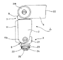
図1〜図7に示すフラッシュ装置1は、本体部2と、取付部3と、発光部4とを備え、本体部2と取付部3は、第1の回動部6によって前後方向(若しくは上下方向)へ回動可能に連結され、本体部2と発光部4は、第2の回動部7によって水平方向及び前後方向(若しくは上下方向)へ回動可能に連結されている。
The
第1の回動部6は、例えば、本体部2の下軸受部と、取付部3の軸受部と、これら両軸受部を水平方向へ貫通する第1の回動軸とから構成され、第1の回動軸を回動中心として前後方向(若しくは上下方向)へ回動可能に構成されている。また、第1の回動軸には、本体部2と取付部3との間に摩擦抵抗を生じさせるばね部材(例えば皿ばね、コイルバネ等)が介在されており、そのばね部材のばね力により、取付部3に対して本体部2を任意の傾斜角度で保持できるようになされている。
The first rotating
第2の回動部7は、発光部4を水平方向へ回動させる水平回動部と、発光部4を上下方向(前後方向)へ回動させる上下回動部とから構成されている。水平回動部は、本体部2の上部に設けた上回動軸部と、本体部2と発光部4との間に介在される連結部材9に設けられ且つ前記上回動軸部を上下方向に貫通する水平動軸部とからなり、上回動軸部を回動中心として発光部4が水平方向へ回動可能とされている。なお、本体部2に軸受穴を設け、連結部材9に回動軸部を設けて、水平方向へ回動可能に構成してもよいことは勿論である。
The
また、上下回動部は、連結部材9に設けた上下動軸受部と、発光部4に設けた回動軸部と、これら上下動軸受部及び回動軸部を水平方向に貫通する第2の回動軸とからなり、第2の回動軸を回動中心として前後方向(上下方向)へ回動可能に構成されている。これら水平回動部と上下回動部を第2の回動部が備えることにより、発光部4が本体部2に対して水平方向及び前後方向へそれぞれ相対的に回動することができる。その結果、発光部4の第2の回動部と反対側の発光面を、略半球状に球面移動させることができる。
The vertical rotation portion includes a vertical movement bearing portion provided in the connecting member 9, a rotation shaft portion provided in the
フラッシュ装置1の本体部2は、内部に空間が設けられた略直方体状の筐体を備えており、その内部空間には、図示しないが、各種の電子部品が実装された配線基板、バッテリー電源、各種の電子部品や機械部品等が収納されている。
The
本体部2の背面には、略四角形に突出する膨出部11が設けられている。図2に示すように、膨出部11の上部には、被写体までの距離やズーム倍率等を表示するための液晶ディスプレイ(LCD)等からなる表示パネル12が設けられている。この表示パネル12の下部には、モード切り換えスイッチ14、電源ボタン15、その他の操作ボタン(図示しない)等が設けられている。モード切り換えスイッチ14は、フラッシュ装置1の機能を切り換えるためのもので、その機能モードとしては、例えば、装着された撮像装置のシャッタボタンを押すと発光部4から光を放射するシンクロモードや、カメラ本体に設けられているフラッシュ装置等の他のフラッシュ装置から放射される光に同調させて発光部4から光を放射するスレーブモード等を挙げることができる。
On the back surface of the
本体部2の下端部には、下面から正面にかけて略四角形の切欠き16が設けられており、この切欠き16を設けることによって一対の突出片17a,17bが形成されている。本体部2の一対の突出片17a,17bには、第1の回動部6の一部を構成する下軸受部が設けられている。
A substantially
本実施例では、本体部2の上下方向への回動動作は、図9及び図10に示すように、本体部2が取付部3に対して略直立して上方に向いた状態(図9A〜F等を参照)から正面側に傾いて斜め上方に向いた状態(図10A〜F等を参照)となるまでの略30度の角度範囲内で回動可能である。そして、この範囲内において、本体部2は取付部3に対して任意の位置で固定可能とされている。
In the present embodiment, as shown in FIGS. 9 and 10, the
取付部3は、本体部2の切欠き16内に配置される取付部材21と、取付部材21の下面において下方へ突出するように固定された固定ねじ22と、固定ねじ22に螺合された円盤状の締付リング23と、固定ねじ22の下端部に固定された平板状の固定板24等から構成されている。取付部3の取付部材21には、図示しないが、第1の回動部6の一部を構成する軸受穴が設けられている。この取付部3は、撮像装置等に設けられている被取付部の一具体例を示すアクセサリーシューに取付可能な構成とされている。即ち、締付リング23と固定板24とでアクセサリーシューの上面片を狭持することにより、取付部3がアクセサリーシューに取り付けられるようになっている。また、取付部3の固定板24の下面には、フラッシュ装置1を撮像装置に電気的に接続するための接続端子25が設けられている。
The
フラッシュ装置1の発光部4は、正面及び背面に開口された略長方形の枠体を備え、背面の開口部が連結部材9に対向されている。発光部4の両側面の背面側には、円形に突出する一対の突出片31a,31bが設けられており、これら一対の突出片28a,28bには、図示しないが、第2の回動部7の上下回動部の一部を構成する回動軸部が設けられている。
The
図1等に示すように、発光部4の正面の開口部には、フレネルレンズ32が取り付けられている。このフレネルレンズ32の後方である発光部4の内部には、発光手段が設けられている。この発光手段は、光源としてのキセノン管33と、このキセノン管33の後方に位置する反射鏡34等からなっている。これらキセノン管33及び反射鏡34等からなる発光手段から放射される光は、フルネルレンズ32によって拡散されて発光部4の外部へ放射される。
As shown in FIG. 1 and the like, a
キセノン管33は、高圧キセノンガスが封入された円筒状のランプであり、発光部4の内面に設けられた図示しない支持部材によって固定されている。また、反射鏡34は、断面形状が光軸に対して略楕円形となるように構成されている。この反射鏡34は、照射範囲変更手段としての反射鏡駆動部36によって、キセノン管33に対して接近及び離反する方向に移動可能とされている。これにより、発光手段から放射される光の放射角度を変更することができ、被写体等に照射する光の照射範囲を調節することができる。
The
反射鏡34を移動させる反射鏡駆動部36は、例えば、モータと、このモータの回転軸に嵌合されたギアと、ギアに噛み合う送りねじ等により構成することができる。この場合、反射鏡34に送りねじに螺合する雌ねじ部を設け、モータの回転をギアを介して送りねじに伝え、送りねじを回転させるようにする。これにより、固定されたキセノン管33に対して、雌ねじ部が設けられた反射鏡34を相対的に移動させて所望の位置に移動させることができる。
The reflecting
本実施例では、発光部4の上下方向への回動動作は、図9に示すように、発光部4が本体部2に対して略垂直となって前方に突き出した状態(図9Aを参照)から上方へ略90度回動して、発光部4が本体部2に対して略直立して上方に向いた状態(図9Dを参照)を経て、更に略30度後方へ回動して発光部4が背面側に傾いた状態(図9Fを参照)となるまでの略120度の角度範囲内で回動可能である。そして、この範囲内において、発光部4は本体部2に対して任意の位置で固定可能とされている。
In the present embodiment, the vertical movement of the
このような構成を有するフラッシュ装置1によれば、本体部2が上下方向(前後方向)に回動可能であると共に、発光部4が本体部3に対して水平方向及び上下方向(前後方向)に回動可能であるため、発光部4の発光面を、略半球状に球面移動させることができる。その結果、例えば、発光部4が前方に変位した状態で発光面を前方に向けること(図8及び図10Cを参照)や、発光面を斜め下方に向けこと(図10Aを参照)ができると共に、図10Aに示す状態から発光部4を本体部3の上面に対して水平方向に回動させて、図11に示すような、発光部4が傾いた状態で発光面を側方に向けることもできる。
According to the
本実施例では、照射範囲変更手段として反射鏡駆動部36を用い、キセノン管33に対して反射鏡34を接近及び離反するように移動させる構成としたが、本発明のフラッシュ装置に係る照射範囲変更手段としては、これに限定されるものではなく、反射鏡を固定し、その反射鏡に対してキセノン管33を接近及び離反するように移動させる構成としてもよく、更に、キセノン管33及び反射鏡34を相対的に移動させる構成とすることもできるものである。
In this embodiment, the reflecting
また、本実施例では、本体部2の上下方向への回動動作を、取付部3に対して略直立して上方に向いた状態から正面側に傾いて斜め上方に向いた状態となるまでの略30度の角度範囲内で回動可能に構成すると共に、発光部4の上下方向への回動動作を、本体部2に対して略垂直となって前方に突き出した状態から背面側に傾いた状態となるまでの略120度の角度範囲内で回動可能に構成したが、本体部2及び発光部4の回動動作としては、これらに限定されるものではなく、例えば、45度、90度等、その傾ける角度を所望の角度に設定することができるものである。なお、本体部2においては、正面側に回動させる構成に限定されるものではなく、背面側に回動可能な構成とすることもできるものである。
Further, in this embodiment, the pivoting operation of the
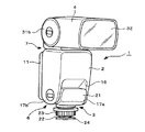
図12は、前述したような構成を有するフラッシュ装置1を装着した本発明の撮像装置の第1の実施の例を示す電子スチルカメラ51の図である。この電子スチルカメラ51は、撮像装置本体の一具体例を示すカメラ本体52を備えている。
FIG. 12 is a diagram of an
カメラ本体52は、内部に空間が設けられた横長の筐体からなるカメラケース53を備えている。カメラケース53の内部空間には、図示しないが、各種の電子部品が実装された配線基板、バッテリー電源、記憶装置、その他各種の電子部品や機械部品、装置等が収納されている。カメラケース53の正面の略中央部には、レンズ装置55が配置されている。このレンズ装置55の先端部には、望遠や広角等の機能を付加するためのコンバージョンレンズ56が着脱自在に取り付けられている。また、レンズ装置55の光軸の後方には、撮像手段の一具体例を示すCCD(固体撮像素子)が配置されている。
The
カメラケース53の上面には、このカメラケース53に一体的に設けられているフラッシュ装置58が設けられている。このフラッシュ装置58は、フラッシュを使用して撮影するときに立ち上がり、これにより、図示しないフラッシュ発光部が露出されるようになっている。更にカメラケース53には、図示しないが、電源ボタン、メニューボタン、表示装置の一具体例を示す液晶ディスプレイ(LCD)、電子ビューファインダ等が設けられている。
A
また、カメラケース53の正面の右側部(図12において、電子スチルカメラ51に向かって左側)には、このカメラケース53を把持するための把持部53aが設けられている。カメラケース53の把持部53aは、その全体が前側に突出されていて、片手で握り易い形状とされている。この把持部53aの上面には、被写体を撮影するためのシャッタボタン59と、フラッシュ接続回路の接続端子を有する被取付部の一具体例を示すアクセサリーシュー(図示しない)が配置されており、そのアクセサリーシューにフラッシュ装置1が着脱自在に取り付けられている。この際、フラッシュ装置1の固定板24に設けた接続端子25が、電子スチルカメラ51のアクセサリーシューの接続端子に当接されて、フラッシュ装置1と電子スチルカメラ51の互いの電気回路が電気的に接続される。
Further, a
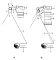
このようなフラッシュ装置1を装着した電子スチルカメラ51によってフラッシュ撮影を行う状態の例を図13A,13Bに示す。図13Aには、電子スチルカメラ51にコンバージョンレンズ56を取り付けないで撮影を行う状態が示されている。この場合、フラッシュ装置1の姿勢を、本体部2が電子スチルカメラ51の上面に対して略垂直になると共に発光部4が電子スチルカメラ51のレンズ装置の光軸に平行となるような姿勢(図9Aに示す姿勢)にする。これにより、フラッシュ装置1の発光部4から放射される光は、光線L1で示すように被写体Xに照射されるため、所望の照射範囲(被写体Xの上半身)に確実に光を照射することができ、綺麗な画像を撮影することができる。
An example of a state in which flash photography is performed by the electronic still
図13Bには、電子スチルカメラ51にコンバージョンレンズ56を取り付けて撮影を行う状態が示されている。この場合、フラッシュ装置1の姿勢を破線で示すような図13Aと同じ姿勢にすると、発光部4から放射される光は光線L1´で示すように被写体Xに照射されるため、所望の照射範囲(被写体Xの上半身)の一部Yに光を照射することができず、撮影画像にケラレが生じてしまう。そこで、フラッシュ装置1の本体部2を被写体X側に傾くように回動させると共に、発光部4を電子スチルカメラ51のレンズ装置55の光軸に平行となるように回動させて、フラッシュ装置1の姿勢を実線で示すような発光部4が被写体側に近づいた姿勢(図10Cに示す姿勢)にする。これにより、発光部4から放射される光は、光線L2で示すように被写体Xに照射されるため、所望の照射範囲(被写体Xの上半身)に確実に光を照射することができ、綺麗な画像を撮影することができる。
FIG. 13B shows a state where the
図14は、前述したような構成及び作用を有するフラッシュ装置1及びそのフラッシュ装置1が装着された電子スチルカメラ51の概略構成の第1の実施の例を示すブロック図である。
FIG. 14 is a block diagram showing a first example of a schematic configuration of a
フラッシュ装置1は、発光部4に発光手段であるキセノン管33及び反射鏡34と、反射鏡34をキセノン管33に対して接近及び離反する方向に移動させる照射範囲変更手段の一具体例を示す反射鏡駆動部36等を備えると共に、本体部2にその本体部2の傾きを検出してその検出信号を出力する傾き検出手段の一具体例を示す角度検出器37等を備えて構成されている。角度検出器37は、例えば、ジャイロセンサを用いることができ、例えば、重力方向に対する本体部2の傾きに基づいてその傾斜角度を検出することができる。反射鏡駆動部36及び角度検出器37には、フラッシュ装置1の取付部3に設けられた接続端子25が接続されている。
The
電子スチルカメラ51は、ズームレンズ61を有するレンズ装置55と、制御装置の中心的役割をなす画像記録/再生回路部70と、画像記録/再生回路部70を駆動するためのプログラムメモリやデータメモリその他のRAMやROM等を有する内蔵メモリ71と、撮影された画像等を所定の信号に処理する画像信号処理部72と、撮影された画像等を表示する表示装置73と、記憶容量を拡大する外部メモリ74と、ズームレンズを駆動制御すると共に被写体に向けて放射される光の照射範囲を調節する制御信号を出力する照射範囲算出手段の一具体例を示す制御部75等を備えて構成されている。
The electronic still
画像記録/再生回路部70は、例えば、マイクロコンピュータ(CPU)を有する演算回路等を備えて構成されている。この画像記録/再生回路部70に、内蔵メモリ71と画像信号処理部72と制御部75とモニタ駆動部76と2つのインタフェース(I/F)81,82とが接続されている。画像信号処理部72は、レンズ装置55に取り付けられた撮像手段の一具体例を示すCCD76に増幅器77を介して接続されており、所定の映像信号に処理された信号が画像記録/再生回路部70に入力される。
The image recording / reproducing circuit unit 70 includes, for example, an arithmetic circuit having a microcomputer (CPU). A built-in
表示装置73は、モニタ駆動部78を介して画像記録/再生回路部70に接続されている。また、第1のインタフェース(I/F)81にはコネクタ85が接続されており、このコネクタ85に外部メモリ74が着脱自在に接続可能とされている。第2のインタフェース(I/F)82には、カメラ本体52に設けられた接続端子86が接続されている。
The
制御部75には、シャッタボタン59やメニューボタン等の操作部87とズームレンズ61を駆動制御するズーム駆動部88が接続されていると共に、ズームレンズ61の位置及び被写体までの距離を検出する距離測定手段の一具体例を示す位置検出センサ89が接続されている。更に、制御部75には、第3のインタフェース(I/F)83を介して接続端子90が接続されており、この接続端子90にフラッシュ装置1の接続端子25が着脱自在に接続可能とされている。
The
かくして、被写体の像がレンズ装置55のレンズ系に入力されてCCD76の結像面に結像されると、その画像信号が増幅器77を介して画像信号処理部72に入力される。この画像信号処理部72で所定の映像信号に処理された信号が画像記録/再生回路部70に入力される。これにより、画像記録/再生回路部70から被写体の像に対応した信号がモニタ駆動部78、内蔵メモリ71若しくは外部メモリ74に出力される。その結果、モニタ駆動部78を介して表示装置73に被写体の像に対応した画像が表示され、或いは、必要により情報信号として内蔵メモリ71若しくは外部メモリ74に記録される。
Thus, when the image of the subject is input to the lens system of the
このような撮影状態において、フラッシュ装置1の発光部4がレンズ装置55の光軸に略平行な状態にして、フラッシュ装置1の本体部2を前方に回動させると、角度検出器37が本体部2の傾きを検出し、その検出信号を接続端子90及び第3のインタフェース(I/F)83を介して制御部75に出力する。また、位置検出センサ89が被写体までの距離を検出し、その検出信号を制御部75に出力する。これら検出信号を受けて制御部75では、所定の演算処理を実行して、被写体に向けて放射される光の照射範囲を制御する制御信号を第3のインタフェース(I/F)83、電子スチルカメラ51の接続端子90及びフラッシュ装置1の接続端子25を介して発光部4の反射鏡駆動部36に出力する。この反射鏡駆動部36では、制御部75からの制御信号に基づいて、反射鏡34をキセノン管33に対して接近又は離反する方向に所定量だけ移動させ、発光手段から放射される光の放射角度を変更する。これにより、フラッシュ装置1の発光部4から被写体にむけて放射される光の照射範囲を好適となるように調節することができ、所望の画角に確実に光を照射させて綺麗な画像を得ることができる。
In such a photographing state, when the
図15は、前述したフラッシュ装置1に装着することにより、フラッシュ装置1を載置面に載置することができる支持台の一具体例を示すスタンド101を示すものである。このスタンド101は、略四角形の板体からなり、上面にフラッシュ装置1の取付部3が着脱自在に取付可能なアクセサリーシュー102が設けられている。
FIG. 15 shows a
アクセサリーシュー102は、スタンド101の一辺の略中央部に配置されており、略四角形に形成された収納部102aと、この収納部102aの底面と対向すると共にスタンド101の上面に連続する上面片102b等からなっている。このアクセサリーシュー102の収納部102aにフラッシュ装置1の取付部3に設けた固定板22が挿入され、上面片102bがフラッシュ装置1の締付リング23と固定板24によって狭持されることにより、スタンド101がフラッシュ装置1に装着されるようになっている。
The
なお、スタンド101をフラッシュ装置1に装着して使用する場合、フラッシュ装置1の機能モードをスレーブモードにする。これにより、例えば、カメラ本体に本来設けられているフラッシュ装置と本フラッシュ装置1との2台のフラッシュ装置を連動させて発光させるフラッシュ撮影を行うことができる。即ち、フラッシュ装置1の取付部3の取付部材21には、図示しない光センサが設けられており、この光センサがカメラ本体のフラッシュ装置から放射された光を検出し、その検出光量に応じた光がフラッシュ装置1の発光部4から放射されるようになっている。
Note that when the
このようなスタンド101をフラッシュ装置1に装着することにより、フラッシュ装置1を載置面に載置することができ、被写体に直接的又は間接的に照射する光の角度や、フラッシュ装置1の被写体までの距離を自由に設定してフラッシュ撮影を行うことができる。例えば、図16に示すように、フラッシュ装置1の姿勢を、発光部4の発光面が斜め下方に向くような姿勢にすることにより、被写体に下からのバウンズ光を照射する撮影を簡単に行うことができる。
By attaching such a
以上説明したように、本発明のフラッシュ装置によれば、レンズ装置が被写体側に大きく突出した撮像装置に装着してフラッシュ撮影を行う場合、本体部を被写体側に傾けるように回動させて、発光部をレンズ装置の近傍に変位させることができるため、発光部から放射される光の一部がレンズ装置によって遮られる心配がなく、撮影画像にケラレが生じることを防止することができる。 As described above, according to the flash device of the present invention, when the lens device is attached to an imaging device that protrudes largely toward the subject side and flash photography is performed, the main body is tilted toward the subject side, Since the light emitting unit can be displaced in the vicinity of the lens device, there is no fear that a part of the light emitted from the light emitting unit is blocked by the lens device, and it is possible to prevent the vignetting from occurring in the captured image.
また、本発明の撮像装置によれば、フラッシュ装置の傾き検出手段から出力される検出信号と、距離測定手段から出力される検出信号にもとづいて、フラッシュ装置の発光部から放射される光の照射範囲を調節する制御信号を照射範囲算出手段により出力するため、この制御信号を受けたフラッシュ装置が、キセノン管又は反射鏡を相対的に移動して光を所望の照射範囲に確実に照射させることができ、綺麗な画像を撮影することができる。 Further, according to the imaging apparatus of the present invention, irradiation of light emitted from the light emitting unit of the flash device based on the detection signal output from the tilt detection unit of the flash device and the detection signal output from the distance measurement unit. Since the control signal for adjusting the range is output by the irradiation range calculation means, the flash device that has received this control signal moves the xenon tube or the reflector relatively to reliably irradiate the desired irradiation range. You can shoot beautiful images.
本発明は、前述しかつ図面に示した実施の形態に限定されるものではなく、その要旨を逸脱しない範囲内で種々の変形実施が可能である。例えば、前記実施例においては、撮像装置として電子スチルカメラを適用した例について説明したが、スチルカメラ、ビデオカメラその他の撮像装置にも適用できるものである。 The present invention is not limited to the embodiment described above and shown in the drawings, and various modifications can be made without departing from the scope of the invention. For example, in the above-described embodiment, an example in which an electronic still camera is applied as an imaging device has been described. However, the present invention can also be applied to a still camera, a video camera, and other imaging devices.
1…フラッシュ装置、 2…本体部、 3…取付部、 4…発光部、 6…第1の回動部、 7…第2の回動部、 9…連結部材、 21…取付部材、 22…固定ねじ、 23…締付リング、 24…固定板、 25…接続端子、 32…フレネルレンズ、 33…キセノン管(発光手段)、 34…反射鏡(発光手段)、 36…反射鏡駆動部(照射範囲変更手段)、 37…角度検出器(傾き検出手段)、 51…電子スチルカメラ(撮像装置)、 52…カメラ本体、 55…レンズ装置、 56…コンバージョンレンズ、 70…画像記録/再生回路、 75…制御部(照射範囲算出手段)、 89…位置検出センサ(距離検出手段)、 90…接続端子
DESCRIPTION OF
Claims (5)
前記取付部に対して第1の回動部を介して前後方向へ回動可能に支持された本体部と、
前記本体部に対して第2の回動部を介して前後方向又は上下方向へ回動可能に支持されると共に被写体に対して直接的又は間接的に光を放射する発光手段を有する発光部と、を設けたことを特徴とするフラッシュ装置。 An attachment part that can be detachably attached to a to-be-attached part provided in the imaging device;
A main body supported so as to be pivotable in the front-rear direction with respect to the mounting part via a first pivot part;
A light-emitting unit that is supported to be rotatable in the front-rear direction or the vertical direction with respect to the main body unit via a second rotation unit, and that emits light directly or indirectly to the subject; And a flash device.
前記撮像装置から供給される制御信号に基づきキセノン管又は反射鏡を相対的に移動して被写体に照射される光の照射範囲を変更可能な照射範囲変更手段と、を設けたことを特徴とする請求項1記載のフラッシュ装置。 Inclination detecting means for detecting the inclination of the main body and outputting the detection signal;
Irradiation range changing means capable of changing the irradiation range of the light irradiated to the subject by relatively moving the xenon tube or the reflecting mirror based on the control signal supplied from the imaging device. The flash device according to claim 1.
前記レンズ装置から入力される被写体の像を撮像すると共にその撮像信号を出力する撮像手段と、
前記被写体に対して直接的又は間接的に光を放射するフラッシュ装置と、
前記フラッシュ装置が着脱可能に装着される被取付部と、
を備えた撮像装置において、
前記フラッシュ装置は、前記被取付部に対して着脱自在に取付可能な取付部と、前記取付部に対して第1の回動部を介して前後方向へ回動可能に支持された本体部と、前記本体部に対して第2の回動部を介して前後方向又は上下方向へ回動可能に支持されると共に被写体に対向される発光手段を有する発光部と、を設けたことを特徴とする撮像装置。 A lens device through which the light of the subject passes,
An image pickup means for picking up an image of a subject input from the lens device and outputting the image pickup signal;
A flash device that emits light directly or indirectly to the subject;
A mounted portion to which the flash device is detachably mounted;
In an imaging device comprising:
The flash device includes an attachment portion that can be detachably attached to the attachment portion, and a main body portion that is supported to be rotatable in the front-rear direction with respect to the attachment portion via a first rotation portion. And a light-emitting unit that is supported to be rotatable in the front-rear direction or the vertical direction with respect to the main body unit via a second rotation unit and that has a light-emitting unit that faces the subject. Imaging device.
前記本体部の傾きを検出してその検出信号を出力する傾き検出手段と、
前記距離検出手段からの検出信号と前記傾き検出手段からの検出信号に基づき前記発光手段から前記被写体に向けて放射される光の照射範囲が好適となるように発光部を制御するための制御信号を出力する照射範囲算出手段と、
前記発光制御手段からの制御信号に基づきキセノン管又は反射鏡を相対的に移動して被写体に照射される光の照射範囲を変更可能な照射範囲変更手段と、を設けたことを特徴とする請求項4記載の撮像装置。 Distance measuring means for detecting a distance to the subject and outputting a detection signal;
Inclination detecting means for detecting the inclination of the main body and outputting the detection signal;
A control signal for controlling the light emitting unit so that the irradiation range of the light emitted from the light emitting means toward the subject is suitable based on the detection signal from the distance detecting means and the detection signal from the inclination detecting means. Irradiation range calculation means for outputting
An irradiation range changing unit capable of changing an irradiation range of light irradiated to a subject by relatively moving a xenon tube or a reflecting mirror based on a control signal from the light emission control unit. Item 5. The imaging device according to Item 4.
Priority Applications (2)
| Application Number | Priority Date | Filing Date | Title |
|---|---|---|---|
| JP2005248146A JP2007065081A (en) | 2005-08-29 | 2005-08-29 | Flash unit and imaging device |
| US11/508,296 US7668448B2 (en) | 2005-08-29 | 2006-08-23 | Flash apparatus and imaging apparatus |
Applications Claiming Priority (1)
| Application Number | Priority Date | Filing Date | Title |
|---|---|---|---|
| JP2005248146A JP2007065081A (en) | 2005-08-29 | 2005-08-29 | Flash unit and imaging device |
Publications (2)
| Publication Number | Publication Date |
|---|---|
| JP2007065081A true JP2007065081A (en) | 2007-03-15 |
| JP2007065081A5 JP2007065081A5 (en) | 2008-07-24 |
Family
ID=37804237
Family Applications (1)
| Application Number | Title | Priority Date | Filing Date |
|---|---|---|---|
| JP2005248146A Pending JP2007065081A (en) | 2005-08-29 | 2005-08-29 | Flash unit and imaging device |
Country Status (2)
| Country | Link |
|---|---|
| US (1) | US7668448B2 (en) |
| JP (1) | JP2007065081A (en) |
Cited By (6)
| Publication number | Priority date | Publication date | Assignee | Title |
|---|---|---|---|---|
| WO2013051217A1 (en) * | 2011-10-07 | 2013-04-11 | パナソニック株式会社 | Flash device and image capture device provided with flash device |
| WO2014043273A1 (en) * | 2012-09-14 | 2014-03-20 | ExpoImaging, Inc. | Light focusing device |
| US8891954B1 (en) | 2013-06-19 | 2014-11-18 | ExpoImaging, Inc. | Light focusing device |
| CN104246602A (en) * | 2012-04-25 | 2014-12-24 | 松下知识产权经营株式会社 | Strobe device and imaging device equipped with strobe device |
| US9158181B2 (en) | 2012-09-14 | 2015-10-13 | ExpoImaging, Inc. | Light focusing device |
| US9158180B2 (en) | 2012-09-14 | 2015-10-13 | ExpoImaging, Inc. | Light focusing device |
Families Citing this family (12)
| Publication number | Priority date | Publication date | Assignee | Title |
|---|---|---|---|---|
| US20080260371A1 (en) * | 2007-04-20 | 2008-10-23 | Jerry Curtis Hughes | Patent application for an apparatus and method of positioning a flash on a camera |
| CN101373308B (en) * | 2007-08-23 | 2011-02-02 | 鸿富锦精密工业(深圳)有限公司 | Image viewfinding device and flash lamp control method thereof |
| JP2013178354A (en) * | 2012-02-28 | 2013-09-09 | Panasonic Corp | Stroboscopic device and imaging apparatus including stroboscopic device |
| JPWO2013157224A1 (en) * | 2012-04-17 | 2015-12-21 | パナソニックIpマネジメント株式会社 | Strobe device irradiation direction angle adjustment method, strobe device, and image pickup device equipped with strobe device |
| US8736710B2 (en) * | 2012-05-24 | 2014-05-27 | International Business Machines Corporation | Automatic exposure control for flash photography |
| JP2014038269A (en) * | 2012-08-20 | 2014-02-27 | Panasonic Corp | Stroboscopic device, imaging apparatus and image processing method |
| JP2014038267A (en) * | 2012-08-20 | 2014-02-27 | Panasonic Corp | Stroboscopic device and imaging apparatus |
| JP2014153669A (en) * | 2013-02-13 | 2014-08-25 | Sony Corp | Imaging device, imaging method, and light-emitting device |
| JP1569177S (en) * | 2016-07-13 | 2017-02-13 | ||
| JP1631554S (en) * | 2018-05-15 | 2019-05-20 | ||
| USD927584S1 (en) * | 2019-07-03 | 2021-08-10 | Yueqing Originality Photography Equipment Co., Ltd. | Flashlight |
| JP2022006845A (en) * | 2020-06-25 | 2022-01-13 | キヤノン株式会社 | Accessory shoe device, electronic device, shoe device, and accessory device |
Citations (7)
| Publication number | Priority date | Publication date | Assignee | Title |
|---|---|---|---|---|
| JPS5779827A (en) * | 1980-10-30 | 1982-05-19 | Sato Shigeru | Gut hooking apparatus during bail arm opening |
| JPS63204238A (en) * | 1987-02-20 | 1988-08-23 | Nikon Corp | Electronic flashing device |
| JPH01304440A (en) * | 1988-06-02 | 1989-12-08 | Olympus Optical Co Ltd | Bouncing storoboscopic device |
| JPH0367321A (en) * | 1989-08-05 | 1991-03-22 | Mitsubishi Electric Corp | Rotary encoder |
| JPH0923361A (en) * | 1995-07-07 | 1997-01-21 | Canon Inc | Image pickup device |
| JPH09281560A (en) * | 1996-04-18 | 1997-10-31 | West Electric Co Ltd | Irradiation angle variable electronic flash device |
| JP2002072301A (en) * | 2000-08-24 | 2002-03-12 | Canon Inc | Stroboscopic device and strobe light photographing system |
Family Cites Families (9)
| Publication number | Priority date | Publication date | Assignee | Title |
|---|---|---|---|---|
| JPS5223932A (en) * | 1975-08-19 | 1977-02-23 | West Electric Co Ltd | Electronic flash device for photography |
| US4238150A (en) * | 1979-01-04 | 1980-12-09 | Rollei Of America, Inc. | Rotatable electronic flash device with automatic light sensor tracking |
| JPS59140428A (en) * | 1983-01-31 | 1984-08-11 | Canon Inc | Flash device |
| JPS59149126U (en) * | 1983-03-28 | 1984-10-05 | キヤノン株式会社 | flash device |
| JPH0740724B2 (en) | 1985-09-30 | 1995-05-01 | ソニー株式会社 | Video camera with lighting |
| DE19722397C2 (en) * | 1996-05-30 | 2001-04-19 | West Electric Co | Strobe light device with variable emission angle and control method for this |
| US5839006A (en) * | 1996-10-30 | 1998-11-17 | Beckerman; Arnold Edward | Apparatus and method for directing light from a swivel flash head |
| JPH11174535A (en) | 1997-12-09 | 1999-07-02 | Olympus Optical Co Ltd | Stroboscopic device and camera system capable of electronic image pickup |
| JP4524891B2 (en) * | 2000-09-11 | 2010-08-18 | 株式会社ニコン | External flash device |
-
2005
- 2005-08-29 JP JP2005248146A patent/JP2007065081A/en active Pending
-
2006
- 2006-08-23 US US11/508,296 patent/US7668448B2/en not_active Expired - Fee Related
Patent Citations (7)
| Publication number | Priority date | Publication date | Assignee | Title |
|---|---|---|---|---|
| JPS5779827A (en) * | 1980-10-30 | 1982-05-19 | Sato Shigeru | Gut hooking apparatus during bail arm opening |
| JPS63204238A (en) * | 1987-02-20 | 1988-08-23 | Nikon Corp | Electronic flashing device |
| JPH01304440A (en) * | 1988-06-02 | 1989-12-08 | Olympus Optical Co Ltd | Bouncing storoboscopic device |
| JPH0367321A (en) * | 1989-08-05 | 1991-03-22 | Mitsubishi Electric Corp | Rotary encoder |
| JPH0923361A (en) * | 1995-07-07 | 1997-01-21 | Canon Inc | Image pickup device |
| JPH09281560A (en) * | 1996-04-18 | 1997-10-31 | West Electric Co Ltd | Irradiation angle variable electronic flash device |
| JP2002072301A (en) * | 2000-08-24 | 2002-03-12 | Canon Inc | Stroboscopic device and strobe light photographing system |
Cited By (8)
| Publication number | Priority date | Publication date | Assignee | Title |
|---|---|---|---|---|
| WO2013051217A1 (en) * | 2011-10-07 | 2013-04-11 | パナソニック株式会社 | Flash device and image capture device provided with flash device |
| JP2013092747A (en) * | 2011-10-07 | 2013-05-16 | Panasonic Corp | Stroboscopic device and imaging apparatus equipped with stroboscopic device |
| US9383627B2 (en) | 2011-10-07 | 2016-07-05 | Panasonic Intellectual Property Management Co., Ltd. | Flash device and image capture device provided with flash device |
| CN104246602A (en) * | 2012-04-25 | 2014-12-24 | 松下知识产权经营株式会社 | Strobe device and imaging device equipped with strobe device |
| WO2014043273A1 (en) * | 2012-09-14 | 2014-03-20 | ExpoImaging, Inc. | Light focusing device |
| US9158181B2 (en) | 2012-09-14 | 2015-10-13 | ExpoImaging, Inc. | Light focusing device |
| US9158180B2 (en) | 2012-09-14 | 2015-10-13 | ExpoImaging, Inc. | Light focusing device |
| US8891954B1 (en) | 2013-06-19 | 2014-11-18 | ExpoImaging, Inc. | Light focusing device |
Also Published As
| Publication number | Publication date |
|---|---|
| US7668448B2 (en) | 2010-02-23 |
| US20070047944A1 (en) | 2007-03-01 |
Similar Documents
| Publication | Publication Date | Title |
|---|---|---|
| JP2007065081A (en) | Flash unit and imaging device | |
| US9876961B2 (en) | Lighting apparatus including first housing and second housing that can rotate with respect to the first housing and control method | |
| JP2001290198A (en) | Projection type finder for camera | |
| JP2011170014A (en) | Stroboscopic device | |
| WO2014030331A1 (en) | Strobe device and imaging device provided with strobe device | |
| JP2015001669A (en) | Imaging device, camera system and control method | |
| JPWO2014030329A1 (en) | Strobe device and imaging device equipped with the strobe device | |
| JP6584129B2 (en) | Lighting device | |
| JP2010191270A (en) | Photographing device | |
| WO2012077252A1 (en) | Imaging device | |
| JP2010074328A (en) | Electronic device | |
| JP2009219019A (en) | Imaging device and adapter | |
| JP2015194576A (en) | Illumination device | |
| JP2006350252A (en) | Imaging apparatus and tilt device | |
| JPWO2006054440A1 (en) | Camera auxiliary light device | |
| JP5195091B2 (en) | Imaging device | |
| JP2009192606A (en) | Imaging apparatus | |
| JP2004080180A (en) | Cradle for mount on digital camera, and digital camera | |
| JP5252851B2 (en) | Imaging device | |
| KR101398472B1 (en) | Digital camera | |
| JP6736865B2 (en) | Electronics | |
| JPH0418533A (en) | Short-distance photography device of camera | |
| JP2010081046A (en) | Imaging device | |
| WO2012077251A1 (en) | Imaging apparatus | |
| JP2016109824A (en) | Imaging system, illumination device and imaging device, and control method of the same |
Legal Events
| Date | Code | Title | Description |
|---|---|---|---|
| A521 | Request for written amendment filed |
Free format text: JAPANESE INTERMEDIATE CODE: A523 Effective date: 20080611 |
|
| A621 | Written request for application examination |
Free format text: JAPANESE INTERMEDIATE CODE: A621 Effective date: 20080611 |
|
| A977 | Report on retrieval |
Free format text: JAPANESE INTERMEDIATE CODE: A971007 Effective date: 20100712 |
|
| A131 | Notification of reasons for refusal |
Free format text: JAPANESE INTERMEDIATE CODE: A131 Effective date: 20100727 |
|
| A521 | Request for written amendment filed |
Free format text: JAPANESE INTERMEDIATE CODE: A523 Effective date: 20100921 |
|
| A131 | Notification of reasons for refusal |
Free format text: JAPANESE INTERMEDIATE CODE: A131 Effective date: 20101116 |
|
| A521 | Request for written amendment filed |
Free format text: JAPANESE INTERMEDIATE CODE: A523 Effective date: 20101229 |
|
| A02 | Decision of refusal |
Free format text: JAPANESE INTERMEDIATE CODE: A02 Effective date: 20110315 |