JP2007057772A - Developing system - Google Patents

Developing system Download PDF

Info

Publication number
JP2007057772A
JP2007057772A JP2005242370A JP2005242370A JP2007057772A JP 2007057772 A JP2007057772 A JP 2007057772A JP 2005242370 A JP2005242370 A JP 2005242370A JP 2005242370 A JP2005242370 A JP 2005242370A JP 2007057772 A JP2007057772 A JP 2007057772A
Authority
JP
Japan
Prior art keywords
developer
roller
paper
unit
developing
Prior art date
Legal status (The legal status is an assumption and is not a legal conclusion. Google has not performed a legal analysis and makes no representation as to the accuracy of the status listed.)
Pending
Application number
JP2005242370A
Other languages
Japanese (ja)
Other versions
JP2007057772A5 (en
Inventor
Koichi Kamijo
浩一 上條
Takeshi Ikuma
健 井熊
Current Assignee (The listed assignees may be inaccurate. Google has not performed a legal analysis and makes no representation or warranty as to the accuracy of the list.)
Seiko Epson Corp
Original Assignee
Seiko Epson Corp
Priority date (The priority date is an assumption and is not a legal conclusion. Google has not performed a legal analysis and makes no representation as to the accuracy of the date listed.)
Filing date
Publication date
Application filed by Seiko Epson Corp filed Critical Seiko Epson Corp
Priority to JP2005242370A priority Critical patent/JP2007057772A/en
Priority to US11/466,711 priority patent/US7561815B2/en
Publication of JP2007057772A publication Critical patent/JP2007057772A/en
Publication of JP2007057772A5 publication Critical patent/JP2007057772A5/ja
Pending legal-status Critical Current

Links

Images

Abstract

<P>PROBLEM TO BE SOLVED: To provide a developing system with which concentration for various kinds of paper can be kept. <P>SOLUTION: The developing system where an image is formed in an image forming part 1 with a developer whose concentration is adjusted by a developer concentration adjusting part 22 is equipped with a developer concentration adjusting control part 40 having: a paper kind input means 45 for inputting the kind of paper; and a controller 43 adjusting the difference of circumferential speed between a developer supply roller 5 and a developing roller 9 according to the kind of paper input by the paper kind input means 45. <P>COPYRIGHT: (C)2007,JPO&INPIT

Description

本発明は、感光体に形成された静電潜像を、キャリア液中にトナー粒子を分散させた現像剤により現像する現像システムに関する。   The present invention relates to a development system that develops an electrostatic latent image formed on a photoreceptor with a developer in which toner particles are dispersed in a carrier liquid.

従来、液体現像剤を使用した電子写真方式現像システムにおいて、キャリア液の量を調整する技術が知られている。具体的には、転写紙の性質に基づいて偏心カム等でスイープローラの液除去力を切り替え、除去すべき量だけ余剰の液体現像剤を除去して液膜を規制する。これにより、感光体ドラムにスイープローラを当接させているので、除去が困難な高粘性高濃度の液体現像剤を容易に除去でき、スイープローラと感光体ドラムとの機械精度の維持が容易となる。
特開2003−91161号公報
Conventionally, a technique for adjusting the amount of carrier liquid in an electrophotographic development system using a liquid developer is known. Specifically, the liquid removal force of the sweep roller is switched with an eccentric cam or the like based on the properties of the transfer paper, and the liquid film is regulated by removing excess liquid developer by an amount to be removed. As a result, since the sweep roller is in contact with the photosensitive drum, it is possible to easily remove the highly viscous and high-concentration liquid developer that is difficult to remove, and it is easy to maintain the mechanical accuracy of the sweep roller and the photosensitive drum. Become.
JP 2003-91161 A

しかしながら、上記従来技術では、表面粗さが粗い転写紙等をセットするときは比較的多くの現像剤を付着させる必要があるので、スイープローラを感光体ドラムから離間させている。この状態では、スイープローラは感光体ドラム上に形成された現像剤薄層から余剰キャリア液を除去しない。一般に表面粗さが粗い転写紙をセットした場合、現像剤のキャリア液の量が多いと、トナー粒子がキャリア液ごと転写紙の繊維内に引っ張られて、所定の濃度が得られなくなる。   However, in the above prior art, when setting a transfer paper or the like having a rough surface, it is necessary to attach a relatively large amount of developer, so that the sweep roller is separated from the photosensitive drum. In this state, the sweep roller does not remove excess carrier liquid from the developer thin layer formed on the photosensitive drum. In general, when a transfer paper having a rough surface is set, if the amount of the carrier liquid of the developer is large, the toner particles are pulled together with the carrier liquid into the fibers of the transfer paper, and a predetermined concentration cannot be obtained.

本発明は上記課題を解決し、様々な紙種に対して濃度を保つことができる現像システムを提供することを目的とする。   SUMMARY OF THE INVENTION An object of the present invention is to solve the above-mentioned problems and to provide a development system capable of maintaining the density for various paper types.

本発明は上記課題を解決するものであって、現像剤を担持する現像ローラと、現像剤を前記現像ローラに供給する現像剤供給ローラと、前記現像ローラに担持した現像剤により顕像を形成する感光体と、前記感光体の顕像を転写する転写手段とを有する画像形成部と、高濃度トナーを貯留したトナータンクと、キャリア液を貯留したキャリア液タンクと、前記トナータンクから高濃度トナーを補給し、前記キャリア液タンクからキャリア液を補給することで現像剤の濃度を調整する現像剤濃度調整槽とを有する現像剤濃度調整部とを備え、前記現像剤濃度調整部で濃度を調整された現像剤により前記画像形成部で画像形成される現像システムにおいて、紙種を入力する紙種入力手段と、前記紙種入力手段が入力した紙種に応じて現像剤供給ローラと現像ローラとの周速差を調整するように制御する制御装置とを有する現像剤濃度調整制御部を備えたことを特徴とする。   The present invention solves the above-described problem, and forms a visible image by a developing roller carrying a developer, a developer supplying roller for supplying the developer to the developing roller, and a developer carried on the developing roller. An image forming unit having a transfer member for transferring a visible image of the photosensitive member, a toner tank storing high-concentration toner, a carrier liquid tank storing carrier liquid, and a high concentration from the toner tank. A developer concentration adjusting unit having a developer concentration adjusting tank that adjusts the concentration of the developer by replenishing toner and replenishing the carrier liquid from the carrier liquid tank, and the developer concentration adjusting unit In the developing system in which the image forming unit forms an image with the adjusted developer, a paper type input unit that inputs a paper type, and a developer supply roller according to the paper type input by the paper type input unit. Characterized by comprising a developer density adjustment control unit and a control unit for controlling so as to adjust the peripheral speed difference between La and the developing roller.

また、前記制御装置は、前記紙種入力手段がデフォルト紙より粗い紙と入力した場合、前記現像剤供給ローラの周速を前記現像ローラの周速よりも上げるように制御することを特徴とする。   Further, the control device controls the peripheral speed of the developer supply roller to be higher than the peripheral speed of the developing roller when the paper type input unit inputs paper that is coarser than the default paper. .

また、前記制御装置は、前記紙種入力手段がデフォルト紙より粗い紙と入力した場合、前記感光体と前記現像ローラとのコントラスト電位を上げるように制御することを特徴とする。   Further, the control device controls to increase the contrast potential between the photosensitive member and the developing roller when the paper type input unit inputs paper that is coarser than default paper.

また、前記制御装置は、前記紙種入力手段がデフォルト紙より滑らかな紙と入力した場合、前記現像剤供給ローラの周速を前記現像ローラの周速よりも下げるように制御することを特徴とする。   Further, the control device controls the peripheral speed of the developer supply roller to be lower than the peripheral speed of the developing roller when the paper type input means inputs a paper smoother than the default paper. To do.

また、前記現像剤濃度調整部は、モータと、前記モータにより作動され前記現像剤濃度調整槽内の現像剤を撹拌する撹拌部材とを有し、前記現像剤濃度調整制御部は、前記モータのトルクを検出するトルクセンサと、前記モータのトルクに対応する現像剤濃度のデータを格納する現像剤濃度データベースとを有し、前記制御装置は、前記トルクセンサの検出値と前記現像剤濃度データベースのデータとから現像剤濃度を算出することを特徴とする。   The developer concentration adjusting unit includes a motor and an agitating member that is operated by the motor and agitates the developer in the developer concentration adjusting tank, and the developer concentration adjusting control unit includes: A torque sensor that detects torque; and a developer concentration database that stores developer concentration data corresponding to the torque of the motor; and the control device includes a detection value of the torque sensor and a developer concentration database. The developer concentration is calculated from the data.

また、前記画像形成部は、前記感光体のキャリア液を除去する感光体キャリア液除去手段を有することを特徴とする。
In addition, the image forming unit includes a photoreceptor carrier liquid removing unit that removes the carrier liquid of the photoreceptor.

本発明によれば、紙種に応じて現像剤供給ローラと現像ローラとの周速差を調整するので、様々な紙種に対して濃度を保つことができる。また、デフォルト紙より粗い紙の場合、現像剤供給ローラの周速を現像ローラの周速よりも上げる又は感光体と現像ローラとのコントラスト電位を上げるので、現像剤量を増加させることができる。また、デフォルト紙より滑らかな紙の場合、現像剤供給ローラの周速を現像ローラの周速よりも下げるので、現像剤量減少させることができる。さらに、トルクセンサの検出値と現像剤濃度データベースのデータとから現像剤濃度を算出するので、応答が早くなる。また、画像形成部は、感光体のキャリア液を除去する感光体キャリア液除去手段を有するので、キャリア液の量を減らすことができる。   According to the present invention, since the peripheral speed difference between the developer supply roller and the developing roller is adjusted according to the paper type, the density can be maintained for various paper types. In the case of paper that is coarser than the default paper, the peripheral amount of the developer supply roller is made higher than the peripheral speed of the developing roller or the contrast potential between the photosensitive member and the developing roller is increased, so that the amount of developer can be increased. In the case of paper smoother than the default paper, the peripheral speed of the developer supply roller is lower than the peripheral speed of the developing roller, so that the amount of developer can be reduced. Further, since the developer concentration is calculated from the detected value of the torque sensor and the data of the developer concentration database, the response becomes faster. Further, since the image forming unit has a photosensitive carrier liquid removing unit that removes the carrier liquid of the photosensitive member, the amount of the carrier liquid can be reduced.

以下、本発明の実施の形態を、図面を参照しつつ説明する。図1は、本発明に係る画像形成部の全体構成図である。1は画像形成部、2は現像装置、2Yはイエロー現像ユニット、2Mはマゼンタ現像ユニット、2Cはシアン現像ユニット、2Kはブラック現像ユニット、60は中間転写ユニット、61は中間転写ベルト、62は駆動ローラ、63は従動ローラ、64は1次転写ローラ、65は中間転写ベルトスクイーズローラ、66は中間転写ベルトスクイーズローラクリーナ、67は中間転写ベルトスクイーズローラクリーナ回収液貯留部、68は中間転写ベルトクリーナ、69は中間転写ベルトクリーナ回収液貯留部、70は2次転写ユニット、71は2次転写ローラを示す。   Hereinafter, embodiments of the present invention will be described with reference to the drawings. FIG. 1 is an overall configuration diagram of an image forming unit according to the present invention. 1 is an image forming unit, 2 is a developing device, 2Y is a yellow developing unit, 2M is a magenta developing unit, 2C is a cyan developing unit, 2K is a black developing unit, 60 is an intermediate transfer unit, 61 is an intermediate transfer belt, and 62 is driven Roller 63, driven roller 64, primary transfer roller 64, intermediate transfer belt squeeze roller 65, intermediate transfer belt squeeze roller cleaner 66, intermediate transfer belt squeeze roller cleaner recovery liquid storage unit 68, intermediate transfer belt cleaner 68 69, an intermediate transfer belt cleaner recovery liquid storage unit, 70 a secondary transfer unit, and 71 a secondary transfer roller.

現像装置2は4つの現像ユニットとしてイエロー現像ユニット2Y、マゼンタ現像ユニット2M、シアン現像ユニット2C、ブラック現像ユニット2Kを有する。各現像ユニット2Y、2M、2C、2Kでは、それぞれイエローY、マゼンタM、シアンC、ブラックKの現像剤としての液体トナーによって各色の潜像形成、現像が行われる。なお、現像装置2の詳細な構造は後述する。   The developing device 2 includes a yellow developing unit 2Y, a magenta developing unit 2M, a cyan developing unit 2C, and a black developing unit 2K as four developing units. In each of the developing units 2Y, 2M, 2C, and 2K, each color latent image is formed and developed with liquid toner as a developer of yellow Y, magenta M, cyan C, and black K, respectively. The detailed structure of the developing device 2 will be described later.

中間転写ユニット60は、無端ベルト状の中間転写ベルト61と、中間転写ベルト61を張架した駆動ローラ62及び従動ローラ63と、中間転写ベルト61の内側で現像装置2と対向する位置に配置した1次転写ローラ64と、中間転写ベルト61上のキャリア液を回収する中間転写ベルトスクイーズローラ65と、中間転写ベルトスクイーズローラ65上の回収したキャリア液を掻き取る中間転写ベルトスクイーズローラクリーナ66と、中間転写ベルトスクイーズローラクリーナ66で掻き取ったキャリア液を貯留する中間転写ベルトスクイーズローラクリーナ回収液貯留部67と、従動ローラ63をバックアップローラとして配置された中間転写ベルトクリーナ68と、中間転写ベルトクリーナ68で掻き取った現像剤を貯留する中間転写ベルトクリーナ回収液貯留部69を有する。   The intermediate transfer unit 60 is arranged in an endless belt-like intermediate transfer belt 61, a driving roller 62 and a driven roller 63 on which the intermediate transfer belt 61 is stretched, and a position facing the developing device 2 inside the intermediate transfer belt 61. A primary transfer roller 64, an intermediate transfer belt squeeze roller 65 that collects the carrier liquid on the intermediate transfer belt 61, an intermediate transfer belt squeeze roller cleaner 66 that scrapes off the collected carrier liquid on the intermediate transfer belt squeeze roller 65, The intermediate transfer belt squeeze roller cleaner 66 stores the carrier liquid scraped by the intermediate transfer belt squeeze roller cleaner recovered liquid storage unit 67, the intermediate transfer belt cleaner 68 using the driven roller 63 as a backup roller, and the intermediate transfer belt cleaner. While storing developer scraped by 68 Having a transfer belt cleaner collection liquid storage section 69.

中間転写ユニット60は、現像装置2で現像された各色のトナー像を中間転写ベルト61の表面に転写するものである。中間転写ベルト61は駆動ローラ62により駆動され、回転する。   The intermediate transfer unit 60 is for transferring the color toner images developed by the developing device 2 to the surface of the intermediate transfer belt 61. The intermediate transfer belt 61 is driven by a driving roller 62 and rotates.

中間転写ユニット60の中間転写ベルト61の直線部に沿って、それぞれ各色の現像ユニット2Y、2M、2C、2Kが中間転写ベルト61の回転方向上流側から色Y、M、C、Kの順に配設されている。もちろん、これらの現像ユニット2Y、2M、2C、2Kは図示以外のどのような順序で配設することもできる。   The developing units 2Y, 2M, 2C, and 2K of the respective colors are arranged in the order of colors Y, M, C, and K from the upstream side in the rotation direction of the intermediate transfer belt 61 along the straight line portion of the intermediate transfer belt 61 of the intermediate transfer unit 60. It is installed. Of course, the developing units 2Y, 2M, 2C, and 2K can be arranged in any order other than that illustrated.

このように構成された画像形成部1では、まずイエローYの現像ユニット2Yにおいて静電潜像が現像されて中間転写ベルト61の表面にイエローYのトナー像が重ねて転写される。次いで、マゼンタMの現像ユニット2Mにおいて静電潜像が現像されて中間転写ベルト61の表面にマゼンタMのトナー像が重ねて転写される。同様にして、シアンCの現像ユニット2Cにおいて静電潜像が現像されて中間転写ベルト61の表面のブラックKのトナー像の上にシアンCのトナー像が重ねて転写され、更に、ブラックKの現像ユニット2Kにおいて静電潜像が現像されて中間転写ベルト61の表面にブラックKのトナー像が転写される。   In the image forming unit 1 configured as described above, the electrostatic latent image is first developed in the yellow Y developing unit 2Y, and the yellow Y toner image is transferred onto the surface of the intermediate transfer belt 61 in an overlapping manner. Next, the electrostatic latent image is developed in the developing unit 2M of magenta M, and the magenta M toner image is transferred onto the surface of the intermediate transfer belt 61 in an overlapping manner. Similarly, the electrostatic latent image is developed in the cyan C developing unit 2C, and the cyan C toner image is transferred onto the black K toner image on the surface of the intermediate transfer belt 61. The electrostatic latent image is developed in the developing unit 2K, and the black K toner image is transferred to the surface of the intermediate transfer belt 61.

中間転写ベルト61上のキャリア液は、各現像ユニット2Y、2M、2C、2Kに対して中間転写ベルト61の回転方向下流に設置され、中間転写ベルト61と等速で回転している中間転写ベルトスクイーズローラ65で回収される。中間転写ベルトスクイーズローラ65上の回収したキャリア液は中間転写ベルトスクイーズローラクリーナ66で掻き取られ中間転写ベルトスクイーズローラクリーナ回収液貯留部67に貯留される。   The carrier liquid on the intermediate transfer belt 61 is installed downstream of the developing units 2Y, 2M, 2C, and 2K in the rotation direction of the intermediate transfer belt 61, and is rotating at the same speed as the intermediate transfer belt 61. It is collected by the squeeze roller 65. The recovered carrier liquid on the intermediate transfer belt squeeze roller 65 is scraped off by the intermediate transfer belt squeeze roller cleaner 66 and stored in the intermediate transfer belt squeeze roller cleaner recovered liquid storage unit 67.

その後、中間転写ベルト61に転写された各色トナー像が合わせられたカラーのトナー像は、2次転写ユニット70の2次転写ローラ71によって用紙に転写される。中間転写ベルト61に残った現像剤は、従動ローラ63をバックアップローラとして配置された中間転写ベルトクリーナ68により掻き取られ、中間転写ベルトクリーナ回収液貯留部69に貯留される。なお、中間転写ユニット60及び2次転写ユニット70で転写手段を構成する。   Thereafter, the color toner image obtained by combining the color toner images transferred to the intermediate transfer belt 61 is transferred onto the sheet by the secondary transfer roller 71 of the secondary transfer unit 70. The developer remaining on the intermediate transfer belt 61 is scraped off by an intermediate transfer belt cleaner 68 arranged with the driven roller 63 as a backup roller, and stored in the intermediate transfer belt cleaner recovered liquid storage unit 69. The intermediate transfer unit 60 and the secondary transfer unit 70 constitute a transfer unit.

次に現像装置2について説明する。画像形成部1において、現像装置2はイエロー現像ユニット2Y、マゼンタ現像ユニット2M、シアン現像ユニット2C、ブラック現像ユニット2Kを有する。各現像ユニットの構造は同一なので、ここではブラック現像ユニット2Kで代表して説明する。   Next, the developing device 2 will be described. In the image forming unit 1, the developing device 2 includes a yellow developing unit 2Y, a magenta developing unit 2M, a cyan developing unit 2C, and a black developing unit 2K. Since the developing units have the same structure, the black developing unit 2K will be described as a representative here.

図2は、ブラック現像ユニット2Kを示す図である。2Kはブラック現像ユニット、3は現像剤供給部、4はならしローラ、5は現像剤供給ローラ、6は現像剤規制ブレード、7は現像剤容器、8は現像部、9は現像ローラ、10は現像ローラクリーナ、11は現像ローラクリーナ回収液貯留部、12は感光部、13は感光体、14は感光体クリーナ、15は感光体クリーナ回収液貯留部、16は帯電部、17は露光部、18はスクイーズ部、19は感光体キャリア液除去手段を構成するスクイーズローラ、20はスクイーズローラクリーナ、21はスクイーズローラクリーナ回収液貯留部を示す。   FIG. 2 is a diagram showing the black developing unit 2K. 2K is a black developing unit, 3 is a developer supplying unit, 4 is a leveling roller, 5 is a developer supplying roller, 6 is a developer regulating blade, 7 is a developer container, 8 is a developing unit, 9 is a developing roller, 10 Is a developing roller cleaner, 11 is a developing roller cleaner recovery liquid storage unit, 12 is a photosensitive unit, 13 is a photoconductor, 14 is a photoconductor cleaner, 15 is a photoconductor cleaner recovery liquid storage unit, 16 is a charging unit, and 17 is an exposure unit. , 18 is a squeeze section, 19 is a squeeze roller constituting the photosensitive carrier liquid removing means, 20 is a squeeze roller cleaner, and 21 is a squeeze roller cleaner recovery liquid storage section.

現像剤供給部3は、ならしローラ4、現像剤供給ローラ5、現像剤規制ブレード6及び現像剤容器7を有する。ならしローラ4は現像剤供給ローラ5に現像剤を汲み上げる機能及び現像剤容器7内の現像剤を適正な状態に維持するために撹拌する機能を有するローラである。現像剤供給ローラ5は、円筒状の部材であり、図2の正面からみて時計方向に回転し、表面に微細且つ一様に螺旋状の溝を形成したアニロクスローラである。溝の寸法は、溝ピッチが約130μm、溝深さが約30μmである。   The developer supply unit 3 includes a leveling roller 4, a developer supply roller 5, a developer regulating blade 6, and a developer container 7. The leveling roller 4 is a roller having a function of pumping up the developer to the developer supply roller 5 and a function of stirring to maintain the developer in the developer container 7 in an appropriate state. The developer supply roller 5 is a cylindrical member, and is an anilox roller that rotates clockwise as viewed from the front of FIG. 2 and has fine and uniform spiral grooves formed on the surface. The groove dimensions are such that the groove pitch is about 130 μm and the groove depth is about 30 μm.

現像剤規制ブレード6は、現像剤供給ローラ5の表面に当接するウレタンゴム等からなるゴム部と、該ゴム部を支持する金属等の板で構成され、現像剤供給ローラ5に残存する液体トナーを掻き落として除去するためのものである。   The developer regulating blade 6 is composed of a rubber portion made of urethane rubber or the like that contacts the surface of the developer supply roller 5, and a metal plate or the like that supports the rubber portion, and the liquid toner remaining on the developer supply roller 5. It is for scraping off and removing.

現像剤容器7は、現像剤規制ブレード6が掻き落とした現像剤や後述する濃度調整槽31から搬送された現像剤を貯留するタンク等の容器である。現像剤供給部3の現像剤容器7には、現像剤である液体トナーが貯留している。該液体トナーは、熱可塑性樹脂中へ顔料等の着色剤を分散させた平均粒径1μmの固形子を、有機溶媒、シリコンオイル、鉱物油又は食用油等の液体溶媒中へ分散剤とともに添加し、トナー固形分濃度を約20%としたものである。   The developer container 7 is a container such as a tank for storing the developer scraped off by the developer regulating blade 6 or the developer conveyed from the density adjusting tank 31 described later. The developer container 7 of the developer supply unit 3 stores liquid toner that is a developer. The liquid toner is obtained by adding a solid particle having an average particle diameter of 1 μm in which a colorant such as a pigment is dispersed in a thermoplastic resin to a liquid solvent such as an organic solvent, silicon oil, mineral oil, or edible oil together with the dispersant. The toner solid content concentration is about 20%.

現像部8は、現像ローラ9、現像ローラクリーナ10、現像ローラクリーナ回収液貯留部11を有する。現像ローラ9は、幅約320mmの円筒状の部材であり、中心軸を中心に図2の正面からみて反時計方向に回転する。該現像ローラ9は鉄等金属製の内芯の外周部に、導電性ウレタンゴム等の弾性体と樹脂層やゴム層を備えたものである。現像ローラクリーナ10は現像ローラ8の表面に当接するゴム等で構成され、現像ローラ9に残存する現像剤を掻き落として除去するためのものである。現像ローラクリーナ回収液貯留部11は現像ローラクリーナ10が掻き落とした現像剤を貯留するタンク等の容器である。   The developing unit 8 includes a developing roller 9, a developing roller cleaner 10, and a developing roller cleaner recovery liquid storage unit 11. The developing roller 9 is a cylindrical member having a width of about 320 mm, and rotates counterclockwise around the central axis when viewed from the front of FIG. The developing roller 9 is provided with an elastic body such as conductive urethane rubber, a resin layer, and a rubber layer on the outer peripheral portion of an inner core made of metal such as iron. The developing roller cleaner 10 is made of rubber or the like that comes into contact with the surface of the developing roller 8 and is used to scrape and remove the developer remaining on the developing roller 9. The developing roller cleaner recovered liquid storage unit 11 is a container such as a tank for storing the developer scraped off by the developing roller cleaner 10.

感光部12は、感光体13、感光体クリーナ14、感光体クリーナ回収液貯留部15を有する。感光体13は、外周面に感光層が形成された円筒状の部材であり、中心軸を中心に回転する。本実施形態では矢印で示すように時計回りに回転する。該感光体13は、有機感光体又はアモルファスシリコン感光体等で構成される。感光体クリーナ14は、感光体13の表面に当接され、ゴム製で、感光体13に残存する現像剤を掻き落として除去するためのものである。感光体クリーナ回収液貯留部15は、感光体クリーナ14が掻き落とした現像剤を貯留するタンク等の容器である。   The photosensitive unit 12 includes a photoconductor 13, a photoconductor cleaner 14, and a photoconductor cleaner collection liquid storage unit 15. The photosensitive member 13 is a cylindrical member having a photosensitive layer formed on the outer peripheral surface thereof, and rotates around a central axis. In this embodiment, it rotates clockwise as indicated by an arrow. The photoreceptor 13 is composed of an organic photoreceptor or an amorphous silicon photoreceptor. The photoconductor cleaner 14 is in contact with the surface of the photoconductor 13 and is made of rubber for scraping off and removing the developer remaining on the photoconductor 13. The photoconductor cleaner collection liquid storage unit 15 is a container such as a tank for storing the developer scraped off by the photoconductor cleaner 14.

帯電部16及び露光部17は、感光体13と現像ローラ9とのニップ部上流に設けられている。帯電部16は、図示しない電源装置から液体トナー帯電極性と同極性のバイアスを印可され、感光体13を帯電させる部分であり、露光部17は、図6に示すレーザ走査光学系L等からレーザを照射することによって、帯電された感光体13上に潜像を形成する部分である。   The charging unit 16 and the exposure unit 17 are provided upstream of the nip portion between the photosensitive member 13 and the developing roller 9. The charging unit 16 is a part to which a bias having the same polarity as the liquid toner charging polarity is applied from a power supply device (not shown) and charges the photosensitive member 13. The exposure unit 17 is a laser beam from the laser scanning optical system L shown in FIG. Is a portion where a latent image is formed on the charged photoconductor 13 by irradiation.

スクイーズ部18は、スクイーズローラ19、スクイーズローラクリーナ20及びスクイーズローラクリーナ回収液貯留部21を有する。スクイーズローラ19は、感光体13と現像ローラ9とのニップ部下流に設置され、中心軸を中心に感光体13と逆方向に回転し、金属製芯金の表面に導電性ウレタンゴム等の弾性部材とフッ素樹脂製表層を配した弾性ローラが好適である。スクイーズローラクリーナ20は、スクイーズローラ19の表面に当接され、ゴム製で、スクイーズローラ19に残存する現像剤を掻き落として除去するためのものである。スクイーズローラクリーナ回収液貯留部21は、スクイーズローラクリーナ20が掻き落とした現像剤を貯留するタンク等の容器である。   The squeeze unit 18 includes a squeeze roller 19, a squeeze roller cleaner 20, and a squeeze roller cleaner recovery liquid storage unit 21. The squeeze roller 19 is installed downstream of the nip portion between the photosensitive member 13 and the developing roller 9, rotates around the central axis in the opposite direction to the photosensitive member 13, and has an elastic surface such as conductive urethane rubber on the surface of the metal cored bar. An elastic roller having a member and a fluororesin surface layer is suitable. The squeeze roller cleaner 20 is in contact with the surface of the squeeze roller 19 and is made of rubber for scraping and removing the developer remaining on the squeeze roller 19. The squeeze roller cleaner recovered liquid storage unit 21 is a container such as a tank for storing the developer scraped off by the squeeze roller cleaner 20.

次に、現像装置2の通常印刷動作を説明する。現像剤供給部3において、現像剤供給ローラ5は中心軸回りに周方向の表面速度約214mm/sで回転することによって、現像剤容器7に貯留している液体トナーを汲み上げる。現像剤規制ブレード6は、現像剤供給ローラ5の表面に当接し、現像剤供給ローラ5の表面に形成された溝内の現像剤を残し、その他の余分な現像剤を掻き取って、現像ローラ9に供給する現像剤量を規制する。本実施形態では、現像ローラ9へ塗布される現像剤の膜厚が約6.5μmとなるように定量化する。現像剤規制ブレード6に掻き取られた現像剤は重力によって現像剤容器7に落下し戻される。現像剤規制ブレード6に掻き取られなかった現像剤は、現像剤供給ローラ5の表面の凹凸の溝内に収容されており、現像ローラ9に圧接することで、現像ローラ9の表面に塗布される。現像剤供給ローラ5には約+400Vが印可されている。   Next, the normal printing operation of the developing device 2 will be described. In the developer supply unit 3, the developer supply roller 5 rotates at a circumferential surface speed of about 214 mm / s around the central axis, thereby pumping up the liquid toner stored in the developer container 7. The developer regulating blade 6 abuts on the surface of the developer supply roller 5, leaves the developer in the groove formed on the surface of the developer supply roller 5, scrapes off other excess developer, and develops the development roller. 9 regulates the amount of developer supplied. In this embodiment, quantification is performed so that the film thickness of the developer applied to the developing roller 9 is about 6.5 μm. The developer scraped off by the developer regulating blade 6 is dropped back into the developer container 7 by gravity. The developer that has not been scraped off by the developer regulating blade 6 is accommodated in an uneven groove on the surface of the developer supply roller 5, and is applied to the surface of the developing roller 9 by being pressed against the developing roller 9. The About +400 V is applied to the developer supply roller 5.

現像部8において、現像ローラ9は幅約320mmであり、現像剤供給ローラ5と同じ周方向の表面速度約214mm/sで回転している。現像剤供給ローラ5に現像剤を塗布された現像ローラ9は感光体13と当接する。   In the developing unit 8, the developing roller 9 has a width of about 320 mm and rotates at the same surface speed of about 214 mm / s in the circumferential direction as the developer supply roller 5. The developing roller 9 in which the developer is applied to the developer supply roller 5 is in contact with the photoreceptor 13.

感光部12において、感光体13は、現像ローラ9とのニップ部上流で帯電部16によりコロナ帯電器のワイヤに約+5.5kVを印可することにより表面を約+800Vに帯電させた後、露光部17により画像部の電位が+25Vとなるように潜像を形成する。現像ローラ9と感光体13とが当接するニップ部では、現像ローラ9に印可されたバイアス約+400Vと、感光体13上の潜像で形成される現像ローラ9に印可されたバイアスより低い画像部約+25V、現像ローラ9に印可されたバイアスより高い非画像部約+800Vの電界に従い、選択的に感光体13上の画像部にトナー粒子が移動し、現像ローラ9と同じ幅の顕像を形成する。ただし、非画像部においてもかぶりトナーが発生し、若干のトナー粒子が付着している。また、キャリア液は電界の影響を受けないため、現像ローラ9と感光体13とのニップ部出口で分離して、現像ローラ9と感光体13との両方に付着する。   In the photosensitive unit 12, the photosensitive member 13 is charged to about + 800V by applying about + 5.5kV to the wire of the corona charger by the charging unit 16 upstream of the nip portion with the developing roller 9, and then exposed to the exposure unit. 17, the latent image is formed so that the potential of the image portion becomes + 25V. In the nip portion where the developing roller 9 and the photosensitive member 13 abut, an image portion lower than the bias applied to the developing roller 9 formed by the bias of about +400 V applied to the developing roller 9 and the latent image on the photosensitive member 13. In accordance with the electric field of about +25 V and a non-image portion of about +800 V higher than the bias applied to the developing roller 9, the toner particles selectively move to the image portion on the photosensitive member 13 to form a visible image having the same width as the developing roller 9. To do. However, fog toner is also generated in the non-image area, and some toner particles are attached. Further, since the carrier liquid is not affected by the electric field, it is separated at the exit of the nip portion between the developing roller 9 and the photosensitive member 13 and adheres to both the developing roller 9 and the photosensitive member 13.

なお、現像ローラクリーナ10は、感光体13とのニップ部下流で現像ローラ9の表面に当接し、現像ローラ9の表面に付着した余分な現像剤を掻き取り、該現像剤は重力によって現像ローラクリーナ回収液貯留部11に落下し回収される。   The developing roller cleaner 10 abuts on the surface of the developing roller 9 downstream of the nip portion with the photosensitive member 13 and scrapes off the excess developer adhering to the surface of the developing roller 9. It falls into the cleaner recovery liquid storage part 11 and is recovered.

現像ローラ9とのニップ部通過後の感光体13は、画像部が約+150V、非画像部が約+550V程度の表面電位でスクイーズローラ19と当接する。スクイーズローラ19には画像部と非画像部との間のバイアスである約+300Vが印可されており、画像部に対しては、トナー粒子を感光体13に押し付ける方向の電界が発生するため、スクイーズローラ19にトナー粒子は回収されず、感光体13に付着した状態で残存し、電界の影響を受けないキャリア液は感光体13とスクイーズローラ19とのニップ出口で分離する。非画像部に対しては、かぶりトナーをスクイーズローラ19に回収する方向の電界が発生するため、スクイーズローラ19にかぶりトナーが回収され、電界の影響を受けないキャリア液は感光体13とスクイーズローラ19とのニップ出口で分離する。   After passing through the nip portion with the developing roller 9, the photosensitive member 13 contacts the squeeze roller 19 with a surface potential of about + 150V for the image portion and about + 550V for the non-image portion. The squeeze roller 19 is applied with about +300 V which is a bias between the image portion and the non-image portion, and an electric field in a direction in which the toner particles are pressed against the photoreceptor 13 is generated in the image portion. The toner particles are not collected on the roller 19 but remain attached to the photoreceptor 13 and are not affected by the electric field, and the carrier liquid is separated at the nip exit between the photoreceptor 13 and the squeeze roller 19. For the non-image area, an electric field is generated in the direction in which the fog toner is collected on the squeeze roller 19. Therefore, the carrier liquid is collected on the squeeze roller 19 and is not affected by the electric field. 19 at the nip outlet.

なお、スクイーズローラ19で回収され表面に付着した余分なかぶりトナーを含む現像剤は、感光体13とのニップ部下流で、スクイーズローラ19の表面に当接するスクイーズローラクリーナ20に掻き取られ、該現像剤は重力によってスクイーズローラクリーナ回収液貯留部21に落下し回収される。   The developer containing excess fog toner collected by the squeeze roller 19 and adhered to the surface is scraped off by a squeeze roller cleaner 20 that contacts the surface of the squeeze roller 19 downstream of the nip portion with the photoreceptor 13. The developer is dropped and collected in the squeeze roller cleaner collection liquid storage unit 21 by gravity.

スクイーズローラ19とのニップ部を通過した感光体13は、非画像部にトナー粒子がほとんど付着していないきれいな画像が形成され、中間転写ベルト61を介して1次転写バックアップローラ64とのニップ部を形成する。1次転写バックアップローラ64には、トナー粒子の帯電特性と逆極性の約−200Vが印可されており、感光体13上の現像剤は中間転写ベルト61に1次転写され、感光体13にはキャリア液のみが残る。感光体13上に残ったキャリア液は、中間転写ベルト61を介した1次転写バックアップローラ64とのニップ部下流で、感光体13の表面に当接する感光体クリーナ14が掻き取り、該現像剤は重力によって感光体クリーナ回収液貯留部15に落下し回収される。   The photosensitive member 13 that has passed through the nip portion with the squeeze roller 19 forms a clean image with almost no toner particles adhering to the non-image portion, and the nip portion with the primary transfer backup roller 64 via the intermediate transfer belt 61. Form. The primary transfer backup roller 64 is applied with about −200 V having a polarity opposite to the charging characteristics of the toner particles. The developer on the photosensitive member 13 is primarily transferred to the intermediate transfer belt 61, and is transferred to the photosensitive member 13. Only the carrier liquid remains. The carrier liquid remaining on the photoconductor 13 is scraped off by the photoconductor cleaner 14 in contact with the surface of the photoconductor 13 downstream of the nip portion with the primary transfer backup roller 64 via the intermediate transfer belt 61, and the developer. Falls into the photoreceptor cleaner recovery liquid storage 15 due to gravity and is recovered.

次に現像剤濃度調整部の実施形態を説明する。図2において、22は現像剤濃度調整部、23はトナータンク、24はトナー補給経路、25は第1ポンプ、26はキャリア液タンク、27はキャリア液補給経路、28は第1バルブ、29は第1回収キャリア液搬送経路、30は第2回収キャリア液搬送経路、31は現像剤濃度調整槽、32は撹拌部材、33は第2ポンプを示す。   Next, an embodiment of the developer concentration adjusting unit will be described. In FIG. 2, 22 is a developer concentration adjusting unit, 23 is a toner tank, 24 is a toner supply path, 25 is a first pump, 26 is a carrier liquid tank, 27 is a carrier liquid supply path, 28 is a first valve, and 29 is The first collection carrier liquid conveyance path, 30 is the second collection carrier liquid conveyance path, 31 is the developer concentration adjusting tank, 32 is the stirring member, and 33 is the second pump.

トナータンク23は、固形分濃度約40%の高濃度補給用トナーを貯留しているタンクであり、トナー補給経路24と第1ポンプ25を介して現像剤濃度調整槽31に連結されている。第1ポンプ25は、トナータンク23から高濃度補給用トナーを現像剤濃度調整槽31に供給するためのポンプである。キャリア液タンク26は、現像剤のキャリア液を貯留しているタンクであり、キャリア液補給経路27と第1バルブ28を介して現像剤濃度調整槽31に連結されている。第1バルブ28はキャリア液を供給する際に開閉するバルブである。   The toner tank 23 is a tank that stores high-concentration replenishment toner having a solid content concentration of about 40%, and is connected to the developer concentration adjustment tank 31 via the toner replenishment path 24 and the first pump 25. The first pump 25 is a pump for supplying the high concentration replenishment toner from the toner tank 23 to the developer concentration adjusting tank 31. The carrier liquid tank 26 is a tank that stores the carrier liquid of the developer, and is connected to the developer concentration adjusting tank 31 via the carrier liquid supply path 27 and the first valve 28. The first valve 28 is a valve that opens and closes when supplying the carrier liquid.

現像剤濃度調整槽31は、現像ローラクリーナ回収液貯留部11に回収された現像剤と、感光体クリーナ回収液貯留部15に回収された現像剤と、スクイーズローラクリーナ回収液貯留部21に回収された現像剤と、トナータンク23から供給される高濃度トナーと、キャリア液タンク26から供給されるキャリア液とを貯留し、濃度を調整するタンク等である。   The developer concentration adjusting tank 31 collects the developer collected in the developing roller cleaner collected liquid storage unit 11, the developer collected in the photoconductor cleaner collected liquid storage unit 15, and the squeeze roller cleaner collected liquid storage unit 21. The developer, the high-concentration toner supplied from the toner tank 23, and the carrier liquid supplied from the carrier liquid tank 26 are stored to adjust the density.

撹拌部材32は、現像剤濃度調整槽31内の現像剤を連続的に撹拌する部材であり、本実施形態ではプロペラを使用する。第2ポンプ33は、現像剤濃度調整槽31で調整された現像剤を現像剤容器7に供給するためのポンプである。   The stirring member 32 is a member that continuously stirs the developer in the developer concentration adjusting tank 31, and in this embodiment, a propeller is used. The second pump 33 is a pump for supplying the developer adjusted in the developer concentration adjusting tank 31 to the developer container 7.

次に、図2及び図3を用いて現像剤濃度調整部の実施形態の作動を説明する。現像ローラクリーナ10で現像ローラ9から掻き取った現像剤は現像ローラクリーナ回収液貯留部11から第1回収キャリア液搬送経路29を通って現像剤濃度調整槽31へ重力搬送される。また、感光体クリーナ回収液貯留部15とスクイーズローラクリーナ回収液貯留部21に回収された現像剤も第2回収キャリア液搬送経路30を通って現像剤濃度調整槽31へ重力搬送される。回収された現像剤は現像剤濃度調整槽31内の撹拌部材32により連続的に撹拌されている。   Next, the operation of the embodiment of the developer concentration adjusting unit will be described with reference to FIGS. The developer scraped off from the developing roller 9 by the developing roller cleaner 10 is gravity transported from the developing roller cleaner recovered liquid reservoir 11 to the developer concentration adjusting tank 31 through the first recovered carrier liquid transport path 29. Further, the developer recovered in the photoreceptor cleaner recovery liquid storage unit 15 and the squeeze roller cleaner recovery liquid storage unit 21 is also gravity transported to the developer concentration adjusting tank 31 through the second recovery carrier liquid transport path 30. The collected developer is continuously stirred by the stirring member 32 in the developer concentration adjusting tank 31.

図3は現像剤濃度調整制御部を示す図である。図3で、40は現像剤濃度調整制御部、41はモータ、42はトルクセンサ、43は制御装置、44は現像剤濃度データベース、45は紙種入力手段を示す。なお、本発明では画像形成部1、現像剤濃度調整部22及び現像剤濃度調整制御部40で現像システムを構成する。   FIG. 3 is a diagram illustrating a developer concentration adjustment control unit. In FIG. 3, reference numeral 40 denotes a developer concentration adjustment control unit, 41 a motor, 42 a torque sensor, 43 a control device, 44 a developer concentration database, and 45 a paper type input unit. In the present invention, the image forming unit 1, the developer concentration adjusting unit 22, and the developer concentration adjusting control unit 40 constitute a developing system.

まず、通常時の現像剤濃度調整制御について説明する。通常時、現像剤濃度調整制御部40は現像剤濃度調整槽31における現像剤の濃度を25%に保持するように制御する。現像剤濃度調整槽31内の現像剤は撹拌部材32であるプロペラにより撹拌される。モータ41はプロペラを回転させる。トルクセンサ42はモータ41の電流値を検知する。制御装置43は、トルクセンサ42の検出値、ICチップ等の記録媒体である現像剤濃度データベース44内に保存されたモータ電流値、モータトルク及び現像剤濃度の関係を示すデータから現在の現像剤濃度調整槽31の現像剤濃度を検出し、その検出値に基づいてトナータンク23からの高濃度トナーの量を調整する第1ポンプ25及びキャリアタンク26からのキャリア液量を調整する第1バルブ28を開閉し、適宜加えることにより、現像剤濃度が約25%となるように制御する。約25%に調整された現像剤は必要に応じて現像剤容器7に第2ポンプ33で供給される。   First, normal developer concentration adjustment control will be described. In a normal state, the developer concentration adjustment control unit 40 controls the developer concentration in the developer concentration adjustment tank 31 so as to be maintained at 25%. The developer in the developer concentration adjusting tank 31 is stirred by a propeller that is a stirring member 32. The motor 41 rotates the propeller. The torque sensor 42 detects the current value of the motor 41. The control device 43 determines the current developer from the detected value of the torque sensor 42, the motor current value stored in the developer concentration database 44, which is a recording medium such as an IC chip, and the data indicating the relationship between the motor torque and the developer concentration. A first valve 25 that detects the developer concentration in the concentration adjusting tank 31 and adjusts the amount of high-density toner from the toner tank 23 based on the detected value, and a first valve that adjusts the amount of carrier liquid from the carrier tank 26. The developer concentration is controlled to be about 25% by opening and closing 28 and adding as appropriate. The developer adjusted to about 25% is supplied to the developer container 7 by the second pump 33 as necessary.

ここで、現像剤濃度調整槽31に高濃度トナーが供給される場合とは、画像率が多い高濃度画像を多く印刷することでトナー粒子の消費量が多くなり、現像ローラクリーナ10でトナー粒子があまり回収されず、現像剤濃度調整槽31内の現像剤が低濃度となる場合である。また、現像剤濃度調整槽31にキャリア液が供給される場合とは、画像率が数%程度の低濃度画像を多く印刷することでトナー粒子の消費量が少なくなり、現像ローラクリーナ10で高濃度のトナーが回収され、現像剤濃度調整槽31内の現像剤が高濃度となる場合である。   Here, the case where the high density toner is supplied to the developer density adjusting tank 31 means that a lot of toner particles are consumed by printing many high density images having a high image rate, and the toner particles are developed by the developing roller cleaner 10. Is not collected so much, and the developer in the developer concentration adjusting tank 31 has a low concentration. Further, the case where the carrier liquid is supplied to the developer concentration adjusting tank 31 means that the toner particle consumption is reduced by printing many low density images having an image ratio of about several percent, and the developing roller cleaner 10 increases the amount of toner particles. This is a case where the toner of the concentration is collected and the developer in the developer concentration adjusting tank 31 becomes a high concentration.

次に図4により紙種に応じた現像ローラ周速調整制御について説明する。紙種入力手段45はPCの印刷設定、プリンタ本体の紙を入れるカートリッジ又はプリンタ本体のコントロールパネル部の設定画面等である。紙種入力手段45により紙種が決定されると、制御装置43が紙種に応じて現像ローラ9の周速を変更するように制御する。なお、現像供給ローラ、又は、現像供給ローラと現像ローラの両者の周速を変更してもよい。   Next, the developing roller peripheral speed adjustment control corresponding to the paper type will be described with reference to FIG. The paper type input means 45 is a PC print setting, a cartridge for inserting paper in the printer main body, a setting screen on the control panel portion of the printer main body, or the like. When the paper type is determined by the paper type input means 45, the control device 43 controls to change the peripheral speed of the developing roller 9 according to the paper type. Note that the peripheral speed of the development supply roller or both of the development supply roller and the development roller may be changed.

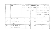
図5に現像ローラ9と現像剤供給ローラ5との周速差の関係を示す。デフォルト紙である普通紙(例えば富士ゼロックス社製J紙)の場合、現像ローラ9と現像剤供給ローラ5とに周速の差はなく、現像ローラ9の膜厚は6.5μmとなる。普通紙より紙の粗いニーナボンド紙のようなラフ紙の場合、現像ローラの周速を約235mm/sに上げると、現像ローラ9は現像剤供給ローラ5より約21mm/s周速が早くなり、この周速差により現像ローラ9の膜厚が約7.15mmに増加する。また、ザンダース、イコノシルクのような普通紙より滑らかなコート紙の場合、現像ローラの周速を約203mm/sに下げると、現像ローラ9は現像剤供給ローラ5より約11mm/s周速が遅くなり、この周速差により現像ローラ9の膜厚が約6.2mmに減少する。   FIG. 5 shows the relationship of the peripheral speed difference between the developing roller 9 and the developer supply roller 5. In the case of plain paper (for example, J paper manufactured by Fuji Xerox Co., Ltd.) which is the default paper, there is no difference in peripheral speed between the developing roller 9 and the developer supply roller 5, and the film thickness of the developing roller 9 is 6.5 μm. In the case of rough paper such as Ninabond paper, which is rougher than plain paper, if the peripheral speed of the developing roller is increased to about 235 mm / s, the peripheral speed of the developing roller 9 is about 21 mm / s faster than the developer supply roller 5. Due to this peripheral speed difference, the film thickness of the developing roller 9 increases to about 7.15 mm. In the case of coated paper that is smoother than plain paper such as Zanders and Ikonosirk, when the peripheral speed of the developing roller is lowered to about 203 mm / s, the developing roller 9 is slower than the developer supply roller 5 by about 11 mm / s. Thus, the film thickness of the developing roller 9 is reduced to about 6.2 mm due to this peripheral speed difference.

これにより、ラフ紙の場合は現像ローラ9の膜厚を厚くし現像剤を増加させ、コート紙の場合は現像ローラ9の膜厚を薄くし現像剤を減少させるので、それぞれの紙種に対して一定の濃度を確保できる。   Thus, in the case of rough paper, the developing roller 9 is made thicker and the developer is increased, and in the case of coated paper, the developing roller 9 is made thin and the developer is reduced. A certain concentration.

なお、印刷動作終了時とは、定着装置が停止した状態、又は定着装置の熱電源がOFFになった状態としてもよい。   The end of the printing operation may be a state in which the fixing device is stopped or a state in which the thermal power of the fixing device is turned off.

また、現像ローラ周速調整制御を実行する際に、ニーナボンド紙等のラフ紙が入力された場合、現像ローラ9上の現像剤はキャリア液量が減りトナー粒子が増加しているので、制御装置43が現像コントラスト電位を増加させ、感光体13の画像部に付着する現像剤量を増加させてもよい。例えば、通常時、現像ローラ9の電位は400V、感光体13の非画像部の帯電電位は800Vに設定されているが、紙種入力手段45がラフ紙であると入力した場合に、感光体13の画像部の帯電電位を変えずに現像ローラ9の電位を450Vに増加させ、それと共に感光体13の非画像部の帯電電位を900Vに増加させる。これにより感光体13の画像部の現像剤量を増加させることができる。   When rough paper such as nina bond paper is input when executing developing roller peripheral speed adjustment control, the amount of carrier liquid in the developer on the developing roller 9 decreases and toner particles increase. The apparatus 43 may increase the development contrast potential and increase the amount of developer attached to the image portion of the photoreceptor 13. For example, normally, the potential of the developing roller 9 is set to 400 V and the charging potential of the non-image portion of the photosensitive member 13 is set to 800 V. However, when the paper type input unit 45 inputs that the paper is rough paper, The potential of the developing roller 9 is increased to 450V without changing the charging potential of the 13 image portions, and at the same time, the charging potential of the non-image portion of the photoreceptor 13 is increased to 900V. As a result, the amount of developer in the image area of the photoreceptor 13 can be increased.

なお、紙種に応じて現像ローラ周速調整制御を実行すると共に、紙種に応じて現像剤濃度調整制御を実行してもよい。例えば、紙種入力手段45により紙種が決定されると、制御装置43が紙種に応じた現像剤濃度、例えばコート紙等の普通紙より滑らかな紙に対しては約20%、デフォルト紙である普通紙(例えば富士ゼロックス社製J紙)で約25%、ニーナボンド紙等のラフ紙や再生紙等の普通紙より粗い紙に対しては約30%となるように制御する。制御方法は現像剤の設定濃度を変更するだけで、その他は通常時と同様に実行する。   The developing roller peripheral speed adjustment control may be executed according to the paper type, and the developer concentration adjustment control may be executed according to the paper type. For example, when the paper type is determined by the paper type input means 45, the control device 43 sets the developer concentration according to the paper type, for example, about 20% for the paper smoother than plain paper such as coated paper, the default paper. Is about 25% for plain paper (for example, J paper manufactured by Fuji Xerox Co., Ltd.), and about 30% for rough paper such as Ninabond paper and plain paper such as recycled paper. The control method is executed in the same manner as usual, except that the set density of the developer is changed.

図6は本発明の現像装置をプリンタに適用した図である。図6において、80は給紙カセット、81はピックアップローラ、82は分離パッド、83は搬送ローラ対、84はレジストローラ対、85は排紙ローラ対、86、87,88は再給紙ローラ対、90は定着装置、91はヒートローラ、92は加圧ローラ、Pは記録媒体、Lはレーザ走査光学系を示す。   FIG. 6 is a diagram in which the developing device of the present invention is applied to a printer. In FIG. 6, 80 is a paper feed cassette, 81 is a pickup roller, 82 is a separation pad, 83 is a transport roller pair, 84 is a registration roller pair, 85 is a paper discharge roller pair, and 86, 87, 88 are refeed roller pairs. , 90 is a fixing device, 91 is a heat roller, 92 is a pressure roller, P is a recording medium, and L is a laser scanning optical system.

給紙カセット80内に積層された紙等の記録媒体Pがピックアップローラ81と分離パッド82で一枚分離され、搬送ローラ対83、記録媒体Pの斜行と給送タイミングを補正するレジストローラ対84を経て2次転写ユニット70に給送される。2次転写ユニット70では記録媒体Pはフルカラー画像を2次転写される。2次転写された記録媒体Pは、内部に加熱手段を備えたヒートローラ91と外部にゴム等の弾性部材を備えた加圧ローラ92で構成された定着装置90を通過し、フルカラー画像中の熱可塑性樹脂が溶融しながら記録媒体Pへ加圧定着され、所望の画像を得る。   A recording medium P such as paper stacked in the paper feed cassette 80 is separated by a pickup roller 81 and a separation pad 82, and a pair of conveying rollers 83, a pair of registration rollers for correcting skew feeding and feeding timing of the recording medium P. Then, the toner is fed to the secondary transfer unit 70 through 84. In the secondary transfer unit 70, the recording medium P secondarily transfers a full color image. The recording medium P that has been secondarily transferred passes through a fixing device 90 constituted by a heat roller 91 having a heating means inside and a pressure roller 92 having an elastic member such as rubber outside, and the recording medium P in a full-color image While the thermoplastic resin is melted, it is pressure-fixed to the recording medium P to obtain a desired image.

本発明の画像形成部を示す図The figure which shows the image formation part of this invention 本発明の現像ユニットを示す図The figure which shows the image development unit of this invention 本発明の現像剤濃度調整制御部を示す図The figure which shows the developer density adjustment control part of this invention 本発明の紙種に応じた周速制御を示す図The figure which shows the peripheral speed control according to the paper kind of this invention 本発明の1実施形態を示す図The figure which shows one Embodiment of this invention 本発明の現像システムをプリンタに適用した図The figure which applied the developing system of this invention to the printer

符号の説明Explanation of symbols

1…画像形成部、2…現像装置、3…現像剤供給部、4…ならしローラ、5…現像剤供給ローラ、6…現像剤規制ブレード、7…現像剤容器、8…現像部、9…現像ローラ、10…現像ローラクリーナ、11…現像ローラクリーナ回収液貯留部、12…感光部、13…感光体、14…感光体クリーナ、15…感光体クリーナ回収液貯留部、16…帯電部、17…露光部、18…スクイーズ部、19…スクイーズローラ、20…スクイーズローラクリーナ、21…スクイーズローラクリーナ回収液貯留部、22…現像剤濃度調整部、23…トナータンク、24…トナー補給経路、25…第1ポンプ、26…キャリア液タンク、27…キャリア液補給経路、28…第1バルブ、29…第1回収キャリア液搬送経路、30…第2回収キャリア液搬送経路、31…現像剤濃度調整槽、32…撹拌部材、33…第2ポンプ、40…現像剤濃度調整制御部、41…モータ、42…トルクセンサ、43…制御装置、44…現像剤濃度データベース、45…紙種入力手段、60…中間転写ユニット、61…中間転写ベルト、62…駆動ローラ、63…従動ローラ、64…1次転写ローラ、65…中間転写ベルトスクイーズローラ、66…中間転写ベルトスクイーズローラクリーナ、67…中間転写ベルトスクイーズローラクリーナ回収液貯留部、68…中間転写ベルトクリーナ、69…中間転写ベルトクリーナ回収液貯留部、70…2次転写ユニット、71…2次転写ローラ、80…給紙カセット、81…ピックアップローラ、82…分離パッド、83…搬送ローラ対、84…レジストローラ対、85…排紙ローラ対、86、87,88…再給紙ローラ対、90…定着装置、91…ヒートローラ、92…加圧ローラ、P…記録媒体、L…レーザ走査光学系

DESCRIPTION OF SYMBOLS 1 ... Image formation part, 2 ... Developing apparatus, 3 ... Developer supply part, 4 ... Leveling roller, 5 ... Developer supply roller, 6 ... Developer control blade, 7 ... Developer container, 8 ... Development part, 9 DESCRIPTION OF SYMBOLS Developing roller, 10 Developing roller cleaner, 11 Developing roller cleaner collected liquid storage unit, 12 Photosensitive unit, 13 Photoconductor, 14 Photoconductor cleaner, 15 Photoconductor cleaner collected liquid storage unit, 16 Charging unit , 17... Exposure unit, 18. , 25 ... first pump, 26 ... carrier liquid tank, 27 ... carrier liquid supply path, 28 ... first valve, 29 ... first recovered carrier liquid transport path, 30 ... second recovered carrier liquid transport Path 31, developer concentration adjusting tank 32, stirring member 33, second pump 40, developer concentration adjusting control unit 41, motor 42, torque sensor 43, control device 44, developer concentration database 45 ... paper type input means, 60 ... intermediate transfer unit, 61 ... intermediate transfer belt, 62 ... drive roller, 63 ... driven roller, 64 ... primary transfer roller, 65 ... intermediate transfer belt squeeze roller, 66 ... intermediate transfer belt Squeeze roller cleaner, 67 ... intermediate transfer belt squeeze roller cleaner recovered liquid storage section, 68 ... intermediate transfer belt cleaner, 69 ... intermediate transfer belt cleaner recovered liquid storage section, 70 ... secondary transfer unit, 71 ... secondary transfer roller, 80 ... Paper feeding cassette, 81 ... Pickup roller, 82 ... Separation pad, 83 ... Conveying roller pair, 84 ... Registration roller pair, 8 ... discharge rollers, 86, 87, 88 ... re-feed rollers, 90 ... fixing device, 91 ... heating roller, 92 ... pressing roller, P ... recording medium, L ... laser scanning system

Claims (6)

現像剤を担持する現像ローラと、現像剤を前記現像ローラに供給する現像剤供給ローラと、前記現像ローラに担持した現像剤により顕像を形成する感光体と、前記感光体の顕像を転写する転写手段とを有する画像形成部と、高濃度トナーを貯留したトナータンクと、キャリア液を貯留したキャリア液タンクと、前記トナータンクから高濃度トナーを補給し、前記キャリア液タンクからキャリア液を補給することで現像剤の濃度を調整する現像剤濃度調整槽とを有する現像剤濃度調整部とを備え、前記現像剤濃度調整部で濃度を調整された現像剤により前記画像形成部で画像形成される現像システムにおいて、紙種を入力する紙種入力手段と、前記紙種入力手段が入力した紙種に応じて前記現像剤供給ローラと前記現像ローラとの周速差を調整するように制御する制御装置とを有する現像剤濃度調整制御部を備えたことを特徴とする現像システム。 A developing roller carrying a developer; a developer supplying roller for supplying the developer to the developing roller; a photoconductor for forming a developed image with the developer carried on the developing roller; and a transferred image of the photoreceptor. An image forming unit having a transfer means, a toner tank storing high-concentration toner, a carrier liquid tank storing carrier liquid, replenishing high-concentration toner from the toner tank, and supplying carrier liquid from the carrier liquid tank A developer concentration adjusting unit having a developer concentration adjusting tank for adjusting the concentration of the developer by replenishing, and forming an image in the image forming unit by the developer whose concentration is adjusted by the developer concentration adjusting unit. In the developing system, the paper type input means for inputting the paper type, and the peripheral speed difference between the developer supply roller and the developing roller is adjusted according to the paper type input by the paper type input means. Development system characterized by comprising a developer density adjustment control unit and a control unit for controlling the so that. 前記制御装置は、前記紙種入力手段がデフォルト紙より粗い紙と入力した場合、前記現像剤供給ローラの周速を前記現像ローラの周速よりも上げるように制御することを特徴とする請求項1に記載の現像システム。 The control device controls the peripheral speed of the developer supply roller to be higher than the peripheral speed of the developing roller when the paper type input unit inputs paper coarser than default paper. 2. The development system according to 1. 前記制御装置は、前記紙種入力手段がデフォルト紙より粗い紙と入力した場合、前記感光体と前記現像ローラとのコントラスト電位を上げるように制御することを特徴とする請求項1又は2に記載の現像システム。 3. The control device according to claim 1, wherein when the paper type input unit inputs paper coarser than default paper, the control device performs control so as to increase a contrast potential between the photoconductor and the developing roller. Development system. 前記制御装置は、前記紙種入力手段がデフォルト紙より滑らかな紙と入力した場合、前記現像剤供給ローラの周速を前記現像ローラの周速よりも下げるように制御することを特徴とする請求項1に記載の現像システム。 The control device controls the peripheral speed of the developer supply roller to be lower than the peripheral speed of the developing roller when the paper type input unit inputs paper smoother than the default paper. Item 2. The developing system according to Item 1. 前記現像剤濃度調整部は、モータと、前記モータにより作動され前記現像剤濃度調整槽内の現像剤を撹拌する撹拌部材とを有し、前記現像剤濃度調整制御部は、前記モータのトルクを検出するトルクセンサと、前記モータのトルクに対応する現像剤濃度のデータを格納する現像剤濃度データベースとを有し、前記制御装置は、前記トルクセンサの検出値と前記現像剤濃度データベースのデータとから現像剤濃度を算出することを特徴とする請求項1乃至4のいずれかに記載の現像システム。 The developer concentration adjusting unit includes a motor and a stirring member that is operated by the motor and stirs the developer in the developer concentration adjusting tank, and the developer concentration adjustment control unit adjusts the torque of the motor. A torque sensor to detect, and a developer concentration database storing developer concentration data corresponding to the torque of the motor, and the control device includes a detection value of the torque sensor and data of the developer concentration database; The developing system according to claim 1, wherein the developer concentration is calculated from the developer. 前記画像形成部は、前記感光体のキャリア液を除去する感光体キャリア液除去手段を有することを特徴とする請求項1乃至5のいずれかに記載の現像システム。

The developing system according to claim 1, wherein the image forming unit includes a photosensitive carrier liquid removing unit that removes the carrier liquid of the photosensitive member.

JP2005242370A 2005-08-24 2005-08-24 Developing system Pending JP2007057772A (en)

Priority Applications (2)

Application Number Priority Date Filing Date Title
JP2005242370A JP2007057772A (en) 2005-08-24 2005-08-24 Developing system
US11/466,711 US7561815B2 (en) 2005-08-24 2006-08-23 Image forming apparatus that controls development conditions based on paper type

Applications Claiming Priority (1)

Application Number Priority Date Filing Date Title
JP2005242370A JP2007057772A (en) 2005-08-24 2005-08-24 Developing system

Publications (2)

Publication Number Publication Date
JP2007057772A true JP2007057772A (en) 2007-03-08
JP2007057772A5 JP2007057772A5 (en) 2008-10-09

Family

ID=37921346

Family Applications (1)

Application Number Title Priority Date Filing Date
JP2005242370A Pending JP2007057772A (en) 2005-08-24 2005-08-24 Developing system

Country Status (1)

Country Link
JP (1) JP2007057772A (en)

Cited By (5)

* Cited by examiner, † Cited by third party
Publication number Priority date Publication date Assignee Title
JP2007219068A (en) * 2006-02-15 2007-08-30 Konica Minolta Holdings Inc Liquid development device and image forming apparatus provided therewith
JP2008209716A (en) * 2007-02-27 2008-09-11 Konica Minolta Business Technologies Inc Apparatus and method for measuring concentration of developer, apparatus and method for adjusting concentration of developer, and apparatus for forming image
JP2009002998A (en) * 2007-06-19 2009-01-08 Konica Minolta Business Technologies Inc Developer concentration adjusting device, developer concentration adjusting method, and image forming apparatus
JP2009003346A (en) * 2007-06-25 2009-01-08 Konica Minolta Business Technologies Inc Developer concentration adjusting device, developer concentration adjustment method, and image forming apparatus
JP2009069586A (en) * 2007-09-14 2009-04-02 Konica Minolta Business Technologies Inc Developer concentration regulator, developer concentration regulation method, and image forming device

Citations (8)

* Cited by examiner, † Cited by third party
Publication number Priority date Publication date Assignee Title
JPH04253072A (en) * 1991-01-30 1992-09-08 Ricoh Co Ltd Wet type image forming device
JPH09329972A (en) * 1996-06-12 1997-12-22 Ricoh Co Ltd Wet-type image forming device
JP2002148947A (en) * 2000-11-07 2002-05-22 Ricoh Co Ltd Regulation blade, wet type developing device and wet type image forming device
JP2002304061A (en) * 2001-04-09 2002-10-18 Toshiba Mach Co Ltd Enriched toner supply device and method for wet electrophotographic printing machine
JP2003167442A (en) * 2001-12-04 2003-06-13 Pfu Ltd Method for controlling toner recycling of electrophotographic device using liquid developer with high viscosity
JP2003241520A (en) * 2002-02-15 2003-08-29 Mitsubishi Heavy Ind Ltd Wet electrophotographic printing device
JP2004029615A (en) * 2002-06-28 2004-01-29 Ricoh Co Ltd Liquid type image forming device
JP2005189410A (en) * 2003-12-25 2005-07-14 Ricoh Co Ltd Image forming apparatus

Patent Citations (8)

* Cited by examiner, † Cited by third party
Publication number Priority date Publication date Assignee Title
JPH04253072A (en) * 1991-01-30 1992-09-08 Ricoh Co Ltd Wet type image forming device
JPH09329972A (en) * 1996-06-12 1997-12-22 Ricoh Co Ltd Wet-type image forming device
JP2002148947A (en) * 2000-11-07 2002-05-22 Ricoh Co Ltd Regulation blade, wet type developing device and wet type image forming device
JP2002304061A (en) * 2001-04-09 2002-10-18 Toshiba Mach Co Ltd Enriched toner supply device and method for wet electrophotographic printing machine
JP2003167442A (en) * 2001-12-04 2003-06-13 Pfu Ltd Method for controlling toner recycling of electrophotographic device using liquid developer with high viscosity
JP2003241520A (en) * 2002-02-15 2003-08-29 Mitsubishi Heavy Ind Ltd Wet electrophotographic printing device
JP2004029615A (en) * 2002-06-28 2004-01-29 Ricoh Co Ltd Liquid type image forming device
JP2005189410A (en) * 2003-12-25 2005-07-14 Ricoh Co Ltd Image forming apparatus

Cited By (6)

* Cited by examiner, † Cited by third party
Publication number Priority date Publication date Assignee Title
JP2007219068A (en) * 2006-02-15 2007-08-30 Konica Minolta Holdings Inc Liquid development device and image forming apparatus provided therewith
JP2008209716A (en) * 2007-02-27 2008-09-11 Konica Minolta Business Technologies Inc Apparatus and method for measuring concentration of developer, apparatus and method for adjusting concentration of developer, and apparatus for forming image
US8121504B2 (en) 2007-02-27 2012-02-21 Konica Minolta Business Technologies, Inc. Apparatus and method for measuring or controlling concentration of liquid developer
JP2009002998A (en) * 2007-06-19 2009-01-08 Konica Minolta Business Technologies Inc Developer concentration adjusting device, developer concentration adjusting method, and image forming apparatus
JP2009003346A (en) * 2007-06-25 2009-01-08 Konica Minolta Business Technologies Inc Developer concentration adjusting device, developer concentration adjustment method, and image forming apparatus
JP2009069586A (en) * 2007-09-14 2009-04-02 Konica Minolta Business Technologies Inc Developer concentration regulator, developer concentration regulation method, and image forming device

Similar Documents

Publication Publication Date Title
US7561815B2 (en) Image forming apparatus that controls development conditions based on paper type
US7149459B2 (en) Application roller and image forming apparatus
US8023847B2 (en) Image forming apparatus and image forming method
JP2007057772A (en) Developing system
JP4816881B2 (en) Image forming apparatus and image forming method
JP2006337605A (en) Image forming apparatus
JP2006220800A (en) Image forming apparatus
JP5094211B2 (en) Image forming apparatus
JP4363035B2 (en) Image forming apparatus
JP4385732B2 (en) Image forming apparatus and method
JP5541071B2 (en) Image forming apparatus
JP4798339B2 (en) Liquid toner concentration adjusting apparatus and image forming apparatus
JP4780286B2 (en) Development system
JP4766229B2 (en) Image forming apparatus
JP2007057768A (en) Developing system
JP2007057771A (en) Developing system
JP5234244B2 (en) Liquid developer recovery system and image forming apparatus
JP2007057770A (en) Developing system
JP4636293B2 (en) Developing device and image forming apparatus
JP2007114382A (en) Image forming apparatus and image forming method
JP4573044B2 (en) Developing device and image forming apparatus
JP6814387B2 (en) Cleaning equipment, process cartridges, and image forming equipment
JP2007025184A (en) Image forming apparatus and image forming method
JP2007114380A (en) Developing system for liquid development and developing method for liquid development
JP2014095862A (en) Non-magnetic one-component developing device and non-magnetic one-component developing method, process unit, and image forming apparatus

Legal Events

Date Code Title Description
A521 Written amendment

Free format text: JAPANESE INTERMEDIATE CODE: A523

Effective date: 20080821

A621 Written request for application examination

Free format text: JAPANESE INTERMEDIATE CODE: A621

Effective date: 20080821

A977 Report on retrieval

Effective date: 20101126

Free format text: JAPANESE INTERMEDIATE CODE: A971007

A131 Notification of reasons for refusal

Free format text: JAPANESE INTERMEDIATE CODE: A131

Effective date: 20101201

A521 Written amendment

Effective date: 20110127

Free format text: JAPANESE INTERMEDIATE CODE: A523

A131 Notification of reasons for refusal

Effective date: 20110302

Free format text: JAPANESE INTERMEDIATE CODE: A131

A521 Written amendment

Free format text: JAPANESE INTERMEDIATE CODE: A523

Effective date: 20110426

A131 Notification of reasons for refusal

Free format text: JAPANESE INTERMEDIATE CODE: A131

Effective date: 20110720

A02 Decision of refusal

Effective date: 20111214

Free format text: JAPANESE INTERMEDIATE CODE: A02