JP2007028383A - Imaging apparatus and control method thereof - Google Patents
Imaging apparatus and control method thereof Download PDFInfo
- Publication number
- JP2007028383A JP2007028383A JP2005209956A JP2005209956A JP2007028383A JP 2007028383 A JP2007028383 A JP 2007028383A JP 2005209956 A JP2005209956 A JP 2005209956A JP 2005209956 A JP2005209956 A JP 2005209956A JP 2007028383 A JP2007028383 A JP 2007028383A
- Authority
- JP
- Japan
- Prior art keywords
- motor
- imaging apparatus
- image
- processing state
- zoom
- Prior art date
- Legal status (The legal status is an assumption and is not a legal conclusion. Google has not performed a legal analysis and makes no representation as to the accuracy of the status listed.)
- Withdrawn
Links
Images


Classifications
-
- H—ELECTRICITY
- H04—ELECTRIC COMMUNICATION TECHNIQUE
- H04N—PICTORIAL COMMUNICATION, e.g. TELEVISION
- H04N23/00—Cameras or camera modules comprising electronic image sensors; Control thereof
- H04N23/60—Control of cameras or camera modules
- H04N23/66—Remote control of cameras or camera parts, e.g. by remote control devices
-
- H—ELECTRICITY
- H04—ELECTRIC COMMUNICATION TECHNIQUE
- H04N—PICTORIAL COMMUNICATION, e.g. TELEVISION
- H04N23/00—Cameras or camera modules comprising electronic image sensors; Control thereof
- H04N23/60—Control of cameras or camera modules
- H04N23/69—Control of means for changing angle of the field of view, e.g. optical zoom objectives or electronic zooming
Abstract
Description
本発明は、ビデオカメラや監視カメラ等の撮像装置及びその撮像装置を制御する制御方法に関する。 The present invention relates to an imaging apparatus such as a video camera or a surveillance camera, and a control method for controlling the imaging apparatus.
従来、ビデオカメラや監視カメラ等の撮像装置において、そのカメラ部を、モータにより駆動するパン(PAN)機構やチルト(TILT)機構により制御することにより、撮影方向を自在に変えられるものが普及してきている。 2. Description of the Related Art Conventionally, in an imaging apparatus such as a video camera or a surveillance camera, an apparatus that can freely change a shooting direction by controlling a camera unit by a pan (PAN) mechanism or a tilt (TILT) mechanism driven by a motor has become widespread. ing.
例えば、監視カメラにより被写体(以下、オブジェクトと記述する。)を撮影する際に、目標とするオブジェクトが人や動物である場合には、一般的には、監視カメラの操作者がモニタの画面を見ながら、カメラレンズの向き方向を移動するように操作してオブジェクトを追跡するが、カメラレンズの向き方向の移動が遅すぎたり、早すぎたりした場合には、オブジェクトを見失ってしまうことがあるので、オブジェクトを自動的に追尾する自動追尾機能の出現が望まれている。 For example, when shooting a subject (hereinafter referred to as an object) with a monitoring camera, if the target object is a person or an animal, the operator of the monitoring camera generally displays the monitor screen. While watching, the object is tracked by moving in the direction of the camera lens, but if the camera lens is moved too late or too early, the object may be lost. Therefore, the appearance of an automatic tracking function that automatically tracks an object is desired.
また、例えば、ビデオカメラでオブジェクトを撮影する際に、目標とするオブジェクトの動きが大きく変化する場合や、急峻に変化する場合は、オブジェクトを手動で追尾することが困難であるので、オブジェクトを自動的に追尾する自動追尾機能の出現が望まれている(例えば、特許文献1参照)。 For example, when shooting an object with a video camera, if the movement of the target object changes significantly or changes sharply, it is difficult to manually track the object. The appearance of an automatic tracking function that automatically tracks is desired (see, for example, Patent Document 1).
また、例えば、ビデオカメラを操作している場合に、ズーム倍率を手動で変更するのことは、時として面倒な場合がある。例えば、運動会のリレー競争等の場面をビデオカメラで撮影している際に、ビデオカメラの録画ボタンを押しながらズーム倍率を手動で変更すると、撮影している映像内のオブジェクトが大きくなりすぎたり、小さくなりすぎたりしてしまう。 In addition, for example, when operating a video camera, it is sometimes troublesome to manually change the zoom magnification. For example, when shooting a scene such as an athletic meet relay competition with a video camera, if you manually change the zoom magnification while pressing the record button of the video camera, the object in the video you are shooting becomes too large, It becomes too small.
このため、追尾しているオブジェクトを中心にして、自動的にズーム倍率を調節する自動ズーム機能が望まれるが、現状においては、そのような機能は提案されていない。 For this reason, an automatic zoom function that automatically adjusts the zoom magnification around the tracked object is desired, but at present, such a function has not been proposed.
近年、カメラのレンズ等を駆動するための駆動源として、超音波モータが採用されてきている。 In recent years, an ultrasonic motor has been adopted as a drive source for driving a camera lens and the like.
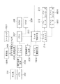
図22は、一般的な超音波モータの概略構成を示す模式図である。 FIG. 22 is a schematic diagram showing a schematic configuration of a general ultrasonic motor.
図22において、2201は振動体であって、圧電素子を積層している。そして、特定の周波数の信号としてA相信号2208と、B相信号2209を振動体2201に供給することにより、共振して矢印2205方向または矢印2206方向にメカニカル的な進行波を発生する。
In FIG. 22,
この振動体2201に取り付けられているステータ2202により振動体2201の振動をメカニカル的に増幅する。そして、ステータ2202にリブ2207を介して圧接されているロータ2203が、図中矢印2205方向または矢印2206方向に回転する。このロータ2203の回転をシャフト2204に伝えて、回転運動を発生する。
The vibration of the vibrating
このような構成の超音波モータの特徴としては、駆動時の加減速時間が短いことである。 A characteristic of the ultrasonic motor having such a configuration is that the acceleration / deceleration time during driving is short.
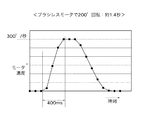
図23は、一般的なブラシレスモータの回転速度を示すグラフであり、同図において、横軸は時間を、縦軸はモータの回転速度をそれぞれ示している。 FIG. 23 is a graph showing the rotation speed of a general brushless motor, in which the horizontal axis indicates time and the vertical axis indicates the rotation speed of the motor.
ブラシレスモータの場合、図23に示すように、回転速度300°/秒に達するまでに400msの時間が必要である。 In the case of a brushless motor, as shown in FIG. 23, it takes 400 ms to reach a rotational speed of 300 ° / second.
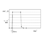
図24は、一般的な超音波モータ(USM)の回転速度を示すグラフであり、同図において、横軸は時間を、縦軸はモータの回転速度をそれぞれ示している。 FIG. 24 is a graph showing the rotation speed of a general ultrasonic motor (USM), in which the horizontal axis indicates time and the vertical axis indicates the rotation speed of the motor.
超音波モータの場合、図24に示すように、回転速度300°/秒に達するまでの時間は僅か20msであり、ブラシレスモータに比して短い加減速時間により駆動することが可能である。
上述したような自動追尾機能は、既に商品化されている監視カメラ等に採用されているが、カメラのレンズの向き方向を変えるためのパン機構及びチルト機構の駆動用モータは、ブラシレスDCモータやステッピングモータであり、このようなモータは、低速でしか加減速できないため、オブジェクトの急峻な動きに対応できないのが現状である。 The automatic tracking function as described above is employed in surveillance cameras and the like that have already been commercialized. However, the drive motor for the pan mechanism and the tilt mechanism for changing the direction of the lens of the camera is a brushless DC motor, Since it is a stepping motor, since such a motor can only accelerate and decelerate at low speed, it cannot currently cope with a steep movement of an object.
また、従来におけるモータでは、急峻な停止ができないため、特許文献1に開示されているように、回転動作を行いながら撮影動作も行うこととなり、撮影画像の流れ等が発生して、画質が低下してしまうという不具合があった。
In addition, since a conventional motor cannot be stopped suddenly, as disclosed in
また、超音波モータによりズームレンズを制御する自動ズーム機能を有するカメラは商品化されているが、上述したような自動追尾機能と連動した自動ズーム機能を有するビデオカメラは存在せず、そのために、ビデオカメラでの撮影時に手動操作によりズーム機能を制御しなければならないという操作上の煩雑さがあった。 In addition, a camera having an automatic zoom function for controlling a zoom lens by an ultrasonic motor has been commercialized, but there is no video camera having an automatic zoom function in conjunction with the automatic tracking function as described above. When shooting with a video camera, the zoom function has to be controlled by manual operation.
また、パン機構やチルト機構やズーム機構を駆動するために、そのまま超音波モータを使用すると、撮影時にも高速で超音波モータが動作しているため、撮影画像が流れて画質が悪くなり、追尾時のオブジェクトを特定する画像処理時に、そのオブジェクトを特定することができなくなるという不具合があった。 In addition, if an ultrasonic motor is used as it is to drive the pan mechanism, tilt mechanism, and zoom mechanism, the ultrasonic motor operates at high speed even during shooting, so the shot image flows and image quality deteriorates, and tracking is performed. At the time of image processing for specifying an object at the time, there was a problem that the object could not be specified.
本発明は、上述したような従来技術の有する問題点に鑑みてなされたもので、その目的は、オブジェクトの追跡が容易な追尾機能を実現可能な撮像装置及びその制御方法を提供することである。 The present invention has been made in view of the above-described problems of the prior art, and an object thereof is to provide an imaging apparatus capable of realizing a tracking function that can easily track an object and a control method thereof. .
上記目的を達成するために本発明の撮像装置は、カメラ部を水平方向に回転するパン機構と、前記カメラ部を上下方向に動作するチルト機構と、前記カメラ部のレンズユニットを制御するズーム機構のいずれかの機構を有する撮像装置において、前記いずれかの機構に使用するモータを停止処理状態と低速駆動処理状態と高速駆動処理状態のいずれかに択一的に制御するモータ制御手段と、前記モータが停止処理状態または低速駆動処理状態にある時間に並行して画像撮影手段により画像を撮影処理するように制御する撮影制御手段とを有することを特徴とする。 In order to achieve the above object, an imaging apparatus according to the present invention includes a pan mechanism that rotates a camera unit in a horizontal direction, a tilt mechanism that operates the camera unit in a vertical direction, and a zoom mechanism that controls a lens unit of the camera unit. In the imaging apparatus having any one of the mechanisms, motor control means for controlling the motor used for any one of the mechanisms alternatively to any one of the stop processing state, the low speed driving processing state, and the high speed driving processing state, and And a photographing control means for controlling the image photographing means to photograph an image in parallel with the time when the motor is in the stop processing state or the low speed driving processing state.
また、上記目的を達成するために本発明の撮像装置は、撮影処理時間と画像解析時間とモータ駆動時間とを1サイクルとして繰り返し処理する画像撮影手段と画像解析手段とモータ制御手段とを有する撮像装置において、前記画像解析手段により第1のモータ駆動目標値を求め且つ前記モータ駆動時間にモータの駆動を開始する第1のモードと、モータ駆動履歴に基づき第2のモータ駆動目標値を求め且つ前記画像解析時間に並行して前記モータの駆動を開始する第2のモードとを有し、前記第2のモードで前記モータの駆動を開始する際に前記第2のモータ駆動目標値を前記画像解析手段により求められた前記第1のモータ駆動目標値に変更する目標値変更手段を有することを特徴とする。 In order to achieve the above object, an image pickup apparatus of the present invention includes an image pickup means, an image analysis means, and a motor control means that repeatedly process a shooting processing time, an image analysis time, and a motor driving time as one cycle. In the apparatus, a first motor drive target value is obtained by the image analysis means and a motor is driven during the motor drive time, and a second motor drive target value is obtained based on the motor drive history. A second mode in which driving of the motor is started in parallel with the image analysis time, and the second motor driving target value is set to the image when starting driving of the motor in the second mode. It has a target value changing means for changing to the first motor drive target value obtained by the analyzing means.
また、上記目的を達成するために本発明の撮像装置の制御方法は、カメラ部を水平方向に回転するパン機構と、前記カメラ部を上下方向に動作するチルト機構と、前記カメラ部のレンズユニットを制御するズーム機構のいずれかの機構を有する撮像装置を制御する制御方法において、前記いずれかの機構に使用するモータが停止処理状態と低速駆動処理状態と高速駆動処理状態のいずれかに択一的に制御するモータ制御ステップと、前記モータが停止処理状態または低速駆動処理状態にある時間に並行して撮影手段により画像を撮影処理するように制御する撮影制御ステップとを有することを特徴とする。 In order to achieve the above object, a method for controlling an imaging apparatus according to the present invention includes a pan mechanism that rotates a camera unit in a horizontal direction, a tilt mechanism that operates the camera unit in a vertical direction, and a lens unit of the camera unit. In the control method for controlling an image pickup apparatus having any one of the zoom mechanisms for controlling the motor, the motor used for any one of the mechanisms is selected from the stop processing state, the low-speed driving processing state, and the high-speed driving processing state. A motor control step for controlling the motor and a photographing control step for controlling the photographing means to photograph an image in parallel with the time during which the motor is in the stop processing state or the low-speed driving processing state. .
また、上記目的を達成するために本発明の撮像装置の制御方法は、撮影処理時間と画像解析時間とモータ駆動時間とを1サイクルとして繰り返し処理する画像撮影ステップと、画像を解析する解析ステップと、モータを制御するモータ制御ステップとを有する撮像装置を制御する制御方法において、前記画像解析ステップにより第1のモータ駆動目標値を求め且つ前記モータ駆動時間にモータの駆動を開始する第1のモードと、モータ駆動履歴に基づき第2のモータ駆動目標値を求め且つ前記画像解析時間に並行して前記モータの駆動を開始する第2のモードとを有し、前記第2のモードで前記モータの駆動を開始する際に前記第2のモータ駆動目標値を前記画像解析ステップにより求められた前記第1のモータ駆動目標値に変更する目標値変更ステップを有することを特徴とする。 In order to achieve the above object, a method for controlling an imaging apparatus according to the present invention includes an image capturing step for repeatedly processing an imaging processing time, an image analysis time, and a motor driving time as one cycle, and an analysis step for analyzing an image. And a motor control step for controlling a motor, wherein a first motor drive target value is obtained by the image analysis step and motor drive is started during the motor drive time. And a second mode for determining a second motor drive target value based on the motor drive history and starting driving the motor in parallel with the image analysis time, and in the second mode, A target value for changing the second motor drive target value to the first motor drive target value obtained by the image analysis step when driving is started. Characterized in that it has a further step.
本発明によれば、モータを用いてパン機構とチルト機構とズーム機構のいずれかの機構を制御する際に、モータが停止している時間や、低速駆動状態にある時間に画像を撮影処理することで、撮影処理時の画像の画質を良好にし、画像解析時におけるオブジェクトの認識率を高めることができる。 According to the present invention, when a motor is used to control any one of the pan mechanism, the tilt mechanism, and the zoom mechanism, an image is captured during the time when the motor is stopped or during the low-speed driving state. Thus, it is possible to improve the image quality of the image at the time of shooting processing and increase the recognition rate of the object at the time of image analysis.
また、画像解析時間に並行してモータの駆動を開始する第2のモータ駆動モードを設けることにより、オブジェクトの急峻な移動に対応できる。 In addition, by providing a second motor drive mode that starts driving the motor in parallel with the image analysis time, it is possible to cope with a steep movement of the object.
また、オブジェクトを追尾する追尾機能と共に、ズーム機構を自動的に制御する自動ズーム機能を設けることにより、画像撮影時の手動によるズーム操作を省くことができ、煩雑な操作を無くすことができる。 Further, by providing an automatic zoom function for automatically controlling the zoom mechanism together with a tracking function for tracking an object, a manual zoom operation at the time of image shooting can be omitted, and a complicated operation can be eliminated.
以下、本発明の実施の形態を、図1〜図21に基づき説明する。 Hereinafter, embodiments of the present invention will be described with reference to FIGS.
(第1の実施の形態)
まず、本発明の第1の実施の形態を、図1〜図5に基づき説明する。
(First embodiment)
First, a first embodiment of the present invention will be described with reference to FIGS.
図1は、本発明の第1の実施の形態に係る撮像装置である監視カメラにおけるオブジェクト追尾処理時のモータ制御の概念を示すグラフであり、同図において、縦軸はモータの回転速度を、横軸は時間をそれぞれ示す。 FIG. 1 is a graph showing the concept of motor control during object tracking processing in the surveillance camera that is the imaging apparatus according to the first embodiment of the present invention. In the figure, the vertical axis represents the rotation speed of the motor. The horizontal axis indicates time.
また、図1において、横軸方向は、撮影時間T1、画像解析時間T2、モータ駆動占有時間T3に割り振られており、本実施の形態においては、それぞれ、52ms、55ms、60msとしている。T1とT2とT3の合計時間は167msであり、ビデオ信号として用いられるNTSC信号のフレーム周波数と一致させ、撮影時間T1で撮影した映像をビデオ信号で出力可能としている。 In FIG. 1, the horizontal axis direction is assigned to the photographing time T1, the image analysis time T2, and the motor drive occupation time T3. In this embodiment, they are 52 ms, 55 ms, and 60 ms, respectively. The total time of T1, T2, and T3 is 167 ms, which matches the frame frequency of the NTSC signal used as the video signal, and the video imaged at the imaging time T1 can be output as a video signal.
T1,T2,T3を1サイクルとして、そのサイクルを繰り返して撮影しながら、画像解析時間T2,T5にオブジェクトの追尾処理等を行っている。 T1, T2, and T3 are defined as one cycle, and object tracking processing and the like are performed at image analysis times T2 and T5 while photographing by repeating the cycle.
図1において、105で追尾処理を開始すると、まず、時間T1で撮影処理を行い、時間T2で画像解析を行う。この画像解析処理中における106でオブジェクトを発見し、そのオブジェクトが画像のどの位置に存在するかを解析して、回転角度を求める。例えば、監視カメラの右方向6°の位置に通常とは異なるオブジェクトが見つかった場合は、このオブジェクトが追尾対象のオブジェクトであると判断し、モータが6°右方向に回転する。 In FIG. 1, when tracking processing is started at 105, first, imaging processing is performed at time T1, and image analysis is performed at time T2. An object is found at 106 during the image analysis processing, and the position of the object in the image is analyzed to obtain the rotation angle. For example, when an object different from normal is found at a position 6 ° to the right of the surveillance camera, it is determined that this object is a tracking target object, and the motor rotates 6 ° to the right.
そして、107でモータの回転角度が確定し、そのモータの回転が開始すると、モータ駆動占有時間T3の間モータが回転し、その後、108でモータの回転を終了するように制御する。 Then, when the rotation angle of the motor is determined at 107 and the rotation of the motor is started, the motor is rotated during the motor drive occupation time T3, and thereafter, the control is performed so as to end the rotation of the motor at 108.
図1において、波形101はモータ回転速度の一例を示し、具体的には、追尾対象のオブジェクトが低速で回転する例であり、例えば、モータが1°以下の低速回転で動作している例を示している。また、波形102はモータ回転速度の一例を示しており、具体的には、追尾対象のオブジェクトが高速で動いており、その動きに追従するために、モータ駆動占有時間T3全体を使って、例えば、モータが6°回転する場合でのモータ回転速度を示している。更に、波形103はモータ回転速度の一例を示しており、具体的には、追尾対象のオブジェクトが高速で動いており、予測回転する場合のモータの回転速度を示している。
In FIG. 1, a
T1からT3の処理により、1サイクルの処理を終了する。 One cycle of processing is completed by the processing from T1 to T3.
モータ駆動占有時間T3内での最大モータ回転角度を6°とし、画像解析時間T2での画像解析の結果、例えば、オブジェクトが10°移動している場合、モータ駆動占有時間T3全体を使ってもモータが回転しきれない。 If the maximum motor rotation angle within the motor drive occupation time T3 is 6 ° and the result of the image analysis at the image analysis time T2 is, for example, that the object has moved 10 °, the entire motor drive occupation time T3 may be used. The motor cannot rotate.
そこで、次のサイクルでは、撮影時間T4で撮影を行った後、画像解析時間T5に平行して、109でモータの予測回転を開始する。モータが回転し切れなかった角度(10°−6°=4°)と、オブジェクトの移動角度10°とを合計した14°だけモータを回転するように制御する。 Therefore, in the next cycle, after shooting at the shooting time T4, in parallel with the image analysis time T5, the motor starts a predicted rotation at 109. Control is performed so that the motor is rotated by 14 °, which is the sum of the angle at which the motor has not been rotated (10 ° −6 ° = 4 °) and the moving angle of the object is 10 °.
画像解析時間T5での画像解析により110でモータの回転角度が確定し、例えば、モータが16°回転するように解析結果が出ると、モータの回転角度を14°から16°に変更指示して、モータ駆動占有時間T6の間モータの回転を続け、その後、111でモータの回転を終了するように制御する。 According to the image analysis at the image analysis time T5, the rotation angle of the motor is determined at 110. For example, when an analysis result is output so that the motor rotates by 16 °, an instruction to change the rotation angle of the motor from 14 ° to 16 ° is given. Then, the motor continues to rotate during the motor drive occupation time T6, and then the control is performed to end the rotation of the motor at 111.
以上、追尾対象のオブジェクトに応じて、本実施の形態に係る撮像装置におけるモータ回転制御の概略を説明した。 The outline of the motor rotation control in the imaging apparatus according to the present embodiment has been described above according to the tracking target object.
勿論、モータの回転角度については、上述した実施の形態において説明した角度だけではなく、画像解析結果により随時修正され、その結果に応じて、モータは指定角度回転するように制御される。 Of course, the rotation angle of the motor is corrected not only by the angle described in the above-described embodiment but also by the image analysis result, and the motor is controlled to rotate by a specified angle according to the result.
図2は、本実施の形態に係る撮像装置である追尾機能付き監視カメラの構成を示すブロック図である。 FIG. 2 is a block diagram illustrating a configuration of a monitoring camera with a tracking function that is an imaging apparatus according to the present embodiment.
図2において、201は光学系であり、レンズ、自動露出調節(AE)機構、ズーム(ZOOM)機構、自動焦点調節(AFC)機構等を具備している。202は光電変換素子(CCD)で、光学系201を通った光はCCD202に集光する。CCD202は、集光した光を元に、セル毎に電荷を蓄積して画像を得るものである。203は信号処理回路で、CCD202から入手した画像のアナログ信号を元に信号処理を行った後、A/D変換する。204はゲートアレイで、色処理やエッジ強調処理等の画像処理回路を含むものである。205はビデオ信号処理回路で、画像処理された後の信号を、NTSCやPAL等のビデオ信号に変換し、モニタTVで映像が観測できるようにビデオ出力するものである。
In FIG. 2, an
206は画像解析回路で、ゲートアレイ204で画像処理された画像を元に、追尾処理としてオブジェクトを抽出し、オブジェクトが抽出できたか否かを後述するCPU207に送信するものである。また、画像解析回路206は、オブジェクトが存在する場合に、画像の中心から何度の位置にオブジェクトが存在するかを計算し、その計算結果を後述するCPU207へ送信する。
An
207はCPU(中央制御装置)で、ROM(リードオンリーメモリ)208に格納されたプログラムの命令に従い処理を実行し、RAM(ランダムアクセスメモリ)209にデータや、フラグを格納するものである。また、CPU207は、図1で示した、撮影処理、画像解析処理、モータ制御等の指令を各ブロックに指令し、内蔵するタイマを使って時間管理すると共に、受け取った信号に基づいて各種の処理を実行する。また、CPU207は、画像解析回路206からの信号により、オブジェクトが存在すること及びオブジェクトの移動角度に基づき後述するパン(回転)モータ212を駆動するように後述するモータ制御回路210に指令する。
A CPU (Central Control Unit) 207 executes processing in accordance with instructions of a program stored in a ROM (Read Only Memory) 208, and stores data and flags in a RAM (Random Access Memory) 209. In addition, the
210はモータ制御回路で、CPU207からの指令に基づき、モータの加減速パラメータや、目標角度、目標速度等を算出し、後述するパンエンコーダ213からの位置信号に基づいたモータパルス信号を出力する。
A
211はモータドライバで、モータパルス信号を元に電流を増幅して、後述するパンモータ212へモータ駆動信号を出力する。212はパンモータで、高速で加減速可能な超音波モータであり、モータドライバ211からの駆動信号により回転する。213はパンエンコーダで、パンモータ212の回転を検出し、その回転位置信号を出力するものである。このパンエンコーダ213は、パンモータ212のモータ軸に取り付けられた円盤に細いスリットを設け、発光素子から投射された光が前記スリットを透過するのを検出し、或いは発光素子から投射された光が前記スリット間の壁により遮断されることを検出し、その検出結果に基づいてモータの回転位置信号を出力するものである。
A
次に、本実施の形態に係る撮像装置における追尾機能の処理動作を、図3〜図5に基づき説明する。 Next, the processing operation of the tracking function in the imaging apparatus according to the present embodiment will be described with reference to FIGS.
図3〜図5は、本実施の形態に係る撮像装置における追尾機能の処理動作の流れを示すフローチャートである。 3 to 5 are flowcharts showing a flow of processing operations of the tracking function in the imaging apparatus according to the present embodiment.
図3において、まず、ステップS301で画像を取得する。即ち、図2で説明したように、光学系201を介して入射した光を、CCD202で受光した後、信号処理回路203で信号処理し、ゲートアレイ204にて画像処理を行い、その結果を示す信号を画像解析回路206に送信する。
In FIG. 3, first, an image is acquired in step S301. That is, as described with reference to FIG. 2, the light incident through the
次に、ステップS302で画像解析(1)の処理を行い、次のステップS303でオブジェクトが発見されたか否かを判別する。 Next, image analysis (1) is performed in step S302, and it is determined whether or not an object has been found in the next step S303.
画像解析回路206は、一定時間変化のない画像を検出して保存しておいて、その後、新たに取得した画像が一定量変化している場合に、「オブジェクトが発見された」と解析するような処理を行う。
The
前記ステップS303においてオブジェクトが発見されたと判別された場合はステップS304へ進み、また、オブジェクトが発見されないと判別された場合は前記ステップS301からステップS303の処理を繰り返し実行する。 If it is determined in step S303 that an object has been found, the process proceeds to step S304. If it is determined that no object has been found, the processes from step S301 to step S303 are repeatedly executed.
ステップS304では、追尾処理時に使用される変数Bを“0”にセットする。次に、ステップS305で図4に示す追尾処理のサブルーチンへ進み、モータ212を駆動しながら、オブジェクトの追跡処理を行う。
In step S304, the variable B used in the tracking process is set to “0”. In step S 305, the process proceeds to a tracking process subroutine shown in FIG. 4, and an object tracking process is performed while the
次に、追尾処理について、図4に基づき説明する。 Next, the tracking process will be described with reference to FIG.
図4において、まず、ステップS401で図2の画像解析回路206を用いて画像解析(2)の処理を行い、オブジェクトの位置を特定する処理を行う(目標角度Yを求める)。次に、ステップS402で、オブジェクトがいなくなったか否かを判別する。そして、前記ステップS401での画像解析処理の結果、ステップS402で、オブジェクトがいなくなったと判別された場合は、ステップS403へ進んで、本追尾処理サブルーチンを終了(RTS)して、前記図3におけるステップS303のオブジェクト発見判別処理へ戻る。
In FIG. 4, first, in step S401, the image analysis (2) process is performed using the
一方、前記ステップS402における判別処理で、オブジェクトが存在していると判別された場合は、ステップS404へ進んで、タイマ1のカウント値TMR1をクリア(0に)する。このタイマ1は、モータ駆動占有時間を計測するためのタイマである。
On the other hand, if it is determined in step S402 that the object exists, the process proceeds to step S404, and the
次に、ステップS405で変数Bが“0”である(B=0)か否かを判別する。 Next, in step S405, it is determined whether or not the variable B is “0” (B = 0).
この変数Bは、低速モード、即ち、図1に示したモータ駆動占有時間T3内だけでモータ212を駆動するか、高速モード、即ち、図1に示した波形103のように、画像解析時間T2でも画像解析処理と平行してモータ212を駆動するかを判別する変数である。
前記低速モード時は変数Bが“0”にセットされ、高速モード時は変数Bが“1”にセットされている。
This variable B is used to drive the
In the low speed mode, the variable B is set to “0”, and in the high speed mode, the variable B is set to “1”.
前記ステップS405においてB=0であると判別された場合、即ち、低速モードの場合はステップS406へ進み、モータ212の回転を開始した後、ステップS408へ進む。
If it is determined in step S405 that B = 0, that is, in the case of the low speed mode, the process proceeds to step S406. After the
尚、変数B=0である低速モードは、特許請求の範囲の請求項2に記載の第1のモード、変数B=1である高速モードは、同じく請求項2に記載の第2のモードに相当する。
Note that the low-speed mode in which the variable B = 0 is the first mode according to
一方、前記ステップS405においてB=0でないと判別された場合、即ち、高速モードの場合は、後述するステップS414で既にモータ212の回転が開始されており、従ってステップS407へ進む。
On the other hand, if it is determined in step S405 that B = 0 is not satisfied, that is, in the high speed mode, the rotation of the
ステップS407では、変数Qが変数Yより大きいか否かを判別する。 In step S407, it is determined whether or not the variable Q is larger than the variable Y.
ここで、変数Yは前記ステップS401において求めた目標角度で、変数Qは実際の回転角度であり、図2に示したパンエンコーダ213からの位置パルスを回転角度としてカウントした変数である。
Here, the variable Y is the target angle obtained in step S401, the variable Q is the actual rotation angle, and is a variable obtained by counting the position pulses from the
前記ステップS407において、変数Yが記憶している目標角度と変数Qでカウントしている角度とを比較し、変数Qの方が変数Yより大きいと判別された場合、即ち、目標角度を超えてモータ212が回転してしまっている場合は、ステップS411へ進んでモータ212の停止処理を行った後、次のステップS412へ進む。
In step S407, the target angle stored in the variable Y is compared with the angle counted by the variable Q. If it is determined that the variable Q is larger than the variable Y, that is, the target angle exceeds the target angle. If the
一方、前記ステップS407において、変数Qの方が変数Yより小さいと判別された場合、即ち、変数Qが示している回転角度が目標角度に達していない場合は、ステップS408へ進んで回転角度をカウンタQでカウントしながら、モータ212を回転する処理を行った後、次のステップS409へ進む。
On the other hand, if it is determined in step S407 that the variable Q is smaller than the variable Y, that is, if the rotation angle indicated by the variable Q has not reached the target angle, the process proceeds to step S408 and the rotation angle is set. After performing the process of rotating the
図1に示す波形103のように、画像解析時間にもモータ212を回転している場合に、オブジェクトが急に止まって、目標角度Yが前回求めた目標角度よりも著しく小さくなった場合は、既にモータ212は回転していることで、変数Qがカウントしている回転角度よりも、目標角度Yが小さくなる可能性がある。このような状態を判別するのが、前記ステップS407の判別処理である。
As shown in the
ステップS409では、変数Yが記憶している目標角度と変数Qでカウントしている角度とを比較し、両者が一致しているか否かを判別する。そして、変数Yが記憶している目標角度と変数Qでカウントしている角度とが一致していると判別された場合、即ち、実際の回転角度Qが目標角度Yに到達した場合は、前記ステップS411へ進んでモータ212の停止処理を行った後、次のステップS412へ進む。
In step S409, the target angle stored in the variable Y is compared with the angle counted by the variable Q, and it is determined whether or not they match. When it is determined that the target angle stored in the variable Y matches the angle counted by the variable Q, that is, when the actual rotation angle Q reaches the target angle Y, After proceeding to step S411 and stopping the
一方、前記ステップS409において、変数Yが記憶している目標角度と変数Qでカウントしている角度とが一致していないと判断された場合、即ち、実際の回転角度Qが目標角度Yに到達していない場合は、ステップS410へ進んでタイマ1のカウント値TMR1と変数Txとが一致しているか否かを判別する。
On the other hand, if it is determined in step S409 that the target angle stored in the variable Y does not match the angle counted in the variable Q, that is, the actual rotation angle Q reaches the target angle Y. If not, the process proceeds to step S410 to determine whether or not the count value TMR1 of the
ここで、変数Txは減速時間を考慮し、図1に示した回転終了108までにモータ212が停止可能な値を記憶している変数である。
Here, the variable Tx is a variable that stores a value at which the
前記ステップS410において、タイマ1のカウント値TMR1が変数Txと一致していると判別された場合は、ステップS411へ進んでモータ212の停止処理を行った後、次のステップ412へ進む。
If it is determined in step S410 that the count value TMR1 of the
一方、前記ステップS410において、タイマ1のカウント値TMR1が変数Txと一致していないと判別された場合は、前記ステップS408、ステップS409及びステップS410を再度実行する。
On the other hand, if it is determined in step S410 that the count value TMR1 of the
ここで、前記ステップS411は、モータ停止処理のサブルーチンである。 Here, step S411 is a subroutine for motor stop processing.
ステップS412以降の処理を説明する前に、図5に示すモータ停止処理のサブルーチンを説明する。 Before explaining the processing after step S412, the subroutine of the motor stop processing shown in FIG. 5 will be explained.
図5において、まず、ステップS501でモータ212の減速処理を行い、次のステップS502でモータ212への電圧供給を停止する。
In FIG. 5, first, the
これにより、図1に示す撮影時間T1の前には、モータ212が停止した状態となり、画像流れのない撮影が可能となる。
As a result, before the shooting time T1 shown in FIG. 1, the
次に、ステップS503で、変数Yの値を更新する処理を行う。この変数Yの値の更新処理としては、下記の3つのケースがある
(1)変数Yとカウンタ値Qとが同じ場合:目標角度と実際のモータ212の回転角度とが同じ場合に、(2*Y−Q)を計算すると、YとQとが同じ値であるから、その計算結果は変数Yのままとなる。
Next, in step S503, a process for updating the value of the variable Y is performed. There are three cases for updating the value of the variable Y. (1) When the variable Y and the counter value Q are the same: When the target angle and the actual rotation angle of the
(2)変数Yがカウンタ値Qよりも大きい場合:目標角度が実際のモータ212の回転角度よりも大きい、即ち、オブジェクトの移動量が早い場合である。例えば、Yが10°でQが6°の場合に、(2*Y−Q)を計算すると、その計算結果は14°となる。
(2) When the variable Y is larger than the counter value Q: The target angle is larger than the actual rotation angle of the
(3)変数Yがカウンタ値Qよりも小さい場合:目標角度が実際のモータ212の回転角度よりも小さい。
(3) When the variable Y is smaller than the counter value Q: The target angle is smaller than the actual rotation angle of the
即ち、オブジェクトが急に停止してしまい、モータ212がオーバランしてしまった場合である。
That is, the object suddenly stops and the
例えば、Yが4°でQが6°の場合に、(2*Y−Q)を計算すると、その計算結果は2°となる。 For example, when Y is 4 ° and Q is 6 °, if (2 * Y−Q) is calculated, the calculation result is 2 °.
次に、ステップS504で、変数Yの目標角度が、定数Kよりも大きいか否かを判別する。 Next, in step S504, it is determined whether or not the target angle of the variable Y is larger than a constant K.
例えば、定数Kの値が4°であり、前記ステップS503において計算した変数Yの目標角度が5°の場合は、前記ステップS504での判別結果が否定(NO)となり、ステップS505へ進んで、変数Bを“1”にセットする。 For example, when the value of the constant K is 4 ° and the target angle of the variable Y calculated in step S503 is 5 °, the determination result in step S504 is negative (NO), and the process proceeds to step S505. Variable B is set to “1”.
また、定数Kの値が4°であり、変数Yの目標角度が3°の場合は、前記ステップS504での判別結果が肯定(YES)となり、ステップS506へ進んで、変数Bを“0”にセットする。 If the value of the constant K is 4 ° and the target angle of the variable Y is 3 °, the determination result in step S504 is affirmative (YES), and the flow proceeds to step S506 to set the variable B to “0”. Set to.
そして、変数Bが“1”の場合は、前記図4のステップS414の処理により、画像解析処理と平行して図1における時間T2もモータ212を回転させる。
If the variable B is “1”, the
また、変数Bが“0”の場合は、前記図4のステップS406の処理により、モータ駆動占有時間T3のみでモータ212を回転させる。
On the other hand, when the variable B is “0”, the
以上の処理を行い、図5のサブルーチンの処理を終了した後、図4の処理に戻り、ステップS412以降の処理を実行し、このステップS412で画像取得処理を行った後、次のステップS413へ進む。 After the above process is completed and the subroutine of FIG. 5 is completed, the process returns to the process of FIG. 4 to execute the processes in and after step S412. After the image acquisition process in step S412, the process proceeds to the next step S413. move on.
ここまでの処理が図1における時間T1に相当する。 The processing so far corresponds to time T1 in FIG.
この画像取得処理実行時は、先に述べた図5のステップS502にてモータ212への電圧供給が停止しており、モータ212の回転は止まった状態である。従って、静止状態での画像取得が可能となり、画像の流れ等による画質低下を防止できる。
When this image acquisition process is executed, the voltage supply to the
再び図4に基づき説明する。 The description will be continued with reference to FIG.
ステップS413では、変数Bが0であるか否を判別する。そして、変数Bが“0”であると判別された場合は、前記ステップS401へ戻って、上記説明した処理を繰り返す。 In step S413, it is determined whether or not the variable B is zero. If it is determined that the variable B is “0”, the process returns to step S401 and the above-described processing is repeated.
一方、前記ステップS413において、変数Bが“0”ではなく“1”であると判別された場合は、ステップS414へ進んで、モータ回転開始制御処理を実行する。ここでは、画像解析処理と平行して図1の時間T2もモータ212を回転させる。
On the other hand, if it is determined in step S413 that the variable B is not "0" but "1", the process proceeds to step S414, and motor rotation start control processing is executed. Here, in parallel with the image analysis processing, the
次に、ステップS415へ進んで、モータ212を回転している間、実際のモータ212の回転角度をカウントする変数Qを更新する処理を実行する。
Next, it progresses to step S415 and the process which updates the variable Q which counts the actual rotation angle of the
このステップS415の処理を終了した後は、前記ステップS401へ戻り、上記説明した処理を繰り返す。 After finishing the process of this step S415, it returns to the said step S401 and repeats the process demonstrated above.
以上、図1〜図5を用いて、本発明の第1の実施の形態を説明した。 The first embodiment of the present invention has been described above with reference to FIGS.
本実施の形態において、第1の特徴は、画像取得の時間はモータ212を停止しており、撮影時の画像流れ等による画質低下を防いでいることである。
In the present embodiment, the first feature is that the
また、第2の特徴は、変数Bの記憶している値により、図1における時間T2に処理する画像解析処理の間、モータ212を回転するか否かを判断しており、オブジェクトの急峻な移動に対しても十分追跡できる追尾処理を可能にしていることである。
The second feature is to determine whether or not to rotate the
また、第3の特徴は、モータ212の回転後、図5におけるステップS503にて、次に回転するモータ212の回転角度を更新し、オブジェクトの移動量を予測しながら、モータ212を回転していることである。
The third feature is that after the
なお、本実施の形態において、画像解析回路206でオブジェクトの位置を特定する方式を説明したが、本発明はこれに限られるものではなく、例えば、CPU(中央演算処理装置)等を用いてソフト処理で、オブジェクトを特定するようにしても良い。
In the present embodiment, the method of specifying the position of the object by the
また、図2において、回転モータはパンモータ212のみ具備した場合を図示しているが、本発明はこれに限られるものではなく、同様にチルトモータを具備しても良い。
In FIG. 2, the rotation motor includes only the
また、図3において、ステップS303においてオブジェクトが発見された場合に、ステップS304を経由してステップS305の追尾処理を起動するケースについて説明したが、本発明はこれに限られるものではなく、ドアの開閉や、音が検出された場合においても追尾処理を起動するようにしても良い。 In FIG. 3, the case where the tracking process of step S305 is started via step S304 when an object is found in step S303 has been described. However, the present invention is not limited to this, and the door The tracking process may be activated even when opening / closing or a sound is detected.
また、不信なオブジェクトが発見されたことをユーザに認知させるために、ブザー音等の警告音を出すようにしても良い。 Further, a warning sound such as a buzzer sound may be emitted in order for the user to recognize that an untrusted object has been found.
更に、監視カメラとして、赤外線による撮影機能等を追加しても良い。 Further, an infrared photographing function or the like may be added as a monitoring camera.
(第2の実施の形態)
次に、本発明の第2の実施の形態を、図6〜図9に基づき説明する。
(Second Embodiment)
Next, a second embodiment of the present invention will be described with reference to FIGS.
なお、本実施の形態における撮像装置の基本的な構成は、上述した第1の実施の形態における図2と同一であるから、同図を流用して説明する。 Note that the basic configuration of the imaging apparatus according to the present embodiment is the same as that in FIG. 2 in the first embodiment described above, and therefore will be described with reference to FIG.
図6は、本実施の形態に係る撮像装置のモータ停止処理動作の流れを示すフローチャートであり、同図におけるステップS601,S603〜ステップS606は、図5におけるステップS501,S503〜ステップS506と同一であるから、その説明は省略する。 FIG. 6 is a flowchart showing the flow of the motor stop processing operation of the imaging apparatus according to the present embodiment. Steps S601, S603 to S606 in FIG. 6 are the same as steps S501, S503 to S506 in FIG. Therefore, the description is omitted.
図7は、本実施の形態に係る撮像装置におけるモータの回転速度と駆動周波数との関係を示す図であり、同図において、縦軸は回転速度を、横軸は駆動周波数を示す。 FIG. 7 is a diagram showing the relationship between the rotational speed of the motor and the drive frequency in the imaging apparatus according to the present embodiment, in which the vertical axis represents the rotational speed and the horizontal axis represents the drive frequency.
図8は、本実施の形態に係る撮像装置におけるモータ信号のA相信号と、B相信号を同相にした場合を示す図、図9は、本実施の形態に係る撮像装置におけるモータ信号のパルス幅を狭くした場合を示す図である。 FIG. 8 is a diagram illustrating a case where the phase A signal and the phase B signal of the motor signal in the imaging apparatus according to the present embodiment are in phase, and FIG. 9 is a pulse of the motor signal in the imaging apparatus according to the present embodiment. It is a figure which shows the case where a width | variety is narrowed.
第1の実施の形態では、図5のステップS502において、モータ電圧停止によりモータ212の回転を止める方法を行っているが、本実施の形態では、モータ212の駆動周波数をモータ212が回転しない周波数まで上昇する方法を採用して、モータ212の回転を止めるようにしたものである。
In the first embodiment, a method of stopping the rotation of the
例えば、図7の曲線701に示すように、超音波モータは、駆動周波数を703,703と徐々に高めると、モータの回転速度が遅くなっていき、特定周波数fx704ではモータの回転が停止する。
For example, as shown by a
そこで、図6のステップS601で、モータ212の回転を減速処理した後、そのモータ212の回転を止める方法として、ステップS602でモータ駆動周波数をfxまで上昇させて成る特定周波数fxをモータ信号に供給するようにしたものである。
Therefore, as a method for stopping the rotation of the
また、本実施の形態では、図8に示すように、モータ信号のA相信号とB相信号とを互いに同相にして、モータ212が回転しないように制御したり、図9に示すように、モータ信号のパルス幅を狭くすることにより、モータ212の回転を非常に遅くするように制御しても良い。
Further, in the present embodiment, as shown in FIG. 8, the A phase signal and the B phase signal of the motor signal are in phase with each other so that the
なお、本実施の形態におけるその他の構成、作用及び効果は、上述した第1の実施の形態と同一である。 Other configurations, operations, and effects in the present embodiment are the same as those in the first embodiment described above.
(第3の実施の形態)
次に、本発明の第3の実施の形態を、図10及び図11に基づき説明する。
(Third embodiment)
Next, a third embodiment of the present invention will be described with reference to FIGS.
なお、本実施の形態における撮像装置の基本的な構成は、上述した第1の実施の形態における図2と同一であるから、同図を流用して説明する。 Note that the basic configuration of the imaging apparatus according to the present embodiment is the same as that in FIG. 2 in the first embodiment described above, and therefore will be described with reference to FIG.
図10は、本実施の形態に係る撮像装置のモータ停止処理動作の流れを示すフローチャートであり、同図におけるステップS1001,S1002,S1004〜S1007は、上述した第1の実施の形態における図5におけるステップS501〜S507と同一であるから、その説明は省略する。 FIG. 10 is a flowchart showing the flow of the motor stop processing operation of the imaging apparatus according to the present embodiment. Steps S1001, S1002, and S1004 to S1007 in FIG. 10 are the same as those in FIG. 5 in the first embodiment described above. Since it is the same as steps S501 to S507, the description thereof is omitted.
図11は、本実施の形態に係る撮像装置におけるモータ駆動履歴の一例を示す図である。 FIG. 11 is a diagram illustrating an example of a motor drive history in the imaging apparatus according to the present embodiment.
第1の実施の形態では、図5のステップS503で、直前の変数Y(目標角度)を用いて、次のモータ駆動での暫定の目標角度を計算しているが、本実施の形態では、図10のステップS1003で、今までのモータ駆動履歴を元に平均化して変数Yを求めた後に、次のモータ駆動での暫定の目標角度を計算するようにしたものである。 In the first embodiment, the temporary target angle for the next motor drive is calculated in step S503 of FIG. 5 using the immediately preceding variable Y (target angle). In the present embodiment, In step S1003 of FIG. 10, after calculating the variable Y based on the motor drive history so far, the provisional target angle in the next motor drive is calculated.
例えば、図11は、モータ駆動履歴の一例を示す表であり、同図は、過去4回モータを駆動した例である。 For example, FIG. 11 is a table showing an example of the motor drive history, and FIG. 11 is an example of driving the motor four times in the past.
図11に示すように、N1=3.3°、N2=3.5°、N3=3.0°、N4=4.0°であり、平均化するとY=3.45°となり、直前の目標角度4.0°の代わりに、履歴を用いた3.45°を用いて、図10のステップS1004で、暫定の目標角度を計算するようにしたものである。 As shown in FIG. 11, N1 = 3.3 °, N2 = 3.5 °, N3 = 3.0 °, N4 = 4.0 °, and when averaged, Y = 3.45 °, The temporary target angle is calculated in step S1004 of FIG. 10 using 3.45 ° using the history instead of the target angle of 4.0 °.
なお、本実施の形態におけるその他の構成、作用及び効果は、上述した第1の実施の形態と同一である。 Other configurations, operations, and effects in the present embodiment are the same as those in the first embodiment described above.
(第4の実施の形態)
次に、本発明の第4の実施の形態を、図12〜図14を用いて説明する。
(Fourth embodiment)
Next, a fourth embodiment of the present invention will be described with reference to FIGS.
なお、本実施の形態に係る撮像装置の基本的な構成は、上述した第1の実施の形態における図2と同一であるから、同図を流用して説明する。 The basic configuration of the imaging apparatus according to the present embodiment is the same as that in FIG. 2 in the first embodiment described above, and will be described with reference to FIG.
図12は、本実施の形態に係る撮像装置である監視カメラにおける追尾処理時のモータ制御の概念を示す図であり、同図において、縦軸はモータの回転速度を、横軸は時間をそれぞれ示す。 FIG. 12 is a diagram illustrating the concept of motor control during tracking processing in the surveillance camera that is the imaging apparatus according to the present embodiment, in which the vertical axis represents the rotation speed of the motor and the horizontal axis represents time. Show.
また、図12において、1201,1202はモータ駆動の速度波形、1203,1205は画像解析時間、1204,1207は撮影時間、1206,1208はモータ駆動占有時間である。 In FIG. 12, 1201 and 1202 are motor drive speed waveforms, 1203 and 1205 are image analysis times, 1204 and 1207 are photographing times, and 1206 and 1208 are motor drive occupation times.
図12において、速度波形1201のようにモータを駆動した後、次のサイクルでは、前回のモータ駆動の速度波形1201を参照し、画像解析時間1203の時間の途中から、速度波形1202のようにモータ212を駆動する。
In FIG. 12, after driving the motor as shown by the
このようにモータ212を駆動することにより、侵入者等のオブジェクトが移動する場合、モータ212の駆動終了から撮影開始までの時間を多くとることができ、撮影時において、画像流れ等の画質の劣化を防止することが可能である。
When an object such as an intruder moves by driving the
また、オブジェクトが急峻に速度を変化する場合でも、その追従性を良くすることができる。 Further, even when the object changes its speed rapidly, the followability can be improved.
次に、本実施の形態に係る撮像装置における追尾制御処理動作を、図13及び図14に基づき説明する。 Next, the tracking control processing operation in the imaging apparatus according to the present embodiment will be described with reference to FIGS.
図13及び図14は、本実施の形態に係る撮像装置における追尾機能の処理動作の流れを示すフローチャートである。 FIG. 13 and FIG. 14 are flowcharts showing the flow of processing operation of the tracking function in the imaging apparatus according to the present embodiment.
図13において、まず、ステップS1301で画像を取得する。この画像取得処理は、図12における撮影時間1204において画像を撮影し、その画像データを図2における画像解析回路206が入手することを示している。
In FIG. 13, first, an image is acquired in step S1301. This image acquisition processing indicates that an image is captured at the
次に、ステップS1302で画像解析(1)の処理を開始する。この画像解析(1)は、図12における撮影時間1204での撮影が終了し、画像解析を開始することを示している。
In step S1302, the image analysis (1) process is started. This image analysis (1) indicates that imaging at the
次に、ステップS1303でタイマ2のカウント値TMR2を“0”にセットし、次のステップS1304でタイマ2のカウントをスタートする。このタイマ2は、後述する図14における追尾処理で使用される。
In step S1303, the count value TMR2 of the
次に、ステップS1305でオブジェクトが発見されたか否かを判別する。そして、オブジェクトが発見されないと判別された場合は、前記ステップS1301へ戻り、オブジェクトが発見されるまで、ステップS1301からステップS1305の処理を繰り返す。 In step S1305, it is determined whether an object has been found. If it is determined that the object is not found, the process returns to step S1301, and the processes from step S1301 to step S1305 are repeated until the object is found.
そして、ステップS1305において、オブジェクトが発見されたと判別され場合は、ステップS1306へ進んで図14に示す追尾処理を行った後、前記ステップS1303へ戻る。 If it is determined in step S1305 that an object has been found, the process advances to step S1306 to perform the tracking process shown in FIG. 14, and then returns to step S1303.
図14において、まず、ステップS1401で画像解析(2)の処理を開始する。この画像解析(2)の処理と平行して、ステップS1402でタイマ2のカウント値TMR2が固定値Tyと同じであるか否かを判別する。
In FIG. 14, first, image analysis (2) processing is started in step S1401. In parallel with the image analysis (2) process, it is determined in step S1402 whether the count value TMR2 of the
ここで、Tyの値は、画像解析処理を行っている時間に相当する値であり、図12における画像解析時間1203,1205、即ち、本実施の形態では55msである。
Here, the value of Ty is a value corresponding to the time during which image analysis processing is performed, and is the
前記ステップS1402においてタイマ2のカウント値TMR2が固定値Ty(55ms)と同じであると判別された場合はステップS1403へ、また、タイマ2のカウント値TMR2が固定値Ty(55ms)と同じでないと判別された場合はステップS1404へ、それぞれ進む。
If it is determined in step S1402 that the count value TMR2 of the
追尾処理開始時は、図13におけるステップS1303でタイマ2のカウント値TMR2に“0”をセットしたので、タイマ2は画像解析処理が終了するまでの時間をカウントする。このため、ステップS1403でのモータ212の回転開始は、図12における速度波形1201のように、画像解析処理が終了してから行われる。
At the start of the tracking process, since “0” is set to the count value TMR2 of the
また、後述するステップS1415で計算された値がタイマ2のカウント値TMR2にセットされる場合は、画像解析処理を行っている途中でタイマ2のカウント値TMR2がTyの値と等しくなる。このため、ステップS1403でのモータ212の回転開始は、図12における速度波形1202のように、画像解析処理の途中から行なわれる。
If the value calculated in step S1415, which will be described later, is set as the count value TMR2 of the
前記ステップS1403では、モータ212の回転を開始すると共に、モータ212が回転している場合は、カウンタQでモータ212の回転角度(回転位置)をカウントしながらモータ212を回転している処理を示す。
In step S1403, the rotation of the
前記ステップS1403の処理が終了後は、ステップS1404へ進む。ステップS1404では、画像解析処理が終了したか否かを判別する。そして、画像解析処理が終了しないと判別された場合は、前記ステップS1402へ戻り、また、画像解析処理が終了したと判別された場合は、ステップS1405へ進む。 After the process of step S1403 ends, the process proceeds to step S1404. In step S1404, it is determined whether or not the image analysis processing is completed. If it is determined that the image analysis process is not completed, the process returns to step S1402. If it is determined that the image analysis process is completed, the process proceeds to step S1405.
ステップS1405では、画像解析処理によりオブジェクトが画像からいなくなっているか否かを判別する。そして、オブジェクトがいなくなったと判別された場合は、ステップS1406へ進んでモータ212を停止した後、図14に示す追尾処理サブルーチンから、図13に示す処理へリターンする。
In step S1405, it is determined whether or not the object disappears from the image by the image analysis process. If it is determined that there are no more objects, the process advances to step S1406 to stop the
一方、前記ステップS1405において、オブジェクトが存在していると判別された場合は、ステップS1407へ進んで、画像解析処理で求めたオブジェクトの位置を、変数(目標角度)Yとして取得すると共に、タイマ1のカウント値TMR1を“0”にセットし、タイマ1のカウントをスタートする。
On the other hand, if it is determined in step S1405 that the object exists, the process proceeds to step S1407, where the position of the object obtained by the image analysis process is acquired as a variable (target angle) Y, and the
次に、ステップS1408へ進んで、変数Yが変数Qより小さいか否かを判別する。 Next, the process proceeds to step S1408, and it is determined whether or not the variable Y is smaller than the variable Q.
ここで、変数Yは前記ステップS1407において取得した目標角度であり、また、変数Qは前記ステップS1403においてモータ212の回転と共に、モータ212の回転角度をカウントする変数である。
Here, the variable Y is the target angle acquired in step S1407, and the variable Q is a variable for counting the rotation angle of the
前記ステップS1408において、変数Yが記憶している目標角度と変数Qでカウントしている角度とを比較し、変数Qの方が変数Yより大きい、即ち、モータ212が目標角度を超えて回転してしまっている場合は、ステップS1412へ進んでモータ212の停止処理を行う。
In step S1408, the target angle stored in the variable Y is compared with the angle counted by the variable Q, and the variable Q is larger than the variable Y. That is, the
一方、前記ステップS1408において、変数Qの方が変数Yより大きくない、即ち、まだ変数Qが示している回転角度が目標角度に達していない場合は、ステップS1409へ進んでモータ212の回転角度をカウンタQでカウントしながら、モータ212を回転する処理を行った後、ステップS1410へ進む。
On the other hand, if the variable Q is not greater than the variable Y in step S1408, that is, if the rotation angle indicated by the variable Q has not yet reached the target angle, the process proceeds to step S1409 and the rotation angle of the
図12における速度波形1202のように、画像解析時間においてもモータ212を回転している場合に、オブジェクトが急に止まって、目標角度Yが前回求めた目標角度よりも著しく小さくなった場合、既にモータ212は回転していることで、変数Qがカウントしている回転角度よりも、目標角度Yが小さくなる可能性がある。このような状態を判別するのが、図14のステップS1408の処理である。
If the object stops suddenly and the target angle Y is significantly smaller than the previously obtained target angle when the
ステップS1410では、変数Yが記憶している目標角度と変数Qでカウントしている回転角度とを比較し、両者が一致しているか否かを判別する。そして、変数Yと変数Qとが一致していると判別された場合、即ち、回転角度が目標角度に到達した場合は、ステップS1412へ進んでモータ212の停止処理を行う。
In step S1410, the target angle stored in variable Y is compared with the rotation angle counted in variable Q to determine whether or not they match. If it is determined that the variable Y and the variable Q match, that is, if the rotation angle reaches the target angle, the process proceeds to step S1412 to stop the
一方、前記ステップS1410において変数Yと変数Qとが一致していないと判別された場合は、ステップS1411へ進んで、タイマ1のカウント値TMR1と変数Txとが一致しているか否かを判別する。
On the other hand, if it is determined in step S1410 that the variable Y and the variable Q do not match, the process proceeds to step S1411 to determine whether the count value TMR1 of the
ここで、変数Txは減速時間を考慮し、図12における回転終了1209までにモータ212が停止可能な値を記憶している変数であり、タイマ1のカウント値TMR1が変数Txと一致すれば、ステップS1412へ進んで、モータ212の停止処理を行う。
Here, the variable Tx is a variable that stores a value at which the
一方、前記ステップS1411において、タイマ1のカウント値TMR1が変数Txと一致しない場合は、前記ステップS1409,1410,1411の処理を繰り返し実行し、モータ212を回転する。
On the other hand, if the count value TMR1 of the
前記ステップS1412においてモータ212の停止処理を行った後は、ステップS1413へ進んで、画像を取得する。この画像取得処理は、図12における撮影時間1204,1207にて撮影した画像を取得する処理である。
After stopping the
前記ステップS1412において画像取得処理を終了した後、即ち、撮影時間後に、ステップS1414で目標角度Yの更新を行う。 After the image acquisition process is completed in step S1412, that is, after the photographing time, the target angle Y is updated in step S1414.
この目標角度Yの更新処理は、上述した第1の実施の形態における図5のステップS503において用いた計算式と同じである。このステップS1414における目標角度Yの更新処理は、モータ212が回転し終わった状態で、目標角度Yと実際の回転角度Qの状態により、とりあえず、次に回転する目標角度Yを設定する処理である。
The update processing of the target angle Y is the same as the calculation formula used in step S503 of FIG. 5 in the first embodiment described above. The update process of the target angle Y in step S1414 is a process of setting the target angle Y to be rotated next, depending on the state of the target angle Y and the actual rotation angle Q in the state where the
次に、ステップS1415でタイマ2のカウント値TMR2の設定を行う。
In step S1415, the
詳細は下記するが、計算式(Y÷(2・Z)*Tz)は、図12における画像解析時間(55ms)1203,1205に、目標角度Yの1/2の角度を回転するようにタイマ2のカウント値TMR2を設定する処理である。 Although the details will be described below, the calculation formula (Y ÷ (2 · Z) * Tz) is calculated by a timer so that the image analysis time (55 ms) 1203 and 1205 in FIG. 2 is a process for setting a count value TMR2.
計算式の内容としては、前記ステップS1414において設定した目標角度Yを2と固定値Zで割り、それに固定値Tzを掛けたものである。 The content of the calculation formula is obtained by dividing the target angle Y set in step S1414 by 2 and a fixed value Z and multiplying it by a fixed value Tz.
ここで、固定値Zは、画像解析時間(55ms)の間に、回転可能な角度、また、固定値Tzは画像解析時間(55ms)である。 Here, the fixed value Z is a rotatable angle during the image analysis time (55 ms), and the fixed value Tz is the image analysis time (55 ms).
例えば、目標角度Yを10°、Tzを8°とすると、(10÷2÷8×55)=34.4msとなる。 For example, if the target angle Y is 10 ° and Tz is 8 °, (10/2 ÷ 8 × 55) = 34.4 ms.
タイマ2は、34.4msからカウントアップし、55msに達した15.6ms後、前記ステップS1403の処理により、モータ212の回転を開始することになる。
The
これは、画像解析時間55msのうち34.4msの間モータ212を駆動することにより、(10÷2)=5の角度回転することを意味している。
This means that the
別の例として、目標角度Yを16°、Tzを8°とすると、(16÷2÷8×55)=55msとなる。 As another example, if the target angle Y is 16 ° and Tz is 8 °, (16 ÷ 2 ÷ 8 × 55) = 55 ms.
これは、画像解析処理を介した直後、前記ステップS1402の判別処理で、タイマ2のカウント値TMR2が55ms以上となっており、前記ステップS1403でモータ212の回転を開始することになる。
Immediately after the image analysis process, the count value TMR2 of the
前記ステップS1415においてタイマ2のカウント値TMR2に計算結果をセットした後は、前記ステップS1401へ戻り、上述した処理を繰り返す。
After setting the calculation result to the count value TMR2 of the
以上、図12から図14を用いて、本発明の第4の実施形態を説明した。 The fourth embodiment of the present invention has been described above with reference to FIGS.
本実施の形態において、第1の特徴は、タイマ2のカウント値TMR2に設定する値により、モータ212の回転開始位置を決めており、図12における速度波形1202のように、画像解析時間1203の計算された任意の位置からモータ212の駆動が可能となる。
In the present embodiment, the first feature is that the rotation start position of the
このように処理することにより、画像解析時間内にモータ212を多く回転することが可能となり、画像への侵入者等のオブジェクトが一定速度で移動する場合は、モータ212の駆動終了から撮影開始までの時間を多くとることができ、停止時間が長くなるため、撮影時において、画像流れ等の画質の劣化をより一層防止することが可能となる。
By processing in this way, it is possible to rotate the
また、オブジェクトが急峻に速度を変化する場合でも、画像解析時間内に前もってモータ212が回転しているので、モータ212の回転占有時間を含め、多く回転することが可能となり、追従性を良くすることができる。
Further, even when the object changes its speed steeply, since the
なお、図14のステップS1415において、目標角度Yを2で割ることにより、画像解析処理時間(55ms)に、目標角度Yの1/2の角度を動作させるように本実施の形態は制御しているが、目標角度Yを他の値で割るようにしても良く、また、可変にしても良い。 Note that in step S1415 in FIG. 14, the present embodiment controls the target angle Y so as to operate half the target angle Y during the image analysis processing time (55 ms) by dividing the target angle Y by 2. However, the target angle Y may be divided by another value or may be variable.
(第5の実施の形態)
次に、本発明の第5の実施の形態を、図15乃至図21に基づき説明する。
(Fifth embodiment)
Next, a fifth embodiment of the present invention will be described with reference to FIGS.
本実施の形態は、ビデオカメラにおいて、追尾処理機能及び自動ズーム機能及びパン動作の駆動源として、超音波モータを採用したものである。 In the present embodiment, an ultrasonic motor is employed as a drive source for a tracking processing function, an automatic zoom function, and a pan operation in a video camera.
図15は、本実施の形態に係る撮像装置であるビデオカメラのイメージ図である。 FIG. 15 is an image diagram of a video camera that is an imaging apparatus according to the present embodiment.
図15において、1501はカメラヘッドで、レンズ等の光学系やAE機構、オートフォーカス機構等を具備している。1502はズーム用超音波モータで、ズーム機構を駆動するもので、自動ズームを可能としている。1503はパン用超音波モータで、シャフト1504を回転することにより、カメラヘッド1501の光軸方向を変更可能としている。1505は筐体であり、後述する図18に示す回路部品を収納している。筐体1505は、操作部であるキーボード1506を配設している。また、筐体1505には、表示手段1507が回転可能に取り付けられている。この表示手段1507は、カメラヘッド1501から入手した映像を表示する。
In FIG. 15,
図16は、キーボード1506に配設されているキー群を示す図であり、同図において、1601は電源スイッチキーで、ビデオカメラの電源をオン(ON)/オフ(OFF)する場合に操作する。1602は再生キーで、録画した映像を再生する場合に操作する。1603,1604はズーム操作キーで、ズーム機能を使用する場合に操作する。1605は録画キーで、映像を録画する際に操作する。1606はオブジェクト(Object)をキャッチする際に操作するオブジェクトキャッチキーで、自動追尾対象のオブジェクトを探す際に操作する。1607,1608は第2、第3の録画キーで、追尾処理及び自動ズームしながら録画する際に操作する。
FIG. 16 is a diagram showing a group of keys arranged on the
なお、本実施の形態に係る撮像装置であるビデオカメラの操作及び処理手順については、図19〜図21のフローチャートに基づき説明する。 Note that operations and processing procedures of the video camera that is the imaging apparatus according to the present embodiment will be described based on the flowcharts of FIGS.
図17(a)〜図17(e)は、本実施の形態に係る撮像装置であるビデオカメラでどのように自動ズーム及び自動追尾するかを示す図で、運動会等でビデオカメラの操作者がリレーの撮影をしている際の例を示すものである。 FIG. 17A to FIG. 17E are diagrams showing how automatic zoom and automatic tracking are performed by the video camera that is the imaging apparatus according to the present embodiment. An example of shooting a relay is shown.
操作者により図16に示すオブジェクトキャッチキー1606が操作されると、まず、図17(a)のように、オブジェクトが非常に小さい場合、図17(b)や図17(e)に示すように、オブジェクト対象と思われる被写体1701または1702を中心にして画像を拡大する。 When the object catch key 1606 shown in FIG. 16 is operated by the operator, first, as shown in FIG. 17A, when the object is very small, as shown in FIG. 17B and FIG. 17E. The image is enlarged around the subject 1701 or 1702 that is considered to be the object target.
見つけ出した被写体1701,1702が、操作者の希望するオブジェクトの場合は、そのままズーム録画Aキー1607を操作して、録画を開始する。
If the found
また、被写体1702ではなく被写体1701が希望するオブジェクトの場合は、再度オブジェクトキャッチキー1606を操作することにより、図17(e)に示した表示から、図17(b)に示すように、対象オブジェクトを変更して表示する。
If the subject 1701 is not the subject 1702, but the
このようにして録画を開始した後、オブジェクトの大きさが図17(d)のように大きくなってきた場合、ズーム倍率を変更して、図17(b)のようなオブジェクトの大きさになるように変更する。 After the recording is started in this way, when the size of the object becomes large as shown in FIG. 17D, the zoom magnification is changed to obtain the size of the object as shown in FIG. Change as follows.
また、操作者がオブジェクトの大きさを大きく録画したい場合は、ズーム録画Bキー1608を操作することにより、図17(a)に示す拡大画像で録画を行う。
When the operator wants to record an object with a large size, the zoom
図18は、本実施の形態に係る撮像装置であるビデオカメラの構成を示すブロック図である。 FIG. 18 is a block diagram illustrating a configuration of a video camera that is an imaging apparatus according to the present embodiment.
図18において、上述した第1の実施の形態における図2と同一機能部分については、同一符号が付してある。 In FIG. 18, the same reference numerals are given to the same functional parts as those in FIG. 2 in the first embodiment described above.
図18において図2と異なる点は、図2の構成にキーボード1801、ズーム解析回路1802、ズームモータ1803、ズームエンコーダ1804及び表示器1805を付加したことである。
18 differs from FIG. 2 in that a keyboard 1801, a
キーボード1801は、図16に示すキーボード1506と同様の各種キーを配設している。ズーム解析回路1802は、画像解析回路206によりオブジェクトの位置が確定すると、そのオブジェクトの大きさを取得して、ズーム解析処理を実行する。ズーム解析回路1802でのズーム解析処理の結果、ズーム倍率を変更する場合は、変更したズーム倍率に相当する回転角度を示す信号をモータ制御回路210に出力する。
The keyboard 1801 is provided with various keys similar to the
モータ制御回路210は、CPU207から指示されたパンモータ212の回転制御を行うと共に、ズーム解析回路1802から指示されたズームモータ1803の制御を行う。ズームモータ1803は、回転することによりズーム倍率を変更する。ズームエンコーダ1804は、ズームモータ1803の回転角度を検出する。表示器1805は、画像や必要な情報等を表示する。
The
次に、本実施の形態に係る撮像装置であるビデオカメラにおいて、自動追尾及び自動ズームを行う処理の流れを、図19〜図21に基づき説明する。 Next, the flow of processing for performing automatic tracking and automatic zooming in the video camera that is the imaging apparatus according to the present embodiment will be described with reference to FIGS.
図19〜図21は、本実施の形態に係る撮像装置であるビデオカメラにおいて、自動追尾及び自動ズームを行う処理の流れを示すフローチャートである。 19 to 21 are flowcharts showing a flow of processing for performing automatic tracking and automatic zooming in the video camera that is the imaging apparatus according to the present embodiment.
図19において、ステップS1901でオブジェクトキャッチキー1606が操作されたか否かを、オブジェクトキャッチキー1606が操作されるまで判別する。そして、オブジェクトキャッチキー1606が操作されたと判別された場合は、ステップS1902へ進む
ステップS1902では、画像を取得し、次のステップS1903で図18における画像解析回路206を使用して、前記ステップS1902において取得した画像の中にオブジェクトが存在するか否かの画像解析(1)を行う。その際に、ズーム倍率が適正であるか否かの判別を次のステップS1904で行う。
In FIG. 19, it is determined whether or not the object catch key 1606 has been operated in step S1901 until the object catch key 1606 is operated. If it is determined that the object catch key 1606 has been operated, the process proceeds to step S1902. In step S1902, an image is acquired, and in the next step S1903, the
オブジェクトを探すには、図17(a)や図17(c)で示したように、ズーム倍率が適正でない場合は、ステップS1905へ進んで、ズーム倍率の修正を行い、ズーム倍率を図17(b)に示したような画像になるように修正する。 To search for an object, as shown in FIGS. 17A and 17C, if the zoom magnification is not appropriate, the process proceeds to step S1905, the zoom magnification is corrected, and the zoom magnification is changed to that shown in FIG. The image is corrected to the one shown in b).
前記ステップS1904におけるズーム倍率を修正した後は、前記ステップS1902へ戻って、再度画像取得を行う。 After correcting the zoom magnification in step S1904, the process returns to step S1902 and image acquisition is performed again.
一方、前記ステップS1904において、ズーム倍率が適正であると判別された場合は、ステップS1905へ進んで、タイマ2のカウント値TMR2及びタイマ3のカウント値TMR3に“0”をセットした後、ステップS1907へ進んで、タイマ2及びタイマ3のカウントをスタートする。このタイマ2及びタイマ3は、図14を用いて後述する追尾&ズーム処理にて使用される。
On the other hand, if it is determined in step S1904 that the zoom magnification is appropriate, the process proceeds to step S1905 to set “0” to the count value TMR2 of the
次に、ステップS1908へ進んで、オブジェクトが発見されたか否かを判別する。そして、オブジェクトが発見されないと判別された場合は、ステップS1909へ進み、その旨のメッセージ、例えば、「オブジェクトを発見できませんでした」を表示器1805に表示した後、本処理動作を終了する。 Next, the process advances to step S1908 to determine whether an object has been found. If it is determined that the object is not found, the process advances to step S1909 to display a message to that effect, for example, “The object could not be found” on the display 1805, and then this processing operation ends.
一方、前記ステップS1908において、オブジェクトが発見されたと判別された場合は、ステップS1910へ進んで、再度オブジェクトキャッチキー1606が操作されたか否かを判別する。そして、再度オブジェクトキャッチキー1606が操作されたと判別された場合は、前記ステップS1908において発見されたオブジェクトが、図17(e)のオブジェクト1702のように操作者が希望するオブジェクトと異なることを示しているので、ステップS1911で画像解析(3)として、他のオブジェクトの検索処理を図18における画像解析回路206を使用して行う。
On the other hand, if it is determined in step S1908 that an object has been found, the process advances to step S1910 to determine whether or not the object catch key 1606 has been operated again. If it is determined that the object catch key 1606 has been operated again, it indicates that the object found in step S1908 is different from the object desired by the operator, such as the
前記ステップS1911において他のオブジェクトを検索した後は、前記ステップS1906へ戻り、上述した処理を繰り返す
一方、前記ステップS1910において、オブジェクトキャッチキー1606が操作されないと判別された場合は、前記ステップS1908において発見されたオブジェクトが、操作者の希望するオブジェクトであることを示しているので、ステップS1912へ進む。
After searching for another object in step S1911, the process returns to step S1906 and repeats the above-described process. On the other hand, if it is determined in step S1910 that the object catch key 1606 is not operated, the process is found in step S1908 Since it is indicated that the selected object is an object desired by the operator, the process proceeds to step S1912.
ステップS1912では、ズーム録画Aキー1607が操作されたか否かを判別する。そして、ズーム録画Aキー1607が操作されたと判別された場合は、ステップS1915へ進み、図20に示す追尾&ズーム処理のサブルーチンへ進む。 In step S1912, it is determined whether or not the zoom recording A key 1607 has been operated. If it is determined that the zoom recording A key 1607 has been operated, the process proceeds to step S1915, and the process proceeds to a tracking & zoom processing subroutine shown in FIG.
一方、前記ステップS1912において、ズーム録画Aキー1607が操作されないと判別された場合は、ステップS1913へ進み、ズーム録画Bキー1608が操作されたか否かを判別する。そして、ズーム録画Bキー1608が操作されないと判別された場合は、前記ステップS1910へ戻り、また、ズーム録画Bキー1608が操作されたと判別された場合は、ステップS1914へ進む。
On the other hand, if it is determined in step S1912 that the zoom recording A key 1607 is not operated, the process advances to step S1913 to determine whether or not the zoom
ステップS1914では、ズームアップ処理を行い、図17(b)で示したような画像を拡大して、図17(a)で示したような画像が取り込めるようにする。前記ステップS1914におけるズームアップ処理を行った後は、ステップS1915へ進み、図20に示す追尾&ズーム処理のサブルーチンへ進んだ後、前記ステップ1901へ戻る。 In step S1914, zoom-in processing is performed to enlarge the image as shown in FIG. 17B so that the image as shown in FIG. After performing the zoom-up process in step S1914, the process proceeds to step S1915, proceeds to the tracking & zoom process subroutine shown in FIG. 20, and then returns to step 1901.
次に、本実施の形態に係る撮像装置における追尾&ズーム処理について、図20に基づき説明する。 Next, tracking & zoom processing in the imaging apparatus according to the present embodiment will be described with reference to FIG.
図20は、図19で前処理した後の追尾&ズーム処理の流れを示すフローチャートである。 FIG. 20 is a flowchart showing the flow of the tracking & zoom process after the preprocessing in FIG.
図20の説明をするに当たり、上述した図12の概念図を参照しながら説明する。 20 will be described with reference to the conceptual diagram of FIG. 12 described above.
図20において、ステップS2001で画像解析(2)の処理を開始する。ここでは、オブジェクトの位置が画像のどの位置にあり、オブジェクトのサイズがどのくらいの大きさであるかを解析する処理を開始する。 In FIG. 20, the image analysis (2) process is started in step S2001. Here, a process for analyzing the position of the object in the image and the size of the object is started.
前記ステップS2001において開始した画像解析処理と平行して、ステップS2002でタイマ2のカウント値TMR2が固定値Tyと等しいか否かを判別する。
In parallel with the image analysis process started in step S2001, it is determined in step S2002 whether the count value TMR2 of the
ここで、Tyの値は、画像解析処理を行っている時間に相当する値であり、上述した第4の実施の形態と同様、図12における時間(55ms)1203,1205である。 Here, the value of Ty is a value corresponding to the time during which the image analysis process is performed, and is the time (55 ms) 1203 and 1205 in FIG. 12, as in the fourth embodiment described above.
前記ステップS2002において、タイマ2のカウント値TMR2が固定値Tyと等しいと判別された場合はステップS2003へ、また、タイマ2のカウント値TMR2が固定値Tyと等しくないと判別された場合はステップS2004へ、それぞれ進む。
If it is determined in step S2002 that the count value TMR2 of the
追尾&ズーム処理開始時は、図19のステップS1906において、タイマ2のカウント値TMR2に“0”をセットしたので、タイマ2は、画像解析処理が終了するまでをカウントする。このため、ステップS2003でのパンモータ212の回転開始は、上述した第4の実施の形態と同様、図12における速度波形1201のように、画像解析処理が終了してから行われる。
At the start of the tracking and zoom process, since “0” is set to the count value TMR2 of the
後述する図21のステップS2104で計算された値がタイマ2のカウント値TMR2にセットされる場合は、画像解析処理を行っている途中で、タイマ2のカウント値TMR2の値が、Tyの値と等しくなる。このため、上述した第4の実施の形態と同様、図12における速度波形1202のように、画像解析処理の途中から、モータ212の回転が開始する。
When the value calculated in step S2104 of FIG. 21 to be described later is set to the count value TMR2 of the
ステップS2003では、パンモータ212の回転が開始すると共に、パンモータ212が回転している場合は、カウンタQでパンモータ212の回転位置をカウントしながら、パンモータ212が回転している処理を示す。
In step S2003, when the rotation of the
前記ステップS2003における処理を終了した後は、ステップS2004へ進む。 After the process in step S2003 is completed, the process proceeds to step S2004.
ステップS2004では、タイマ3のカウント値TMR3が、固定値Tyと等しいか否かを判別する。タイマ3は、ズームモータ1803の起動タイミングを判断するタイマであり、前記ステップS2003におけるパンモータ212の起動処理と同様に行う。
In step S2004, it is determined whether or not the count value TMR3 of the
追尾&ズーム処理開始時は、図19のステップS1906において、タイマ3のカウント値TMR3に“0”をセットしたので、タイマ3は、画像解析処理が終了するまでをカウントする。
At the start of the tracking & zoom process, since “0” is set to the count value TMR3 of the
後述する図21のステップS2106において計算された値がタイマ2のカウント値TMR2にセットされる場合は、画像解析処理を行っている途中で、タイマ2のカウント値TMR2がTyの値と等しくなる。このため、上述した第4の実施の形態と同様、図12における速度波形1202のように、画像解析処理の途中からズームモータ1803の回転開始を行う。
When the value calculated in step S2106 of FIG. 21 described later is set to the count value TMR2 of the
前記ステップS2004において、タイマ3のカウント値TMR3が、固定値Tyと等しいと判別された場合はステップS2005へ、また、タイマ3のカウント値TMR3が、固定値Tyと等しくないと判別された場合はステップS2006へ、それぞれ進む。
If it is determined in step S2004 that the count value TMR3 of the
ステップS2005では、ズームモータ1803の回転を開始すると共に、ズームモータ1803が回転している場合は、カウンタRでズームモータ1803の回転位置をカウントしながらズームモータ1803が回転している処理を示す。前記ステップS2005における処理が終了した後は、ステップS2006へ進む。
In step S2005, the rotation of the
ステップS2006では、画像解析が終了したか否かを判別する。そして、画像解析が終了していないと判別された場合は、前記ステップS2002へ戻り、上述したステップS2003以降の処理を繰り返す。 In step S2006, it is determined whether the image analysis is completed. If it is determined that the image analysis has not been completed, the process returns to step S2002, and the processes after step S2003 are repeated.
一方、前記ステップS2006において、画像解析が終了したと判別された場合は、ステップS2007へ進んで、画像解析結果であるY(目標角度)とW(目標倍率変更量)とを。それぞれ取得する。 On the other hand, if it is determined in step S2006 that the image analysis is completed, the process proceeds to step S2007, where Y (target angle) and W (target magnification change amount), which are the image analysis results, are obtained. Get each.
次に、ステップS2008で、オブジェクトがいなくなったか否かを判別する。そして、オブジェクトがいなくなったと判別された場合は、ステップS2009へ進んで、パンモータ212及びズームモータ1803を、それぞれ停止する。
Next, in step S2008, it is determined whether or not there is no object. If it is determined that there are no more objects, the process advances to step S2009 to stop the
次に、ステップS2010へ進んで、オブジェクトがいなくなった旨のメッセージ、例えば、「オブジェクトがいなくなりました」というメッセージを表示器1805に表示した後、追尾&ズーム処理のサブルーチンから、図19に示すメインルーチンへリターンする。 Next, the process proceeds to step S2010, and after displaying a message indicating that the object has disappeared, for example, a message that “the object has disappeared” on the display 1805, the main routine shown in FIG. Return to routine.
一方、前記ステップS2008において、オブジェクトが存在すると判別された場合は、ステップS2011へ進んで、タイマ1のカウント値TMR1に“0”をセットした後、ステップS2012〜2019の処理を実行する。
On the other hand, if it is determined in step S2008 that an object exists, the process advances to step S2011 to set “0” to the count value TMR1 of the
タイマ1は、上述した第4の実施の形態と同様、図12におけるモータ駆動占有時間1206,1208をカウントするタイマである。
The
ステップS2012〜2015は、パンモータ212の制御処理の流れを示している。
Steps S2012 to 2015 indicate the flow of control processing of the
また、ステップS2016〜2019は、ズームモータ1803の制御処理の流れを示しており、ステップS2012〜2015とステップS2016〜2019は、図18におけるCPU207とズーム解析回路1802により平行して処理される。
Steps S2016 to 2019 show the flow of control processing of the
まず、ステップS2013で、変数Yが変数Qより小さいか否かを判別する。 First, in step S2013, it is determined whether or not the variable Y is smaller than the variable Q.
ここで、変数Yは、前記ステップS2007において取得した目標角度である。また、変数Qは、前記ステップS2003においてパンモータ212の回転と共にパンモータ212の回転角度をカウントする変数である。
Here, the variable Y is the target angle acquired in step S2007. The variable Q is a variable for counting the rotation angle of the
前記ステップS2013において、変数Yが記憶している目標角度と変数Qでカウントしている角度とを比較し、変数Qの方が変数Yより大きいと判別された場合、即ち、目標角度を超えてパンモータ212が回転している場合は、図21のステップS2101へ進んで、パンモータ212の停止処理を行う。
In step S2013, the target angle stored in the variable Y is compared with the angle counted by the variable Q. If it is determined that the variable Q is larger than the variable Y, that is, the target angle exceeds the target angle. If the
一方、前記ステップS2013において、変数Qの方が変数Yより小さいと判別された場合、即ち、変数Qが示している回転角度が目標角度に達していない場合は、ステップS2013へ進んで、パンモータ212の回転角度をカウンタQでカウントしながら、パンモータ212を回転する処理を行う。
On the other hand, if it is determined in step S2013 that the variable Q is smaller than the variable Y, that is, if the rotation angle indicated by the variable Q has not reached the target angle, the process proceeds to step S2013, and the
次に、ステップS2014へ進んで、変数Yが記憶している目標角度と変数Qでカウントしている角度とを比較し、両者が等しいか否かを判別する。 In step S2014, the target angle stored in the variable Y is compared with the angle counted in the variable Q to determine whether or not they are equal.
そして、変数Yと変数Qとが等しいと判別された場合、即ち、パンモータ212の回転角度が目標角度に到達した場合は、図21のステップS2101へ進んで、パンモータ212の停止処理を行う。
If it is determined that the variable Y and the variable Q are equal, that is, if the rotation angle of the
一方、前記ステップS2014において、変数Yと変数Qとが等しくないと判別された場合は、ステップS2015へ進んで、タイマ1のカウント値TMR1と変数Txとが等しいか否かを判別する。
On the other hand, if it is determined in step S2014 that the variable Y and the variable Q are not equal, the process proceeds to step S2015 to determine whether or not the count value TMR1 of the
ここで、変数Txは減速時間を考慮し、上述した第4の実施の形態における図12の回転終了1209までに、パンモータ212が停止可能な値を記憶している変数である。
Here, the variable Tx is a variable that stores a value that can be stopped by the
前記ステップS2015において、タイマ1のカウント値TMR1が変数Txと等しいと判別された場合は、図21のステップS2101へ進んで、パンモータ212の停止処理を行う。
If it is determined in step S2015 that the count value TMR1 of the
一方、前記ステップS2015において、タイマ1のカウント値TMR1が変数Txと等しくないと判別された場合は、前記ステップS2013,2014,2015を実行し、パンモータ212を回転する。
On the other hand, if it is determined in step S2015 that the count value TMR1 of the
ステップS2016〜2019は,ズームモータ1803の制御処理の流れであり、上述したステップS2012〜2015のパンモータ212の制御処理と同様の処理を行う。
Steps S2016 to 2019 are a flow of control processing of the
ステップS2016で、変数Wが変数Rより小さいか否かを判別する。 In step S2016, it is determined whether or not the variable W is smaller than the variable R.
ここで、変数Wは、前記ステップS2007において取得した目標倍率変更量である。また、変数Rは、前記ステップS2005において、ズームモータ1803の回転と共にズームモータ1803の回転角度をカウントする変数である。
Here, the variable W is the target magnification change amount acquired in step S2007. The variable R is a variable for counting the rotation angle of the
前記ステップS2016において、変数Wが記憶している目標角度と変数Rでカウントしているズーム倍率とを比較し、変数Rの方が変数Wより大きい、即ち、目標倍率変更量を超えてズームモータ1803が回転して、余分にズーミングしている場合は、図21のステップS2101へ進んで、ズームモータ1803の停止処理を行う。
In step S2016, the target angle stored in the variable W is compared with the zoom magnification counted by the variable R, and the variable R is larger than the variable W, that is, the zoom motor exceeds the target magnification change amount. If the 1803 is rotated and is excessively zoomed, the process proceeds to step S2101 in FIG. 21 to stop the
一方、前記ステップS2016において、変数Wの方が変数Rより大きい、即ち、変数Rが示している回転角度が目標倍率変更量に達していない場合は、ステプS2017へ進んで、ズームモータ1803の回転角度をカウンタRでカウントしながら、ズームモータ1803を回転する処理を行う。
On the other hand, if the variable W is larger than the variable R in step S2016, that is, if the rotation angle indicated by the variable R has not reached the target magnification change amount, the process proceeds to step S2017 to rotate the
次に、ステップS2018へ進んで、変数Wが記憶している目標倍率変更量と変数Rでカウントしている角度とを比較し、両者が等しいか否かを判別する。 In step S2018, the target magnification change amount stored in the variable W is compared with the angle counted by the variable R to determine whether or not they are equal.
そして、変数Wと変数Rとが等しいと判別された場合、即ち、ズームモータ1803の回転角度が目標のズーム倍率に到達した場合は、図21のステップS2101へ進んで、ズームモータ1803の停止処理を行う。
If it is determined that the variable W and the variable R are equal, that is, if the rotation angle of the
一方、前記ステップS2018において、変数Wと変数Rとが等しくないと判別された場合は、ステップS2019ヘ進んで、タイマ1のカウント値TMR1と変数Txとが等しいか否かを判別する。
On the other hand, if it is determined in step S2018 that the variable W and the variable R are not equal, the process proceeds to step S2019 to determine whether the count value TMR1 of the
ここで、変数Txは、減速時間を考慮し、上述した第4の実施の形態における図12の回転終了1209までに、ズームモータ1803が停止可能な値を記憶している変数である。
Here, the variable Tx is a variable that stores a value that can be stopped by the
前記ステップS2019において、タイマ1のカウント値TMR1が変数Txと等しいと判別された場合は、図21のステップS2101へ進んで、ズームモータ1803の停止処理を行う。
If it is determined in step S2019 that the count value TMR1 of the
一方、前記ステップS2019において、タイマ1のカウント値TMR1が変数Txと等しくないと判別された場合は、前記ステップ2017へ戻って、ステップS2017,2018,2019を実行し、ズームモータ1803を回転する。
On the other hand, if it is determined in step S2019 that the count value TMR1 of the
次に、ズームモータ1803の停止後の処理を、図21のフローチャートを用いて説明する。
Next, processing after the
図21において、まず、ステップS2101で、ズームモータ1803の減速及び停止処理を行い、次のステップS2102で、画像を取得する。
In FIG. 21, first, in step S2101, the
この画像取得処理は、上述した第4の実施の形態における図12の撮影時間1204,1207にて撮影した画像を取得する処理である。
This image acquisition process is a process for acquiring images taken at the
前記ステップS2102における画像取得を終了した後、即ち、撮影時間経過後に、ステップS2103で目標角度Yの更新を行う。 After the image acquisition in step S2102 is completed, that is, after the photographing time has elapsed, the target angle Y is updated in step S2103.
この目標角度Yの更新処理は、上述した第1の実施の形態における図5のステップS503及び第4の実施の形態における図14のステップS1414にて使用する計算式と同一である。 The update processing of the target angle Y is the same as the calculation formula used in step S503 in FIG. 5 in the first embodiment and step S1414 in FIG. 14 in the fourth embodiment.
また、この目標角度Yの更新処理は、ズームモータ1803が回転し終わった状態で、目標角度Yと実際の回転角度Qの状態により、とりあえず、次に回転する目標角度Yを設定する処理であり、その詳細については、上述した第1及び第4の実施の形態における説明と同一であるから、その説明は省略する。
The target angle Y update process is a process of setting the target angle Y to be rotated next, depending on the state of the target angle Y and the actual rotation angle Q in the state where the
次に、ステップS2104で、タイマ2のカウント値TMR2の設定及びタイマ2のカウントをスタートする処理を行う。
Next, in step S2104, processing for setting the count value TMR2 of the
このタイマ2のカウント値TMR2の設定は、上述した第4の実施の形態における図14のステップS1415にて使用する計算式と同一である。
The setting of the count value TMR2 of the
計算式(Y÷(2・Z)*Tz)は、上述した第4の実施の形態における図12の画像解析時間(55ms)1203,1205に、目標角度Yの1/2の角度を回転するように、タイマ2のカウント値TMR2を設定する処理である。
The calculation formula (Y ÷ (2 · Z) * Tz) rotates an angle ½ of the target angle Y during the image analysis time (55 ms) 1203 and 1205 in FIG. 12 in the fourth embodiment described above. In this manner, the count value TMR2 of the
計算式の内容については、上述した第4の実施の形態における図14のステップS1415の説明を参照されたい。 For the contents of the calculation formula, refer to the description of step S1415 in FIG. 14 in the above-described fourth embodiment.
次に、ステップS2105で、ズームモータ1803の目標倍率変更量Wの更新を行う。
In step S2105, the target magnification change amount W of the
このズームモータ1803の目標倍率変更量Wの更新処理は、ズームモータ1803が回転し終わった状態で、目標倍率変更量Wと実際の回転角度Rの状態により、とりあえず、次に回転する目標角度Wを設定する処理である。
The update processing of the target magnification change amount W of the
次に、ステップS2106で、タイマ3のカウント値TMR3の設定処理を行い、タイマ3のカウントをスタートした後、前記図20のステップS2001へ戻る。
Next, in step S2106, the
前記ステップS2106において、タイマ3のカウント値TMR3の設定処理を行い、タイマ3のカウントをスタートする計算式(W÷(2・Z)*Tz)は、上述した第4の実施の形態における、図12の画像解析時間(55ms)1203,1205に、目標倍率変更量Wの1/2の倍率変更量を変更するように、タイマ3のカウント値TMR3を設定する処理である。
In step S2106, the count value TMR3 of the
即ち、前記図20のステップS2007において設定した目標倍率変更量Wを2と固定値Zで割り、それに固定値Tzを掛け算する。 That is, the target magnification change amount W set in step S2007 of FIG. 20 is divided by 2 and the fixed value Z, and is multiplied by the fixed value Tz.
ここで、固定値Zは、画像解析時間(55ms)の間に変更可能な倍率であり、また、固定値Tzは、画像解析時間(55ms)である。 Here, the fixed value Z is a magnification that can be changed during the image analysis time (55 ms), and the fixed value Tz is the image analysis time (55 ms).
例えば、目標倍率変更量を1.8倍、Tzを1.6倍とすると、(1.8÷2÷1.6×55)=30.9msとなる。 For example, if the target magnification change amount is 1.8 times and Tz is 1.6 times, (1.8 / 2 ÷ 1.6 × 55) = 30.9 ms.
タイマ3は、30.9msからカウントアップし、55msに達した19.1ms後に、図20のステップS2005の処理により、ズームモータ1803の回転を開始することになる。
The
これは、画像解析時間55msのうち、30.9msの間ズームモータ1803を駆動することにより、1.8倍ズーミングするうちの半分の倍率(1.4倍)でズーミングすることを意味している。
This means that by driving the
以上、図15から図21を用いて、第5の実施の形態を説明した。 The fifth embodiment has been described above with reference to FIGS. 15 to 21.
本実施の形態においては、本発明が、監視カメラだけでなくビデオカメラにおいても応用可能であり、また、パンモータやチルトモータだけでなく、ズームモータの制御に関しても応用可能なことを示している。 In the present embodiment, it is shown that the present invention can be applied not only to a surveillance camera but also to a video camera, and to not only a pan motor and a tilt motor but also a control of a zoom motor.
206 画像解析回路(画像解析手段)
207 CPU(撮影制御手段、目標値変更手段、第2の目標値変更手段、目標値演算手段、駆動開始時間演算手段)
210 モータ制御回路(モータ制御手段)
212 パンモータ
1803 ズームモータ
206 Image analysis circuit (image analysis means)
207 CPU (shooting control means, target value changing means, second target value changing means, target value calculating means, drive start time calculating means)
210 Motor control circuit (motor control means)
212
Claims (17)
前記いずれかの機構に使用するモータを停止処理状態及び低速駆動処理状態及び高速駆動処理状態のいずれかに択一的に制御するモータ制御手段と、
前記モータが停止処理状態または低速駆動処理状態にある時間に並行して撮影手段により画像を撮影処理するように制御する撮影制御手段とを有することを特徴とする撮像装置。 In an imaging apparatus having any one of a pan mechanism that rotates a camera unit in a horizontal direction, a tilt mechanism that operates the camera unit in a vertical direction, and a zoom mechanism that controls a lens unit of the camera unit.
Motor control means for selectively controlling the motor used in any of the mechanisms to any one of a stop processing state, a low-speed driving processing state, and a high-speed driving processing state;
An imaging apparatus comprising: an imaging control unit that controls the imaging unit to capture an image in parallel with a time in which the motor is in a stop processing state or a low-speed driving processing state.
前記画像解析手段により第1のモータ駆動目標値を求め且つ前記モータ駆動時間に前記モータの駆動を開始する第1のモードと、モータ駆動履歴に基づき第2のモータ駆動目標値を求め且つ前記画像解析時間に並行して前記モータの駆動を開始する第2のモードとを有し、
前記第2のモードで前記モータの駆動を開始する際に前記第2のモータ駆動目標値を前記画像解析手段により求められた前記第1のモータ駆動目標値に変更する目標値変更手段を有することを特徴とする撮像装置。 In an imaging apparatus having an image capturing unit that repeatedly processes an imaging processing time, an image analysis time, and a motor driving time as one cycle, an image analyzing unit that analyzes an image, and a motor control unit that controls a motor,
The first motor drive target value is obtained by the image analysis means, and the second motor drive target value is obtained based on the first mode for starting driving the motor during the motor drive time, and the motor drive history, and the image A second mode for starting driving of the motor in parallel with the analysis time,
A target value changing means for changing the second motor drive target value to the first motor drive target value obtained by the image analysis means when driving the motor in the second mode; An imaging apparatus characterized by the above.
前記オブジェクトのサイズにより画像のズーム倍率を変更するズーム倍率変更手段を有することを特徴とする請求項1〜14のいずれかに記載の撮像装置。 The imaging apparatus includes image acquisition means for acquiring an image including an object,
The image pickup apparatus according to claim 1, further comprising a zoom magnification changing unit that changes a zoom magnification of an image according to a size of the object.
前記いずれかの機構に使用するモータを停止処理状態と低速駆動処理状態と高速駆動処理状態のいずれかに択一的に制御するモータ制御ステップと、
前記モータが停止処理状態または低速駆動処理状態にある時間に並行して撮影手段により画像を撮影処理するように制御する撮影制御ステップとを有することを特徴とする撮像装置の制御方法。 Controlling an imaging apparatus having any one of a pan mechanism that rotates a camera unit in a horizontal direction, a tilt mechanism that operates the camera unit in a vertical direction, and a zoom mechanism that controls a lens unit of the camera unit. In the control method,
A motor control step for selectively controlling a motor used in any one of the mechanisms to any one of a stop processing state, a low speed driving processing state, and a high speed driving processing state;
An imaging apparatus control method comprising: an imaging control step of controlling the imaging means to perform imaging processing in parallel with a time in which the motor is in a stop processing state or a low speed driving processing state.
前記画像解析ステップにより第1のモータ駆動目標値を求め且つ前記モータ駆動時間に前記モータの駆動を開始する第1のモードと、モータ駆動履歴に基づき第2のモータ駆動目標値を求め且つ前記画像解析時間に並行して前記モータの駆動を開始する第2のモードとを有し、
前記第2のモードで前記モータの駆動を開始する際に前記第2のモータ駆動目標値を前記画像解析ステップにより求められた前記第1のモータ駆動目標値に変更する目標値変更ステップを有することを特徴とする撮像装置の制御方法。 A control method for controlling an imaging apparatus, comprising: an image capturing step for repeatedly processing an imaging processing time, an image analysis time, and a motor drive time as one cycle; an image analysis step for analyzing an image; and a motor control step for controlling a motor In
A first motor drive target value is obtained by the image analysis step and a second motor drive target value is obtained based on a first mode in which driving of the motor is started during the motor drive time, and a motor drive history, and the image A second mode for starting driving of the motor in parallel with the analysis time,
A target value changing step of changing the second motor drive target value to the first motor drive target value obtained by the image analysis step when driving the motor in the second mode; A method for controlling an image pickup apparatus.
Priority Applications (2)
| Application Number | Priority Date | Filing Date | Title |
|---|---|---|---|
| JP2005209956A JP2007028383A (en) | 2005-07-20 | 2005-07-20 | Imaging apparatus and control method thereof |
| US11/458,292 US7791646B2 (en) | 2005-07-20 | 2006-07-18 | Image pickup device and control method therefor |
Applications Claiming Priority (1)
| Application Number | Priority Date | Filing Date | Title |
|---|---|---|---|
| JP2005209956A JP2007028383A (en) | 2005-07-20 | 2005-07-20 | Imaging apparatus and control method thereof |
Publications (2)
| Publication Number | Publication Date |
|---|---|
| JP2007028383A true JP2007028383A (en) | 2007-02-01 |
| JP2007028383A5 JP2007028383A5 (en) | 2008-09-04 |
Family
ID=37717265
Family Applications (1)
| Application Number | Title | Priority Date | Filing Date |
|---|---|---|---|
| JP2005209956A Withdrawn JP2007028383A (en) | 2005-07-20 | 2005-07-20 | Imaging apparatus and control method thereof |
Country Status (2)
| Country | Link |
|---|---|
| US (1) | US7791646B2 (en) |
| JP (1) | JP2007028383A (en) |
Cited By (1)
| Publication number | Priority date | Publication date | Assignee | Title |
|---|---|---|---|---|
| KR20230027852A (en) * | 2021-08-20 | 2023-02-28 | (주)이지위드 | Apparatus and method for photographing image |
Families Citing this family (3)
| Publication number | Priority date | Publication date | Assignee | Title |
|---|---|---|---|---|
| JP4709101B2 (en) * | 2006-09-01 | 2011-06-22 | キヤノン株式会社 | Automatic tracking camera device |
| JP5247076B2 (en) * | 2007-07-09 | 2013-07-24 | 株式会社ニコン | Image tracking device, focus adjustment device, and imaging device |
| US9190940B2 (en) * | 2009-11-06 | 2015-11-17 | Bosch Security Systems Bv | Brushless motor speed control system |
Family Cites Families (6)
| Publication number | Priority date | Publication date | Assignee | Title |
|---|---|---|---|---|
| JP2833425B2 (en) | 1993-06-30 | 1998-12-09 | 日本ビクター株式会社 | Object tracking device for video camera |
| US6445882B1 (en) * | 1995-05-30 | 2002-09-03 | Nikon Corporation | Camera which compensates for motion by setting the time at which a movable member begins moving and which adjusts the movement of the movable member for motion originating in the camera |
| EP0878965A3 (en) * | 1997-05-14 | 2000-01-12 | Hitachi Denshi Kabushiki Kaisha | Method for tracking entering object and apparatus for tracking and monitoring entering object |
| US6766035B1 (en) * | 2000-05-03 | 2004-07-20 | Koninklijke Philips Electronics N.V. | Method and apparatus for adaptive position determination video conferencing and other applications |
| WO2002001754A1 (en) * | 2000-06-23 | 2002-01-03 | Sportvision, Inc. | Gps based tracking system |
| US7256817B2 (en) * | 2000-10-26 | 2007-08-14 | Fujinon Corporation | Following device |
-
2005
- 2005-07-20 JP JP2005209956A patent/JP2007028383A/en not_active Withdrawn
-
2006
- 2006-07-18 US US11/458,292 patent/US7791646B2/en not_active Expired - Fee Related
Cited By (2)
| Publication number | Priority date | Publication date | Assignee | Title |
|---|---|---|---|---|
| KR20230027852A (en) * | 2021-08-20 | 2023-02-28 | (주)이지위드 | Apparatus and method for photographing image |
| KR102518137B1 (en) | 2021-08-20 | 2023-04-05 | (주)이지위드 | Apparatus and method for photographing image |
Also Published As
| Publication number | Publication date |
|---|---|
| US7791646B2 (en) | 2010-09-07 |
| US20070030355A1 (en) | 2007-02-08 |
Similar Documents
| Publication | Publication Date | Title |
|---|---|---|
| US11917299B2 (en) | Image processing device and associated methodology for generating panoramic images | |
| US20190149733A1 (en) | Imaging apparatus, imaging method, and program | |
| US8614764B2 (en) | Acquiring, editing, generating and outputting video data | |
| JP6135391B2 (en) | Imaging apparatus, image processing apparatus, image processing method, and program | |
| US7518651B2 (en) | Multiple image autofocus | |
| KR101710633B1 (en) | Auto focus adjusting method, auto focus adjusting apparatus, and digital photographing apparatus including the same | |
| US20150016683A1 (en) | Image processing device, image processing method, and program | |
| JPS63107276A (en) | Auto-focus circuit | |
| JP2012119875A5 (en) | Imaging apparatus, control method thereof, and program | |
| US20170214844A1 (en) | Imaging apparatus and imaging method | |
| JP2011018056A (en) | Imaging apparatus, imaging apparatus control method, and program | |
| WO2019082831A1 (en) | Image capturing device, method for controlling image capturing device, and program | |
| JP2007028383A (en) | Imaging apparatus and control method thereof | |
| JP7438706B2 (en) | Imaging control device, imaging device, and imaging control method | |
| JP2009135683A (en) | Imaging device | |
| JP6858065B2 (en) | Imaging device and its control method | |
| JP2008090145A (en) | Photographic apparatus, method for forming composited image, and program | |
| JP2008104070A (en) | Portable apparatus with camera and program for portable apparatus with camera | |
| JP2019083518A (en) | Imaging device, control method thereof, and program | |
| WO2019082832A1 (en) | Imaging apparatus, imaging apparatus control method, and program | |
| JP2019216398A (en) | Imaging apparatus and control method therefor, and program | |
| JP2011155692A (en) | Imaging apparatus and its program | |
| JP2014206640A (en) | Imaging apparatus and control method therefor | |
| JP7170932B2 (en) | IMAGING DEVICE, CONTROL DEVICE, OPERATION METHOD OF IMAGING DEVICE, AND PROGRAM | |
| JP2011053550A (en) | Optical instrument |
Legal Events
| Date | Code | Title | Description |
|---|---|---|---|
| RD05 | Notification of revocation of power of attorney |
Free format text: JAPANESE INTERMEDIATE CODE: A7425 Effective date: 20070626 |
|
| A521 | Request for written amendment filed |
Free format text: JAPANESE INTERMEDIATE CODE: A523 Effective date: 20080714 |
|
| A621 | Written request for application examination |
Free format text: JAPANESE INTERMEDIATE CODE: A621 Effective date: 20080714 |
|
| A761 | Written withdrawal of application |
Free format text: JAPANESE INTERMEDIATE CODE: A761 Effective date: 20091119 |