JP2007018372A - Input adjustment program and input adjustment apparatus for pointing device - Google Patents
Input adjustment program and input adjustment apparatus for pointing device Download PDFInfo
- Publication number
- JP2007018372A JP2007018372A JP2005200618A JP2005200618A JP2007018372A JP 2007018372 A JP2007018372 A JP 2007018372A JP 2005200618 A JP2005200618 A JP 2005200618A JP 2005200618 A JP2005200618 A JP 2005200618A JP 2007018372 A JP2007018372 A JP 2007018372A
- Authority
- JP
- Japan
- Prior art keywords
- touch
- range
- operation surface
- correction value
- calculating
- Prior art date
- Legal status (The legal status is an assumption and is not a legal conclusion. Google has not performed a legal analysis and makes no representation as to the accuracy of the status listed.)
- Granted
Links
Images


Classifications
-
- G—PHYSICS
- G06—COMPUTING; CALCULATING OR COUNTING
- G06F—ELECTRIC DIGITAL DATA PROCESSING
- G06F3/00—Input arrangements for transferring data to be processed into a form capable of being handled by the computer; Output arrangements for transferring data from processing unit to output unit, e.g. interface arrangements
- G06F3/01—Input arrangements or combined input and output arrangements for interaction between user and computer
- G06F3/03—Arrangements for converting the position or the displacement of a member into a coded form
- G06F3/033—Pointing devices displaced or positioned by the user, e.g. mice, trackballs, pens or joysticks; Accessories therefor
- G06F3/0354—Pointing devices displaced or positioned by the user, e.g. mice, trackballs, pens or joysticks; Accessories therefor with detection of 2D relative movements between the device, or an operating part thereof, and a plane or surface, e.g. 2D mice, trackballs, pens or pucks
- G06F3/03547—Touch pads, in which fingers can move on a surface
-
- A—HUMAN NECESSITIES
- A63—SPORTS; GAMES; AMUSEMENTS
- A63F—CARD, BOARD, OR ROULETTE GAMES; INDOOR GAMES USING SMALL MOVING PLAYING BODIES; VIDEO GAMES; GAMES NOT OTHERWISE PROVIDED FOR
- A63F13/00—Video games, i.e. games using an electronically generated display having two or more dimensions
- A63F13/40—Processing input control signals of video game devices, e.g. signals generated by the player or derived from the environment
- A63F13/42—Processing input control signals of video game devices, e.g. signals generated by the player or derived from the environment by mapping the input signals into game commands, e.g. mapping the displacement of a stylus on a touch screen to the steering angle of a virtual vehicle
- A63F13/422—Processing input control signals of video game devices, e.g. signals generated by the player or derived from the environment by mapping the input signals into game commands, e.g. mapping the displacement of a stylus on a touch screen to the steering angle of a virtual vehicle automatically for the purpose of assisting the player, e.g. automatic braking in a driving game
-
- G—PHYSICS
- G06—COMPUTING; CALCULATING OR COUNTING
- G06F—ELECTRIC DIGITAL DATA PROCESSING
- G06F3/00—Input arrangements for transferring data to be processed into a form capable of being handled by the computer; Output arrangements for transferring data from processing unit to output unit, e.g. interface arrangements
- G06F3/01—Input arrangements or combined input and output arrangements for interaction between user and computer
- G06F3/03—Arrangements for converting the position or the displacement of a member into a coded form
- G06F3/041—Digitisers, e.g. for touch screens or touch pads, characterised by the transducing means
- G06F3/0416—Control or interface arrangements specially adapted for digitisers
- G06F3/0418—Control or interface arrangements specially adapted for digitisers for error correction or compensation, e.g. based on parallax, calibration or alignment
- G06F3/04186—Touch location disambiguation
-
- G—PHYSICS
- G06—COMPUTING; CALCULATING OR COUNTING
- G06F—ELECTRIC DIGITAL DATA PROCESSING
- G06F3/00—Input arrangements for transferring data to be processed into a form capable of being handled by the computer; Output arrangements for transferring data from processing unit to output unit, e.g. interface arrangements
- G06F3/01—Input arrangements or combined input and output arrangements for interaction between user and computer
- G06F3/048—Interaction techniques based on graphical user interfaces [GUI]
- G06F3/0487—Interaction techniques based on graphical user interfaces [GUI] using specific features provided by the input device, e.g. functions controlled by the rotation of a mouse with dual sensing arrangements, or of the nature of the input device, e.g. tap gestures based on pressure sensed by a digitiser
- G06F3/0489—Interaction techniques based on graphical user interfaces [GUI] using specific features provided by the input device, e.g. functions controlled by the rotation of a mouse with dual sensing arrangements, or of the nature of the input device, e.g. tap gestures based on pressure sensed by a digitiser using dedicated keyboard keys or combinations thereof
-
- A—HUMAN NECESSITIES
- A63—SPORTS; GAMES; AMUSEMENTS
- A63F—CARD, BOARD, OR ROULETTE GAMES; INDOOR GAMES USING SMALL MOVING PLAYING BODIES; VIDEO GAMES; GAMES NOT OTHERWISE PROVIDED FOR
- A63F13/00—Video games, i.e. games using an electronically generated display having two or more dimensions
- A63F13/20—Input arrangements for video game devices
- A63F13/21—Input arrangements for video game devices characterised by their sensors, purposes or types
- A63F13/214—Input arrangements for video game devices characterised by their sensors, purposes or types for locating contacts on a surface, e.g. floor mats or touch pads
-
- A—HUMAN NECESSITIES
- A63—SPORTS; GAMES; AMUSEMENTS
- A63F—CARD, BOARD, OR ROULETTE GAMES; INDOOR GAMES USING SMALL MOVING PLAYING BODIES; VIDEO GAMES; GAMES NOT OTHERWISE PROVIDED FOR
- A63F13/00—Video games, i.e. games using an electronically generated display having two or more dimensions
- A63F13/25—Output arrangements for video game devices
- A63F13/26—Output arrangements for video game devices having at least one additional display device, e.g. on the game controller or outside a game booth
-
- A—HUMAN NECESSITIES
- A63—SPORTS; GAMES; AMUSEMENTS
- A63F—CARD, BOARD, OR ROULETTE GAMES; INDOOR GAMES USING SMALL MOVING PLAYING BODIES; VIDEO GAMES; GAMES NOT OTHERWISE PROVIDED FOR
- A63F13/00—Video games, i.e. games using an electronically generated display having two or more dimensions
- A63F13/40—Processing input control signals of video game devices, e.g. signals generated by the player or derived from the environment
- A63F13/42—Processing input control signals of video game devices, e.g. signals generated by the player or derived from the environment by mapping the input signals into game commands, e.g. mapping the displacement of a stylus on a touch screen to the steering angle of a virtual vehicle
- A63F13/426—Processing input control signals of video game devices, e.g. signals generated by the player or derived from the environment by mapping the input signals into game commands, e.g. mapping the displacement of a stylus on a touch screen to the steering angle of a virtual vehicle involving on-screen location information, e.g. screen coordinates of an area at which the player is aiming with a light gun
-
- A—HUMAN NECESSITIES
- A63—SPORTS; GAMES; AMUSEMENTS
- A63F—CARD, BOARD, OR ROULETTE GAMES; INDOOR GAMES USING SMALL MOVING PLAYING BODIES; VIDEO GAMES; GAMES NOT OTHERWISE PROVIDED FOR
- A63F2300/00—Features of games using an electronically generated display having two or more dimensions, e.g. on a television screen, showing representations related to the game
- A63F2300/10—Features of games using an electronically generated display having two or more dimensions, e.g. on a television screen, showing representations related to the game characterized by input arrangements for converting player-generated signals into game device control signals
- A63F2300/1068—Features of games using an electronically generated display having two or more dimensions, e.g. on a television screen, showing representations related to the game characterized by input arrangements for converting player-generated signals into game device control signals being specially adapted to detect the point of contact of the player on a surface, e.g. floor mat, touch pad
-
- A—HUMAN NECESSITIES
- A63—SPORTS; GAMES; AMUSEMENTS
- A63F—CARD, BOARD, OR ROULETTE GAMES; INDOOR GAMES USING SMALL MOVING PLAYING BODIES; VIDEO GAMES; GAMES NOT OTHERWISE PROVIDED FOR
- A63F2300/00—Features of games using an electronically generated display having two or more dimensions, e.g. on a television screen, showing representations related to the game
- A63F2300/30—Features of games using an electronically generated display having two or more dimensions, e.g. on a television screen, showing representations related to the game characterized by output arrangements for receiving control signals generated by the game device
- A63F2300/301—Features of games using an electronically generated display having two or more dimensions, e.g. on a television screen, showing representations related to the game characterized by output arrangements for receiving control signals generated by the game device using an additional display connected to the game console, e.g. on the controller
Abstract
Description
この発明はポインティングデバイスの入力調整プログラムおよび入力調整装置に関し、特にたとえば、タッチパッドのようなポインティングデバイスからの入力信号を調整する、ポインティングデバイスの入力調整プログラムおよび入力調整装置に関する。 The present invention relates to an input adjustment program and an input adjustment apparatus for a pointing device, and more particularly to an input adjustment program and an input adjustment apparatus for a pointing device that adjust an input signal from a pointing device such as a touch pad.
背景技術の一例が特許文献1に開示される。この特許文献1によれば、タッチパネルは、その操作面が指で接触されると、その接触された位置の座標信号を出力する。また、操作面から指を離さずに移動したときには、タッチパネルから出力される座標信号の移動量が算出される。これにより、カーソルの移動が制御される。
An example of background art is disclosed in
また、背景技術の他の例が特許文献2に開示される。この特許文献2によれば、たとえばLCDやCRTスクリーン等のディスプレイ上に、静電容量式の透明なタッチパッドが設けられ、ディスプレイの表示を見ながら操作を行うことができるようにしてある。
ところで、静電式のタッチパッド(タッチパネル)などでは、操作面を指でタッチ操作した場合に、そのタッチ位置に応じた座標信号やタッチ面積に応じた値(静電容量値など)を出力する。このとき、操作面に接触させる指の太さの違いや指を接触させる力(押圧力)の違い等によって、指と操作面とが接触している面の大きさが変化するため、タッチ位置の座標の取り得る範囲に絶対的または相対的な差が発生してしまう。 By the way, in the case of an electrostatic touch pad (touch panel) or the like, when the operation surface is touched with a finger, a coordinate signal corresponding to the touch position or a value (capacitance value or the like) corresponding to the touch area is output. . At this time, the size of the surface where the finger is in contact with the operation surface changes due to the difference in the thickness of the finger to be brought into contact with the operation surface or the difference in the force (pressing force) to contact the finger. An absolute or relative difference occurs in the possible range of the coordinates.
たとえば、図10(A)および図10(B)に示すように、指が細い人物(ユーザ)とこれに対して指が太いユーザとが同じタッチパッドの操作面上を指でドラッグ(スライド)した場合を仮定する。図10(A)に示すように、指が細い(小さい)場合には、タッチパッドの左端から右端まで直線的にドラッグすると、指でタッチしているタッチ座標は、横方向の座標(X座標)がP1で示す位置からP2で示す位置まで変化する。このとき、ドラッグの長さは距離L1で示される。一方、図10(B)に示すように、指が太い(大きい)場合には、操作面の左端から右端まで直線的にドラッグすると、そのタッチ座標は、X座標がP3で示す位置からP4で示す位置まで変化する。このとき、ドラッグの長さは距離L2で示される。 For example, as shown in FIGS. 10A and 10B, a person (user) with a thin finger and a user with a thick finger drag (slide) with the finger on the operation surface of the same touchpad. Assuming that As shown in FIG. 10A, when the finger is thin (small), if the finger is dragged linearly from the left end to the right end, the touch coordinate touched by the finger is the horizontal coordinate (X coordinate). ) Changes from the position indicated by P1 to the position indicated by P2. At this time, the length of the drag is indicated by a distance L1. On the other hand, as shown in FIG. 10B, when the finger is thick (large), when the user drags linearly from the left end to the right end of the operation surface, the touch coordinates are P4 from the position indicated by the X coordinate P3. It changes to the position shown. At this time, the length of the drag is indicated by a distance L2.
なお、タッチパッドの周囲(外周)には枠が設けられるため、操作面の外周付近では、その枠により指の移動が規制されたり、ユーザはタッチパッドの枠を指の感触により認識したりして、ドラッグを止める。 In addition, since a frame is provided around the outer periphery of the touch pad, the movement of the finger is restricted by the frame near the outer periphery of the operation surface, or the user may recognize the touch pad frame by the touch of the finger. Stop dragging.
図10(A)および図10(B)からもよく分かるように、指の太さ等によってドラッグ可能な距離は異なる(L1>L2)。これは、図10(A)のXA−XA断面図である図11(A)および図10(B)のXB−XB断面図である図11(B)に示すように、指が細いユーザと指が太いユーザとでは、操作面に接触する指の接触面の大きさが異なるためである。ただし、指の太さ(大きさ)のみならず、操作の仕方(押圧力など)の違いによって、接触面の大きさは異なる。したがって、各ユーザ間で接触面の大きさ(操作可能範囲)が異なるのみならず(相対的な差)、同一ユーザであっても接触面の大きさ(操作可能範囲)が異なる場合がある(絶対的な差)。また、図11(A)および図11(B)では、簡単のため、接触面を側面(水平方向)から見たときの水平方向の長さで、接触面の大きさを示してある。 As can be seen from FIGS. 10A and 10B, the draggable distance varies depending on the thickness of the finger (L1> L2). As shown in FIG. 11A, which is a cross-sectional view along XA-XA in FIG. 10A, and FIG. 11B, which is a cross-sectional view along XB-XB in FIG. This is because the size of the contact surface of the finger that contacts the operation surface is different from that of a user with a thick finger. However, the size of the contact surface varies depending not only on the thickness (size) of the finger but also on the operation method (pressing force, etc.). Therefore, not only the size (operable range) of the contact surface is different among users (relative difference), but the size of the contact surface (operable range) may be different even for the same user ( Absolute difference). 11A and 11B, for the sake of simplicity, the size of the contact surface is shown by the length in the horizontal direction when the contact surface is viewed from the side surface (horizontal direction).
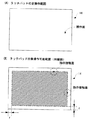
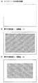
図11(A)および図11(B)から分かるように、指の接触面の面積が小さいほど、タッチパッドの端(縁)により近い位置までドラッグ(タッチ)することができる。逆に、指の接触面の面積が大きいほど、タッチパッドの端に近い位置をタッチするのが困難である。したがって、タッチパッドの全操作範囲が図12(A)に示すような範囲である場合には、たとえば、接触面が小さいときには、図12(B)の斜線で示す範囲(操作可能範囲I)を操作することができ、接触面が大きいときには、図12(C)の斜線で示す範囲(操作可能範囲II)を操作することができる。つまり、人物毎や同じ人物であっても操作時毎に操作可能範囲が異なるという問題が生じてしまう。 As can be seen from FIGS. 11A and 11B, the smaller the area of the contact surface of the finger, the closer to the edge (edge) of the touchpad, the more dragging (touching) is possible. Conversely, the larger the area of the finger contact surface, the more difficult it is to touch a position closer to the end of the touch pad. Therefore, when the entire operation range of the touch pad is in a range as shown in FIG. 12A, for example, when the contact surface is small, the range indicated by the oblique lines in FIG. When the contact surface is large, the range (operable range II) indicated by the oblique lines in FIG. 12C can be operated. That is, there arises a problem that the operable range is different for each person or even for the same person.
このため、たとえば、タッチパッドをゲーム機のジョイスティックコントローラの代わりに使用すると、そのタッチ操作可能な範囲の違いにより、プレイヤキャラクタの移動範囲や移動速度の制御にばらつきが発生してしまうという問題がある。 For this reason, for example, when the touch pad is used instead of the joystick controller of the game machine, there is a problem that variation in the movement range and movement speed of the player character occurs due to the difference in the touch operable range. .
それゆえに、この発明の主たる目的は、新規な、ポインティングデバイスの入力調整プログラムおよび入力調整装置を提供することである。 SUMMARY OF THE INVENTION Therefore, a main object of the present invention is to provide a novel pointing device input adjustment program and input adjustment device.
この発明の他の目的は、使用者や使用者の操作の仕方に拘わらず、安定した入力を行うことができる、ポインティングデバイスの入力調整プログラムおよび入力調整装置を提供することである。 Another object of the present invention is to provide an input adjustment program and an input adjustment apparatus for a pointing device, which can perform stable input regardless of a user or a user's operation method.
本発明は、上記の課題を解決するために、以下の構成を採用した。なお、括弧内の参照符号および補足説明等は、本発明の理解を助けるために後述する実施形態との対応関係の一例を示したものであって、本発明を何ら限定するものではない。 The present invention employs the following configuration in order to solve the above problems. Note that the reference numerals in parentheses, supplementary explanations, and the like are examples of the correspondence with the embodiments described later in order to help understanding of the present invention, and do not limit the present invention.
請求項1の発明は、操作面を有し、この操作面に対してタッチ操作されたときのタッチ座標およびタッチ面積に応じた値を入力する平面型ポインティングデバイスの入力調整プログラムであって、コンピュータに、補正値算出ステップ、第1範囲算出ステップ、倍率算出ステップ、および距離補正ステップを実行させる。補正値算出ステップは、平面型ポインティングデバイスから入力されるタッチ面積に応じた値を接触面積とみなし、そのタッチ面積を正円の面積と擬制した場合の当該正円の半径に応じた補正値を算出する。第1範囲算出ステップは、補正値算出ステップによって算出された補正値を用いて、ユーザが実際に操作した際にタッチ座標が取り得る第1範囲を算出する。倍率算出ステップは、第1範囲算出ステップによって算出された第1範囲を、操作面全体の第2範囲に一致させるための倍率を算出する。そして、距離補正ステップは、倍率算出ステップによって算出された倍率で基準点から現在のタッチ座標までの距離を補正する距離補正ステップを実行させる。
The invention of
請求項1の発明では、平面型ポインティングデバイスの入力調整プログラムは、コンピュータ(12:実施例で相当する参照符号。以下、同じ。)によって実行される。この平面型ポインティングデバイス(14)は、操作面を有し、この操作面を使用者(ユーザ)が指でタッチすると、そのタッチ位置であるタッチ座標および指と操作面との接触面のタッチ面積に応じた値を入力する。つまり、コンピュータ(12)に与える。ここで、タッチ面積に応じた値とは、タッチ面積の増減に従って変化する数値を示し、たとえば静電式タッチパッドの場合にはタッチ面積に応じて増減する静電容量を示す。入力調整プログラムは、コンピュータ(12)に、補正値算出ステップ(S7)、第1範囲算出ステップ(S23)、倍率算出ステップ(S25)、および距離補正ステップ(S27)を実行させる。補正値算出ステップ(S7)は、平面型ポインティングデバイス(14)から入力されるタッチ面積に応じた値をタッチ面積とみなし、タッチ面積を正円の面積と擬制した場合の当該正円の半径に応じた補正値を算出する。ここで、半径に応じた補正値とは、円の半径の長短に応じて変化する数値を示し、例えば円の半径そのものの数値や面積の平方根の数値が相当する。第1範囲算出ステップ(S23)は、補正値算出ステップによって算出された補正値を用いて、ユーザの指によって操作をできない可能性がある範囲を除いた第1範囲を算出する。倍率算出ステップ(S25)は、第1範囲算出ステップ(S23)によって算出された第1範囲を、操作面全体の第2範囲に一致させるための倍率を算出する。そして、距離補正ステップ(S27)は、倍率算出ステップ(S25)によって算出された倍率で基準点から現在のタッチ座標までの距離(移動量)を補正する距離補正ステップを実行させる。 According to the first aspect of the present invention, the input adjustment program for the planar pointing device is executed by a computer (12: reference numeral corresponding to the embodiment; the same applies hereinafter). The planar pointing device (14) has an operation surface. When a user (user) touches the operation surface with a finger, the touch coordinates that are the touch position and the touch area of the contact surface between the finger and the operation surface are displayed. Enter a value according to. That is, it gives to a computer (12). Here, the value corresponding to the touch area indicates a numerical value that changes as the touch area increases or decreases. For example, in the case of an electrostatic touch pad, the value indicates a capacitance that increases or decreases according to the touch area. The input adjustment program causes the computer (12) to execute a correction value calculation step (S7), a first range calculation step (S23), a magnification calculation step (S25), and a distance correction step (S27). In the correction value calculation step (S7), a value corresponding to the touch area input from the planar pointing device (14) is regarded as the touch area, and the radius of the true circle when the touch area is assumed to be a true circle area is assumed. The corresponding correction value is calculated. Here, the correction value corresponding to the radius indicates a numerical value that changes according to the length of the circle radius, and corresponds, for example, to the numerical value of the radius of the circle itself or the numerical value of the square root of the area. In the first range calculation step (S23), the first range is calculated using the correction value calculated in the correction value calculation step, excluding the range in which the user's finger may not be able to operate. The magnification calculation step (S25) calculates a magnification for making the first range calculated in the first range calculation step (S23) coincide with the second range of the entire operation surface. Then, the distance correction step (S27) executes a distance correction step of correcting the distance (movement amount) from the reference point to the current touch coordinates with the magnification calculated in the magnification calculation step (S25).
請求項1の発明によれば、実際に操作可能な範囲をタッチパッドの全操作範囲に一致させる倍率で、基準点から現在のタッチ座標までの距離を補正するので、各ユーザやユーザのタッチの仕方に拘わらず、安定した入力を行うことができる。 According to the first aspect of the present invention, the distance from the reference point to the current touch coordinates is corrected at a magnification that matches the actual operable range with the entire operation range of the touchpad. Regardless of the method, stable input can be performed.
請求項2の発明は請求項1に従属し、基準点は操作面に対してタッチオンしたときのタッチ座標であり、操作面の中心点に対する基準点の横方向のずれおよび縦方向のずれの少なくとも一方を補正する基準点補正ステップをさらに実行させる。
The invention of claim 2 is dependent on
請求項2の発明では、基準点は、ユーザが操作面に対してタッチオンしたときのタッチ座標である。基準点補正ステップ(S11,S13,S15,S17,S19,S21)は、操作面の中心点(原点)に対する基準点の横方向(X軸方向)のずれおよび縦方向(Y軸方向)のずれの少なくとも一方を補正する。 In the invention of claim 2, the reference point is a touch coordinate when the user touches on the operation surface. In the reference point correction steps (S11, S13, S15, S17, S19, S21), the lateral deviation (X-axis direction) and the longitudinal deviation (Y-axis direction) of the reference point with respect to the center point (origin) of the operation surface. Correct at least one of the following.
請求項2の発明によれば、基準点を原点に一致させるように補正するので、基準点のずれを吸収して安定した入力を行うことができる。 According to the second aspect of the invention, since the reference point is corrected so as to coincide with the origin, the deviation of the reference point can be absorbed and stable input can be performed.
請求項3の発明は、操作面を有し、この操作面に対してタッチ操作されたときのタッチ座標およびタッチ面積に応じた値を入力する平面型ポインティングデバイスの入力調整プログラムであって、コンピュータに、補正値算出ステップ、第1範囲算出ステップ、倍率算出ステップ、座標補正ステップを実行させる。補正値算出ステップは、タッチ面積を正円の面積とみなし、タッチ面積に応じた値を用いて当該正円の半径に応じた補正値を算出する。第1範囲算出ステップは、補正値算出ステップによって算出された補正値に応じた距離だけ、操作面全体を中心方向に縮めた第1範囲を算出する。倍率算出ステップは、第1範囲算出ステップによって算出された第1範囲を、操作面全体に対応させるための拡大率を算出する。座標補正ステップは、倍率算出ステップによって算出された倍率によって第1範囲におけるタッチ座標を拡大補正することにより、第1範囲におけるタッチ座標を前記操作面全体におけるタッチ座標に変換する。
The invention of
請求項3の発明では、平面型ポインティングデバイスの入力調整プログラムは、コンピュータ(12)によって実行される。この平面型ポインティングデバイス(14)は、操作面を有し、この操作面をユーザが指でタッチすると、そのタッチした指が操作面に接触する位置のタッチ座標および接触面のタッチ面積に応じた値をコンピュータ(12)に与える。入力調整プログラムは、コンピュータ(12)に、補正値算出ステップ(S7)、第2範囲算出ステップ(S23)、倍率算出ステップ(S25)、および座標補正ステップ(S28)を実行させる。補正値算出ステップ(S7)は、タッチ面積が正円の面積に等しいとみなし、平面型ポインティングデバイス(14)から入力されるタッチ面積に応じた値を用いて当該正円の半径に応じた補正値を算出する。第1範囲算出ステップ(S23)は、補正値算出ステップによって算出された補正値に応じた距離だけ、操作面全体を中心方向に縮めた第1範囲を算出する。倍率算出ステップ(S25)は、第1範囲算出ステップ(S23)によって算出された第1範囲を、操作面全体の第2範囲に対応させるための倍率を算出する。そして、座標補正ステップ(S28)は、倍率算出ステップ(S25)によって算出された倍率によって第1範囲におけるタッチ座標を第2範囲(操作面全体)におけるタッチ座標に変換する補正ステップを実行させる。
In the invention of
請求項3の発明によれば、実際に操作可能な範囲をタッチパッドの全操作範囲に一致させる倍率で、現在のタッチ座標を補正するので、各ユーザやユーザのタッチの仕方に拘わらず、安定した入力を行うことができる。 According to the third aspect of the present invention, the current touch coordinates are corrected at a magnification that matches the actual operable range with the entire operation range of the touchpad. Input can be made.
請求項4の発明は、平面型ポインティングデバイス、補正値算出手段、第1範囲算出手段、倍率算出手段、および距離補正手段を備える平面型ポインティングデバイスの入力調整装置である。平面型ポインティングデバイスは、操作面を有し、この操作面に対するタッチ座標およびタッチ面積に応じた値を入力する。補正値算出手段は、平面型ポインティングデバイスから入力されるタッチ面積に応じた値をタッチ面積とみなし、タッチ面積を正円の面積と擬制した場合の当該正円の半径に応じた補正値を算出する。第1範囲算出手段は、補正値算出手段によって算出された補正値を用いて、ユーザが実際に操作した際にタッチ座標が取り得る第1範囲を算出する。倍率算出手段は、第1範囲算出手段によって算出された第1範囲を、操作面全体の第2範囲に一致させるための倍率を算出する。そして、距離補正手段は、倍率算出手段によって算出された倍率で基準点から現在のタッチ座標までの距離を補正する。 According to a fourth aspect of the present invention, there is provided an input adjustment device for a flat pointing device comprising a flat pointing device, a correction value calculating means, a first range calculating means, a magnification calculating means, and a distance correcting means. The planar pointing device has an operation surface, and inputs values corresponding to touch coordinates and a touch area on the operation surface. The correction value calculation means regards the value corresponding to the touch area input from the flat pointing device as the touch area, and calculates the correction value according to the radius of the true circle when the touch area is assumed to be a true circle area. To do. The first range calculation means calculates a first range that the touch coordinates can take when the user actually operates using the correction value calculated by the correction value calculation means. The magnification calculating unit calculates a magnification for making the first range calculated by the first range calculating unit coincide with the second range of the entire operation surface. The distance correction unit corrects the distance from the reference point to the current touch coordinates with the magnification calculated by the magnification calculation unit.
請求項4の発明においても、請求項1の発明と同様に、各ユーザやユーザのタッチの仕方に拘わらず、安定した入力を行うことができる。
In the invention of claim 4 as well, similarly to the invention of
請求項5の発明は請求項4に従属し、基準点は操作面に対してタッチオンしたときのタッチ座標であり、操作面の中心点に対する基準点の横方向のずれおよび縦方向のずれの少なくとも一方を補正する基準点補正手段をさらに実行させる。
The invention according to
請求項5の発明においても、請求項2の発明と同様に、基準点のずれを吸収して安定した入力を行うことができる。
In the invention of
請求項6の発明は、平面型ポインティングデバイス、補正値算出手段、第1範囲算出手段、倍率算出手段、および座標補正手段を備える平面型ポインティングデバイスの入力調整装置である。平面型ポインティングデバイスは、操作面を有し、この操作面に対してタッチ操作されたときのタッチ座標およびタッチ面積に応じた値を入力する。補正値算出手段は、タッチ面積を正円の面積とみなし、当該タッチ面積に応じた値を用いて当該正円の半径に応じた補正値を算出する。第1範囲算出手段は、補正値算出手段によって算出された補正値に応じた距離だけ、操作面全体を中心方向に縮めた第1範囲を算出する。倍率算出手段は、第1範囲算出手段によって算出された第1範囲を、操作面全体の第2範囲に対応させるための拡大率を算出する。そして、座標補正手段は、倍率算出手段によって算出された拡大率によって第1範囲におけるタッチ座標を拡大補正することにより、当該第1範囲におけるタッチ座標を第2範囲におけるタッチ座標に変換する。 A sixth aspect of the present invention is an input adjustment device for a flat pointing device including a flat pointing device, a correction value calculating means, a first range calculating means, a magnification calculating means, and a coordinate correcting means. The flat pointing device has an operation surface, and inputs values corresponding to touch coordinates and a touch area when a touch operation is performed on the operation surface. The correction value calculation means regards the touch area as an area of a perfect circle, and calculates a correction value according to the radius of the true circle using a value corresponding to the touch area. The first range calculation unit calculates a first range in which the entire operation surface is contracted in the center direction by a distance corresponding to the correction value calculated by the correction value calculation unit. The magnification calculating unit calculates an enlargement ratio for causing the first range calculated by the first range calculating unit to correspond to the second range of the entire operation surface. The coordinate correcting unit converts the touch coordinates in the first range into touch coordinates in the second range by correcting the touch coordinates in the first range with the enlargement ratio calculated by the magnification calculating unit.
請求項6の発明においても、請求項3の発明と同様に、安定した入力を行うことができる。
In the invention of claim 6, as in the invention of
この発明によれば、実際に操作可能な範囲をタッチパッドの全操作範囲に一致させる倍率で、基準点から現在のタッチ座標までの距離を補正するので、各ユーザやユーザのタッチの仕方に拘わらず、安定した入力を行うことができる。 According to the present invention, the distance from the reference point to the current touch coordinates is corrected at a magnification that matches the actual operable range with the entire operation range of the touchpad. Therefore, stable input can be performed.
この発明の上述の目的,その他の目的,特徴および利点は、図面を参照して行う以下の実施例の詳細な説明から一層明らかとなろう。 The above object, other objects, features and advantages of the present invention will become more apparent from the following detailed description of embodiments with reference to the drawings.
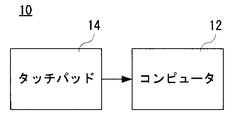
図1を参照して、この発明の一実施例である入力装置10はコンピュータ12を含み、コンピュータ12にはタッチパッド14が接続される。コンピュータ12は、典型的にはマイクロコンピュータであり、タッチパッド14の入力調整プログラムを記憶し、入力調整装置として機能する。このコンピュータ12には、図示しない電子機器が接続される。たとえば、電子機器としては、パーソナルコンピュータ、ワークステーション、PDA、ゲーム機、ゲーム機のコントローラなどが該当する。ただし、コンピュータ12または/およびタッチパッド14が電子機器に内蔵される場合もある。
Referring to FIG. 1, an
タッチパッド(ないしタッチパネル)14は、ユーザが指で操作面であるパッド表面を触れると、指がパッド表面に接触する位置に応じたタッチ座標とタッチ面積に応じた値をコンピュータ12に与える。たとえば、タッチ座標の一例としては、指が操作面に接触する面(接触面)の重心の座標のデータ(座標データ)である。また、タッチ面積に応じた値の一例としては、接触面の面積に応じた静電容量である。これらの値は、タッチパッド14側のASICなどによって演算された結果に出力される値であり、たとえば、タッチパッド14としては、Synaptics社製のタッチパッド(http://www.synaptics.com/technology/cps.cfm)を用いることができる。なお、上述したように、重心の座標データや静電容量は一例であり、タッチ座標としてはタッチ位置によって決まる座標であればよく、タッチ面積(接触面の面積)に応じた値としては接触面の面積の増減に応じて増減するような値であればよい。したがって、静電式のタッチパッド14だけでなく、光学式などの任意の種類のタッチパッド(タッチパネル)を用いることができる。
When the user touches the pad surface that is the operation surface with a finger, the touch pad (or touch panel) 14 gives the
コンピュータ12は、タッチパッド14から与えられる座標データおよび静電容量に、演算処理(調整処理を含む。)を施した入力データを電子機器に入力する。ただし、コンピュータ12は、座標データおよび静電容量をそのまま電子機器に入力することもある。たとえば、電子機器としてのパーソナルコンピュータでは、入力データを受けて、画面上のカーソル(マウスポインタ)やアイコンなどの任意の画像を移動させたり、画面をスクロールさせたりする。また、電子機器としてのゲーム機では、入力データを受けて、プレイヤキャラクタの移動を制御したり、その移動速度を制御したりする。
The
通常、タッチパッド14は、図2(A)に示すように、その表面(パッド表面)の全体が操作面(全操作範囲)である。しかし、タッチパッド14では、指の接触面の重心の座標データを出力するようにしてあるため、指でタッチする場合には、実際には、パッド表面の端(縁)までを操作範囲として用いることができない。たとえば、タッチパッド14の周囲(外周)に枠が設けられる場合には、タッチパッド14の外周付近では、その枠により指の移動が規制されたり、ユーザはタッチパッド14の枠を指の感触により認識したりして、ドラッグを止める。したがって、図2(B)に示すように、指の接触面の重心(中心)から一定距離(ここでは、接触面の形状が正円とみなした場合の正円の半径rに応じた補正値r´)に相当する長さだけ、上下および左右のドラッグ可能な範囲(操作可能範囲)が小さくされる。また、各ユーザやユーザのタッチの仕方に応じて、相対的にまたは絶対的に接触面の大きさが異なるため、実際の操作可能範囲(実操作可能範囲)にばらつきが発生してしまう。
Normally, as shown in FIG. 2A, the entire surface (pad surface) of the
そこで、この実施例では、かかるばらつきを無くすために、指の接触面の大きさに基づいて、実操作可能範囲を全操作範囲に一致させるように補正するようにしてある。以下、具体的に説明することにする。 Therefore, in this embodiment, in order to eliminate such variations, correction is performed so that the actual operation possible range matches the entire operation range based on the size of the contact surface of the finger. A specific description will be given below.
たとえば、コンピュータ12は、使用者ないしユーザがタッチパッド14にタッチオンしたときのタッチ座標を基準点(基準位置)とし、つまり基準位置として記憶しておき、その後、ドラッグ操作によってタッチ座標が入力されると、当該基準位置に対する現在のタッチ座標の差分を求めて、X成分の移動量やY成分の移動量を電子機器(図示せず)に入力するようにしてある。なお、この実施例では、簡単のため、基準位置は固定するようにしてあるが、時間の経過に従って、タッチパッド14の中心位置に近づけるようにしてもよい。
For example, the
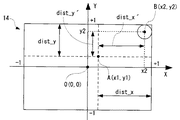
また、基準位置はタッチパッド14の全操作範囲の中心と一致しないことがあるため、現在のタッチ座標と基準位置との関係から、タッチ座標が取り得る横方向(X軸方向)の範囲(最大値)および縦方向(Y軸方向)の最大値を求めるようにしてある。この実施例では、X軸方向の最大値を変数dist_xで表わし、Y軸方向の最大値を変数dist_yで表わすようにしてある。ただし、変数dist_xおよび変数dist_yは、いずれも絶対値である。また、この例では、タッチパッド14の中心位置を原点とし、第1象限,第2象限,第3象限および第4象限に分けて考えるようにしてあるため、基準位置との関係で、変数dist_x,dist_yも適宜決定される。さらに、図3(図4も同様)では、点線の円がタッチオン時のタッチ座標における指の接触形状(接触面)を示し、実線の円が現在のタッチ位置における指の接触形状(接触面)を示している。
In addition, since the reference position may not coincide with the center of the entire operation range of the
まず、図3(A)に示すように、基準位置A(x1,y1)よりも現在のタッチ位置B(x2,y2)が右側である場合には、つまりx2≧x1である場合には、X軸方向の最大値すなわち変数dist_xは数1で示される。
First, as shown in FIG. 3A, when the current touch position B (x2, y2) is on the right side of the reference position A (x1, y1), that is, when x2 ≧ x1, The maximum value in the X-axis direction, that is, the variable dist_x is expressed by
[数1]
dist_x = 1−x1
また、図3(B)に示すように、基準位置A(x1,y1)よりも現在のタッチ位置B(x2,y2)が左側である場合には、つまりx2<x1である場合には、X軸方向の最大値すなわち変数dist_xは数2で示される。
[Equation 1]
dist_x = 1-x1
As shown in FIG. 3B, when the current touch position B (x2, y2) is on the left side of the reference position A (x1, y1), that is, when x2 <x1, The maximum value in the X-axis direction, that is, the variable dist_x is expressed by Equation 2.
[数2]
dist_x = 1+x1
図4(A)に示すように、基準位置A(x1,y1)よりも現在のタッチ位置B(x2,y2)が上側である場合には、つまりy1≧y2である場合には、Y軸方向の最大値すなわち変数dist_yは数3で示される。
[Equation 2]
dist_x = 1 + x1
As shown in FIG. 4A, when the current touch position B (x2, y2) is above the reference position A (x1, y1), that is, when y1 ≧ y2, the Y axis The maximum value of the direction, that is, the variable dist_y is expressed by
[数3]
dist_y = 1−y1
また、図4(B)に示すように、基準位置A(x1,y1)よりも現在のタッチ位置B(x2,y2)が下側である場合には、つまりy1<y2である場合には、Y軸方向の最大値すなわち変数dist_yは数4で示される。
[Equation 3]
dist_y = 1-y1
Further, as shown in FIG. 4B, when the current touch position B (x2, y2) is below the reference position A (x1, y1), that is, when y1 <y2. , The maximum value in the Y-axis direction, that is, the variable dist_y is expressed by Equation 4.
[数4]
dist_y = 1+y1
このようにして、基準位置Aと現在のタッチ位置Bとの相対位置に応じて、X軸方向およびY軸方向の最大値がそれぞれ決定される。ただし、図2(B)に示したように、タッチパッド14のパッド表面の外周近傍は実質的に操作できない領域となる。したがって、この領域に対応する長さを、X軸方向の最大値およびY軸方向の最大値のそれぞれから削除(減算)するようにしてある。
[Equation 4]
dist_y = 1 + y1
In this way, the maximum values in the X-axis direction and the Y-axis direction are determined according to the relative position between the reference position A and the current touch position B, respectively. However, as shown in FIG. 2B, the vicinity of the outer periphery of the pad surface of the
具体的には、計算式を容易にし、計算負荷を軽減するために指の接触面を正円とみなし、当該正円の半径rに応じた補正値r´を数5に従って求めて、数6に示すように、この補正値r´をそれぞれの最大値から減算した実際の最大値(dist_x´,dist_y´)を求める。
Specifically, in order to facilitate the calculation formula and reduce the calculation load, the contact surface of the finger is regarded as a perfect circle, and a correction value r ′ corresponding to the radius r of the perfect circle is obtained according to
ただし、数5において、Sは接触面の面積とみなした静電容量であり、タッチパッド14から与えられる静電容量に対応する。また、数5において、kは或る係数であり、この実施例の入力調整プログラムや入力調整装置のプログラマないし設計者によって決定される。
However, in
[数5]
r´=k×√S
[数6]
dist_x´ = dist_x−r´
dist_y´ = dist_y−r´
なお、数5では、本来の円の公式(r=√(S/π))を用いずに、補正値r´を求めるようにしてあるが、これは計算負荷を軽減するためである。したがって、計算負荷を考慮しない場合には、円の公式に従って半径rを求めて、この半径rを数6で用いるようにしてもよい。
[Equation 5]
r ′ = k × √S
[Equation 6]
dist_x ′ = dist_x−r ′
dist_y ′ = dist_y−r ′
In
したがって、たとえば、現在タッチパッド14の右上をタッチしており、そのタッチ位置が基準位置よりも右側であり、かつ上側である場合には、実際の最大値(dist_x´,dist_y´)は図5のように示される。
Therefore, for example, when the upper right of the
ここで、図3および図4に示すように、実際の最大値(dist_x´,dist_y´)は、タッチパッド14の全操作範囲(この実施例では、−1≦x≦1,−1≦y≦1)に一致するように、その倍率(scale_x,scale_y)が数7に従って決定される。つまり、実操作可能範囲を全操作範囲に一致させるための倍率(拡大率)が算出される。
Here, as shown in FIGS. 3 and 4, the actual maximum value (dist_x ′, dist_y ′) is the entire operation range of the touch pad 14 (in this embodiment, −1 ≦ x ≦ 1, −1 ≦ y). The magnification (scale_x, scale_y) is determined according to
[数7]
scale_x = 1÷dist_x´
scale_y = 1÷dist_y´
したがって、実際の電子機器への入力データ(移動量(距離)データ)は、数8に従って算出される。
[Equation 7]
scale_x = 1 ÷ dist_x ′
scale_y = 1 ÷ dist_y ′
Therefore, the actual input data (movement amount (distance) data) to the electronic device is calculated according to Equation 8.
[数8]
入力データのX成分=(x2−x1)×scale_x
入力データのY成分=(y2−y1)×scale_y
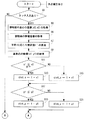
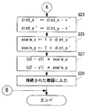
具体的には、図1に示したコンピュータ12は図6および図7に示すデータ入力処理を実行する。図6を参照して、コンピュータ12はデータ入力処理を開始すると、ステップS1で、タッチ入力があるかどうかを判断する。具体的には、タッチパッド14から座標データおよび面積データが与えられているかどうかを判断する。ステップS1で“NO”であれば、つまりタッチ入力がなければ、図7に示すように、そのままデータ入力処理を終了する。
[Equation 8]
X component of input data = (x2−x1) × scale_x
Y component of input data = (y2−y1) × scale_y
Specifically, the
しかし、ステップS1で“YES”であれば、つまりタッチ入力があれば、ステップS3で、接触面の重心の座標すなわち現在のタッチ座標(x2,y2)を取得し、ステップS5で、接触面の静電容量Sを取得する。つまり、タッチパッド14から与えられた座標データに基づいて現在のタッチ座標(x2,y2)を取得し、タッチパッド14から与えられた静電容量に基づいて静電容量Sを取得する。
However, if “YES” in step S1, that is, if there is a touch input, in step S3, the coordinates of the center of gravity of the contact surface, that is, the current touch coordinates (x2, y2) are acquired, and in step S5, the contact surface Capacitance S is acquired. That is, the current touch coordinates (x2, y2) are acquired based on the coordinate data given from the
続くステップS7では、接触面の形状を正円(真ん丸)とみなして、当該正円の半径rに応じた補正値r´を数5に従って算出する。続くステップS9では、基準点の座標(x1,y1)を取得する。ただし、基準点の座標(x1,y1)は、タッチオン座標であり、ステップS1で最初に“YES”と判断されたときに、ステップS3で取得される座標(x2,y2)である。
In subsequent step S7, the shape of the contact surface is regarded as a perfect circle (true circle), and a correction value r ′ corresponding to the radius r of the true circle is calculated according to
続いて、ステップS11では、x1≦x2であるかどうかを判断する。つまり、基準点のx座標が現在のタッチ座標のx座標以下であるかどうかを判断する。ステップS11で“YES”であれば、つまりx1≦x2であれば、ステップS13で、変数dist_xに1−x1を代入して、ステップS17に進む。一方、ステップS11で“NO”であれば、つまりx1>x2であれば、ステップS15で、変数dist_xに1+x1を代入して、ステップS17に進む。 Subsequently, in step S11, it is determined whether x1 ≦ x2. That is, it is determined whether the x coordinate of the reference point is equal to or less than the x coordinate of the current touch coordinate. If “YES” in the step S11, that is, if x1 ≦ x2, in a step S13, 1−x1 is substituted for the variable dist_x, and the process proceeds to a step S17. On the other hand, if “NO” in the step S11, that is, if x1> x2, in a step S15, 1 + x1 is substituted for the variable dist_x, and the process proceeds to the step S17.
ステップS17では、y1≦y2であるかどうかを判断する。つまり、基準点のy座標が現在のタッチ座標のy座標以下であるかどうかを判断する。ステップS17で“YES”であれば、つまりy1≦y2であれば、ステップS19で、変数dist_yに1−y1を代入して、図7に示すステップS23に進む。一方、ステップS17で“NO”であれば、つまりy1>y2であれば、ステップS21で、変数dist_yに1+y1を代入して、ステップS23に進む。 In step S17, it is determined whether y1 ≦ y2. That is, it is determined whether the y coordinate of the reference point is equal to or less than the y coordinate of the current touch coordinate. If “YES” in the step S17, that is, if y1 ≦ y2, 1-y1 is substituted for the variable dist_y in a step S19, and the process proceeds to a step S23 shown in FIG. On the other hand, if “NO” in the step S17, that is, if y1> y2, 1 + y1 is substituted for the variable dist_y in a step S21, and the process proceeds to the step S23.
なお、ステップS11〜S21の処理によって、原点と基準点とのずれが補正されるのである。 Note that the deviation between the origin and the reference point is corrected by the processing in steps S11 to S21.
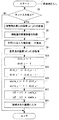
図7に示すように、ステップS23では、変数dist_x´にdist_x−r´を代入し、変数dist_y´にdist_y−r´を代入する。続くステップS25では、変数scale_xに1÷dist_x´を代入し、変数scale_yに1÷dist_y´を代入する。つまり、拡大率が算出される。そして、ステップS27で、入力データを算出する。具体的には、(x2−x1)×scale_xにより、入力データのx成分を算出し、(y2−y1)×scale_yにより、入力データのy成分を算出する。そして、ステップS29で、接続された電子機器に入力データを入力して、データ入力処理を終了する。 As shown in FIG. 7, in step S23, dist_x-r 'is substituted for variable dist_x', and dist_y-r 'is substituted for variable dist_y'. In the subsequent step S25, 1 / dist_x 'is substituted for the variable scale_x, and 1 / dist_y' is substituted for the variable scale_y. That is, the enlargement ratio is calculated. In step S27, input data is calculated. Specifically, the x component of the input data is calculated from (x2−x1) × scale_x, and the y component of the input data is calculated from (y2−y1) × scale_y. In step S29, input data is input to the connected electronic device, and the data input process is terminated.
なお、上述したデータ入力処理は一定時間(たとえば、1フレーム(1/60秒))毎に実行される。 Note that the above-described data input process is executed every certain time (for example, one frame (1/60 second)).
この実施例によれば、接触面の静電容量から実操作可能範囲を割り出し、実操作可能範囲をタッチパッドの操作可能範囲に一致させるように調整するので、相対的および絶対的な操作可能範囲の差を無くして、安定した入力操作を行うことができる。 According to this embodiment, the actual operable range is determined from the capacitance of the contact surface, and the actual operable range is adjusted to match the operable range of the touchpad. Thus, a stable input operation can be performed.
なお、上述の実施例では、図6および図7に示したように、データ入力処理において、基準点と原点とのずれを補正するようにしたが、当該ずれを補正しない場合であっても、比較的安定した入力操作を行うことが可能である。かかる場合には、図8に示すようなデータ入力処理が実行される。図8に示すデータ入力処理は、図6および図7に示したデータ入力処理のうち、ステップS11〜S21を削除し、ステップS9とステップS23との間に、ステップS10を設けた以外は、図6および図7に示したデータ入力処理と同じである。ステップS10では、変数dist_xおよび変数dist_yのそれぞれに「1」を代入するようにしてある。 In the above-described embodiment, as shown in FIGS. 6 and 7, in the data input process, the deviation between the reference point and the origin is corrected. However, even if the deviation is not corrected, A relatively stable input operation can be performed. In such a case, a data input process as shown in FIG. 8 is executed. The data input process shown in FIG. 8 is the same as the data input process shown in FIGS. 6 and 7 except that steps S11 to S21 are deleted and step S10 is provided between steps S9 and S23. 6 and the data input process shown in FIG. In step S10, “1” is assigned to each of the variable dist_x and the variable dist_y.
ただし、かかる場合には、変数dist_xおよび変数dist_yは、定数となるため、ステップS23における変数dist_xおよび変数dist_yのそれぞれを「1」にすることにより、ステップS10の処理を省略することも可能である。 However, in such a case, since the variable dist_x and the variable dist_y are constants, the processing in step S10 can be omitted by setting each of the variable dist_x and the variable dist_y in step S23 to “1”. .
また、上述の実施例では、ユーザが最初にタッチオンしたタッチ位置を基準点に決定し、当該基準点と現在のタッチ位置との距離を補正するようにしたが、基準点に拘わらず、現在のタッチ位置(タッチ座標)を補正するようにすることもできる。ただし、かかる場合には、原点は操作面の中心点や操作面のいずれかの頂点などに固定的に設定すればよく、その原点に対する相対的なタッチ座標が検出されるだけであるため、原点の補正処理は不要である。 Further, in the above-described embodiment, the touch position where the user first touched on is determined as the reference point, and the distance between the reference point and the current touch position is corrected. It is also possible to correct the touch position (touch coordinates). However, in such a case, the origin should be fixedly set at the center point of the operation surface or any vertex of the operation surface, and only the touch coordinates relative to the origin are detected. This correction process is unnecessary.
かかる場合には、コンピュータ12は、図9に示すフロー図に従ってデータ入力処理を実行する。ただし、図8に示したデータ入力処理とほぼ同じであるため、同じ処理には同じ参照符号(ステップ番号)を付し、その詳細な説明は省略することにする。
In such a case, the
具体的には、図9に示すデータ入力処理は、図8に示したデータ入力処理において、ステップS9を削除し、ステップS27に変えてステップS28を設けてある。つまり、基準点の座標を検出する必要がなく、ステップS25で、拡大率(scale_x,scale_y)を算出すると、ステップS28で、現在のタッチ座標(x2,y2)を補正する。ただし、補正後のタッチ座標(x´,y´)は、数9に従って算出される。
Specifically, in the data input process shown in FIG. 9, step S9 is deleted in the data input process shown in FIG. 8, and step S28 is provided instead of step S27. That is, it is not necessary to detect the coordinates of the reference point, and when the enlargement ratio (scale_x, scale_y) is calculated in step S25, the current touch coordinates (x2, y2) are corrected in step S28. However, the corrected touch coordinates (x ′, y ′) are calculated according to
[数9]
x´=x2×scale_x
y´=y2×scale_y
このように、補正したタッチ座標を入力データとして、コンピュータ12に接続された電子機器に入力することもできる。かかる場合にも、相対的および絶対的な操作可能範囲の差を無くして、安定した入力操作を行うことができる。
[Equation 9]
x ′ = x2 × scale_x
y ′ = y2 × scale_y
In this way, the corrected touch coordinates can be input as input data to an electronic device connected to the
10 …入力装置
12 …コンピュータ
14 …タッチパッド
10 ...
Claims (6)
コンピュータに、
前記平面型ポインティングデバイスから入力されるタッチ面積に応じた値をタッチ面積とみなし、当該タッチ面積を正円の面積と擬制した場合の当該正円の半径に応じた補正値を算出する補正値算出ステップ、
前記補正値算出ステップによって算出された補正値を用いて、前記タッチ座標が取り得る第1範囲を算出する第1範囲算出ステップ、
前記第1範囲算出ステップによって算出された第1範囲を、前記操作面全体の第2範囲に一致させるための倍率を算出する倍率算出ステップ、および
前記倍率算出ステップによって算出された倍率で基準点から現在のタッチ座標までの距離を補正する距離補正ステップを実行させる、ポインティングデバイスの入力調整プログラム。 An input adjustment program for a planar pointing device that has an operation surface and inputs values according to touch coordinates and a touch area when a touch operation is performed on the operation surface.
On the computer,
A correction value calculation that calculates a correction value according to the radius of the true circle when the value corresponding to the touch area input from the planar pointing device is regarded as a touch area and the touch area is assumed to be a true circle area Step,
A first range calculating step of calculating a first range that can be taken by the touch coordinates using the correction value calculated by the correction value calculating step;
A magnification calculation step for calculating a magnification for matching the first range calculated in the first range calculation step with the second range of the entire operation surface, and a reference point with a magnification calculated in the magnification calculation step. Pointing device input adjustment program for executing a distance correction step for correcting the distance to the current touch coordinates.
前記操作面の中心点に対する前記基準点の横方向のずれおよび縦方向のずれの少なくとも一方を補正する基準点補正ステップをさらに実行させる、請求項1記載のポインティングデバイスの入力調整プログラム。 The reference point is a touch coordinate when touching on the operation surface,
The pointing device input adjustment program according to claim 1, further comprising a reference point correction step of correcting at least one of a lateral shift and a vertical shift of the reference point with respect to a center point of the operation surface.
コンピュータに、
前記タッチ面積を正円の面積とみなし、当該タッチ面積に応じた値を用いて当該正円の半径に応じた補正値を算出する補正値算出ステップ、
前記補正値算出ステップによって算出された補正値に応じた距離だけ、前記操作面全体を中心方向に縮めた第1範囲を算出する第1範囲算出ステップ、
前記第1範囲算出ステップによって算出された第1範囲を、前記操作面全体の第2範囲に対応させるための拡大率を算出する倍率算出ステップ、および
前記倍率算出ステップによって算出された拡大率によって前記第1範囲におけるタッチ座標を拡大補正することにより、当該第1範囲におけるタッチ座標を前記第2範囲におけるタッチ座標に変換する座標補正ステップを実行させる、ポインティングデバイスの入力調整プログラム。 An input adjustment program for a planar pointing device that has an operation surface and inputs values according to touch coordinates and a touch area when a touch operation is performed on the operation surface.
On the computer,
A correction value calculating step that regards the touch area as an area of a perfect circle and calculates a correction value according to the radius of the true circle using a value according to the touch area;
A first range calculating step of calculating a first range in which the entire operation surface is contracted in a central direction by a distance corresponding to the correction value calculated in the correction value calculating step;
A magnification calculation step for calculating an enlargement ratio for causing the first range calculated by the first range calculation step to correspond to the second range of the entire operation surface, and the enlargement ratio calculated by the magnification calculation step An input adjustment program for a pointing device that executes a coordinate correction step for converting touch coordinates in the first range into touch coordinates in the second range by performing enlargement correction on the touch coordinates in the first range.
前記平面型ポインティングデバイスから入力されるタッチ面積に応じた値をタッチ面積とみなし、当該タッチ面積を正円の面積と擬制した場合の当該正円の半径に応じた補正値を算出する補正値算出手段、
前記補正値半径算出手段によって算出された補正値を用いて、前記タッチ座標が取り得る第1範囲を算出する第1範囲算出手段、
前記第1範囲算出手段によって算出された第1範囲を、前記操作面全体の第2範囲に一致させるための倍率を算出する倍率算出手段、および
前記倍率算出手段によって算出された倍率で基準点から現在のタッチ座標までの距離を補正する距離補正手段を備える、ポインティングデバイスの入力調整装置。 A planar pointing device that has an operation surface and inputs values corresponding to touch coordinates and a touch area when a touch operation is performed on the operation surface;
A correction value calculation that calculates a correction value according to the radius of the true circle when the value corresponding to the touch area input from the planar pointing device is regarded as a touch area and the touch area is assumed to be a true circle area means,
First range calculating means for calculating a first range that can be taken by the touch coordinates using the correction value calculated by the correction value radius calculating means;
A magnification calculation means for calculating a magnification for matching the first range calculated by the first range calculation means with the second range of the entire operation surface, and a reference point at a magnification calculated by the magnification calculation means. An input adjustment device for a pointing device, comprising distance correction means for correcting a distance to a current touch coordinate.
前記操作面の中心点に対する前記基準点の横方向のずれおよび縦方向のずれの少なくとも一方を補正する基準点補正手段をさらに備える、請求項3記載のポインティングデバイスの入力調整装置。 The reference point is a touch coordinate when touching on the operation surface,
The pointing device input adjustment apparatus according to claim 3, further comprising reference point correction means for correcting at least one of a lateral shift and a vertical shift of the reference point with respect to a center point of the operation surface.
前記タッチ面積を正円の面積とみなし、当該タッチ面積に応じた値を用いて当該正円の半径に応じた補正値を算出する補正値算出手段、
前記補正値算出手段によって算出された補正値に応じた距離だけ、前記操作面全体を中心方向に縮めた第1範囲を算出する第1範囲算出手段、
前記第1範囲算出手段によって算出された第1範囲を、前記操作面全体の第2範囲に対応させるための拡大率を算出する倍率算出手段、および
前記倍率算出手段によって算出された拡大率によって前記第1範囲におけるタッチ座標を拡大補正することにより、当該第1範囲におけるタッチ座標を前記第2範囲におけるタッチ座標に変換する座標補正手段を備える、ポインティングデバイスの入力調整装置。 A planar pointing device that has an operation surface and inputs values corresponding to touch coordinates and a touch area when a touch operation is performed on the operation surface;
A correction value calculating means that regards the touch area as an area of a perfect circle and calculates a correction value according to the radius of the perfect circle using a value according to the touch area.
First range calculating means for calculating a first range in which the entire operation surface is contracted in the central direction by a distance corresponding to the correction value calculated by the correction value calculating means;
Magnification calculation means for calculating an enlargement ratio for causing the first range calculated by the first range calculation means to correspond to the second range of the entire operation surface, and the enlargement ratio calculated by the magnification calculation means An input adjustment device for a pointing device, comprising: coordinate correction means for converting the touch coordinates in the first range into touch coordinates in the second range by enlarging and correcting the touch coordinates in the first range.
Priority Applications (4)
| Application Number | Priority Date | Filing Date | Title |
|---|---|---|---|
| JP2005200618A JP4551830B2 (en) | 2005-07-08 | 2005-07-08 | Pointing device input adjustment program and input adjustment device |
| US11/408,069 US7800593B2 (en) | 2005-07-08 | 2006-04-21 | Storage medium storing pointing device input adjustment program, input adjustment apparatus and input adjustment method |
| EP06113172A EP1741476B1 (en) | 2005-07-08 | 2006-04-26 | Storage medium storing pointing device input adjustment program, input adjustment apparatus and input adjustment method |
| US12/805,748 US8139044B2 (en) | 2005-07-08 | 2010-08-18 | Storage medium storing pointing device input adjustment program, input adjustment apparatus and input adjustment method |
Applications Claiming Priority (1)
| Application Number | Priority Date | Filing Date | Title |
|---|---|---|---|
| JP2005200618A JP4551830B2 (en) | 2005-07-08 | 2005-07-08 | Pointing device input adjustment program and input adjustment device |
Publications (2)
| Publication Number | Publication Date |
|---|---|
| JP2007018372A true JP2007018372A (en) | 2007-01-25 |
| JP4551830B2 JP4551830B2 (en) | 2010-09-29 |
Family
ID=36997627
Family Applications (1)
| Application Number | Title | Priority Date | Filing Date |
|---|---|---|---|
| JP2005200618A Active JP4551830B2 (en) | 2005-07-08 | 2005-07-08 | Pointing device input adjustment program and input adjustment device |
Country Status (3)
| Country | Link |
|---|---|
| US (2) | US7800593B2 (en) |
| EP (1) | EP1741476B1 (en) |
| JP (1) | JP4551830B2 (en) |
Cited By (13)
| Publication number | Priority date | Publication date | Assignee | Title |
|---|---|---|---|---|
| JP2008217704A (en) * | 2007-03-07 | 2008-09-18 | Nec Corp | Display device and portable information equipment |
| JP2010250493A (en) * | 2009-04-14 | 2010-11-04 | Hitachi Displays Ltd | Touch panel device |
| JP2011048663A (en) * | 2009-08-27 | 2011-03-10 | Hitachi Displays Ltd | Touch panel device |
| JP2011237995A (en) * | 2010-05-10 | 2011-11-24 | Fujitsu Toshiba Mobile Communications Ltd | Information processing apparatus |
| JP2013109603A (en) * | 2011-11-22 | 2013-06-06 | Lenovo Singapore Pte Ltd | Input device and portable computer including touchpad |
| JP2013180605A (en) * | 2012-02-29 | 2013-09-12 | Denso Corp | Control device and program |
| WO2014002315A1 (en) * | 2012-06-26 | 2014-01-03 | 株式会社東海理化電機製作所 | Operation device |
| JP2014044697A (en) * | 2012-08-03 | 2014-03-13 | Konami Digital Entertainment Co Ltd | Operation terminal, operation control method, and operation control program |
| JP2014044586A (en) * | 2012-08-27 | 2014-03-13 | Tokai Rika Co Ltd | Operation input device |
| JPWO2012132802A1 (en) * | 2011-03-28 | 2014-07-28 | 富士フイルム株式会社 | Touch panel device, display method thereof, and display program |
| WO2014171177A1 (en) * | 2013-04-19 | 2014-10-23 | シャープ株式会社 | Touch-panel device, display device with touch panel, and program |
| CN105094446A (en) * | 2015-09-01 | 2015-11-25 | 京东方科技集团股份有限公司 | Touch positioning method and apparatus |
| JP2021144763A (en) * | 2016-07-14 | 2021-09-24 | 望月 貴里子 | User interface |
Families Citing this family (25)
| Publication number | Priority date | Publication date | Assignee | Title |
|---|---|---|---|---|
| US20090051671A1 (en) * | 2007-08-22 | 2009-02-26 | Jason Antony Konstas | Recognizing the motion of two or more touches on a touch-sensing surface |
| EP2124117B1 (en) * | 2008-05-21 | 2012-05-02 | Siemens Aktiengesellschaft | Operating device for operating a machine tool |
| JP5205195B2 (en) * | 2008-09-29 | 2013-06-05 | 株式会社日立製作所 | Method of operation |
| JP4650703B2 (en) * | 2008-12-25 | 2011-03-16 | ソニー株式会社 | Display panel, module and electronic device |
| JP5269648B2 (en) * | 2009-03-02 | 2013-08-21 | パナソニック株式会社 | Portable terminal device and input device |
| KR101138622B1 (en) * | 2009-04-14 | 2012-05-16 | 파나소닉 액정 디스플레이 주식회사 | Touch-panel device |
| TWI400638B (en) * | 2009-10-20 | 2013-07-01 | Acer Inc | Touch display device, touch display system, and method for adjusting touch area thereof |
| US8581879B2 (en) | 2010-01-21 | 2013-11-12 | Apple Inc. | Negative pixel compensation |
| TWI433004B (en) * | 2010-05-14 | 2014-04-01 | Alcor Micro Corp | Method for determining touch points on touch panel and system thereof |
| KR101705872B1 (en) * | 2010-09-08 | 2017-02-10 | 삼성전자주식회사 | Method for selecting area on a screen in a mobile device and apparatus therefore |
| JP5313994B2 (en) * | 2010-11-16 | 2013-10-09 | 任天堂株式会社 | Information processing program, information processing apparatus, information processing method, and information processing system |
| DE102010053684A1 (en) * | 2010-12-08 | 2012-06-14 | Trw Automotive Electronics & Components Gmbh | Method for determining a position of a touch on a capacitive sensor field |
| JP5496372B2 (en) * | 2011-02-18 | 2014-05-21 | 三菱電機株式会社 | Coordinate input device and touch panel device |
| US9925464B2 (en) | 2011-03-08 | 2018-03-27 | Nintendo Co., Ltd. | Computer-readable storage medium, information processing system, and information processing method for displaying an image on a display device using attitude data of a display device |
| JP5792971B2 (en) | 2011-03-08 | 2015-10-14 | 任天堂株式会社 | Information processing system, information processing program, and information processing method |
| US9539511B2 (en) | 2011-03-08 | 2017-01-10 | Nintendo Co., Ltd. | Computer-readable storage medium, information processing system, and information processing method for operating objects in a virtual world based on orientation data related to an orientation of a device |
| EP2497543A3 (en) | 2011-03-08 | 2012-10-03 | Nintendo Co., Ltd. | Information processing program, information processing system, and information processing method |
| EP2497547B1 (en) * | 2011-03-08 | 2018-06-27 | Nintendo Co., Ltd. | Information processing program, information processing apparatus, information processing system, and information processing method |
| US9561443B2 (en) | 2011-03-08 | 2017-02-07 | Nintendo Co., Ltd. | Computer-readable storage medium, information processing system, and information processing method |
| US9507454B1 (en) * | 2011-09-19 | 2016-11-29 | Parade Technologies, Ltd. | Enhanced linearity of gestures on a touch-sensitive surface |
| CN102622174B (en) * | 2012-02-23 | 2013-12-11 | 中兴通讯股份有限公司 | Screen unlocking system and method |
| US10126940B2 (en) * | 2014-10-19 | 2018-11-13 | Lenovo (Singapore) Pte. Ltd. | Touch zones on a soft keyboard |
| KR102017073B1 (en) | 2015-10-21 | 2019-09-02 | 한화테크윈 주식회사 | The System And Method For Electrical Power Supply Control |
| JP7377088B2 (en) * | 2019-12-10 | 2023-11-09 | キヤノン株式会社 | Electronic devices and their control methods, programs, and storage media |
| KR20210114643A (en) * | 2020-03-11 | 2021-09-24 | 주식회사 실리콘웍스 | Touch sensing device and touch coordinates detection method thereof |
Citations (7)
| Publication number | Priority date | Publication date | Assignee | Title |
|---|---|---|---|---|
| JPH0683537A (en) * | 1992-09-01 | 1994-03-25 | Ricoh Co Ltd | Touch panel type information processor |
| JPH0883674A (en) * | 1994-09-14 | 1996-03-26 | Dowa Mining Co Ltd | Panel heater and touch panel for flat display and coordinate transformation setting method for touch panel |
| JPH0887380A (en) * | 1994-09-19 | 1996-04-02 | Tabai Espec Corp | Operating body adaptive console panel device |
| JPH09231006A (en) * | 1996-02-28 | 1997-09-05 | Nec Home Electron Ltd | Portable information processor |
| JPH11306933A (en) * | 1998-04-22 | 1999-11-05 | Tokai Rika Co Ltd | Touch operation information output device |
| JP2002055781A (en) * | 2000-08-14 | 2002-02-20 | Canon Inc | Information processor and method for controlling the same and computer readable memory |
| JP2003196031A (en) * | 2001-12-28 | 2003-07-11 | Sharp Corp | Touch panel input device, program, and recording medium recording program |
Family Cites Families (10)
| Publication number | Priority date | Publication date | Assignee | Title |
|---|---|---|---|---|
| JPH06161646A (en) | 1992-11-17 | 1994-06-10 | Oki Electric Ind Co Ltd | Planar pointing device |
| JPH08307954A (en) | 1995-05-12 | 1996-11-22 | Sony Corp | Device and method for coordinate input and information processor |
| JPH1011208A (en) * | 1996-06-24 | 1998-01-16 | Sharp Corp | Coordinate input device |
| JP4294122B2 (en) | 1998-06-23 | 2009-07-08 | アルプス電気株式会社 | Coordinate input device |
| US6346935B1 (en) | 1998-09-14 | 2002-02-12 | Matsushita Electric Industrial Co., Ltd. | Touch-sensitive tablet |
| US6727892B1 (en) | 1999-05-20 | 2004-04-27 | Micron Technology, Inc. | Method of facilitating the selection of features at edges of computer touch screens |
| JP2001265481A (en) * | 2000-03-21 | 2001-09-28 | Nec Corp | Method and device for displaying page information and storage medium with program for displaying page information stored |
| IT1318227B1 (en) | 2000-07-21 | 2003-07-28 | Pirovano S R L | DOSING DEVICE WITH TERMINALS WITH ROTATING JOINTS |
| US20030095115A1 (en) * | 2001-11-22 | 2003-05-22 | Taylor Brian | Stylus input device utilizing a permanent magnet |
| US20060244733A1 (en) * | 2005-04-28 | 2006-11-02 | Geaghan Bernard O | Touch sensitive device and method using pre-touch information |
-
2005
- 2005-07-08 JP JP2005200618A patent/JP4551830B2/en active Active
-
2006
- 2006-04-21 US US11/408,069 patent/US7800593B2/en active Active
- 2006-04-26 EP EP06113172A patent/EP1741476B1/en active Active
-
2010
- 2010-08-18 US US12/805,748 patent/US8139044B2/en active Active
Patent Citations (7)
| Publication number | Priority date | Publication date | Assignee | Title |
|---|---|---|---|---|
| JPH0683537A (en) * | 1992-09-01 | 1994-03-25 | Ricoh Co Ltd | Touch panel type information processor |
| JPH0883674A (en) * | 1994-09-14 | 1996-03-26 | Dowa Mining Co Ltd | Panel heater and touch panel for flat display and coordinate transformation setting method for touch panel |
| JPH0887380A (en) * | 1994-09-19 | 1996-04-02 | Tabai Espec Corp | Operating body adaptive console panel device |
| JPH09231006A (en) * | 1996-02-28 | 1997-09-05 | Nec Home Electron Ltd | Portable information processor |
| JPH11306933A (en) * | 1998-04-22 | 1999-11-05 | Tokai Rika Co Ltd | Touch operation information output device |
| JP2002055781A (en) * | 2000-08-14 | 2002-02-20 | Canon Inc | Information processor and method for controlling the same and computer readable memory |
| JP2003196031A (en) * | 2001-12-28 | 2003-07-11 | Sharp Corp | Touch panel input device, program, and recording medium recording program |
Cited By (14)
| Publication number | Priority date | Publication date | Assignee | Title |
|---|---|---|---|---|
| JP2008217704A (en) * | 2007-03-07 | 2008-09-18 | Nec Corp | Display device and portable information equipment |
| JP2010250493A (en) * | 2009-04-14 | 2010-11-04 | Hitachi Displays Ltd | Touch panel device |
| JP2011048663A (en) * | 2009-08-27 | 2011-03-10 | Hitachi Displays Ltd | Touch panel device |
| JP2011237995A (en) * | 2010-05-10 | 2011-11-24 | Fujitsu Toshiba Mobile Communications Ltd | Information processing apparatus |
| JPWO2012132802A1 (en) * | 2011-03-28 | 2014-07-28 | 富士フイルム株式会社 | Touch panel device, display method thereof, and display program |
| JP5654118B2 (en) * | 2011-03-28 | 2015-01-14 | 富士フイルム株式会社 | Touch panel device, display method thereof, and display program |
| JP2013109603A (en) * | 2011-11-22 | 2013-06-06 | Lenovo Singapore Pte Ltd | Input device and portable computer including touchpad |
| JP2013180605A (en) * | 2012-02-29 | 2013-09-12 | Denso Corp | Control device and program |
| WO2014002315A1 (en) * | 2012-06-26 | 2014-01-03 | 株式会社東海理化電機製作所 | Operation device |
| JP2014044697A (en) * | 2012-08-03 | 2014-03-13 | Konami Digital Entertainment Co Ltd | Operation terminal, operation control method, and operation control program |
| JP2014044586A (en) * | 2012-08-27 | 2014-03-13 | Tokai Rika Co Ltd | Operation input device |
| WO2014171177A1 (en) * | 2013-04-19 | 2014-10-23 | シャープ株式会社 | Touch-panel device, display device with touch panel, and program |
| CN105094446A (en) * | 2015-09-01 | 2015-11-25 | 京东方科技集团股份有限公司 | Touch positioning method and apparatus |
| JP2021144763A (en) * | 2016-07-14 | 2021-09-24 | 望月 貴里子 | User interface |
Also Published As
| Publication number | Publication date |
|---|---|
| US20070008298A1 (en) | 2007-01-11 |
| US8139044B2 (en) | 2012-03-20 |
| JP4551830B2 (en) | 2010-09-29 |
| US20100315365A1 (en) | 2010-12-16 |
| EP1741476A1 (en) | 2007-01-10 |
| EP1741476B1 (en) | 2012-04-25 |
| US7800593B2 (en) | 2010-09-21 |
Similar Documents
| Publication | Publication Date | Title |
|---|---|---|
| JP4551830B2 (en) | Pointing device input adjustment program and input adjustment device | |
| KR101915615B1 (en) | Apparatus and method for controlling user interface based motion | |
| US10564759B2 (en) | Method and apparatus for providing touch interface | |
| US9423953B2 (en) | Emulating pressure sensitivity on multi-touch devices | |
| US20100177121A1 (en) | Information processing apparatus, information processing method, and program | |
| TWI490775B (en) | Computing device, method of operating the same and non-transitory computer readable medium | |
| US9685143B2 (en) | Display control device, display control method, and computer-readable storage medium for changing a representation of content displayed on a display screen | |
| US20140053113A1 (en) | Processing user input pertaining to content movement | |
| US20120256880A1 (en) | Method and apparatus for displaying an object | |
| JP6308769B2 (en) | Information processing apparatus, control method therefor, program, and storage medium | |
| JP5656652B2 (en) | Touch panel device and touch panel detection position correction method | |
| JP5461488B2 (en) | Method for adjusting the display appearance of a keyboard layout displayed on a touch display device | |
| JP5728137B2 (en) | Touch panel system | |
| US10649555B2 (en) | Input interface device, control method and non-transitory computer-readable medium | |
| JP2014052988A (en) | Touch panel input device, touch input method, and touch input control program | |
| JPWO2010047339A1 (en) | Touch panel device that operates as if the detection area is smaller than the display area of the display. | |
| JP5657866B2 (en) | Input device, pointer display position adjustment method and program | |
| JP6024250B2 (en) | Correction apparatus, correction program, and correction method | |
| TWI354223B (en) | ||
| JP5759659B2 (en) | Method for detecting pressing pressure on touch panel and portable terminal device | |
| JP4933997B2 (en) | Numerical value setting method and touch panel type operation device | |
| JP2011186880A (en) | Coordinate input device and coordinate input method | |
| JP7094631B2 (en) | Input device | |
| JP2014044618A (en) | User interface apparatus capable of discriminating pressed positions in multi-touch state, program, and function-invoking method | |
| JP2011170727A (en) | Input device, input method, and input program |
Legal Events
| Date | Code | Title | Description |
|---|---|---|---|
| A621 | Written request for application examination |
Free format text: JAPANESE INTERMEDIATE CODE: A621 Effective date: 20080627 |
|
| A977 | Report on retrieval |
Free format text: JAPANESE INTERMEDIATE CODE: A971007 Effective date: 20100604 |
|
| TRDD | Decision of grant or rejection written | ||
| A01 | Written decision to grant a patent or to grant a registration (utility model) |
Free format text: JAPANESE INTERMEDIATE CODE: A01 Effective date: 20100615 |
|
| A01 | Written decision to grant a patent or to grant a registration (utility model) |
Free format text: JAPANESE INTERMEDIATE CODE: A01 |
|
| A61 | First payment of annual fees (during grant procedure) |
Free format text: JAPANESE INTERMEDIATE CODE: A61 Effective date: 20100712 |
|
| R150 | Certificate of patent or registration of utility model |
Ref document number: 4551830 Country of ref document: JP Free format text: JAPANESE INTERMEDIATE CODE: R150 Free format text: JAPANESE INTERMEDIATE CODE: R150 |
|
| FPAY | Renewal fee payment (event date is renewal date of database) |
Free format text: PAYMENT UNTIL: 20130716 Year of fee payment: 3 |
|
| FPAY | Renewal fee payment (event date is renewal date of database) |
Free format text: PAYMENT UNTIL: 20130716 Year of fee payment: 3 |
|
| R250 | Receipt of annual fees |
Free format text: JAPANESE INTERMEDIATE CODE: R250 |
|
| R250 | Receipt of annual fees |
Free format text: JAPANESE INTERMEDIATE CODE: R250 |
|
| R250 | Receipt of annual fees |
Free format text: JAPANESE INTERMEDIATE CODE: R250 |
|
| R250 | Receipt of annual fees |
Free format text: JAPANESE INTERMEDIATE CODE: R250 |
|
| R250 | Receipt of annual fees |
Free format text: JAPANESE INTERMEDIATE CODE: R250 |
|
| R250 | Receipt of annual fees |
Free format text: JAPANESE INTERMEDIATE CODE: R250 |
|
| R250 | Receipt of annual fees |
Free format text: JAPANESE INTERMEDIATE CODE: R250 |
|
| R250 | Receipt of annual fees |
Free format text: JAPANESE INTERMEDIATE CODE: R250 |
|
| R250 | Receipt of annual fees |
Free format text: JAPANESE INTERMEDIATE CODE: R250 |
|
| R250 | Receipt of annual fees |
Free format text: JAPANESE INTERMEDIATE CODE: R250 |
|
| R250 | Receipt of annual fees |
Free format text: JAPANESE INTERMEDIATE CODE: R250 |