JP2007017664A - Screen, projector system, rear projector - Google Patents
Screen, projector system, rear projector Download PDFInfo
- Publication number
- JP2007017664A JP2007017664A JP2005198497A JP2005198497A JP2007017664A JP 2007017664 A JP2007017664 A JP 2007017664A JP 2005198497 A JP2005198497 A JP 2005198497A JP 2005198497 A JP2005198497 A JP 2005198497A JP 2007017664 A JP2007017664 A JP 2007017664A
- Authority
- JP
- Japan
- Prior art keywords
- screen member
- screen
- image light
- projector
- scattering
- Prior art date
- Legal status (The legal status is an assumption and is not a legal conclusion. Google has not performed a legal analysis and makes no representation as to the accuracy of the status listed.)
- Withdrawn
Links
Images


Landscapes
- Overhead Projectors And Projection Screens (AREA)
Abstract
Description
本発明は、スクリーン、プロジェクタシステム、リアプロジェクタに関し、特に複数のスクリーン部材を備えた多面式スクリーン、およびこれを用いたプロジェクタシステム、リアプロジェクタに関するものである。 The present invention relates to a screen, a projector system, and a rear projector, and more particularly to a multi-face screen including a plurality of screen members, a projector system using the same, and a rear projector.
プロジェクタから投射された画像光を表示するためのスクリーンが知られている。スクリーンには透過型と反射型とがある。透過型スクリーンは、プロジェクタと画像鑑賞者(以下、鑑賞者という)がスクリーンを挟んで反対側に位置するものであり、反射型スクリーンは、プロジェクタと鑑賞者がスクリーンに対して同じ側に位置するものである。透過型スクリーンは、プロジェクタから投射された投射光を透過し、その際に投射光を散乱させることによって画像を表示している。また、反射型スクリーンは、プロジェクタから投射された投射光を反射し、その際に反射光を散乱させることによって画像を表示している。 A screen for displaying image light projected from a projector is known. There are transmissive and reflective screens. The transmissive screen is a projector and an image viewer (hereinafter referred to as a viewer) positioned on the opposite side of the screen, and the reflective screen is positioned on the same side of the projector and viewer. Is. The transmission type screen displays an image by transmitting the projection light projected from the projector and scattering the projection light at that time. Further, the reflection type screen displays an image by reflecting the projection light projected from the projector and scattering the reflected light at that time.
ところで、多面式スクリーンなどと呼ばれる、複数のスクリーンに対して画像を投影する技術が提案されている(例えば特許文献1、特許文献2、特許文献3)。これらの技術では1つの透過型スクリーンに対して1台あるいは複数台のプロジェクタで画像を投影しており、1つのスクリーンに映し出される画像は平面画像であったり、立体視用の視差画像であったりする。この技術を用いると、鑑賞者が仮想空間に実際にいるような臨場感を味わうことができる。
しかしながら、上記特許文献に記載の技術によれば、各スクリーンの背後にそれぞれプロジェクタを設置する必要があり、複数台のプロジェクタが1つの場所に集中していないため、システム全体の占有面積が大きくなりやすく、メンテナンス作業もやりにくい、という問題がある。 However, according to the technology described in the above-mentioned patent document, it is necessary to install a projector behind each screen, and a plurality of projectors are not concentrated in one place. There is a problem that it is easy and maintenance work is difficult.
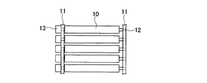
図10に家庭用のリアプロジェクタ100の一例を示す。この例では、メインスクリーン101とこれに画像を投影するプロジェクタ103を内蔵した筐体104の下部に巻き取り式、あるいは折り畳み式などの収納可能なサブスクリーン102が設けられている。このような構成を考えた場合、図10に破線Hで示した領域、すなわちメインスクリーン101からはみ出した領域にサブスクリーン用のプロジェクタ105を配置する構成は好ましくない。なぜならば、リアプロジェクタ用の置き台の選択肢が狭まったり、デザインや外観が劣って見られる傾向があったりするからである。勿論、リアプロジェクタ100が大型化するという問題もある。
FIG. 10 shows an example of a home
本発明は、上記の課題を解決するためになされたものであって、装置全体の小型化が図れるとともに、装置のメンテナンス性に優れたプロジェクタシステムおよびリアプロジェクタ、さらにはこれらに用いるスクリーンを提供することを目的とする。 The present invention has been made to solve the above-described problems, and provides a projector system and a rear projector that can reduce the size of the entire apparatus and that are excellent in maintainability of the apparatus, and a screen used for these. For the purpose.
上記の目的を達成するために、本発明のスクリーンは、複数のスクリーン部材を備え、前記複数のスクリーン部材が、投射された画像光の一部を散乱させることなく透過可能、かつ前記画像光の他の一部を散乱させつつ透過可能な第1のスクリーン部材と、散乱することなく前記第1のスクリーン部材を透過した前記画像光の一部を散乱させつつ反射可能な第2のスクリーン部材とを少なくとも含むことを特徴とする。
すなわち、本発明のスクリーンの最大の特徴点は、第1のスクリーン部材が、画像を生成する透過型スクリーンとしての機能と、光を透過させるだけの単なる透明部材としての機能の双方を併せ持つことである。
In order to achieve the above object, a screen according to the present invention includes a plurality of screen members, and the plurality of screen members can transmit without scattering a part of the projected image light, and the image light can be transmitted. A first screen member that can be transmitted while scattering the other part, and a second screen member that can reflect while scattering a part of the image light transmitted through the first screen member without scattering. It is characterized by including at least.
That is, the greatest feature of the screen of the present invention is that the first screen member has both a function as a transmissive screen for generating an image and a function as a mere transparent member that only transmits light. is there.
本発明のスクリーンによれば、画像光の一部を散乱させることなく透過可能、かつ画像光の他の一部を散乱させつつ透過可能な第1のスクリーン部材を備えているので、複数のプロジェクタを第1のスクリーン部材の背後に配置することができる。すなわち、第1のスクリーン部材上で画像光を散乱させつつ透過させ、画像を生成する第1のスクリーン部材用のプロジェクタを第1のスクリーン部材の背後に配置できるのは勿論のこと、第1のスクリーン部材は画像光の一部を散乱させることなく透過可能でもあるので、第2のスクリーン部材用のプロジェクタを第1のスクリーン部材の背後に配置することができる。このように、複数のプロジェクタを第1のスクリーン部材の背後に集中配置できるので、システム全体の小型化を図ることができ、メンテナンス作業もやりやすくなる。また、デザインや外観的にも優れたものとなる。 According to the screen of the present invention, since the first screen member that can transmit without scattering a part of the image light and can transmit the other part of the image light is provided, a plurality of projectors are provided. Can be placed behind the first screen member. That is, the projector for the first screen member that transmits the image light while scattering the image light on the first screen member and generates an image can be disposed behind the first screen member. Since the screen member can also transmit a part of the image light without being scattered, the projector for the second screen member can be disposed behind the first screen member. As described above, since a plurality of projectors can be centrally arranged behind the first screen member, the entire system can be reduced in size and maintenance work can be easily performed. In addition, the design and appearance are excellent.
また、本発明のスクリーンは、前記第1のスクリーン部材を実現する手段として、前記画像光の一部を散乱させることなく透過可能な状態と前記画像光の他の一部を散乱させつつ透過可能な状態とを時間的に切り替え可能とする構成を採用することができる。
この構成によれば、画像光を散乱させることなく透過させる状態と画像光を散乱させつつ透過させる状態とが時間的に独立して存在するので、2つのスクリーン部材のそれぞれに対して画像光を確実に振り分けることができる。
In addition, the screen of the present invention can be used as a means for realizing the first screen member so that it can transmit without scattering a part of the image light and can transmit while scattering another part of the image light. It is possible to adopt a configuration that allows switching between different states in terms of time.
According to this configuration, the state in which the image light is transmitted without being scattered and the state in which the image light is transmitted while being scattered are temporally independent, so that the image light is transmitted to each of the two screen members. Can be surely sorted.
本発明のスクリーンは、より具体的な一つの手段として、前記第1のスクリーン部材が、前記画像光の他の一部を散乱させつつ透過させるとともに、各々が回動可能とされた複数のスクリーン部材を備えた構成を採用することができる。
この構成によれば、任意の駆動手段を用いて上記複数のスクリーン部材を回動させることにより、複数のスクリーン部材が画像光の光路を遮る位置にある期間では、画像光を散乱させつつ透過させ、画像を生成する透過型スクリーンとして機能させることができる。一方、複数のスクリーン部材が画像光の光路を遮らない位置にある期間(逆に言えば、画像光の光路が複数のスクリーン部材間の隙間を抜ける位置にある期間)では、画像光を散乱させることなく透過させ、第2のスクリーン部材に対して画像光を透過させることができる。
The screen of the present invention is, as one more specific means, a plurality of screens in which the first screen member allows the other part of the image light to be scattered and transmitted, and each of the screens is rotatable. The structure provided with the member can be employed.
According to this configuration, by rotating the plurality of screen members using an arbitrary driving unit, the image light is scattered and transmitted during a period in which the plurality of screen members are in positions where they block the optical path of the image light. It can function as a transmissive screen for generating an image. On the other hand, in a period in which the plurality of screen members are in positions where they do not block the optical path of the image light (in other words, in a period in which the optical path of the image light passes through the gap between the plurality of screen members), the image light is scattered. And the image light can be transmitted to the second screen member.
本発明のスクリーンは、より具体的なもう一つの手段として、前記第1のスクリーン部材が、散乱状態と透明状態とを切り替え可能な高分子分散型液晶パネルからなるスクリーン部材を備えた構成を採用することができる。
この構成によれば、上の構成のようにスクリーン部材を機械的に移動させることなく、高分子分散型液晶パネルを電気的に駆動することにより、高分子分散液晶が散乱状態となる期間では、画像光を散乱させつつ透過させ、画像を生成する透過型スクリーンとして機能させることができる。一方、高分子分散液晶が透明状態となる期間では、画像光を散乱させることなく透過させ、第2のスクリーン部材に対して画像光を透過させることができる。
The screen of the present invention employs a configuration in which the first screen member includes a screen member made of a polymer-dispersed liquid crystal panel capable of switching between a scattering state and a transparent state as another more specific means. can do.
According to this configuration, the polymer-dispersed liquid crystal panel is electrically driven without mechanically moving the screen member as in the above configuration. The image light can be transmitted while being scattered to function as a transmission screen for generating an image. On the other hand, during the period in which the polymer-dispersed liquid crystal is in a transparent state, the image light can be transmitted without being scattered, and the image light can be transmitted to the second screen member.
あるいは、本発明のスクリーンは、前記第1のスクリーン部材を実現する手段として、前記第1のスクリーン部材が、前記画像光の一部を散乱させることなく透過可能な部位と前記画像光の他の一部を散乱させつつ透過可能な部位とを有している構成を採用することもできる。
上述した構成では、画像光を無散乱で透過させる状態と散乱させつつ透過させる状態とを時間的に切り替えているが、本構成は、第1のスクリーン部材が、無散乱で透過可能な部位と散乱させつつ透過可能な部位の2つの部位を空間的に兼ね備えた構成である。この構成によれば、スクリーンの作製時に第1のスクリーン部材をこの構成としておけば、使用時には第1のスクリーン部材を何ら駆動することなく、2つの機能を持たせることができる。
Alternatively, in the screen of the present invention, as a means for realizing the first screen member, the first screen member can transmit a part that does not scatter a part of the image light and other image light. It is also possible to adopt a configuration having a part that can be transmitted while being partially scattered.
In the above-described configuration, the state in which the image light is transmitted without scattering and the state in which the image light is transmitted while being scattered are temporally switched. It is the structure which has two site | parts of the site | part which can permeate | transmit while scattering. According to this configuration, if the first screen member has this configuration when the screen is manufactured, the first screen member can be given two functions without being driven at the time of use.
より具体的な構成として、前記画像光の一部を散乱させることなく透過可能な部位を、前記第1のスクリーン部材に設けられた孔で構成することができる。
この構成によれば、簡単な加工のみで、無散乱で透過可能な部位と散乱させつつ透過可能な部位とを容易に作り分けることができる。
As a more specific configuration, a portion that can be transmitted without scattering a part of the image light can be configured by a hole provided in the first screen member.
According to this configuration, it is possible to easily create a site that can be transmitted without scattering and a site that can be transmitted while being scattered only by simple processing.
あるいは、本発明のスクリーンは、前記第1のスクリーン部材を実現する手段として、前記第1のスクリーン部材が、前記画像光の一部を散乱させることなく透過可能でかつ前記画像光の他の一部を散乱させつつ透過可能な半透明スクリーン部材を備えた構成を採用することができる。
この構成は、上述したような第1のスクリーン部材が無散乱で透過可能な部位と散乱させつつ透過可能な部位の2つの部位に分かれている構成ではなく、第1のスクリーン部材全体が無散乱で透過可能な機能と散乱させつつ透過可能な機能を一様に併せ持っている構成である。この構成においては、適切な素材の半透明スクリーン部材を選択するだけでよく、半透明スクリーン部材に駆動手段を設けたり、加工を施したりすることなく、前記第1のスクリーン部材を実現することができる。
Alternatively, in the screen of the present invention, as a means for realizing the first screen member, the first screen member can be transmitted without scattering a part of the image light and the other one of the image light. The structure provided with the translucent screen member which can permeate | transmit while scattering a part can be employ | adopted.
This configuration is not a configuration in which the first screen member is divided into two parts, a part that can be transmitted without scattering and a part that can be transmitted while being scattered, but the entire first screen member is not scattered. It has a structure that has both a function that can be transmitted through and a function that can be transmitted while being scattered. In this configuration, it is only necessary to select a translucent screen member made of an appropriate material, and the first screen member can be realized without providing a driving means or processing the translucent screen member. it can.
本発明のプロジェクタシステムは、上記本発明のスクリーンが備えられるとともに、前記第1のスクリーン部材の視認側とは反対側に複数のプロジェクタが備えられ、前記複数のプロジェクタのうちの第1のプロジェクタからの画像光が前記第1のスクリーン部材に投射されるとともに、前記複数のプロジェクタのうちの第2のプロジェクタからの画像光が前記第1のスクリーン部材を介して前記第2のスクリーン部材に投射されることを特徴とする。なお、本明細書で言う「プロジェクタシステム」とは、プロジェクタとスクリーンとが別体で独立しており、組み合わせて使用するものを意味している。 The projector system of the present invention includes the screen of the present invention as described above, and a plurality of projectors on the side opposite to the viewing side of the first screen member, and the first projector among the plurality of projectors. Image light is projected onto the first screen member, and image light from a second projector of the plurality of projectors is projected onto the second screen member via the first screen member. It is characterized by that. The “projector system” referred to in this specification means that the projector and the screen are separate and independent and are used in combination.
本発明のプロジェクタシステムによれば、第1のプロジェクタ、第2のプロジェクタを含む複数のプロジェクタを第1のスクリーン部材の背後に集中配置できるので、システム全体の小型化を図ることができ、メンテナンス作業もやりやすくなる。また、デザインや外観的にも優れたものとなる。 According to the projector system of the present invention, since a plurality of projectors including the first projector and the second projector can be centrally arranged behind the first screen member, the entire system can be reduced in size and maintenance work can be achieved. Is also easier to do. In addition, the design and appearance are excellent.
また、前記第1のスクリーン部材として、前記画像光の一部を散乱させることなく透過可能な状態と前記画像光の他の一部を散乱させつつ透過可能な状態とが時間的に切り替え可能なものを採用した場合、前記切り替えが1秒間に60回以上行われることが望ましい。時間的な切り替えを行う場合は画像のちらつきが懸念されるが、この構成であれば、鑑賞者の目に画像のちらつきが感じにくくなる。 Further, as the first screen member, it is possible to switch temporally between a state in which a part of the image light can be transmitted without being scattered and a state in which the other part of the image light can be transmitted while being scattered. In the case of using a device, the switching is preferably performed 60 times or more per second. When performing temporal switching, there is a concern about image flickering, but with this configuration, it is difficult for the viewer to feel image flickering.
あるいは、前記第1のスクリーン部材が、前記画像光の一部を散乱させることなく透過可能な部位と前記画像光の他の一部を散乱させつつ透過可能な部位とを有する場合、前記第2のプロジェクタからの画像光が前記第1のスクリーン部材の前記散乱させることなく透過可能な部位のみに投射されるとともに、前記第1のプロジェクタからの画像光が前記第1のスクリーン部材の前記散乱させつつ透過可能な部位のみに投射されることが望ましい。
この構成によれば、第2のプロジェクタからの画像光が第1のスクリーン部材を介して第2のスクリーン部材に投射される構成であっても、第2のプロジェクタ側の画像が第1のスクリーン部材に映り込むことがなく、第1のプロジェクタ側の画像と第2のプロジェクタ側の画像とが確実に分離され、各スクリーン部材それぞれに鮮明な画像を生成することができる。
Alternatively, when the first screen member has a part that can be transmitted without scattering a part of the image light and a part that can be transmitted while scattering another part of the image light, the second The image light from the first projector is projected only on a portion of the first screen member that can be transmitted without being scattered, and the image light from the first projector is scattered by the first screen member. However, it is desirable to project only on the part which can permeate | transmit.
According to this configuration, even when the image light from the second projector is projected onto the second screen member via the first screen member, the image on the second projector side is the first screen. The image on the first projector side and the image on the second projector side are reliably separated without being reflected on the member, and a clear image can be generated on each screen member.
あるいは、前記第1のスクリーン部材が、前記画像光の一部を散乱させることなく透過可能でかつ前記画像光の他の一部を散乱させつつ透過可能な半透明スクリーン部材を備える場合、前記第2のプロジェクタからの画像光は、前記第1のプロジェクタからの画像光と同じ色あるいは近傍の色のみの光が選択されて前記第2のスクリーン部材に向けて投射されることが望ましい。
この構成では第1のスクリーン部材が機能の異なる2つの部位に分かれていないため、上述した構成とは逆に、第2のプロジェクタ側の画像が第1のスクリーン部材に映り込むことが避けられない。その場合でも、第2のプロジェクタからの画像光は第1のプロジェクタからの画像光と同じ色あるいは近傍の色のみの光が選択されているので、第1のスクリーン部材上に投射される第1のプロジェクタ側の画像が第2のプロジェクタ側の画像によって邪魔されることなく、各スクリーン部材に良好な画像を生成することができる。
Alternatively, when the first screen member includes a translucent screen member that is transmissive without scattering part of the image light and that is transmissive while scattering other part of the image light, It is desirable that the image light from the second projector is projected toward the second screen member by selecting light having the same color as the image light from the first projector or only in the vicinity thereof.
In this configuration, since the first screen member is not divided into two parts having different functions, it is inevitable that the image on the second projector side is reflected on the first screen member, contrary to the above-described configuration. . Even in such a case, as the image light from the second projector, light having only the same color as the image light from the first projector or a color in the vicinity thereof is selected. Therefore, the first light projected on the first screen member is used. A good image can be generated on each screen member without the image on the projector side being disturbed by the image on the second projector side.
本発明のリアプロジェクタは、上記本発明のスクリーンが筐体に備えられるとともに、前記筐体の内部に複数のプロジェクタが備えられ、前記複数のプロジェクタのうちの第1のプロジェクタからの画像光が前記第1のスクリーン部材に投射されるとともに、前記複数のプロジェクタのうちの第2のプロジェクタからの画像光が前記第1のスクリーン部材を介して前記第2のスクリーン部材に投射されることを特徴とする。なお、本明細書で言う「リアプロジェクタ」とは、上記「プロジェクタシステム」とは異なり、スクリーンと複数のプロジェクタとが一つの装置として一体となったものを意味している。 The rear projector of the present invention includes the above-described screen of the present invention in a casing and a plurality of projectors in the casing, and image light from a first projector among the plurality of projectors is Projected onto a first screen member, and image light from a second projector of the plurality of projectors is projected onto the second screen member via the first screen member. To do. Note that the “rear projector” referred to in the present specification is different from the “projector system” described above, and means that a screen and a plurality of projectors are integrated as one device.
本発明のリアプロジェクタによれば、第1のプロジェクタ、第2のプロジェクタを含む複数のプロジェクタを第1のスクリーン部材の背後に集中配置できるので、システム全体の小型化を図ることができ、メンテナンス作業もやりやすくなる。また、デザインや外観的にも優れたものとなる。 According to the rear projector of the present invention, since a plurality of projectors including the first projector and the second projector can be centrally arranged behind the first screen member, the entire system can be reduced in size and maintenance work can be achieved. Is also easier to do. In addition, the design and appearance are excellent.
本発明のリアプロジェクタにおいても、上記本発明のプロジェクタシステムと同様、前記第1のスクリーン部材が、前記画像光の一部を散乱させることなく透過可能な状態と前記画像光の他の一部を散乱させつつ透過可能な状態とが時間的に切り替え可能である場合、前記切り替えが1秒間に60回以上行われることが望ましい。
あるいは、前記第1のスクリーン部材が、前記画像光の一部を散乱させることなく透過可能な部位と前記画像光の他の一部を散乱させつつ透過可能な部位とを有する場合、前記第2のプロジェクタからの画像光が前記第1のスクリーン部材の前記散乱させることなく透過可能な部位のみに投射されるとともに、前記第1のプロジェクタからの画像光が前記第1のスクリーン部材の前記散乱させつつ透過可能な部位のみに投射されることが望ましい。
あるいは、前記第1のスクリーン部材が、前記画像光の一部を散乱させることなく透過可能でかつ前記画像光の他の一部を散乱させつつ透過可能な半透明スクリーン部材を備える場合、前記第2のプロジェクタからの画像光は、前記第1のプロジェクタからの画像光と同じ色あるいは近傍の色のみの光が選択されて前記第2のスクリーン部材に向けて投射されることが望ましい。
これらの構成を採用したときの作用、効果は、上述した本発明のプロジェクタシステムの場合と同様である。
Also in the rear projector of the present invention, as in the projector system of the present invention, the first screen member transmits a state in which a part of the image light can be transmitted without being scattered and the other part of the image light. In the case where it is possible to temporally switch between the state in which light can be transmitted while being scattered, it is preferable that the switching is performed 60 times or more per second.
Alternatively, when the first screen member has a part that can be transmitted without scattering a part of the image light and a part that can be transmitted while scattering another part of the image light, the second The image light from the first projector is projected only on a portion of the first screen member that can be transmitted without being scattered, and the image light from the first projector is scattered by the first screen member. However, it is desirable to project only on the part which can permeate | transmit.
Alternatively, when the first screen member includes a translucent screen member that is transmissive without scattering part of the image light and that is transmissive while scattering other part of the image light, It is desirable that the image light from the second projector is projected toward the second screen member by selecting light having the same color as the image light from the first projector or only in the vicinity thereof.
Operations and effects when these configurations are employed are the same as those of the projector system of the present invention described above.
[第1の実施の形態]
以下、本発明の第1の実施の形態を図1〜図3を参照して説明する。
図1は本実施形態のプロジェクタシステムの概略構成を示す斜視図、図2は第1のスクリーン部材の要部を示す正面図、図3(a)、(b)は第1のスクリーン部材の動作を説明するための側面図である。なお、以下の全ての図面においては、各構成要素を見やすくするため、各部材の縮尺や寸法の比率等は適宜異ならせている。
[First Embodiment]
A first embodiment of the present invention will be described below with reference to FIGS.
1 is a perspective view illustrating a schematic configuration of a projector system according to the present embodiment, FIG. 2 is a front view illustrating a main part of a first screen member, and FIGS. 3A and 3B are operations of the first screen member. It is a side view for demonstrating. In all the drawings below, the scales and dimensional ratios of the members are appropriately changed in order to make each component easy to see.
本実施形態のプロジェクタシステム1は、図1に示すように、第1のスクリーン部材2、第2のスクリーン部材3を有する2面式のスクリーン4と、第1のプロジェクタ5、第2のプロジェクタ6の2台のプロジェクタ7とから概略構成されている。この例では、第1のスクリーン部材2と第2のスクリーン部材3とは略直角をなすように配置され、第1のスクリーン部材2が鉛直方向、第2のスクリーン部材3が水平方向に配置されている。
As shown in FIG. 1, the
第1のプロジェクタ5は第1のスクリーン部材2に対して画像光を投射するもの、第2のプロジェクタ6は第2のスクリーン部材3に対して画像光を投射するものである。これら2台のプロジェクタ7はともに第1のスクリーン部材2の背面側に設置されている。各プロジェクタ5,6の画像光の射出口には、画像光の投射方向を変えるためのアダプタ8が取り付けられている。アダプタ8の作用により、第1のプロジェクタ5からの画像光は第1のスクリーン部材2に向けて略水平方向に射出され、第2のプロジェクタ6からの画像光は第2のスクリーン部材3に向けて斜め下方に向けて射出される。勿論アダプタを使わずとも、目的のスクリーンに画像が映し出せるのであれば、プロジェクタ自身を傾けたり、リアプロジェクタのように一旦鏡で反射させたりしてもよい。このようなプロジェクタシステム1において、鑑賞者は、第1のスクリーン部材2を挟んでプロジェクタ7と反対側から画像を鑑賞する。
The
第1のスクリーン部材2は、各々が回動可能とされた複数のスクリーン部材10を備えている。各スクリーン部材10は、画像光を散乱させつつ透過可能な板材、いわゆる一般的な透過型スクリーンを構成する板材から構成されている。第1のスクリーン部材2においては、図2に示すように、鉛直方向に延在する枠体11に対して水平方向に延在する回動軸12が設置されており、この回動軸12を中心として各スクリーン部材10がモータ13の動作により鉛直面内で回動する構成となっている。各スクリーン部材10は、360°回転する動作を連続的に繰り返す構成でも良いし、鉛直方向に立った状態と鉛直方向から所定の角度だけ傾いた状態(後述する図3(a)と図3(b))との間を往復するように回動する構成でも良い。各スクリーン部材10の動作は、既存の同期モータやモータ制御用のコントローラなどで同期させる必要がある。
The
本実施形態では、第1のスクリーン部材2は、画像光を散乱させることなく透過可能な状態と画像光を散乱させつつ透過可能な状態とが時間的に切り替わる構成となっている。また、プロジェクタ7側も、第1のプロジェクタ5と第2のプロジェクタ6とが画像光を間欠的に交互に射出する。図3(a)に示すように、各スクリーン部材10が鉛直方向に立った期間では第1のプロジェクタ5からの画像光が第1のスクリーン部材2に向けて射出される。このとき、第1のスクリーン部材2の全体が画像光を散乱させつつ透過可能な状態となり、透過型スクリーンとして機能する第1のスクリーン部材2上に第1のプロジェクタ5からの画像が投影される。
In the present embodiment, the
一方、図3(b)に示すように、各スクリーン部材10が斜めに傾いた期間では第2のプロジェクタ6からの画像光が射出される。このとき、各スクリーン部材10間の隙間を第2のプロジェクタ6からの画像光が通過するように各スクリーン部材10の角度とアダプタ8の角度が設定されているため、第2のプロジェクタ6からの画像光は第1のスクリーン部材2で何ら散乱されることなく透過し、反射型スクリーンとして機能する第2のスクリーン部材3に第2のプロジェクタ6からの画像が投影される。各スクリーン部材10への画像光の投射は、少なくとも60回以上行われることが望ましい。その理由は、鑑賞者の目に画像のちらつきが感じにくくなるためである。
On the other hand, as shown in FIG. 3B, image light from the
本実施形態のプロジェクタシステム1によれば、2台のプロジェクタ7を第1のスクリーン部材2の背後に集中配置できるので、システム全体の小型化を図ることができ、メンテナンス作業も容易になる。また、デザインや外観的にも優れたものとなる。
According to the
なお、本実施形態では、第1のスクリーン部材2が水平方向に延在する回動軸12を有し、この回動軸12を中心として各スクリーン部材10が鉛直面内で回動する構成としたが、この構成に代えて、第1のスクリーン部材が鉛直方向に延在する回動軸を有し、この回動軸を中心として各スクリーン部材が水平面内で回動する構成としても良い。さらに、図3(b)において各スクリーン部材10を傾ける角度は、第1のスクリーン部材2の上部と下部で一定でも良いし、画像光の射出角度の違いに応じて第1のスクリーン部材2の上部と下部で変えても良い。
In the present embodiment, the
また、第1のスクリーン部材2の背後に2台のプロジェクタ7、すなわち各スクリーン部材2,3に対して1台ずつのプロジェクタ5,6を配置したが、各スクリーン部材2,3に対して2台以上のプロジェクタを配置しても良い。こうすることで、立体画像表示や高画質化のためのタイリングを実現することができる。勿論、マイクロポールなどの立体画像表示方式などを用いて1台のプロジェクタで立体視を可能にしても良い。
Further, two projectors 7, that is, one
[第2の実施の形態]
以下、本発明の第2の実施の形態を図4を参照して説明する。
図4は本実施形態のプロジェクタシステムの概略構成を示す斜視図である。本実施形態のプロジェクタシステムの基本構成は第1実施形態と同様であり、第1のスクリーン部材の構成が異なるのみである。よって、以下では第1のスクリーン部材の構成についてのみ説明し、共通な個所の説明は省略する。また、図4において図1と共通の構成要素には同一の符号を付す。
[Second Embodiment]
The second embodiment of the present invention will be described below with reference to FIG.
FIG. 4 is a perspective view showing a schematic configuration of the projector system of the present embodiment. The basic configuration of the projector system of this embodiment is the same as that of the first embodiment, and only the configuration of the first screen member is different. Therefore, only the configuration of the first screen member will be described below, and description of common parts will be omitted. In FIG. 4, the same reference numerals are given to the same components as those in FIG.
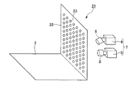
本実施形態のプロジェクタシステム21においては、図4に示すように、第1のスクリーン部材22が、画像光の一部を散乱させることなく透過可能な部位と画像光の他の一部を散乱させつつ透過可能な部位とを有している。具体的には、第1のスクリーン部材22が、多数の円形の孔23が形成されたスクリーン部材から構成されている。スクリーン部材自体は、画像光を散乱させつつ透過可能な板材、いわゆる一般的な透過型スクリーンを構成する板材から構成されている。なお、孔23の形状は細長いスリット状でも良いし、例えば第1実施形態のスクリーン部材を図3(b)に示す状態で固定したものでも良く、第2のプロジェクタ6からの画像光が透過できる形状や寸法であれば特に限定されない。
In the
2台のプロジェクタ7の配置は第1実施形態と同様であり、第1のプロジェクタ5からの画像光が第1のスクリーン部材22に向けて射出される。このとき、透過型スクリーンとして機能する第1のスクリーン部材22上に第1のプロジェクタ5の画像が投影される。一方、第2のプロジェクタ6からの画像光が第1のスクリーン部材22の孔23を通過するようになっており、第2のプロジェクタ6からの画像光は第1のスクリーン部材22で散乱されることなく透過し、第2のスクリーン部材3に第2のプロジェクタ6からの画像が投影される。
The arrangement of the two projectors 7 is the same as in the first embodiment, and image light from the
本実施形態の場合、第1実施形態と異なり、第1のスクリーン部材22は画像光を無散乱で透過可能な部位と散乱させつつ透過可能な部位とが空間的に決まっているため、各プロジェクタ5,6からの画像は、孔23の形状、配置等を考慮して決定することが望ましい。例えば、第1のスクリーン部材22では孔23を除いた部分が表示領域となるため、第1のプロジェクタ5からの画像光は孔23を除いた部分で画像が構成されるようにし、孔23の部分を透過する光は第2のスクリーン部材3上の画像に支障がない画像を構成することが望ましい。一方、第2のプロジェクタ6からの画像光は孔23を透過した部分で画像が構成されるようにし、孔23以外の部分にあたる光は第1のスクリーン部材22上の画像に支障がない画像を構成することが望ましい。
In the case of the present embodiment, unlike the first embodiment, the
本実施形態においても、システム全体の小型化が図れるとともに、メンテナンス作業が容易になる、といった第1実施形態と同様の効果を得ることができる。また、第1実施形態のようにスクリーンの駆動手段を備える必要がなく、一般の透過型スクリーンに孔23を形成するという簡単な加工のみで、無散乱で透過可能な部位と散乱させつつ透過可能な部位とを容易に作り分けることができる。
In this embodiment, the same effect as that of the first embodiment can be obtained in that the entire system can be reduced in size and the maintenance work is facilitated. Further, unlike the first embodiment, it is not necessary to provide a screen driving means, and it is possible to transmit light while being scattered with a non-scattering transmissive portion only by a simple process of forming a
[第3の実施の形態]
以下、本発明の第3の実施の形態を図5を参照して説明する。
図5は本実施形態のプロジェクタシステムの概略構成を示す斜視図である。本実施形態のプロジェクタシステムの基本構成は第1実施形態と同様であり、第1のスクリーン部材の構成が異なるのみである。よって、以下では第1のスクリーン部材の構成についてのみ説明し、共通な個所の説明は省略する。また、図5において図1と共通の構成要素には同一の符号を付す。
[Third Embodiment]
The third embodiment of the present invention will be described below with reference to FIG.
FIG. 5 is a perspective view showing a schematic configuration of the projector system of the present embodiment. The basic configuration of the projector system of this embodiment is the same as that of the first embodiment, and only the configuration of the first screen member is different. Therefore, only the configuration of the first screen member will be described below, and description of common parts will be omitted. In FIG. 5, the same reference numerals are given to the same components as those in FIG. 1.
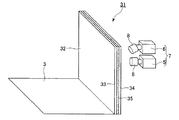
本実施形態のプロジェクタシステム31においては、図5に示すように、第1のスクリーン部材32が、散乱状態と透明状態とを切り替え可能な高分子分散型液晶パネルから構成されている。具体的には、2枚の透明基板33,34間に高分子分散液晶35が挟持されており、各透明基板33,34の高分子分散液晶35側の面にはベタ状の透明電極(図示せず)が形成されている。したがって、電圧印加状態、無印加状態を時間的に交互に切り替えることによって高分子分散液晶35を散乱状態とするか透明状態とするかを切り替える。
In the
2台のプロジェクタ7の配置は第1実施形態と同様であり、第1のプロジェクタ5と第2のプロジェクタ6とが画像光を間欠的に交互に射出する点も同様である。第1のスクリーン部材32が散乱状態となった期間では第1のプロジェクタ5からの画像光が第1のスクリーン部材32に向けて射出される。このとき、第1のスクリーン部材32の全体が画像光を散乱させつつ透過可能な状態となり、透過型スクリーンとして機能する第1のスクリーン部材32上に第1のプロジェクタ5の画像が投影される。
The arrangement of the two projectors 7 is the same as in the first embodiment, and the same is true in that the
一方、第1のスクリーン部材32が透明状態となった期間では第2のプロジェクタ6からの画像光が射出される。このとき、第2のプロジェクタ6からの画像光は第1のスクリーン部材32で散乱されることなく透過し、反射型スクリーンとして機能する第2のスクリーン部材3に第2のプロジェクタ6の画像が投影される。各スクリーン部材32,3への画像光の投射は、少なくとも60回以上行われることが望ましい。その理由は、鑑賞者の目に画像のちらつきが感じにくくなるためである。
On the other hand, the image light from the
本実施形態においても、システム全体の小型化が図れるとともに、メンテナンス作業が容易になる、といった第1実施形態と同様の効果を得ることができる。また、第1実施形態のようにスクリーンを移動させる手段を備える必要がないため、騒音、振動等の少ないシステムを構成することができる。 In this embodiment, the same effect as that of the first embodiment can be obtained in that the entire system can be reduced in size and the maintenance work is facilitated. Further, since there is no need to provide a means for moving the screen as in the first embodiment, a system with less noise, vibration, etc. can be configured.
[第4の実施の形態]
以下、本発明の第4の実施の形態を図6〜9を参照して説明する。
図6は本実施形態のプロジェクタシステムの概略構成を示す斜視図である。本実施形態のプロジェクタシステムの基本構成は第1実施形態と同様であり、第1のスクリーン部材の構成が異なる。また、第1〜第3実施形態では第2のプロジェクタからの画像が第1のスクリーン部材に映り込まないことが前提であったが、本実施形態は第2のプロジェクタからの画像が第1のスクリーン部材に映り込むことを想定した構成である。図7〜図9はその際の動作を説明するための図である。また、図6において図1と共通の構成要素には同一の符号を付す。
[Fourth Embodiment]
Hereinafter, a fourth embodiment of the present invention will be described with reference to FIGS.
FIG. 6 is a perspective view showing a schematic configuration of the projector system of the present embodiment. The basic configuration of the projector system of this embodiment is the same as that of the first embodiment, but the configuration of the first screen member is different. In the first to third embodiments, it is assumed that the image from the second projector is not reflected on the first screen member. However, in this embodiment, the image from the second projector is the first image. It is the structure assumed to be reflected on the screen member. 7 to 9 are diagrams for explaining the operation at that time. In FIG. 6, the same reference numerals are given to the same components as those in FIG. 1.
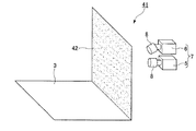
本実施形態のプロジェクタシステム41においては、図6に示すように、第1のスクリーン部材42が、画像光の一部を散乱させることなく透過可能でかつ散乱させつつ透過可能な磨りガラス等の半透明スクリーン部材から構成されている。すなわち、本実施形態の構成は、上述した実施形態のような第1のスクリーン部材が無散乱で透過可能な部位と散乱させつつ透過可能な部位の2つの部位に分かれている構成ではなく、第1のスクリーン部材42の全体が無散乱で透過可能な機能と散乱させつつ透過可能な機能を一様に併せ持っている構成である。
In the
第1〜第3実施形態のように、第2のプロジェクタ6側の画像が第1のスクリーン部材に映り込まない構成の場合には、第1のプロジェクタ5側の画像と第2のプロジェクタ6側の画像が確実に分離され、各スクリーン部材それぞれに鮮明な画像を生成することができる。一方、本実施形態の場合には、第1のスクリーン部材42が機能の異なる2つの部位に分かれていないため、上述した構成とは逆に、第2のプロジェクタ6側の画像が第1のスクリーン部材42に映り込むことが避けられない。そこで、第1のプロジェクタ5が正面の第1のスクリーン部材42に画像光を投射する一方、第2のプロジェクタ6は第1のプロジェクタから5の画像光と同じ色あるいは近傍の色のみの光を選択的に第2のスクリーン部材3に向けて投射する。
In the case where the image on the
図7は、オリジナル画像から各スクリーン部材に映し出す画像を生成する方法を示すフローチャートである。本実施形態では第1のスクリーン部材42に映し出される画像がメインの画像であり、第2のスクリーン部材3に映し出される画像は補助的なものであると考え、第1のスクリーン部材42をメインスクリーン、第2のスクリーン部材3をサブスクリーンと呼ぶこともある。まず最初に、第2のスクリーン部材3上の任意の座標の色が、第1のスクリーン部材42を通過する際の座標の色と同じかどうかを調べる(ステップS10)。
FIG. 7 is a flowchart illustrating a method for generating an image to be displayed on each screen member from an original image. In the present embodiment, the image displayed on the
第2のスクリーン部材3(サブスクリーン)の任意の座標が第1のスクリーン部材42(メインスクリーン)を通過する際にどの座標に対応するかという各スクリーン部材間の座標の対応関係は、図8のような対応表としてプロジェクタシステム41の制御部が保有している。この対応関係は、事前に射影変換アルゴリズム等を手掛かりに求めても良いし、実際に計測しても良い。なお、座標の単位は画素の位置とすることが望ましい。そして、第2のスクリーン部材3上の座標の色と第1のスクリーン部材42を通過する際の座標の色を比較し、同じ色(例えば青と青)もしくは近傍の色(例えば青とシアン)の場合、図8中の「一致状態」の欄を「有効」とする。
The correspondence relationship between the coordinates of each screen member, which coordinate corresponds to the arbitrary coordinate of the second screen member 3 (sub-screen) when passing through the first screen member 42 (main screen), is shown in FIG. The control unit of the
なお、本実施形態ではサブスクリーンは1つのみであるが、2つ以上のサブスクリーンを有する場合には、図9に示すように、メインスクリーン座標をいくつのサブスクリーンへの画像光が通過するのかを記録する。図9の表示回数の初期値は「1」であり、1回通過すると判るたびに表示回数を「1」だけ増加させる。それ以外は表示回数を変化させない。このような処理を各座標に対して行う。 In the present embodiment, there is only one sub-screen. However, when there are two or more sub-screens, as shown in FIG. 9, the image light to several sub-screens passes through the main screen coordinates. To record. The initial value of the number of times of display in FIG. 9 is “1”, and the number of times of display is increased by “1” every time it is determined that the number of times of passage is one. Otherwise, the display count is not changed. Such processing is performed for each coordinate.
次に、第1のスクリーン部材42(メインスクリーン)と第2のスクリーン部材3(サブスクリーン)で映し出すための画像を生成する(ステップS20)。サブスクリーンに映し出す画像の各画素に対して、図8の一致状態を見ながら表示できるかどうかを調べる。表示できる場合とは「有効」の場合であり、図9に基づいてメインスクリーンを通過する回数(表示回数)に合わせて色の明るさを落とす。一方、表示できない場合(「無効」の場合)には画素の色を白またはメインスクリーンと同等の色に設定する。このような処理を全ての画素に対して行う。また、メインスクリーンに対しても色を変更する画素がある。それは図9において表示回数が2以上の場合である。その画素位置では表示回数に応じて色の明るさを落とす。このようにして、メインスクリーン、サブスクリーンに投影する画像が生成される。本構成の場合、芸術的な幾何学模様などの単純な絵柄を投影するのが最適である。 Next, an image to be projected on the first screen member 42 (main screen) and the second screen member 3 (subscreen) is generated (step S20). Whether or not each pixel of the image displayed on the sub-screen can be displayed while checking the matching state of FIG. 8 is examined. The case where it can be displayed is a case where it is “valid”, and the brightness of the color is reduced according to the number of times of passing through the main screen (number of times of display) based on FIG. On the other hand, when display is not possible (in the case of “invalid”), the pixel color is set to white or a color equivalent to the main screen. Such processing is performed for all pixels. There are also pixels that change the color of the main screen. This is the case where the number of display times is 2 or more in FIG. At that pixel position, the brightness of the color is reduced according to the number of display times. In this way, an image to be projected on the main screen and the sub screen is generated. In the case of this configuration, it is best to project a simple pattern such as an artistic geometric pattern.
本実施形態においても、システム全体の小型化が図れるとともに、メンテナンス作業が容易になる、といった第1実施形態と同様の効果を得ることができる。また、適切な素材の半透明スクリーン部材を選択するだけでよく、半透明スクリーン部材に駆動手段を設けたり、加工を施したりすることなく、第1のスクリーン部材42を実現することができる。さらに、第2のプロジェクタ6からの画像光として第1のプロジェクタ5からの画像光と同じ色あるいは近傍の色のみの光が選択されているので、第1のスクリーン部材42上に投射される第1のプロジェクタ5側の画像が第2のプロジェクタ6側の画像によって邪魔されることなく、各スクリーン部材42,3に良好な画像を生成することができる。
In this embodiment, the same effect as that of the first embodiment can be obtained in that the entire system can be reduced in size and the maintenance work is facilitated. Moreover, it is only necessary to select a translucent screen member made of an appropriate material, and the
なお、本発明の技術範囲は上記実施の形態に限定されるものではなく、本発明の趣旨を逸脱しない範囲において種々の変更を加えることが可能である。例えば上記実施形態ではプロジェクタとスクリーンとが別体で独立しており、組み合わせて使用する「プロジェクタシステム」の例を挙げたが、スクリーンと複数のプロジェクタとが筐体内に収納され、一つの装置として一体となった「リアプロジェクタ」に本発明を適用することも可能である。さらに、上記実施形態では2面式のスクリーンの例を挙げたが、3面以上のスクリーンを備えても良く、複数のスクリーンの設置方向も上記実施形態の鉛直方向、水平方向(2面の場合)の他、鑑賞者の正面方向および側面方向に設置するなどしても良い。 The technical scope of the present invention is not limited to the above embodiment, and various modifications can be made without departing from the spirit of the present invention. For example, in the above embodiment, the projector and the screen are separate and independent, and an example of a “projector system” used in combination is given. However, the screen and a plurality of projectors are housed in a housing and are used as one device. It is also possible to apply the present invention to an integrated “rear projector”. Furthermore, in the above embodiment, an example of a two-sided screen has been described. However, three or more screens may be provided, and a plurality of screens may be installed in the vertical direction and the horizontal direction (in the case of two sides). In addition, it may be installed in the front and side directions of the viewer.
1,21,31,41…プロジェクタシステム、2,22,32,42…第1のスクリーン部材、3…第2のスクリーン部材、4…スクリーン、5…第1のプロジェクタ、6…第2のプロジェクタ、10…スクリーン部材、23…孔。
1, 2, 31, 32 ... projector system, 2, 22, 32, 42 ... first screen member, 3 ... second screen member, 4 ... screen, 5 ... first projector, 6 ... second projector 10: Screen member, 23: Hole.
Claims (15)
前記複数のプロジェクタのうちの第1のプロジェクタからの画像光が前記第1のスクリーン部材に投射されるとともに、前記複数のプロジェクタのうちの第2のプロジェクタからの画像光が前記第1のスクリーン部材を介して前記第2のスクリーン部材に投射されることを特徴とするプロジェクタシステム。 A screen according to any one of claims 1 to 7 is provided, and a plurality of projectors are provided on the side opposite to the viewing side of the first screen member,
Image light from a first projector of the plurality of projectors is projected onto the first screen member, and image light from a second projector of the plurality of projectors is projected to the first screen member. Projecting to the second screen member via a projector.
前記第2のプロジェクタからの画像光が前記第1のスクリーン部材の前記散乱させることなく透過可能な部位のみに投射されるとともに、前記第1のプロジェクタからの画像光が前記第1のスクリーン部材の前記散乱させつつ透過可能な部位のみに投射されることを特徴とする請求項8に記載のプロジェクタシステム。 The first screen member has a part that can be transmitted without scattering a part of the image light and a part that can be transmitted while scattering another part of the image light,
The image light from the second projector is projected only on the part of the first screen member that can be transmitted without being scattered, and the image light from the first projector is projected on the first screen member. The projector system according to claim 8, wherein the projector system is projected only on the part that can be transmitted while being scattered.
前記第2のプロジェクタからの画像光は、前記第1のプロジェクタからの画像光と同じ色あるいは近傍の色のみの光が選択されて前記第2のスクリーン部材に向けて投射されることを特徴とする請求項8に記載のプロジェクタシステム。 The first screen member includes a translucent screen member that is transmissive without scattering part of the image light and transmissive while scattering other part of the image light,
The image light from the second projector is projected toward the second screen member by selecting light of the same color as the image light from the first projector or only in the vicinity thereof. The projector system according to claim 8.
前記複数のプロジェクタのうちの第1のプロジェクタからの画像光が前記第1のスクリーン部材に投射されるとともに、前記複数のプロジェクタのうちの第2のプロジェクタからの画像光が前記第1のスクリーン部材を介して前記第2のスクリーン部材に投射されることを特徴とするリアプロジェクタ。 A screen according to any one of claims 1 to 7 is provided in a housing, and a plurality of projectors are provided in the housing.
Image light from a first projector of the plurality of projectors is projected onto the first screen member, and image light from a second projector of the plurality of projectors is projected to the first screen member. The rear projector is projected onto the second screen member via a projector.
前記第2のプロジェクタからの画像光が前記第1のスクリーン部材の前記散乱させることなく透過可能な部位のみに投射されるとともに、前記第1のプロジェクタからの画像光が前記第1のスクリーン部材の前記散乱させつつ透過可能な部位のみに投射されることを特徴とする請求項12に記載のリアプロジェクタ。 The first screen member has a part that can be transmitted without scattering a part of the image light and a part that can be transmitted while scattering another part of the image light,
The image light from the second projector is projected only on the part of the first screen member that can be transmitted without being scattered, and the image light from the first projector is projected on the first screen member. The rear projector according to claim 12, wherein the rear projector is projected only on a part that can be transmitted while being scattered.
前記第2のプロジェクタからの画像光は、前記第1のプロジェクタからの画像光と同じ色あるいは近傍の色のみの光が選択されて前記第2のスクリーン部材に向けて投射されることを特徴とする請求項12に記載のリアプロジェクタ。
The first screen member includes a translucent screen member that is transmissive without scattering part of the image light and transmissive while scattering other part of the image light,
The image light from the second projector is projected toward the second screen member by selecting light of the same color as the image light from the first projector or only in the vicinity thereof. The rear projector according to claim 12.
Priority Applications (1)
| Application Number | Priority Date | Filing Date | Title |
|---|---|---|---|
| JP2005198497A JP2007017664A (en) | 2005-07-07 | 2005-07-07 | Screen, projector system, rear projector |
Applications Claiming Priority (1)
| Application Number | Priority Date | Filing Date | Title |
|---|---|---|---|
| JP2005198497A JP2007017664A (en) | 2005-07-07 | 2005-07-07 | Screen, projector system, rear projector |
Publications (1)
| Publication Number | Publication Date |
|---|---|
| JP2007017664A true JP2007017664A (en) | 2007-01-25 |
Family
ID=37754896
Family Applications (1)
| Application Number | Title | Priority Date | Filing Date |
|---|---|---|---|
| JP2005198497A Withdrawn JP2007017664A (en) | 2005-07-07 | 2005-07-07 | Screen, projector system, rear projector |
Country Status (1)
| Country | Link |
|---|---|
| JP (1) | JP2007017664A (en) |
Cited By (4)
| Publication number | Priority date | Publication date | Assignee | Title |
|---|---|---|---|---|
| JP2007025355A (en) * | 2005-07-19 | 2007-02-01 | Matsushita Electric Works Ltd | Illumination apparatus for space production |
| JP2010160216A (en) * | 2009-01-06 | 2010-07-22 | Teijin Ltd | Video display system |
| JP2011525635A (en) * | 2008-05-02 | 2011-09-22 | マイクロソフト コーポレーション | Projecting an image onto a tangible user interface |
| WO2016067572A1 (en) * | 2014-10-31 | 2016-05-06 | Sharp Kabushiki Kaisha | Transparent display including a screen with patterned light deflective elements |
-
2005
- 2005-07-07 JP JP2005198497A patent/JP2007017664A/en not_active Withdrawn
Cited By (5)
| Publication number | Priority date | Publication date | Assignee | Title |
|---|---|---|---|---|
| JP2007025355A (en) * | 2005-07-19 | 2007-02-01 | Matsushita Electric Works Ltd | Illumination apparatus for space production |
| JP2011525635A (en) * | 2008-05-02 | 2011-09-22 | マイクロソフト コーポレーション | Projecting an image onto a tangible user interface |
| US8272743B2 (en) | 2008-05-02 | 2012-09-25 | Microsoft Corporation | Projection of images onto tangible user interfaces |
| JP2010160216A (en) * | 2009-01-06 | 2010-07-22 | Teijin Ltd | Video display system |
| WO2016067572A1 (en) * | 2014-10-31 | 2016-05-06 | Sharp Kabushiki Kaisha | Transparent display including a screen with patterned light deflective elements |
Similar Documents
| Publication | Publication Date | Title |
|---|---|---|
| US9179134B2 (en) | Multi-layer plenoptic displays that combine multiple emissive and light modulating planes | |
| US9661316B2 (en) | Multi-layer image display device | |
| US9791706B2 (en) | Mutli-layer plenoptic displays that combine multiple emissive and light modulating planes | |
| CN1902946A (en) | A laser projection display | |
| JP4462303B2 (en) | Image display device | |
| JP2005164916A (en) | Stereoscopic display device | |
| EP2535762A2 (en) | Multi-layer image display device | |
| AU2005332290A1 (en) | Method and apparatus for generating 3D images | |
| JP2015127799A (en) | Display device and display device frame | |
| US9749611B2 (en) | Stereoscopic image device | |
| CN112596263B (en) | Space stereo imaging device and method | |
| JP3605572B2 (en) | Three-dimensional image display device, point light emitting member and point light transmitting member | |
| JP3569522B2 (en) | Display device | |
| JP2009098326A (en) | Three-dimensional image forming apparatus | |
| JP2007017664A (en) | Screen, projector system, rear projector | |
| JP2015031837A (en) | Stereoscopic image display device | |
| JP2010020037A (en) | Three-dimensional image display method and three-dimensional image display device | |
| JP4605507B2 (en) | Three-dimensional stereoscopic image display device | |
| EP1683367B1 (en) | Multi-plane display for displaying overlapping images | |
| JP4291021B2 (en) | Image display device | |
| JP3523605B2 (en) | 3D video display | |
| JP4826700B2 (en) | 3D display device | |
| JPH09222584A (en) | Stereoscopic video display device | |
| KR20080034303A (en) | Dual view display device and backlight unit thereof | |
| WO2023181598A1 (en) | Display device, display method, and program |
Legal Events
| Date | Code | Title | Description |
|---|---|---|---|
| A300 | Withdrawal of application because of no request for examination |
Free format text: JAPANESE INTERMEDIATE CODE: A300 Effective date: 20081007 |