JP2007014875A - Method for deodorizing polymerization furnace - Google Patents
Method for deodorizing polymerization furnace Download PDFInfo
- Publication number
- JP2007014875A JP2007014875A JP2005198391A JP2005198391A JP2007014875A JP 2007014875 A JP2007014875 A JP 2007014875A JP 2005198391 A JP2005198391 A JP 2005198391A JP 2005198391 A JP2005198391 A JP 2005198391A JP 2007014875 A JP2007014875 A JP 2007014875A
- Authority
- JP
- Japan
- Prior art keywords
- exhaust
- odor
- polymerization
- pattern
- raw material
- Prior art date
- Legal status (The legal status is an assumption and is not a legal conclusion. Google has not performed a legal analysis and makes no representation as to the accuracy of the status listed.)
- Withdrawn
Links
Images


Classifications
-
- Y—GENERAL TAGGING OF NEW TECHNOLOGICAL DEVELOPMENTS; GENERAL TAGGING OF CROSS-SECTIONAL TECHNOLOGIES SPANNING OVER SEVERAL SECTIONS OF THE IPC; TECHNICAL SUBJECTS COVERED BY FORMER USPC CROSS-REFERENCE ART COLLECTIONS [XRACs] AND DIGESTS
- Y02—TECHNOLOGIES OR APPLICATIONS FOR MITIGATION OR ADAPTATION AGAINST CLIMATE CHANGE
- Y02P—CLIMATE CHANGE MITIGATION TECHNOLOGIES IN THE PRODUCTION OR PROCESSING OF GOODS
- Y02P20/00—Technologies relating to chemical industry
- Y02P20/10—Process efficiency
Abstract
Description
本発明は、原料組成物を熱重合する重合炉の脱臭方法に関する。 The present invention relates to a deodorizing method for a polymerization furnace in which a raw material composition is thermally polymerized.
眼鏡レンズ等のプラスチックレンズの製造は、注型成形法、射出成形法、切削研磨法等により、所望の光学性能を有する形状が形成される。このうち、高性能のプラスチックレンズの製造には、注型成形法が広く用いられている。注型成形法は、所望の成形面を有する2枚のガラス型を所定の間隔に対向配置し、その周面を粘着テープ等で封止したモールド型の内部に、原料組成物を注入した後、原料組成物を加熱して硬化(熱重合)させ、プラスチックレンズを得ることができる。 In manufacturing a plastic lens such as an eyeglass lens, a shape having a desired optical performance is formed by a cast molding method, an injection molding method, a cutting polishing method, or the like. Of these, the casting method is widely used for the production of high-performance plastic lenses. The casting molding method is a method in which two glass molds having a desired molding surface are arranged opposite to each other at a predetermined interval, and a raw material composition is injected into a mold die whose peripheral surface is sealed with an adhesive tape or the like. The raw material composition can be heated and cured (thermal polymerization) to obtain a plastic lens.
こうした原料組成物の熱重合には、一般的に温度制御装置として重合炉が用いられる。熱重合は、原料組成物が注入されたモールド型が重合炉内に載置され、重合炉が所定の温度パターン(後述する図1参照)に温度制御されて、原料組成物の硬化が行われる。この熱重合の際、モールド型(原料組成物)は、20時間程度の経過時間内に30〜120℃程度に温度制御(加熱)され、重合される原料組成物から炭化水素化合物等の臭気が発生する。この発生した臭気を、重合炉内から効率良く排気および脱臭することが求められる。 For the thermal polymerization of such raw material compositions, a polymerization furnace is generally used as a temperature control device. In the thermal polymerization, the mold die into which the raw material composition is injected is placed in a polymerization furnace, the temperature of the polymerization furnace is controlled to a predetermined temperature pattern (see FIG. 1 described later), and the raw material composition is cured. . During this thermal polymerization, the mold (raw material composition) is temperature-controlled (heated) to about 30 to 120 ° C. within an elapsed time of about 20 hours, and odors such as hydrocarbon compounds are produced from the raw material composition to be polymerized. appear. It is required to efficiently exhaust and deodorize the generated odor from the inside of the polymerization furnace.
重合炉とは異なるが、工場より発生する塵埃を、ガス温度、ダスト濃度等の条件から自動的に運転パターンを選択し、インバータ等の回転数制御装置で吸引ファンの回転数を制御し、省エネルギー運転を行う集塵装置の管理システムが提案されている(例えば、特許文献1参照)。 Although different from the polymerization furnace, the operation pattern of dust generated from the factory is automatically selected based on conditions such as gas temperature and dust concentration, and the rotation speed of the suction fan is controlled by a rotation speed controller such as an inverter to save energy. A management system for a dust collector that operates is proposed (see, for example, Patent Document 1).
しかしながら、上記の集塵装置は、ガス温度、ダスト濃度の実測値に応じて運転パターンを選択し、吸引ファンの回転数を制御しているため、タイムラグが発生すると共に、環境(工場)のダスト濃度が均一でない場合には、確実な吸気を行うために必要以上の吸気運転が行われることが想定される。
そこで、本発明は、予め測定された原料組成物の熱重合時に発生する臭気の臭気濃度の発生パターンに基づいた予測パターンから、臭気を脱臭する排気強度を予測制御して、省エネルギー運転が可能な重合炉の脱臭方法を提供する。
However, since the above dust collector selects an operation pattern according to the measured values of gas temperature and dust concentration and controls the rotation speed of the suction fan, a time lag occurs and dust in the environment (factory) is generated. When the concentration is not uniform, it is assumed that an intake operation more than necessary is performed in order to perform reliable intake.
Therefore, the present invention predicts and controls the exhaust intensity for deodorizing the odor from the predicted pattern based on the generation pattern of the odor concentration of the odor generated during the thermal polymerization of the raw material composition measured in advance, thereby enabling energy saving operation. A method for deodorizing a polymerization furnace is provided.
上記課題を解決するために、本発明の重合炉の脱臭方法は、原料組成物を熱重合する重合炉の脱臭方法であって、前記重合炉は、重合炉内の雰囲気を排気する排気ファンと、前記重合炉内の雰囲気を前記排気ファンに導くための排気流路と、前記排気流路上に前記排気流路を流れる前記雰囲気の排気量を開口度で制御する排気ダンパと、前記排気ダンパの上流側の前記排気流路上に前記重合炉内の臭気濃度を検知する臭気測定器と、前記排気ダンパの下流側の前記排気流路上に前記雰囲気中に含まれる臭気を除去する脱臭装置と、前記臭気測定器の検知した臭気濃度に基づいて前記排気ファン及び前記排気ダンパの排気強度を制御する臭気制御部と、を備え、前記臭気制御部は、予め測定された前記原料組成物の熱重合時に発生する臭気濃度の発生パターンに基づいて臭気濃度の予測パターンを演算し、演算された前記臭気濃度の予測パターンに応じて前記排気強度を制御すると共に、前記臭気測定器の検知した臭気濃度が、前記予測パターンの所定の範囲を超えた場合に、前記排気強度を補正する制御を行うことを特徴とする。 In order to solve the above problems, a deodorizing method for a polymerization furnace according to the present invention is a deodorizing method for a polymerization furnace in which a raw material composition is thermally polymerized, and the polymerization furnace includes an exhaust fan for exhausting an atmosphere in the polymerization furnace, and An exhaust passage for guiding the atmosphere in the polymerization furnace to the exhaust fan, an exhaust damper for controlling an exhaust amount of the atmosphere flowing through the exhaust passage on the exhaust passage with an opening degree, and an exhaust damper An odor measuring device for detecting an odor concentration in the polymerization furnace on the upstream exhaust passage, a deodorizing device for removing odor contained in the atmosphere on the exhaust passage downstream of the exhaust damper, and An odor control unit that controls exhaust intensity of the exhaust fan and the exhaust damper based on an odor concentration detected by an odor measuring device, and the odor control unit is configured to measure the raw material composition measured in advance during thermal polymerization. Odor concentration generated An odor concentration prediction pattern is calculated based on the occurrence pattern, the exhaust intensity is controlled according to the calculated odor concentration prediction pattern, and the odor concentration detected by the odor measuring device is a predetermined value of the prediction pattern. When the above range is exceeded, control for correcting the exhaust intensity is performed.
これによれば、重合炉を構成する臭気制御部が、予め測定された原料組成物の熱重合時に発生する臭気濃度の発生パターンに基づいて臭気濃度の予測パターンを演算し、演算された臭気濃度の予測パターンに応じて、重合炉内の雰囲気を排気する排気ファン及び排気ダンパの排気強度を制御すると共に、臭気測定器の検知した臭気濃度が、予測パターンの所定の範囲を超えた場合に、排気ファン及び排気ダンパの排気強度を補正する制御を行うことにより、無駄な電力を消費することなく省エネルギー運転で、原料組成物の熱重合時に発生する臭気を取り除くことが可能な重合炉の脱臭方法が得られる。 According to this, the odor control unit constituting the polymerization furnace calculates the predicted pattern of the odor concentration based on the generation pattern of the odor concentration generated during the thermal polymerization of the raw material composition measured in advance, and the calculated odor concentration In accordance with the predicted pattern, the exhaust fan exhausting the atmosphere in the polymerization furnace and the exhaust damper exhaust intensity are controlled, and when the odor concentration detected by the odor measuring device exceeds a predetermined range of the predicted pattern, Deodorization method for a polymerization furnace capable of removing odor generated during thermal polymerization of a raw material composition by performing energy-saving operation without consuming wasteful power by performing control to correct the exhaust strength of an exhaust fan and an exhaust damper Is obtained.
また、本発明の重合炉の脱臭方法は、前記排気強度の制御は、前記排気ファンの運転が周波数制御されると共に、前記排気ダンパの開口度が制御されることを特徴とする。
これによれば、予め測定された原料組成物の熱重合時に発生する臭気濃度の発生パターンに基づいて臭気濃度の予測パターンを演算し、演算された臭気濃度の予測パターンに応じて、排気ファンの運転が周波数制御されると共に、排気ダンパの開口度が制御されることにより、無駄な電力を消費することなく省エネルギー運転で、原料組成物の熱重合時に発生する臭気を取り除くことが可能な重合炉の脱臭方法が得られる。
In the deodorization method for a polymerization furnace according to the present invention, the exhaust intensity is controlled by controlling the frequency of the operation of the exhaust fan and controlling the opening degree of the exhaust damper.
According to this, the predicted pattern of the odor concentration is calculated based on the generation pattern of the odor concentration generated during the thermal polymerization of the raw material composition measured in advance, and according to the calculated predicted pattern of the odor concentration, the exhaust fan The frequency of the operation is controlled and the opening degree of the exhaust damper is controlled so that the odor generated during the thermal polymerization of the raw material composition can be removed by energy saving operation without consuming unnecessary power. The deodorizing method is obtained.
また、本発明の重合炉の脱臭方法は、前記予測パターンは、前記予め測定された臭気濃度の発生パターンに基づいて、前記重合炉内に投入される前記原料組成物の体積値に対応したパターンに演算されたことを特徴とする。 Further, in the method for deodorizing a polymerization furnace according to the present invention, the prediction pattern is a pattern corresponding to a volume value of the raw material composition charged into the polymerization furnace based on the generation pattern of the odor concentration measured in advance. It is characterized in that it is calculated as follows.
これによれば、重合される原料組成物から発生する臭気の臭気濃度は、原料組成物の体積に略比例した値を示す。したがって、予め測定された臭気濃度の発生パターンに基づいて、重合するさまざまな体積の臭気濃度を予測することができる。予め測定する臭気濃度の発生パターンは、原料組成物の種類毎に、少なくても2種類以上の異なる体積の臭気濃度の発生パターンを測定するのが望ましい。これにより、重合する原料組成物の体積に対応する2つの検量線間を比例演算することで、臭気濃度を予測することができる。 According to this, the odor concentration of the odor generated from the raw material composition to be polymerized shows a value substantially proportional to the volume of the raw material composition. Therefore, it is possible to predict the odor concentration of various volumes to be polymerized based on the odor concentration generation pattern measured in advance. It is desirable that the generation pattern of the odor concentration to be measured in advance is measured for at least two types of odor concentration generation patterns of different volumes for each type of raw material composition. Thereby, an odor density | concentration can be estimated by calculating proportionally between two calibration curves corresponding to the volume of the raw material composition to superpose | polymerize.
また、本発明の重合炉の脱臭方法は、前記原料組成物は、2種以上の重合性単量体から構成されるプラスチックレンズ用組成物であることを特徴とする。
これによれば、熱重合される原料組成物が、2種以上の重合性単量体から構成される熱硬化性のプラスチックレンズ用組成物であることにより、安定した重合品質のプラスチックレンズを得ることができると共に、重合時に発生する炭化水素系化合物等の臭気成分を捕捉し、かつ省エネルギー運転が可能な重合炉の脱臭方法が得られる。
Moreover, the deodorizing method for a polymerization furnace according to the present invention is characterized in that the raw material composition is a plastic lens composition composed of two or more kinds of polymerizable monomers.
According to this, the raw material composition to be thermally polymerized is a thermosetting plastic lens composition composed of two or more polymerizable monomers, thereby obtaining a plastic lens having a stable polymerization quality. In addition, it is possible to obtain a deodorizing method for a polymerization furnace that can capture odor components such as hydrocarbon compounds generated during polymerization and can perform energy saving operation.
図1は、本発明の脱臭方法に用いる重合炉の模式図である。
図1において、重合炉1は、重合炉本体2、温度制御装置3、脱臭制御装置4、操作部5を備えている。
FIG. 1 is a schematic view of a polymerization furnace used in the deodorization method of the present invention.
In FIG. 1, the polymerization furnace 1 includes a
重合炉本体2は、断熱壁21に囲まれた炉室22内に、炉室22の循環空気(雰囲気)を加熱するヒータ23と、炉室22の循環空気を冷却するラジエタ24と、炉室22の循環空気の温度を検出する制御用温度センサ25と、炉室22の空気を循環させるファン26と、熱重合(以後、重合と示す)される重合組成物が注入されたモールドWを載置する棚27を備えている。この棚27には、後述する重合処理される熱硬化性組成物が注入されたモールドWが、所望の数量載置されている。
The
また、断熱壁21には、炉室22に重合炉本体2外の外部空気が供給可能な空気取入れ口28と、炉室22の循環空気(雰囲気)を排気する排気口29が設置されている。空気取入れ口28には、吸気管6が連結して取付けられており、この吸気管6の流路上には吸気ダンパ7が配備されている。吸気ダンパ7は、モータM3の作動により吸気ダンパ7の開口度が調節されて、炉室22に重合炉1外の外部空気を取入れる。
Further, the
温度制御装置3は、冷却装置31、戻り管32、供給管33、熱媒体温度センサ34、温度制御部35を備えている。
冷却装置31は、熱媒体として、例えばフロン冷媒として代替冷媒と呼ばれるHFC(ハイドロフルオロカーボン)冷媒を用いた、いわゆる直接式(直膨式)冷凍機であり、炉室22内のラジエタ24において熱交換され、高温ガス化したHFC冷媒(冷媒ガス)を、戻り管32を介して吸引し、吸引されたHFC冷媒を温度制御部35の制御信号に基づいて冷却し、冷却され液化(凝縮)したHFC冷媒を、供給管33を介してラジエタ24に供給(噴射)する。
The temperature control device 3 includes a
The
熱媒体温度センサ34は、供給管33上に配備されており、冷却装置31において冷却され、ラジエタ24に循環供給されるHFC冷媒の温度を検出し、検出された温度値を温度制御部35に出力する。
The heat
温度制御部35は、ヒータ23、ファン26、冷却装置31を制御する制御手段であり、温度PID(Proportional Integral Derivative)制御コントローラ、メモリ等からなる温度演算部36と、インバータマイコン、メモリ等からなり、温度演算部36の制御信号に基づいて冷却装置31とヒータ23に調節量を出力する温度調整部37を備えている。
The
温度演算部36は、炉室22内に配置された制御用温度センサ25及び熱媒体温度センサ34における現在の検出温度値と、メモリに予め格納された後述する重合のための設定温度値(重合温度パターン)との比較演算結果から最適なPID値を演算する。そして、演算されたPID値に基づく加熱/冷却PID制御信号を温度調整部37に出力する。温度調整部37は、温度演算部36から入力された制御信号に基づいて、重合温度パターンに沿うように冷却装置31およびヒータ23を制御して、炉室22内の棚27に載置されたモールドW(原料組成物)の重合(硬化)が行われる。
The
脱臭制御装置4は、排気管41、排気ファン42、排気ダンパ43、臭気測定器44、脱臭装置45、脱臭制御部46を備えている。
排気管41は、重合炉本体2の断熱壁21に設置された排気口29に連結して取付けられており、炉室22の循環空気を排気ファン42に導くための排気流路としての機能を有する。この排気管41の排気流路上には、排気ダンパ43、臭気測定器44、脱臭装置45が配備されている。
The deodorization control device 4 includes an
The
排気ファン42は、モータM2の作動により回転する。排気ファン42(モータM2)の回転は、脱臭制御部46の制御信号に基づいた排気強度としての周波数が制御され、炉室22の循環空気(雰囲気)が、排気管41を介して脱臭制御装置4に導かれ、脱臭制御装置4で脱臭された後に、再び排気管41を介して炉室22外に排気される際の、排気量が制御される。
The
排気ダンパ43は、脱臭制御部46の制御信号に基づいたモータM3の作動により、排気強度としてのダンパの開口度が制御され、排気管41に流入する炉室22の循環空気の排気量を制御する。なお、脱臭制御部46の制御信号に基づいたモータM3の作動により、吸気管6の流路上に配備された吸気ダンパ7が、排気ダンパ43と連動して排気ダンパ43と同一の開口度に調節され、炉室22に重合炉1外の外部空気を取入れる吸気量の吸気制御が行われる。
The
臭気測定器44は、臭いセンサとして、例えば合成脂質二分子膜水晶振動子センサを備えた臭い測定器であり、排気ダンパ43の上流側(排気口29と排気ダンパ43の間)の排気管41の排気流路上に配備され、重合時における炉室22の循環空気の臭いの強度を検出(測定)する。臭いの強度の検出は、炉室22の循環空気に含まれる炭化水素系化合物等の臭いの強度を、臭いの度合として臭気濃度に数値変換し、その数値信号を脱臭制御部46に出力する。なお、臭気測定器44は、重合の間、常に炉室22の循環空気の臭気濃度を測定する。
The
なお、臭気濃度(臭いの度合)の数値は、例えばCIAQ(Composite Index of Air Quality)と呼ばれる値であり、CIAQと悪臭防止法における臭気強度(6段階臭気強度)との対応関係を表1に示す。 The numerical value of odor concentration (degree of odor) is, for example, a value called CIAQ (Composite Index of Air Quality). Table 1 shows the correspondence between CIAQ and odor intensity (6-step odor intensity) in the Odor Control Law. Show.

脱臭装置45は、例えば活性炭の充填搭からなる吸着方式の脱臭装置であり、炉室22の循環空気が活性炭の充填搭を通過する際に、充填された活性炭が循環空気に含まれる炭化水素系化合物等の臭気成分を吸着して捕捉する。
The
脱臭制御部46は、臭気測定器44において測定された炉室22の循環空気(雰囲気)の臭気濃度に基づいて、排気ファン42および排気ダンパ43を制御する制御手段であり、CPU(Central Processing Unit)、メモリ等からなる臭気演算部47と、インバータマイコン、メモリ等からなり、臭気演算部47の制御信号に基づいて排気ファン42(モータM2)および排気ダンパ43(モータM3)に調節量を出力する排気調整部48を備えている。
操作部5は、多数の操作スイッチ(図示せず)を備え、重合する原料組成物の種類、原料組成物の量などの入力を行う。操作部5の入力信号は、脱臭制御部46に出力される。
The
The operation unit 5 includes a number of operation switches (not shown), and inputs the type of raw material composition to be polymerized, the amount of the raw material composition, and the like. An input signal of the operation unit 5 is output to the
次に、このように構成された重合炉による熱重合について説明する。
図2は原料組成物が注入されたモールドの断面説明図であり、図3は原料組成物の重合温度パターンの一例を示す図である。
Next, thermal polymerization using the thus configured polymerization furnace will be described.
FIG. 2 is an explanatory cross-sectional view of a mold into which a raw material composition has been injected, and FIG. 3 is a diagram illustrating an example of a polymerization temperature pattern of the raw material composition.
先ず、重合される原料組成物としての熱硬化性組成物(以後、原料組成物と表す場合がある)が注入されたモールドWについて説明する。
図2において、モールドWは、所望の曲面を有するレンズの光学面を形成する2個のガラス型80,81が、レンズを形成する所定の間隔に予め治具で固定され、ガラス型80,81の外周の側面周囲に、2個のガラス型80,81を跨ぐように粘着テープ82が、巻かれて、固定されている。
この固定された2個のガラス型80,81の間隔部に、重合処理される熱硬化性組成物83が、例えばシリンジを用いて注入されている。
First, the mold W into which a thermosetting composition (hereinafter may be referred to as a raw material composition) as a raw material composition to be polymerized is described.
In FIG. 2, the mold W has two
A
ガラス型80,81に注入された熱硬化性組成物83は、2種以上の重合性単量体から構成されるプラスチックレンズ用組成物であり、単官能又は多官能の反応基を有するもので、分子内に一つ又は二つ以上のラジカル重合性二重結合を有する、例えばビスフェノールAジグリシジルエーテルとメタアクリル酸とを反応させて得られたエポキシシジメタクリレート、ノナブチレングリコールジメタクリレート、ベンジルメタクリレート、イソホロンジイソシアネートと2−ヒドロキシプロピルメタクリレートを反応させて得られるウレタンジメタクリレート等が用いられる。熱硬化性組成物83には、熱重合開始剤、離型剤等を添加することができる。
この重合処理される熱硬化性組成物83が注入されたモールドWは、重合炉本体2の炉室22内の棚27に載置され、熱重合される。
The
The mold W into which the
次に、モールドWに注入された熱硬化性組成物の重合温度パターンについて説明する。
図3は、原料組成物の重合温度パターンの一例を示す図であり、グラフの縦軸は設定温度(℃)を示し、横軸は、重合の経過時間を示している。
Next, the polymerization temperature pattern of the thermosetting composition injected into the mold W will be described.
FIG. 3 is a diagram illustrating an example of the polymerization temperature pattern of the raw material composition, in which the vertical axis of the graph indicates the set temperature (° C.), and the horizontal axis indicates the elapsed time of polymerization.
熱硬化性組成物83が注入されたモールドWは、重合炉本体2の炉室22内の棚27に載置され、図3に示す重合温度パターンTPに基づいて、例えば30℃程度の温度で保持し(図3に示すa区間、すなわち低温一定区間)、その後120℃程度まで昇温し(b区間、すなわち昇温区間)、そして略120℃で一定時間保持し(c区間、すなわち高温一定区間)熱重合される。その後、常温近傍の温度に下温して(d区間、すなわち冷却区間)、重合されたモールドWを炉室22から取出して、重合工程が終了する。この重合工程の経過時間は、モールドWを炉室22へ投入(棚への載置)してから取出しまで、20時間程度を要する。
The mold W into which the
この重合温度パターンTPに基づく温度制御は、温度制御装置3において行われる。温度制御は、温度制御部35の温度演算部36において、炉室22内に配備された制御用温度センサ25の現在の検出温度値と、重合温度パターン(設定温度値)TPとから偏差値を検出して、今現在の最適なPID演算される。そして、温度調整部37は、温度演算部36からの制御出力に基づいて、冷却装置31と炉室22内に配置されたヒータ23に調節量を出力し、重合温度パターンTPに沿うように温度制御される。なお、炉室22に配置されたファン26は、熱硬化性組成物83の重合する全ての期間にわたりモータM1により回転して、炉室22の空気を常に循環している。
The temperature control based on the polymerization temperature pattern TP is performed in the temperature control device 3. In the temperature control, the
次に、重合における重合炉の脱臭方法について説明する。
図4は原料組成物の重合時における臭気濃度の経時変化の一例を示す図であり、図5は臭気濃度(CIAQ)に対する排気強度(排気ファンに印加される電源周波数、および排気ダンパの開口度)の制御パターンの一例を示す図である。
Next, a deodorizing method for the polymerization furnace in the polymerization will be described.
FIG. 4 is a diagram showing an example of the change over time in the odor concentration during polymerization of the raw material composition, and FIG. 5 is the exhaust intensity (power frequency applied to the exhaust fan and the opening degree of the exhaust damper) with respect to the odor concentration (CIAQ). It is a figure which shows an example of the control pattern of ().
原料組成物の重合に際して、予め重合する原料組成物(熱硬化性組成物83)に応じた重合時における発生臭気の臭気濃度を測定する。
原料組成物の臭気濃度の測定は、熱硬化性組成物83が注入されたモールドWを所定数、重合炉本体2の炉室22内に備えられた棚27に載置し、重合温度パターンに基づいて重合される際の、炉室22の循環空気に含まれる炭化水素系化合物等の臭いの強度(臭気濃度(CIAQ))の経時変化が、臭気測定器44により測定される。そして、測定された臭気濃度の検出信号は、脱臭制御部46の臭気演算部47に出力される。臭気演算部47では、臭気濃度の経時変化が検量線にパターン化され、臭気濃度の発生パターンとしてメモリに格納される。
When polymerizing the raw material composition, the odor concentration of the generated odor at the time of polymerization according to the raw material composition (thermosetting composition 83) to be polymerized in advance is measured.
The odor concentration of the raw material composition is measured by placing a predetermined number of molds W, into which the
図4に示す臭気濃度の経時変化は、原料組成物の量(体積)に応じて予め測定された臭気濃度の検量線を示す図であり、異なる3種類の体積における検量線を示す。グラフの縦軸は臭気濃度(CIAQ)値を示し、横軸は重合の経過時間を示している。 The time-dependent change in odor concentration shown in FIG. 4 is a diagram showing calibration curves of odor concentration measured in advance according to the amount (volume) of the raw material composition, and shows calibration curves in three different volumes. The vertical axis of the graph represents the odor concentration (CIAQ) value, and the horizontal axis represents the elapsed time of polymerization.
図4に示す検量線SPAは、重合炉1(重合炉本体2の炉室22)に投入され、重合された原料組成物の体積が略24リットルにおける臭気濃度の発生パターンであり、同様に検量線SPB,SPCは、原料組成物の体積が略16リットル、略8リットルにおける臭気濃度の発生パターンである。
The calibration curve SPA shown in FIG. 4 is an odor concentration generation pattern when the volume of the polymerized raw material composition is about 24 liters charged into the polymerization furnace 1 (
一個のモールドWに注入されて重合される熱硬化性組成物83の体積は、一般的に25〜50ミリリットル程度であり、検量線SPAに示す体積24リットルは、例えば、体積34.3ミリリットルの熱硬化性組成物83が注入されたモールドWが、重合炉1に700個投入された場合に相当する。
The volume of the
図4において、モールドWに注入された熱硬化性組成物83の重合時における臭気濃度は、図3に示す重合温度パターンTPに沿って経時変化し、30℃程度の温度から120℃程度まで昇温するb区間の初期段階において、熱硬化性組成物83から発生する臭気の臭気濃度がピークに達し、その後徐々に低下する。また、熱硬化性組成物83から発生する臭気の臭気濃度は、3本の検量線SPA,SPB,SPCに示すように、重合する熱硬化性組成物83の体積に略比例した値を示す。したがって、予め原料組成物の種類毎に、少なくても2種類以上の異なる体積の臭気濃度の検量線を測定し、重合する原料組成物の体積に応じて、2つの検量線間を比例演算することで、原料組成物の種類毎に、重合するさまざまな体積の臭気濃度を予測することができる。
In FIG. 4, the odor concentration at the time of polymerization of the
重合における重合炉の脱臭方法は、予め測定した重合時における臭気濃度の発生パターンに基づいて、臭気濃度の予測パターンが演算され、その予測パターンの臭気濃度に対応して、脱臭制御装置4の排気ファン42および排気ダンパ43の排気強度が制御されて、炉室22の循環空気の脱臭が行われる。いわゆる予測制御に基づいて、炉室22の循環空気の循環空気の脱臭が行われる。
先ず、重合炉に投入して重合する原料組成物の種類、機種(すなわち、モールドWの一個あたりの体積に相当する)およびモールドWの数量等の各データを、操作部5の操作スイッチから入力する。入力された各データの入力信号は、脱臭制御部46に出力される。
In the polymerization furnace deodorization method in polymerization, a predicted pattern of odor concentration is calculated based on a pre-measured odor concentration generation pattern during polymerization, and the exhaust of the deodorization control device 4 corresponds to the odor concentration of the predicted pattern. The exhaust strength of the
First, each type of data such as the type of raw material composition to be polymerized by being charged into the polymerization furnace, the model (ie, corresponding to the volume per mold W), and the quantity of the mold W is input from the operation switch of the operation unit 5. To do. An input signal of each input data is output to the
そして、脱臭制御部46では、臭気演算部47において、操作部5から入力された機種、モールドWの数量の入力信号に基づいて原料組成物の体積が演算される。そして、演算された体積と、入力された原料組成物の種類の入力信号に基づいて、予めメモリに格納された原料組成物の3種類の異なる体積の臭気濃度の発生パターン(検量線)から、重合する原料組成物の体積に対応する臭気濃度の予測パターンが演算される。演算された予測パターンのデータは、メモリに格納されると共に、排気調整部48に送られ、メモリに格納される。
In the
排気調整部48は、メモリに格納された予測パターンに基づいて、排気ファン42(モータM2)の電源周波数の制御(インバータ制御)を行うと共に、排気ダンパ43の開口度の制御(モータM3の制御)を行う。すなわち、排気ファン42および排気ダンパ43の排気強度が制御され、脱臭制御装置4の省エネルギー運転が行われる。
The exhaust adjustment unit 48 controls the power supply frequency (inverter control) of the exhaust fan 42 (motor M2) based on the prediction pattern stored in the memory, and controls the opening degree of the exhaust damper 43 (control of the motor M3). )I do. That is, the exhaust intensity of the
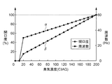
臭気濃度(CIAQ)に対する排気強度の制御パターンの一例を図5に示す。
グラフの横軸は臭気濃度値(CIAQ値)を示し、右側縦軸は周波数(Hz)、左側縦軸は開口度(%)を示す。排気ファン42(モータM2)に印加される電源周波数(以後、周波数と表す)の制御パターンをα、排気ダンパ43の開口度の調節パターンをβで示す。なお、排気ファン42が制御される周波数の範囲は、0Hz(停止状態)〜60Hz(フル運転状態)であるが、商用交流電源を用いる場合には、0〜50Hzの場合であっても良い。
An example of the exhaust intensity control pattern with respect to the odor concentration (CIAQ) is shown in FIG.
The horizontal axis of the graph indicates the odor concentration value (CIAQ value), the right vertical axis indicates the frequency (Hz), and the left vertical axis indicates the degree of opening (%). A control pattern of a power supply frequency (hereinafter referred to as a frequency) applied to the exhaust fan 42 (motor M2) is denoted by α, and an opening degree adjustment pattern of the
図5において、排気ファン42に印加される周波数は、0〜60Hzの範囲を、臭気濃度値に比例した電源周波数で運転される。周波数は、CIAQ10のときに0Hz(停止状態)、CIAQ20のときに30Hz、CIAQ200のときに60Hz(フル運転状態)で運転され、CIAQが20〜200の範囲の値のときには、CIAQ値に比例して、30Hzと60Hzを結んだ線上の値の周波数で運転される。
In FIG. 5, the frequency applied to the
同様に、排気ダンパ43の開口度は、0〜100%の範囲を、臭気濃度に比例した開口度に調節される。開口度は、CIAQ10のときに0%(全閉状態)、CIAQ20のときに15%、CIAQ200のときに100%(全開状態)に調節され、CIAQが20〜200の範囲の値のときには、CIAQ値に比例して、15%と100%を結んだ線上の開口度に調節される。
Similarly, the opening degree of the
そして、重合の開始スイッチ(図示せず)が押されてONすると、重合炉1の全ての装置が稼動して、重合炉本体2の炉室22内の棚27に載置され、熱硬化性組成物が注入されたモールドWの重合が開始する。
Then, when a polymerization start switch (not shown) is pressed and turned on, all the apparatuses in the polymerization furnace 1 are operated and placed on the
重合が開始されると、重合温度パターンTP(図3参照)に基づいて、温度制御装置3に温度制御されて重合が行われると共に、排気調整部48のメモリに格納された臭気濃度の経時変化の予測パターンに基づいて、排気ファン42(モータM2)の電源周波数の制御(インバータ制御)と、排気ダンパ43の開口度の制御(モータM3の制御)が行われる。 When the polymerization is started, the temperature is controlled by the temperature control device 3 based on the polymerization temperature pattern TP (see FIG. 3), and the odor concentration stored in the memory of the exhaust adjustment unit 48 is changed over time. Based on the predicted pattern, control of the power supply frequency of the exhaust fan 42 (motor M2) (inverter control) and control of the opening degree of the exhaust damper 43 (control of the motor M3) are performed.
図6は原料組成物の重合時における排気ファンの電源周波数の制御パターンの一例を示す図であり、グラフの横軸は重合の経過時間を示し、縦軸は周波数(Hz)を示す。図7は原料組成物の重合時における排気ダンパの開口度の調節パターンの一例を示す図であり、グラフの横軸は重合の経過時間を示し、縦軸は開口度(%)を示す。 FIG. 6 is a diagram showing an example of a control pattern of the power supply frequency of the exhaust fan during polymerization of the raw material composition, where the horizontal axis of the graph indicates the elapsed time of polymerization and the vertical axis indicates the frequency (Hz). FIG. 7 is a diagram showing an example of the adjustment pattern of the opening degree of the exhaust damper during the polymerization of the raw material composition. The horizontal axis of the graph shows the elapsed time of polymerization, and the vertical axis shows the opening degree (%).
図6に示す電源周波数の制御パターンFTA,FTB、および図7に示す排気ダンパの開口度の調節パターンOTは、例えば、重合炉1に投入され重合される原料組成物の体積が略24リットルにおける臭気濃度の予測パターンに基づいて制御される場合を例示している。すなわち、臭気濃度の予測パターンは、図4に示す検量線SPAとほぼ同一のパターンの場合である。なお、図6中に示す電源周波数の制御パターンFTBは、比較確認のために、臭気濃度の予測パターンに基づいて、一般的なインバータ制御による電源周波数の制御を行った場合を示している。 The power frequency control patterns FTA, FTB shown in FIG. 6 and the exhaust damper opening degree adjustment pattern OT shown in FIG. 7 are, for example, when the volume of the raw material composition to be introduced into the polymerization furnace 1 and polymerized is approximately 24 liters. The case where it controls based on the prediction pattern of an odor density is illustrated. That is, the prediction pattern of the odor concentration is a pattern that is almost the same as the calibration curve SPA shown in FIG. The power frequency control pattern FTB shown in FIG. 6 shows a case where the power frequency is controlled by general inverter control based on the odor concentration prediction pattern for comparison and confirmation.
排気ファン42の電源周波数の制御は、排気調整部48において、メモリに格納された臭気濃度の予測パターン(図4に示す検量線SPA参照)と電源周波数の制御パターンα(図5参照)に基づいて、重合の経過時間と共に変化する臭気濃度の値に対応した電源周波数が排気ファン42(モータM2)に出力され、電源周波数に対応した回転速度で回転する。
The control of the power supply frequency of the
重合時に排気ファン42が制御される電源周波数の制御パターンFTAは、重合開始直後に略40Hz、臭気濃度がピークに達する略CIAQ190時に略55Hz、重合の終了直前に略40Hzに制御される。排気ファン42が制御される電源周波数の制御パターンFTAは、図6に示すように、一般的なインバータ制御による電源周波数の制御パターンFTBに比べて、10%程度低い周波数で制御される。
The control pattern FTA of the power supply frequency for controlling the
排気ダンパ43の開口度の制御は、排気調整部48において、メモリに格納された臭気濃度の予測パターンと開口度の制御パターンβ(図5参照)に基づいて、経過時間と共に変化する臭気濃度の値に対応した制御電圧がモータM3に出力され、モータM3が制御電圧に対応した調節量、作動して、排気ダンパ43の開口度が制御される。
The control of the opening degree of the
重合時に制御される排気ダンパ43の開口度の調節パターンOTは、図7に示すように、臭気濃度の予測パターンSPAにほぼ沿うように推移し、臭気濃度がピークに達する略CIAQ190時に略95%の開口度に制御される。
As shown in FIG. 7, the adjustment pattern OT of the opening degree of the
排気調整部48の制御に基づいて排気ファン42および排気ダンパ43が作動すると、炉室22の循環空気が排気管41を介して活性炭の充填搭からなる脱臭装置45に導かれ、活性炭の充填搭を通過する際に、活性炭が循環空気に含まれる炭化水素系化合物等の臭気成分を吸着して捕捉する。臭気成分が捕捉されて無臭状態に脱臭された循環空気は、再び排気管41を介して重合炉1外の外部環境に排気される。
When the
また、臭気演算部47は、臭気測定器44において測定された炉室22の循環空気の臭気濃度の現在値(CIAQ値)と、予測パターンの臭気濃度の値(すなわち予測値(CIAQ値))との差を演算し、その値が所定範囲を超えた場合に、排気強度を補正する指示信号を排気調整部48に出力する。前記所定範囲は、原料組成物の重合時における臭気濃度のバラツキの範囲であり、例えば予測値の±15%程度の値である。なお、臭気濃度の現在値と予測値との差が所定範囲を超える場面は、重合される原料組成物に添加される添加剤等の添加量を、正規の添加量と異なる量を添加した場合、あるいは重合炉1を構成する装置の一部に不具合が発生した場合等が想定される。
Further, the odor calculating unit 47 calculates the current value (CIAQ value) of the odor concentration of the circulating air in the
そして、脱臭制御部46は、排気強度を補正する指示信号が入力されると、排気ファン42および排気ダンパ43の排気強度を補正する制御に切り替える。排気強度を補正する制御は、いわゆるON/OFF制御である。
When the instruction signal for correcting the exhaust intensity is input, the
脱臭制御部46は、臭気測定器44において測定された臭気濃度(CIAQ)の現在値が、予測値の+15%を超える値であり、しかも+15%を超える値の絶対値が20以上の場合に、排気ファン42(モータM2)に、60Hzの電源周波数を出力し、排気ファン42をフル回転すると共に、排気ダンパ43(モータM3)を全開(開口度100%)状態にする制御が行われる。
一方、臭気濃度(CIAQ)の現在値が予測値の−15%未満の値であり、しかも−15%未満の値の絶対値が20以上の場合に、排気ファン42(モータM2)に、出力する電源周波数を停止して排気ファン42を停止状態にすると共に、排気ダンパ43(モータM3)を全閉状態(開口度0%)にする制御が行われる。
The
On the other hand, when the current value of the odor concentration (CIAQ) is less than −15% of the predicted value and the absolute value of the value less than −15% is 20 or more, the output is output to the exhaust fan 42 (motor M2). The power supply frequency to be stopped is stopped, the
以上の重合炉の脱臭方法により運転された重合における脱臭制御装置の電力量について説明する。
図8は、原料組成物の重合時における脱臭制御装置4(排気ファン42)の使用電力量の推移を示す図であり、グラフの横軸は重合の経過時間を示し、縦軸は電力量(ワット(W))を示す。なお電力量は、排気ファン42と排気ダンパ43の合計使用電力量であり、重合の経過時間の5分間毎の電力量をプロットした推移である。
The amount of electric power of the deodorization control device in the polymerization operated by the above deodorization method of the polymerization furnace will be described.
FIG. 8 is a graph showing the transition of the amount of electric power used by the deodorization control device 4 (exhaust fan 42) during polymerization of the raw material composition. The horizontal axis of the graph indicates the elapsed time of polymerization, and the vertical axis indicates the electric energy ( Watts (W)). The amount of power is the total amount of power used by the
なお、図中に示す電力量の推移線ETaは、本実施形態における排気ファン42と排気ダンパ43の排気強度の制御、いわゆる予測制御が行われた脱臭制御装置4における推移を示す。推移線ETb、および推移線ETcは、比較のため参考に、実験的に本実施形態の脱臭制御装置4を用いて、排気ファン42の電源周波数を一般的なインバータ制御した場合、および電源周波数を制御しない60Hzの一定電源周波数で運転が行われた場合の電力量の推移を示している。なお、電力量の推移線ETb,ETcは、排気ファン42の電源周波数の制御のみが行われ、排気ダンパ43および吸気ダンパ7の開口度の制御は行わずに、全開口状態に保持された電力量を示す。
In addition, the transition line ETa of the electric energy shown in the figure shows the transition in the deodorization control device 4 in which the exhaust intensity control of the
脱臭制御装置4の使用電力量は、重合時における電源周波数の制御パターンに沿って推移し、図8に示すように、予測制御が行われた推移線ETaは、一般的なインバータ制御が行われた推移線ETb、一定電源周波数で運転が行われた推移線ETcに比べて、低い使用電力量で効率的な省エネルギー運転が得られる。 The amount of power used by the deodorization control device 4 changes according to the control pattern of the power supply frequency at the time of polymerization. As shown in FIG. 8, the transition line ETa on which the predictive control is performed is subjected to general inverter control. Compared with the transition line ETb and the transition line ETc that is operated at a constant power supply frequency, an efficient energy-saving operation can be obtained with a lower power consumption.
こうした各電源周波数の制御による脱臭制御装置4の使用電力量を測定した。測定値は、脱臭制御装置4を備えた重合炉10台の月平均使用電力量であり、一定電源周波数で運転が行われた場合の電力量は8,500kwh/月、一般的なインバータ制御で運転が行われた場合の電力量は4,900kwh/月、電源周波数の予測制御が行われた場合の電力量は、3,880kwh/月であった。電源周波数の予測制御が行われた重合炉の脱臭方法は、従来の方法に比べて約20〜55%の電力量を削減することができる。 The amount of electric power used by the deodorization control device 4 by controlling each power source frequency was measured. The measured value is the monthly average power consumption of 10 polymerization furnaces equipped with the deodorization control device 4, and the power consumption when operated at a constant power supply frequency is 8,500 kwh / month. The amount of power when the operation was performed was 4,900 kwh / month, and the amount of power when the power supply frequency prediction control was performed was 3,880 kwh / month. The deodorizing method for the polymerization furnace in which the power supply frequency prediction control is performed can reduce the amount of power by about 20 to 55% compared to the conventional method.
以上の実施形態によれば、脱臭制御装置4が、予め測定された原料組成物の熱重合時に発生する臭気濃度の発生パターンに基づいた予測パターンに応じて、重合炉1内の雰囲気を排気する排気ファン42及び排気ダンパ43の排気強度を制御すると共に、臭気測定器44の検知した臭気濃度が、予測パターンの所定の範囲を超えた場合に、排気ファン42及び排気ダンパ43の排気強度を補正する制御を行うことにより、無駄な電力を消費することなく省エネルギー運転で、原料組成物の熱重合時に発生する臭気を取り除くことが可能な重合炉1の脱臭方法が得られる。
According to the above embodiment, the deodorization control apparatus 4 exhausts the atmosphere in the polymerization furnace 1 according to the predicted pattern based on the generation pattern of the odor concentration generated during the thermal polymerization of the raw material composition measured in advance. The exhaust intensity of the
以上の実施形態において、脱臭装置45として活性炭の充填搭からなる吸着方式の脱臭装置の場合で説明したが、オゾン酸化法、あるいは光触媒脱臭法の脱臭装置の場合であっても、活性炭の充填搭からなる吸着方式と同様に、排気ファン、排気ダンパの排気強度を予測制御することにより、省エネルギー運転が図られた重合炉の脱臭方法が得られる。
また、温度制御装置3に温度制御部35を備え、脱臭制御装置4に脱臭制御部46を備えた場合で説明したが、温度制御部35と脱臭制御部46を一つの制御部で構成しても良い。
In the above embodiment, the description has been given of the case where the
Further, the temperature control device 3 includes the
また、冷却手段に直接式(直接膨張式)冷凍機を用いた場合で説明したが、間接式(間接膨張式)冷凍機であっても良い。
また、図3に示した、熱硬化性組成物が注入されたモールドWの重合のための重合温度パターンTPは、重合される所望の熱硬化性組成物により異なり、これに限定されず、どんな熱硬化性組成物の場合であっても良い。
Moreover, although the direct type (direct expansion type) refrigerator was used for the cooling means, an indirect type (indirect expansion type) refrigerator may be used.
Also, the polymerization temperature pattern TP for the polymerization of the mold W injected with the thermosetting composition shown in FIG. 3 depends on the desired thermosetting composition to be polymerized, and is not limited to this. It may be a case of a thermosetting composition.
また、熱硬化性組成物は、2種以上の重合性単量体から構成されるプラスチックレンズ用組成物であれば、どんな組成物の、どんな組み合わせの場合であっても良いし、重合処理される熱硬化性組成物が注入されたモールドWを構成する2つのガラス型80,81の固定は、粘着剤が塗布された粘着テープを用いた構成の場合で説明したが、従来一般的に用いられているガスケットを用いた構成であっても良い。
Further, the thermosetting composition may be any composition in any combination as long as it is a composition for plastic lenses composed of two or more kinds of polymerizable monomers. The fixing of the two
1…重合炉、2…重合炉本体、3…温度制御装置、4…脱臭制御装置、5…操作部、6…吸気管、7…吸気ダンパ、21…断熱壁、22…炉室、23…ヒータ、24…ラジエタ、25…制御用温度センサ、26…ファン、27…棚、28…空気取入れ口、29…排気口、31…冷却装置、32…戻り管、33…供給管、34…熱媒体温度センサ、35…温度制御部、36…温度演算部、37…温度調整部、41…排気流路としての排気管、42…排気ファン、43…排気ダンパ、44…臭気測定器、45…脱臭装置、46…脱臭制御部、47…臭気演算部、48…排気調整部、80,81…ガラス型、82…粘着テープ、83…原料組成物としての熱硬化性組成物、W…モールド、TP…重合温度パターン、SPA,SPB,SPC…臭気濃度の発生パターン(検量線)、FTA,FTB…電源周波数の制御パターン、OT…排気ダンパの開口度の調節パターン、α…電源周波数の制御パターン、β…排気ダンパの開口度の調節パターン。
DESCRIPTION OF SYMBOLS 1 ... Polymerization furnace, 2 ... Polymerization furnace main body, 3 ... Temperature control apparatus, 4 ... Deodorization control apparatus, 5 ... Operation part, 6 ... Intake pipe, 7 ... Intake damper, 21 ... Heat insulation wall, 22 ... Furnace chamber, 23 ... Heater, 24 ... Radiator, 25 ... Temperature sensor for control, 26 ... Fan, 27 ... Shelf, 28 ... Air intake port, 29 ... Exhaust port, 31 ... Cooling device, 32 ... Return pipe, 33 ... Supply pipe, 34 ... Heat
Claims (4)
前記重合炉は、
重合炉内の雰囲気を排気する排気ファンと、
前記重合炉内の前記雰囲気を前記排気ファンに導くための排気流路と、
前記排気流路上に前記排気流路を流れる前記雰囲気の排気量を開口度で制御する排気ダンパと、
前記排気ダンパの上流側の前記排気流路上に前記重合炉内の臭気濃度を検知する臭気測定器と、
前記排気ダンパの下流側の前記排気流路上に前記雰囲気中に含まれる臭気を除去する脱臭装置と、
前記臭気測定器の検知した臭気濃度に基づいて前記排気ファン及び前記排気ダンパの排気強度を制御する臭気制御部と、
を備え、
前記臭気制御部は、
予め測定された前記原料組成物の熱重合時に発生する臭気濃度の発生パターンに基づいて臭気濃度の予測パターンを演算し、
演算された前記臭気濃度の予測パターンに応じて前記排気強度を制御すると共に、
前記臭気測定器の検知した臭気濃度が、前記予測パターンの所定の範囲を超えた場合に、前記排気強度を補正する制御を行うことを特徴とする重合炉の脱臭方法。 A deodorizing method for a polymerization furnace for thermally polymerizing a raw material composition,
The polymerization furnace is
An exhaust fan for exhausting the atmosphere in the polymerization furnace;
An exhaust passage for guiding the atmosphere in the polymerization furnace to the exhaust fan;
An exhaust damper for controlling an exhaust amount of the atmosphere flowing through the exhaust passage on the exhaust passage with an opening degree;
An odor measuring device for detecting an odor concentration in the polymerization furnace on the exhaust passage upstream of the exhaust damper;
A deodorizing device for removing odors contained in the atmosphere on the exhaust flow path downstream of the exhaust damper;
An odor control unit that controls exhaust strength of the exhaust fan and the exhaust damper based on the odor concentration detected by the odor measuring device;
With
The odor control unit is
Calculate the predicted pattern of odor concentration based on the odor concentration generation pattern generated during the thermal polymerization of the raw material composition measured in advance,
While controlling the exhaust intensity according to the calculated prediction pattern of the odor concentration,
A deodorizing method for a polymerization furnace, wherein control is performed to correct the exhaust gas intensity when an odor concentration detected by the odor measuring device exceeds a predetermined range of the predicted pattern.
The method for deodorizing a polymerization furnace according to any one of claims 1 to 3, wherein the raw material composition is a composition for plastic lenses composed of two or more kinds of polymerizable monomers.
Priority Applications (1)
| Application Number | Priority Date | Filing Date | Title |
|---|---|---|---|
| JP2005198391A JP2007014875A (en) | 2005-07-07 | 2005-07-07 | Method for deodorizing polymerization furnace |
Applications Claiming Priority (1)
| Application Number | Priority Date | Filing Date | Title |
|---|---|---|---|
| JP2005198391A JP2007014875A (en) | 2005-07-07 | 2005-07-07 | Method for deodorizing polymerization furnace |
Publications (1)
| Publication Number | Publication Date |
|---|---|
| JP2007014875A true JP2007014875A (en) | 2007-01-25 |
Family
ID=37752485
Family Applications (1)
| Application Number | Title | Priority Date | Filing Date |
|---|---|---|---|
| JP2005198391A Withdrawn JP2007014875A (en) | 2005-07-07 | 2005-07-07 | Method for deodorizing polymerization furnace |
Country Status (1)
| Country | Link |
|---|---|
| JP (1) | JP2007014875A (en) |
Cited By (2)
| Publication number | Priority date | Publication date | Assignee | Title |
|---|---|---|---|---|
| WO2013105296A1 (en) * | 2012-01-13 | 2013-07-18 | 株式会社島津製作所 | Auto-sampler |
| EP2452241A4 (en) * | 2009-07-09 | 2016-03-30 | Odotech Inc | System and method for dynamically controlling odor emission |
-
2005
- 2005-07-07 JP JP2005198391A patent/JP2007014875A/en not_active Withdrawn
Cited By (3)
| Publication number | Priority date | Publication date | Assignee | Title |
|---|---|---|---|---|
| EP2452241A4 (en) * | 2009-07-09 | 2016-03-30 | Odotech Inc | System and method for dynamically controlling odor emission |
| WO2013105296A1 (en) * | 2012-01-13 | 2013-07-18 | 株式会社島津製作所 | Auto-sampler |
| EP2803993A4 (en) * | 2012-01-13 | 2015-06-17 | Shimadzu Corp | Auto-sampler |
Similar Documents
| Publication | Publication Date | Title |
|---|---|---|
| CN105352239B (en) | The control method of air conditioner electronic expansion valve | |
| CN105299974B (en) | A kind of control method of air conditioner electronic expansion valve | |
| JP2006275460A (en) | Air conditioning system and its method | |
| CN104764162B (en) | A kind of energy-saving control method of air-conditioner, control system and air-conditioner | |
| CN110454933A (en) | Air-conditioning and its mildew-proof control method, computer equipment, readable storage medium storing program for executing | |
| JP2006258340A (en) | Air-conditioner | |
| CN112129914A (en) | Rapid cooling device of strip steel heat treatment process simulation experiment device and working method | |
| JP2007014875A (en) | Method for deodorizing polymerization furnace | |
| CN109341006B (en) | Variable frequency air conditioner control device and control method | |
| CN1181299C (en) | Method and apparatus for controlling temperature and humidity, or temperature | |
| CN110487020B (en) | Frequency control method for frequency conversion refrigerator | |
| KR101330525B1 (en) | Temperature adjusting apparatus for mold and the method thereof | |
| CN111720986A (en) | Temperature control method and device, electronic equipment and storage medium | |
| JPS63242333A (en) | Control apparatus for kneader | |
| CN107500519B (en) | Glass plate tempering process control method | |
| JP2003025404A (en) | Molding machine | |
| JP2006329529A (en) | Heat medium circulating type heating apparatus | |
| KR100371896B1 (en) | Heating control method making use of temperature measuring period | |
| JP5271726B2 (en) | Stop time estimation apparatus and estimation method | |
| CN104864565B (en) | The control method of air-conditioner set | |
| CN111637633A (en) | Control method for constant-temperature backwater of solid regenerative furnace | |
| JP2000146878A (en) | Sample temperature controlling method | |
| CN111360994A (en) | Automatic heating and humidifying system for prefabricated part in closed space | |
| JPH06294542A (en) | Control method of airconditioning apparatus | |
| JP2009236454A (en) | Temperature controller |
Legal Events
| Date | Code | Title | Description |
|---|---|---|---|
| A300 | Withdrawal of application because of no request for examination |
Free format text: JAPANESE INTERMEDIATE CODE: A300 Effective date: 20081007 |