JP2007014101A - Motor actuator - Google Patents
Motor actuator Download PDFInfo
- Publication number
- JP2007014101A JP2007014101A JP2005190597A JP2005190597A JP2007014101A JP 2007014101 A JP2007014101 A JP 2007014101A JP 2005190597 A JP2005190597 A JP 2005190597A JP 2005190597 A JP2005190597 A JP 2005190597A JP 2007014101 A JP2007014101 A JP 2007014101A
- Authority
- JP
- Japan
- Prior art keywords
- motor
- terminal
- actuator
- connector terminal
- actuator connector
- Prior art date
- Legal status (The legal status is an assumption and is not a legal conclusion. Google has not performed a legal analysis and makes no representation as to the accuracy of the status listed.)
- Pending
Links
Images


Abstract
Description
本発明はモータアクチュエータに関し、特に、自動車用空調装置における通風路の切り替え等を行うドアの制御等に利用されるモータアクチュエータに関する。 The present invention relates to a motor actuator, and more particularly, to a motor actuator used for controlling a door that performs switching of an air passage in an automotive air conditioner.
一般に、この種のモータアクチュエータは、ドアの駆動力を発生するモータを備えており、その内部では、コネクタのアクチュエータ端子からモータに給電するアクチェータコネクタ端子がモータ端子に接続されている。このモータ端子とアクチェータコネクタ端子との接続には、はんだ付けが一般に使用されている。 In general, this type of motor actuator includes a motor that generates a driving force of a door, and an actuator connector terminal that supplies power to the motor from the actuator terminal of the connector is connected to the motor terminal. Soldering is generally used for connection between the motor terminal and the actuator connector terminal.
図8は、従来のモータアクチュエータの、上部カバーを外した状態の平面図、図9は、図8のD−D矢視断面図である。
図8に示すように、モータアクチュエータは、ケース1と、このケース1内に収納されたモータ2と、このモータ2の出力軸3に取り付けられたウォームギヤ4に順次噛み合うよう構成された減速歯車5,6,7とを備えている。モータ2は、その後部に一対の板状のモータ端子8,8が設けられている。このモータ端子8,8とコネクタのアクチュエータ端子との間には、一対のアクチェータコネクタ端子9が配置されている。
FIG. 8 is a plan view of the conventional motor actuator with the upper cover removed, and FIG. 9 is a cross-sectional view taken along line DD in FIG.
As shown in FIG. 8, the motor actuator includes a
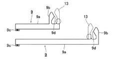
図9に示すように、アクチェータコネクタ端子9は、そのモータ側先端に中央にスリットを構成するように一対の接続片13,14が一体に形成されており、この接続片13,14の間のスリットに板状のモータ端子8,8を圧入し、最終的に、その圧入部分をはんだ付けすることによってアクチェータコネクタ端子9とモータ端子8,8とを電気的に接続している。
As shown in FIG. 9, the
また、このはんだ付けによるアクチェータコネクタ端子とモータ端子との接続以外に、クリップ状のばね接点を用いる方法も知られている(例えば、特許文献1参照)。この接続方法は、アクチェータコネクタ端子にクリップ状のばね接点を設け、そのばね接点が板状のモータ端子を両面から挟持するようにし、ばね接点のばね力によるモータ端子への圧接により電気的に接続するようにしている。
近年の環境上の理由から、はんだ付けには、鉛フリーのはんだを使用するようになってきている。しかしながら、鉛フリーのはんだは、未だ技術的に確立していないので、はんだ接合時に濡れ性のばらつきによる接合不良が生じてしまうとともに、融点の仕様が高温のため設備への負担が大きく、かつはんだ自体のコストも高いという問題点があった。 For environmental reasons in recent years, lead-free solder has been used for soldering. However, since lead-free solder has not been technically established, joint failure may occur due to variation in wettability during solder joining, and the melting point specification is high, and the burden on the equipment is large. There was a problem that the cost of itself was high.
また、特許文献1に記載されているようなばね接点を用いるものは、ばね接点を別部品としてアクチェータコネクタ端子に取り付ける必要があるため、部品点数がそれだけ増えるとともに、ばね接点をかしめ、モールド等により取り付けるため製造コストも高くなるという問題点があった。
In addition, those using a spring contact as described in
本発明は、このような点に鑑みてなされたものであり、接続信頼性が高く、かつ部品コストおよび加工コストを抑制することを可能にしたモータアクチュエータを提供することを目的とする。 The present invention has been made in view of the above points, and an object of the present invention is to provide a motor actuator that has high connection reliability and that can suppress component costs and processing costs.
本発明では上記問題を解決するために、モータ端子に給電用のアクチェータコネクタ端子を接続したモータアクチュエータにおいて、前記モータ端子と前記アクチェータコネクタ端子とをスポット溶接により接続したことを特徴とするモータアクチュエータが提供される。 In the present invention, in order to solve the above problem, a motor actuator having a power supply actuator connector terminal connected to a motor terminal, wherein the motor terminal and the actuator connector terminal are connected by spot welding. Provided.
このようなモータアクチュエータによれば、モータ端子とアクチェータコネクタ端子とを当接させ、両側から溶接電極を当ててスポット溶接することにより、両端子を接続することができる。 According to such a motor actuator, the motor terminal and the actuator connector terminal are brought into contact with each other, and both terminals can be connected by spot welding by applying the welding electrode from both sides.
本発明のモータアクチュエータは、モータ端子とアクチェータコネクタ端子とがスポット溶接により接続するので、鉛フリーのはんだによるはんだ付けに比べて接続信頼性が高く、また、アクチェータコネクタ端子は1部品でよいので、部品コストが安く、かつアクチェータコネクタ端子の加工コストも抑制することができる。 In the motor actuator of the present invention, since the motor terminal and the actuator connector terminal are connected by spot welding, the connection reliability is high compared to soldering by lead-free solder, and the actuator connector terminal may be a single component. The parts cost is low and the machining cost of the actuator connector terminal can be suppressed.
以下、本発明の実施の形態を、図面を参照して詳細に説明する。
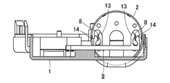
図1は、本発明のモータアクチュエータの第1の実施の形態を示す、上部カバーを外した状態の平面図、図2は、図1のA−A矢視断面図、図3は、第1の実施の形態のモータアクチュエータの溶接工程を示す平面図、図4は、図3のB−B矢視断面図である。なお、図1ないし図4において、図8および図9と同一部品、同一機能のものは同一符号で示している。
Hereinafter, embodiments of the present invention will be described in detail with reference to the drawings.
FIG. 1 is a plan view showing a motor actuator according to a first embodiment of the present invention with a top cover removed, FIG. 2 is a cross-sectional view taken along the line AA in FIG. 1, and FIG. The top view which shows the welding process of the motor actuator of embodiment of this, FIG. 4 is BB arrow sectional drawing of FIG. 1 to 4, the same parts and functions as those in FIGS. 8 and 9 are denoted by the same reference numerals.
図1および図2に示すように、このモータアクチュエータは、ケース1と、このケース1内に収納されたモータ2と、このモータ2の出力軸3に取り付けられたウォームギヤ4に順次噛み合うよう構成された減速歯車5,6,7とを備えている。ケース1は、その上端縁に段部1aが周設されており、その段部1aに上部カバー(図示せず)を被せることにより、ケース1および上部カバーの外周部に一体に形成された複数のフックが互いに嵌合されてケース1と上部カバーとが固定されることによりモータアクチュエータを構成するようになっている。
As shown in FIGS. 1 and 2, the motor actuator is configured to sequentially mesh with a
モータ2は、その後部に一対のモータ端子8,8が突設されている。このモータ端子8,8は、それぞれ互いに対向した板状の形状を有しており、これに一対のアクチェータコネクタ端子9,9が接続されている。
The
アクチェータコネクタ端子9は、細長い板状の端子本体部9aと、モータ側の先端に設けられた接続部9bと、基端部に設けられたコネクタピン9cとが一体になった1部品で構成されている。接続部9bは、図2に示すように、端子本体部9aの先端部から端子本体部9aと同一面をなすように立ち上がり、モータ端子8の面に対してほぼ直角になっている。また、接続部9bは、モータ端子8に向く側の端縁部が、側面ほぼ三角状の突起部9dが形成されていて、モータ端子8の面に点接触するようにしている。コネクタピン9cは、図1に示すように、端子本体部9aの基端部から外側方向に直角に折り曲げられて、ケース1および上部カバーの側部に一体に形成されたコネクタハウジング10の内部に突出している。
The
アクチェータコネクタ端子9とモータ端子8との接続は、図3および図4に示すように、突起部9dの頂点をモータ端子8の面に当接させ、モータ端子8および接続部9bに対して両側から溶接電極11,11で加圧しながら、溶接電極11,11に溶接電流を流す。これにより、モータ端子8と突起部9dとの点接触部分に電流が集中して流れ、スポット溶接が行われる。
As shown in FIGS. 3 and 4, the
図5は、アクチェータコネクタ端子の別の例を示す図である。
このアクチェータコネクタ端子9は、破線で示した接続片13を含んだものが従来、はんだ付けされていたもの(図9参照)と同じものであり、その形状のものから円で示した部分をプレスで打ち抜くことによって形成している。このように、従来の形状のものであっても、モータ端子8の内側に位置する接続片13をそれぞれ除去することによって、従来のアクチェータコネクタ端子を無駄にすることなく、スポット溶接対応のアクチェータコネクタ端子9に変更することができる。
FIG. 5 is a diagram illustrating another example of the actuator connector terminal.
The
図6は、本発明のモータアクチュエータの第2の実施の形態を示す、上部カバーを外した状態の平面図、図7は、図6のC−C矢視断面図である。
第2の実施の形態では、アクチェータコネクタ端子9は、その接続部における接続の信頼性を改善した構造にしている。すなわち、このアクチェータコネクタ端子9は、端子本体部9aの先端を、端子本体部9aの面に対してモータ2の方向に直角に折り曲げ、さらにその折り曲げた部分をモータ端子8より上方に延出させて接続部9bを形成している。この接続部9bは、また、モータ端子8と対向する部分にモータ端子8の側に突出したリブ9eが形成されている。これにより、接続部9bのリブ9eがモータ端子8の平面部と線接触の状態になる。
FIG. 6 is a plan view of the motor actuator according to the second embodiment of the present invention with the top cover removed, and FIG. 7 is a cross-sectional view taken along the line CC in FIG.
In the second embodiment, the
このアクチェータコネクタ端子9においても、図7に示すように、リブ9eの稜線をモータ端子8の面に当接させ、モータ端子8および接続部9bに対して両側から溶接電極11,11で加圧しながら、溶接電極11,11に溶接電流を流すことにより、モータ端子8と突起部9dとがスポット溶接される。
Also in this
このように、第1の実施の形態ではモータ端子8とアクチェータコネクタ端子9の突起部9dが点接触に近い状態でスポット溶接されるのに対し、第2の実施の形態では、リブ9eにより線接触でスポット溶接されるため、スポット溶接の部分の面積が大きくなり、接続の信頼性がより向上する。
In this way, in the first embodiment, the
1 ケース
1a 段部
2 モータ
3 出力軸
4 ウォームギヤ
5,6,7 減速歯車
8 モータ端子
9 アクチェータコネクタ端子
9a 端子本体部
9b 接続部
9c コネクタピン
9d 突起部
9e リブ
10 コネクタハウジング
DESCRIPTION OF
Claims (3)
前記モータ端子と前記アクチェータコネクタ端子とをスポット溶接により接続したことを特徴とするモータアクチュエータ。 In the motor actuator where the actuator connector terminal for power supply is connected to the motor terminal,
A motor actuator, wherein the motor terminal and the actuator connector terminal are connected by spot welding.
The actuator connector terminal has a plate-like connection portion bent at a substantially right angle with respect to the surface of the terminal main body at the tip of the terminal main body portion, and is formed on the surface of the connection portion facing the motor terminal. The motor actuator according to claim 1, wherein a rib is formed, and the rib is spot welded to the motor terminal.
Priority Applications (1)
| Application Number | Priority Date | Filing Date | Title |
|---|---|---|---|
| JP2005190597A JP2007014101A (en) | 2005-06-29 | 2005-06-29 | Motor actuator |
Applications Claiming Priority (1)
| Application Number | Priority Date | Filing Date | Title |
|---|---|---|---|
| JP2005190597A JP2007014101A (en) | 2005-06-29 | 2005-06-29 | Motor actuator |
Publications (1)
| Publication Number | Publication Date |
|---|---|
| JP2007014101A true JP2007014101A (en) | 2007-01-18 |
Family
ID=37751823
Family Applications (1)
| Application Number | Title | Priority Date | Filing Date |
|---|---|---|---|
| JP2005190597A Pending JP2007014101A (en) | 2005-06-29 | 2005-06-29 | Motor actuator |
Country Status (1)
| Country | Link |
|---|---|
| JP (1) | JP2007014101A (en) |
Cited By (5)
| Publication number | Priority date | Publication date | Assignee | Title |
|---|---|---|---|---|
| JP2013198332A (en) * | 2012-03-21 | 2013-09-30 | Hitachi Automotive Systems Ltd | Electric actuator and method for manufacturing electric actuator |
| JP2015104223A (en) * | 2013-11-25 | 2015-06-04 | アスモ株式会社 | Motor actuator |
| JP2015142490A (en) * | 2014-01-30 | 2015-08-03 | 株式会社テージーケー | motor actuator and terminal |
| KR101689549B1 (en) * | 2015-07-09 | 2016-12-27 | 계양전기 주식회사 | Electric Parking Brake Actuator with Housing Cover Formed Connector |
| JP2017158345A (en) * | 2016-03-03 | 2017-09-07 | 株式会社テージーケー | Relay terminal and motor actuator |
Citations (7)
| Publication number | Priority date | Publication date | Assignee | Title |
|---|---|---|---|---|
| JPS6210979U (en) * | 1985-07-03 | 1987-01-23 | ||
| JPH0439060U (en) * | 1990-07-30 | 1992-04-02 | ||
| JPH0963658A (en) * | 1995-08-29 | 1997-03-07 | Yamatake Honeywell Co Ltd | Connection structure of lead wire |
| JPH09219957A (en) * | 1995-12-04 | 1997-08-19 | Asmo Co Ltd | Motor actuator and its manufacture |
| JPH10252506A (en) * | 1997-03-07 | 1998-09-22 | Unisia Jecs Corp | Electric control throttle device |
| JP2000201448A (en) * | 1999-01-06 | 2000-07-18 | Tgk Co Ltd | Motor actuator |
| JP2005069292A (en) * | 2003-08-21 | 2005-03-17 | Tgk Co Ltd | Motor actuator |
-
2005
- 2005-06-29 JP JP2005190597A patent/JP2007014101A/en active Pending
Patent Citations (7)
| Publication number | Priority date | Publication date | Assignee | Title |
|---|---|---|---|---|
| JPS6210979U (en) * | 1985-07-03 | 1987-01-23 | ||
| JPH0439060U (en) * | 1990-07-30 | 1992-04-02 | ||
| JPH0963658A (en) * | 1995-08-29 | 1997-03-07 | Yamatake Honeywell Co Ltd | Connection structure of lead wire |
| JPH09219957A (en) * | 1995-12-04 | 1997-08-19 | Asmo Co Ltd | Motor actuator and its manufacture |
| JPH10252506A (en) * | 1997-03-07 | 1998-09-22 | Unisia Jecs Corp | Electric control throttle device |
| JP2000201448A (en) * | 1999-01-06 | 2000-07-18 | Tgk Co Ltd | Motor actuator |
| JP2005069292A (en) * | 2003-08-21 | 2005-03-17 | Tgk Co Ltd | Motor actuator |
Cited By (5)
| Publication number | Priority date | Publication date | Assignee | Title |
|---|---|---|---|---|
| JP2013198332A (en) * | 2012-03-21 | 2013-09-30 | Hitachi Automotive Systems Ltd | Electric actuator and method for manufacturing electric actuator |
| JP2015104223A (en) * | 2013-11-25 | 2015-06-04 | アスモ株式会社 | Motor actuator |
| JP2015142490A (en) * | 2014-01-30 | 2015-08-03 | 株式会社テージーケー | motor actuator and terminal |
| KR101689549B1 (en) * | 2015-07-09 | 2016-12-27 | 계양전기 주식회사 | Electric Parking Brake Actuator with Housing Cover Formed Connector |
| JP2017158345A (en) * | 2016-03-03 | 2017-09-07 | 株式会社テージーケー | Relay terminal and motor actuator |
Similar Documents
| Publication | Publication Date | Title |
|---|---|---|
| US6997750B2 (en) | Electrical connector contact | |
| JP2008544450A (en) | Press-fit pin | |
| JP2006202617A (en) | Manufacturing method of connector terminal and connector terminal | |
| JP6311939B2 (en) | Method for manufacturing female terminal and female terminal | |
| JP2007014101A (en) | Motor actuator | |
| JP2006278336A (en) | Electric connector jack | |
| JP4923188B2 (en) | Motor actuator | |
| JP2008243745A (en) | Connector, and its mounting method | |
| JP5093462B2 (en) | Tab terminal and battery using the same | |
| JP2009283367A (en) | Battery direct-mounting fuse unit | |
| JP2008123922A (en) | Connection structure of terminal, connecting method of same, and control device | |
| JP4681350B2 (en) | Electrical junction box | |
| JP7036779B2 (en) | Relay terminal and manufacturing method of relay terminal | |
| JP4723907B2 (en) | Electrical junction box | |
| JP2007317445A (en) | Connector | |
| JP2010080574A (en) | Joining structure and joining method of bus bar | |
| JP2009076224A (en) | Connection structure between electric wire and printed circuit board | |
| JP2007317457A (en) | Terminal joint structure and terminal | |
| KR20170034141A (en) | A contacting structure of a high voltage terminal in an inverter of a electric compressor | |
| WO2018061490A1 (en) | Connection terminal assembled body and circuit board using same connection terminal assembled body | |
| JP2004076882A (en) | Alloy wire fastening method | |
| JP2005323441A (en) | Connecting structure of press fit terminal to bus bar and connecting method | |
| JP7023070B2 (en) | motor | |
| JP5187103B2 (en) | Electrical junction box | |
| JP2019021544A (en) | Electric connector and manufacturing method thereof |
Legal Events
| Date | Code | Title | Description |
|---|---|---|---|
| A621 | Written request for application examination |
Effective date: 20080521 Free format text: JAPANESE INTERMEDIATE CODE: A621 |
|
| A977 | Report on retrieval |
Free format text: JAPANESE INTERMEDIATE CODE: A971007 Effective date: 20110113 |
|
| A131 | Notification of reasons for refusal |
Free format text: JAPANESE INTERMEDIATE CODE: A131 Effective date: 20110125 |
|
| A02 | Decision of refusal |
Effective date: 20110726 Free format text: JAPANESE INTERMEDIATE CODE: A02 |