JP2007010554A - Positioning device - Google Patents
Positioning device Download PDFInfo
- Publication number
- JP2007010554A JP2007010554A JP2005193625A JP2005193625A JP2007010554A JP 2007010554 A JP2007010554 A JP 2007010554A JP 2005193625 A JP2005193625 A JP 2005193625A JP 2005193625 A JP2005193625 A JP 2005193625A JP 2007010554 A JP2007010554 A JP 2007010554A
- Authority
- JP
- Japan
- Prior art keywords
- positioning
- calculating
- time constant
- reliability
- receiver
- Prior art date
- Legal status (The legal status is an assumption and is not a legal conclusion. Google has not performed a legal analysis and makes no representation as to the accuracy of the status listed.)
- Pending
Links
Images
Landscapes
- Position Fixing By Use Of Radio Waves (AREA)
Abstract
Description
本発明は、衛星が送信する信号を受信して測位を行う測位装置に関する。 The present invention relates to a positioning device that performs positioning by receiving a signal transmitted by a satellite.
衛星測位システム(GPS)は、複数の衛星から送信される信号を受信し、受信信号に含まれる情報から各衛星の軌道情報と各衛星までの擬似距離に基づいて測位計算を行う測位手段を有する測位装置である。近年、携帯電話、車両などのあらゆる物の位置検出にGPSを利用した測位装置が広く用いられるようになった。 The satellite positioning system (GPS) has positioning means for receiving signals transmitted from a plurality of satellites and performing positioning calculation based on the orbit information of each satellite and the pseudo distance to each satellite from the information included in the received signal. It is a positioning device. In recent years, positioning devices using GPS have been widely used to detect the position of all objects such as mobile phones and vehicles.
測位装置を搭載した移動体が移動する場合において、衛星から送信されるGPS信号の状態が変化し、何らかの物陰に入ることでGPS信号が途絶える場合や、GPS信号が何らかの物体(例えば、ビルなど)に反射して多重経路でGPS信号が測位装置に受信される場合(例えば、マルチパスなど)が生じる。このような、測位装置へのGPS信号の遮断やマルチパスが生じると、測位結果が不連続に変化し、移動体位置(以下、ユーザ位置という)の位置跳び現象が現れる。 When a mobile object equipped with a positioning device moves, the state of the GPS signal transmitted from the satellite changes and the GPS signal is interrupted by entering some shadow, or the GPS signal is some object (for example, a building) When a GPS signal is received by a positioning device through multiple paths (for example, multipath). When such GPS signal blocking or multipath occurs to the positioning device, the positioning result changes discontinuously, and a position jump phenomenon of the moving body position (hereinafter referred to as the user position) appears.
そこで、このような問題を解決する技術が、特許文献1に示されている。特許文献1には、測位手段により求められた受信点の位置を当該位置の所定時間間隔における移動距離と、GPS信号のキャリアのドップラー周波数から求めた所定時間間隔における移動距離と、で平滑化する技術が示されている。この技術を用いることにより、受信点の移動に伴うユーザ位置の変化が滑らかに出力されるようにした測位装置とすることが可能とされている。
Therefore,
しかし、特許文献1に示された技術では、移動に伴うユーザ位置の変化を滑らかにするだけであり、測位結果の精度向上にはならないという問題があった。
However, the technique disclosed in
具体的には、平滑化の指標である時定数Tを大きくするほど、速度V(t)の平滑化が強く働き、位置P(t)誤差の削減効果が大きい。しかし、速度V(t)誤差は比較的小さいものの、平滑化を継続すると、その小さいV(t)誤差が、時間tとともに累積され、平滑化により補正位置P’(t)にその誤差を増やしていってしまい、逆に悪化させてしまう懸念がある。 Specifically, as the time constant T, which is an index of smoothing, is increased, the smoothing of the speed V (t) works more strongly and the effect of reducing the position P (t) error is greater. However, although the speed V (t) error is relatively small, if smoothing is continued, the small V (t) error is accumulated with time t, and the error is increased to the correction position P ′ (t) by smoothing. There is a concern that it will get worse and worse.
このように、両誤差の影響は相反する特性であり、現状よりも時定数Tを延長しても、両誤差ともに十分に除去し、さらに測位精度を改善することは困難になっている。また、平滑化に伴い実際の測位結果が遅れるという問題もある。 Thus, the effects of both errors are contradictory characteristics, and even if the time constant T is extended as compared with the current situation, it is difficult to sufficiently remove both errors and further improve the positioning accuracy. There is also a problem that the actual positioning result is delayed with smoothing.
以上のような問題を解決するために、本発明に係る測位装置は、移動体に搭載され、複数の衛星からの信号を受信する受信機と、受信した信号から測位に用いられるコード擬似距離及びキャリアのドップラー周波数などを検出して受信機の位置を求める測位手段と、を有する測位装置において、衛星から受信機までの擬似距離を算出する擬似距離算出手段と、複数の擬似距離から受信機の位置情報を算出する測位算出手段と、キャリアのドップラー周波数から受信機の移動速度を算出する移動速度算出手段と、算出された受信機の位置情報と移動速度の相関値を位置情報の信頼度として算出する測位信頼度算出手段と、算出された信頼度と反比例関係となる時定数を、位置変化の時定数として算出する時定数算出手段と、時定数算出手段からの時定数により、測位算出手段からの位置情報を補正する補正位置算出手段と、を有することを特徴とする。 In order to solve the problems as described above, a positioning device according to the present invention is mounted on a mobile body and receives a signal from a plurality of satellites, a code pseudo distance used for positioning from the received signals, and Positioning means for detecting the carrier Doppler frequency and the like to determine the position of the receiver, in the positioning device, the pseudo distance calculation means for calculating the pseudo distance from the satellite to the receiver, the receiver of the receiver from a plurality of pseudo distance Positioning calculation means for calculating position information, movement speed calculation means for calculating the moving speed of the receiver from the carrier Doppler frequency, and the correlation value between the calculated position information of the receiver and the moving speed as the reliability of the position information Positioning reliability calculation means for calculating, time constant calculating means for calculating a time constant that is inversely proportional to the calculated reliability as a time constant of position change, and time constant calculating means The time constant, and having a correction position calculating means for correcting the position information from the positioning calculating means.
また、本発明に係る測位装置において、測位信頼度算出手段は、算出された受信機の位置情報と移動速度を用いて、一定距離毎に走行した位置と移動速度の軌跡から相関値を求め、位置情報の信頼度として算出することを特徴とする。 Further, in the positioning device according to the present invention, the positioning reliability calculation means obtains a correlation value from the traveled position and the trajectory of the moving speed using the calculated position information and moving speed of the receiver, It is calculated as the reliability of the position information.
さらに、本発明に係る測位装置において、移動速度算出手段からの移動速度を積算して積算速度を算出する積算速度算出手段を有し、積算速度算出手段は、時定数算出手段からの時定数により位置と積算速度との差分となるオフセットを平滑化することを特徴とする。 Further, the positioning device according to the present invention has integrated speed calculating means for calculating the integrated speed by integrating the moving speed from the moving speed calculating means, and the integrated speed calculating means is based on the time constant from the time constant calculating means. It is characterized in that an offset which is a difference between the position and the integrated speed is smoothed.
さらにまた、本発明に係る測位装置において、測位信頼度算出手段は、移動体の運動状態を測定するセンサなどから得られた移動速度と、測位算出手段からの位置情報と、の相関値を位置情報の信頼度として算出することを特徴とする。 Furthermore, in the positioning device according to the present invention, the positioning reliability calculation means calculates the correlation value between the movement speed obtained from a sensor or the like that measures the motion state of the moving body and the position information from the positioning calculation means. It is calculated as the reliability of information.
走行中の位置P(t)の走行軌跡は、速度V(t)の走行軌跡とその形状を比較すると、本来は一致するが、マルチパスによる誤差が多いときは、位置P(t)の軌跡が正しい形状と異なってしまうことが目立ち、結果的に、両者の軌跡形状の相違が増える特徴がある。 The travel locus of the traveling position P (t) is essentially the same when compared with the travel locus of the speed V (t), but when there are many errors due to multipath, the locus of the position P (t). Is conspicuously different from the correct shape, and as a result, there is a feature that the difference between the trajectory shapes increases.
そこで、本発明に係る測位装置は、測位信頼度算出部で、測位計算部で得られた位置P(t)及び速度V(t)を用いて、一定距離走行したこの両者の軌跡形状の相関値を位置P(t)の信頼度S(t)として算出する。さらに、時定数設定部では、前記信頼度S(t)と反比例関係となる時定数T(t)を決定することを特徴とする。 Therefore, in the positioning device according to the present invention, the positioning reliability calculation unit uses the position P (t) and the speed V (t) obtained by the positioning calculation unit to correlate the trajectory shapes of both of them that have traveled for a certain distance. The value is calculated as the reliability S (t) of the position P (t). Furthermore, the time constant setting unit determines a time constant T (t) that is inversely proportional to the reliability S (t).
本発明を用いると、移動に伴う測位結果の変化を滑らかにするだけでなく測位結果の精度向上が実現可能となる。例えば、従来よりも時定数Tを延長しても、ユーザ位置P(t)の誤差が大きいと判断した場合は、時定数T(t)=Tが大きく設定されることで、好適に制御される。また、ユーザ位置P(t)の誤差がほぼ0で正しいと判断した場合は、T(t)≒1と小さくなり、補正位置P’(t)=ユーザ位置P(t)でユーザ速度ベクトルV(t)誤差の累積は防がれ、従来よりも補正位置P’(t)の測位精度が改善できるだけでなく、測位結果の遅延も改善可能となる。 By using the present invention, it is possible not only to smooth the change of the positioning result accompanying the movement, but also to improve the accuracy of the positioning result. For example, when it is determined that the error of the user position P (t) is large even if the time constant T is extended as compared with the conventional case, the time constant T (t) = T is set to be large so that the control is suitably performed. The Further, when it is determined that the error of the user position P (t) is almost zero, it is as small as T (t) ≈1, and the user velocity vector V at the correction position P ′ (t) = user position P (t). (T) Accumulation of errors can be prevented, and not only can the positioning accuracy of the correction position P ′ (t) be improved as compared to the conventional case, but also the positioning result delay can be improved.
以下、本発明の実施の形態(以下実施形態という)を、図面に従って説明する。 Hereinafter, embodiments of the present invention (hereinafter referred to as embodiments) will be described with reference to the drawings.
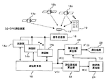
図1は、本発明の実施形態に係るGPS測位装置10の全体の構成を示した構成図である。GPS測位装置10は、GPSアンテナ17と、信号受信部18と、複数の測距部(14a,14b,14c)と、測位計算部16と、測位信頼度算出部22と、時定数算出部24と、補正位置算出部26と、を備えている。上空には複数のGPS衛星(12a,12b,12c)が配置され、時折、ビル19の壁面で反射された信号がGPSアンテナ17に入力されることもある。
FIG. 1 is a configuration diagram showing the overall configuration of a
例えば車両に搭載されたGPS測位装置10の測位計算部16は、複数のGPS衛星12からの擬似距離によって求められた位置ベクトルP(t)と、ドップラー周波数から算出された移動速度の速度ベクトルV(t)を測位信頼度算出部22に出力する。次に、測位信頼度算出部22は、信頼度S(t)を求め、時定数算出部24に出力する。時定数算出部24は時定数T(t)を補正位置算出部26に出力する。さらに、補正位置算出部26は、位置ベクトルP(t)と時定数T(t)を取得して補正されたユーザ位置P’(t)を出力する。
For example, the
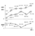
図2は、本発明の実施形態に係る速度ベクトルV(t)、位置ベクトルP(t)及び信頼度S(t)を時間軸と共に示した説明図である。ドップラー周波数は、マルチパスの影響を受けにくく、速度ベクトルV(t)は図2に示すように順調に推移するが、擬似距離から求められる位置ベクトルP(t)はP(i+3)地点で位置跳びを生じてしまい、結果として信頼度S(i+3)も低下する。 FIG. 2 is an explanatory diagram showing the velocity vector V (t), the position vector P (t), and the reliability S (t) according to the embodiment of the present invention together with the time axis. The Doppler frequency is not easily affected by multipath, and the velocity vector V (t) changes smoothly as shown in FIG. 2, but the position vector P (t) obtained from the pseudorange is located at the point P (i + 3). A jump occurs, and as a result, the reliability S (i + 3) also decreases.
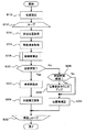
図3は、本発明の第1の実施形態に係るGPS測位装置10の補正位置算出処理の流れを示したフローチャート図である。以下、処理の流れを図3と図1を用いて説明する。処理が開始されると、使用される変数の初期設定が行われる。特に、位置安定数は、あらかじめ電源立ち上げ時、または衛星電波中断により測位できなくなった場合に初期値0にセットしておく(ステップS10)。次に、ループ開始点であるステップS12を通過して、測位位置取得(ステップS14)を実行する。
FIG. 3 is a flowchart showing the flow of the correction position calculation process of the
GPSアンテナ17よりGPS衛星からの電波が受信され、信号受信部18で復調される。得られたGPS信号は、複数の測距部14に入力される。各測距部14は、経過時間tでの各GPS衛星とユーザ位置との間に擬似的な距離R(t)及びドップラー周波数D(t)を求め、その結果を測位計算部16へ出力する。
A radio wave from a GPS satellite is received from the
測位計算部16は、前記R(t)からユーザの位置ベクトルP(t)を求め(ステップS14)、また前記D(t)からユーザの速度ベクトルV(t)を求める(ステップS16)。
The
次に、ステップS18において、得られた位置ベクトルP(t)と速度ベクトルV(t)を基にして信頼度算出を行う。 Next, in step S18, reliability is calculated based on the obtained position vector P (t) and velocity vector V (t).
1.第1の実施形態における瞬時信頼度算出
第1の実施形態は、信頼度S(t)を瞬時の位置ベクトルP(t)と速度ベクトルV(t)との比較で決定するものである。以下、第1の実施形態について説明する。
1. Calculation of instantaneous reliability in the first embodiment In the first embodiment, the reliability S (t) is determined by comparing the instantaneous position vector P (t) with the velocity vector V (t). The first embodiment will be described below.
測位計算部16は、1sec毎に各GPS衛星12の擬似距離から時刻tにおけるユーザの測位位置ベクトルP(t)={Px(t),Py(t),Pz(t)}を求める(ステップS14)。同時に、各GPS衛星12のドップラー周波数D(t)からユーザ測位速度V(t)={Vx(t),Vy(t),Vz(t)}を求める(ステップS16)。そして、この位置ベクトルP(t)と速度ベクトルV(t)を、測位信頼度算出部22、補正位置算出部26へ出力する。
The
測位信頼度算出部22は、測位計算部16から得られた位置ベクトルP(t)と速度ベクトルV(t)から、下記の(式1)により、信頼度S(t)を求める。
The positioning
S(t)=1−[√{(Px(t)−Px(t−1)−Vx(t))2+(Py(t)−Py(t−1)−Vy(t))2+(Pz(t)−Pz(t−1)−Vz(t))2}/√{Vx(t)2+Vy(t)2+Vz(t)2}] ・・・(式1) S (t) = 1− [√ {(Px (t) −Px (t−1) −Vx (t)) 2 + (Py (t) −Py (t−1) −Vy (t)) 2 + (Pz (t) −Pz (t−1) −Vz (t)) 2 } / √ {Vx (t) 2 + Vy (t) 2 + Vz (t) 2 }] (Formula 1)
ただし、√{Vx(t)2+Vy(t)2+Vz(t)2}=0のときはS(t)=0とする。そして、求めた信頼度S(t)を、時定数算出部24へ出力する(ステップS18)。 However, when √ {Vx (t) 2 + Vy (t) 2 + Vz (t) 2 } = 0, S (t) = 0. Then, the obtained reliability S (t) is output to the time constant calculation unit 24 (step S18).
ステップS20において、位置安定数が10より大きい値であるか判定する。理由は、補正するための初回位置が誤っていると、誤った位置を速度で引きずってしまい位置ずれを継続してしまう恐れがある。このため、「位置安定数>10」であれば、前回の補正位置(P’(t):いわゆる初回の補正位置)は正しい位置に測位できているものとし、時定数算出(ステップS22)に進む。 In step S20, it is determined whether the position stability number is a value greater than 10. The reason is that if the initial position for correction is incorrect, the incorrect position is dragged at a speed, and the positional deviation may continue. Therefore, if “position stability number> 10”, it is assumed that the previous correction position (P ′ (t): so-called first correction position) has been measured at the correct position, and time constant calculation (step S22) is performed. move on.
もし、位置安定数が10より小さい場合、前回の補正位置P’(t)はまだ信頼が低く、これを初回位置として補正を行うと誤った位置からの速度で延長した位置となり、誤った補正位置にしてしまう可能性があるため、速度による補正を行わないようにステップS26以下の安定化処理を行う。 If the position stability number is smaller than 10, the previous correction position P ′ (t) is still unreliable, and if this is corrected as the initial position, the position is extended at a speed from the wrong position, and the incorrect correction is made. Since there is a possibility that the position will be set, the stabilization process in step S26 and subsequent steps is performed so as not to perform the correction based on the speed.
ステップS26の安定時間経過の判断は、「T(t)<2」の場合に位置P(t)は正しいものとし、ステップS28において位置安定カウンタの「位置安定数」を1インクリメントする。これは、ステップS20の位置安定判定において、この「位置安定数>110」となったとき、例えば図2に示す速度ベクトルV(t)の走行軌跡の形状と位置ベクトルP(t)の走行軌跡の形状であったときに、この位置P(i+5))は正しいと判断するものである。次に、ステップS30では位置ベクトルの補正は行わず、P’(t)=P(t)として繰返しループ(ステップS32)へ移る。ステップS20において、正しい位置に測定できていると判定されると、ステップS22に進み、時定数算出処理を行う。 The determination of the elapse of the stabilization time in step S26 assumes that the position P (t) is correct when “T (t) <2”, and increments the “position stability number” of the position stability counter by 1 in step S28. This is because, in the position stability determination in step S20, when this “position stability number> 110”, for example, the shape of the travel locus of the speed vector V (t) and the travel locus of the position vector P (t) shown in FIG. This position P (i + 5)) is determined to be correct. Next, in step S30, the position vector is not corrected, and P ′ (t) = P (t) is set, and the process proceeds to a repeated loop (step S32). If it is determined in step S20 that the measurement has been performed at the correct position, the process proceeds to step S22 and time constant calculation processing is performed.
時定数算出部24は、測位信頼度算出部22から得られた信頼度S(t)及び位置ベクトルP(t)から、式2に代入して時定数T(t)を求める。
The time
T(t)=(1−S(t))×(T−1)+1 ・・・(式2) T (t) = (1−S (t)) × (T−1) +1 (Expression 2)
例えば、信頼度S(t)と時定数T(t)の関係を以下に示す。(例1).信頼度S(t)=1のとき、T(t)=1[sec]。(例2).信頼度S(t)=0.5のとき、T(t)=0.5×(T−1)+1→5.5[sec]。(例3).信頼度S(t)=0のとき、T(t)=T→10[sec]となる。そして、求めた時定数T(t)を、補正位置算出部26へ出力する。
For example, the relationship between the reliability S (t) and the time constant T (t) is shown below. (Example 1). When reliability S (t) = 1, T (t) = 1 [sec]. (Example 2). When the reliability S (t) = 0.5, T (t) = 0.5 × (T−1) + 1 → 5.5 [sec]. (Example 3). When the reliability S (t) = 0, T (t) = T → 10 [sec]. Then, the obtained time constant T (t) is output to the correction
次に、得られたP(t)及びV(t)を用いて補正位置P’(t)を求める。これは、マルチパスの誤差が多く信頼性が低い位置P(t)を、信頼性が高い速度V(t)を利用して時定数Tで平滑化する補正位置算出部26において、例えば下記のように補正したユーザ位置P’(t)を求める処理である(ステップS24)。
Next, a correction position P ′ (t) is obtained using the obtained P (t) and V (t). This is because, for example, in the corrected
P'(t)=W(t)×(P'(t−1)+V(t))+(1−W(t))×P(t) ・・・(式3) P ′ (t) = W (t) × (P ′ (t−1) + V (t)) + (1−W (t)) × P (t) (Equation 3)
重みW(t)は、常に0≦W(t)≦1を満たし、例えば、初回測位であるt=1のとき、W(1)=0,2≦t<Tのとき、W(t)=t−1/t,t≧Tのとき、W(t)=(T(t)−1)/T(t)となる。以下、同様にして繰返しループ(ステップS32)へ移る。 The weight W (t) always satisfies 0 ≦ W (t) ≦ 1, for example, when t = 1 as the first positioning, W (1) = 0, and 2 ≦ t <T, W (t) When t = t−1 / t, t ≧ T, W (t) = (T (t) −1) / T (t). Thereafter, the process proceeds to the repetition loop (step S32) in the same manner.
2.第2の実施形態における積算信頼度算出
次に、第2の実施形態における、積算した位置ベクトルP(t)と速度ベクトルV(t)との比較で信頼度S(t)を決定する処理について説明する。
2. Calculation of accumulated reliability in the second embodiment Next, a process for determining the reliability S (t) by comparing the accumulated position vector P (t) and the velocity vector V (t) in the second embodiment. explain.
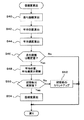
図4は、本発明の第2の実施形態に係る測位信頼度計算処理の流れを示したフローチャート図である。第1の実施形態に示した瞬時の比較では、高周波数のノイズの影響により、位置ベクトルP(t)と速度ベクトルV(t)の両者が変動し、判断が困難になることがある。測位信頼度算出部22は、図4に示すように、規定距離を走行する毎に信頼度S(t)を決定する方法がある。
FIG. 4 is a flowchart showing the flow of the positioning reliability calculation process according to the second embodiment of the present invention. In the instantaneous comparison shown in the first embodiment, the position vector P (t) and the velocity vector V (t) may both fluctuate due to the influence of high-frequency noise, and determination may be difficult. As shown in FIG. 4, the positioning
まず、走行距離L、カウンタn、平均位置R[4]及び記憶数Mの初期値は0とする。 First, the initial values of the travel distance L, the counter n, the average position R [4], and the stored number M are set to zero.
ステップS40の走行距離算出において、V(t)から走行距離L=L+√(Vx(t)2+Vy(t)2+Vz(t)2)を算出し、P(t)から平均位置R[4]=ΣP(t)/n(ステップS42)及びV(t)から平均速度H[4]=ΣV(t)/n(ステップS44)を計算する。ここで、R[k],H[k](k=0,1,2,3,4)は、これまでに、走行距離Lを走行する毎に、メモリに記憶した平均位置、平均速度であり、k=0は最も過去のものとなる。 In the travel distance calculation of step S40, the travel distance L = L + √ (Vx (t) 2 + Vy (t) 2 + Vz (t) 2 ) is calculated from V (t) and the average position R [4 ] = ΣP (t) / n (step S42) and average speed H [4] = ΣV (t) / n (step S44) are calculated from V (t). Here, R [k], H [k] (k = 0, 1, 2, 3, 4) are average positions and average speeds stored in the memory every time the travel distance L is traveled. Yes, k = 0 is the oldest.
これは、ステップS46における走行距離判定において、走行距離がL≧10mのときステップS48における平均位置、平均速度の更新を実施して、過去の平均位置R[0]、平均速度H[0]を更新する。 In the travel distance determination in step S46, when the travel distance is L ≧ 10 m, the average position and average speed in step S48 are updated, and the past average position R [0] and average speed H [0] are obtained. Update.
ステップS50における記憶数判定において、Mは、走行距離が10m間隔毎に過去の平均位置、平均速度を記憶した記憶数であり、M≧3のとき、信頼度算出(ステップS54)を実施する。そうでない場合は、まだ過去の記憶数が不足しているものとし、記憶数のカウントアップ(ステップS52)で記憶数Mを1インクリメントして終了する。 In the determination of the number of memories in step S50, M is the number of memories storing the past average position and average speed for every 10 m of travel distance. When M ≧ 3, reliability calculation (step S54) is performed. Otherwise, it is assumed that the past number of memories is still insufficient, and the number of memories M is incremented by 1 (step S52), and the process is terminated.
さらに、ステップS52において、(式4)に代入して過去3つの記憶したR[k],H[k]からS(t)を計算する。

3.第3の実施形態における積算信頼度算出
次に、第3の実施形態における、記憶した平均データの中で過去のものよりも最新のものを重視する処理について説明する。
3. Calculation of integrated reliability in the third embodiment Next, processing in the third embodiment that places importance on the latest data rather than the past data in the stored average data will be described.
図4のステップS54を、(式5)に変更することにより、過去データよりも現在のものを重視することもできる。
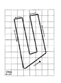
図5は、本発明の実施形態に係るGPS測位装置10による走行試験で用いた道路図である。本走行試験を行った道路は、マルチパスの影響が非常に大きい環境であり、1方、2方、4方を高層ビルに囲まれた地区を含んでいる。
FIG. 5 is a road diagram used in a running test by the
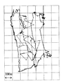
図6は、本発明の参考となる位置補正がない場合の測位結果を示す軌跡図である。位置補正が無い場合は、マルチパスの影響により正しい走行ルートの軌跡が全く示されず、頻繁に位置跳びが発生している。 FIG. 6 is a trajectory diagram showing a positioning result when there is no position correction which is a reference of the present invention. When there is no position correction, the trajectory of a correct travel route is not shown at all due to the influence of multipath, and position jumps frequently occur.
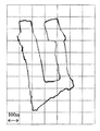
図7は、本発明の実施形態に係るGPS測位装置を用いて、位置補正処理をおこなった場合の軌跡図である。本実施形態では、マルチパスの影響を低減しつつほぼ正しい走行ルートの軌跡を残すことができている。以上のことから、本実施形態に係るGPS測位装置は、位置補正処理によりマルチパスの影響が大きく測位精度が非常に悪い環境でも十分に機能することが可能である。 FIG. 7 is a trajectory diagram when position correction processing is performed using the GPS positioning device according to the embodiment of the present invention. In the present embodiment, a substantially correct trajectory of the travel route can be left while reducing the influence of multipath. From the above, the GPS positioning apparatus according to the present embodiment can sufficiently function even in an environment where the influence of multipath is large and the positioning accuracy is very poor due to the position correction process.
10 GPS測位装置、12 GPS衛星、14 測距部、16 測位計算部、17 GPSアンテナ、18 信号受信部、19 ビル、22 測位信頼度算出部、24 時定数算出部、26 補正位置算出部。
DESCRIPTION OF
Claims (7)
衛星から受信機までの擬似距離を算出する擬似距離算出手段と、
複数の擬似距離から受信機の位置情報を算出する測位算出手段と、
キャリアのドップラー周波数から受信機の移動速度を算出する移動速度算出手段と、
算出された受信機の位置情報と移動速度の相関値を位置情報の信頼度として算出する測位信頼度算出手段と、
算出された信頼度と反比例関係となる時定数を、位置変化の時定数として算出する時定数算出手段と、
時定数算出手段からの時定数により、測位算出手段からの位置情報を補正する補正位置算出手段と、
を有することを特徴とする測位装置。 A receiver mounted on a mobile body for receiving signals from a plurality of satellites, and positioning means for detecting a code pseudorange used for positioning, a carrier Doppler frequency, and the like from the received signals to determine the position of the receiver; In a positioning device having
A pseudo distance calculating means for calculating a pseudo distance from the satellite to the receiver;
Positioning calculation means for calculating position information of the receiver from a plurality of pseudo-ranges;
A moving speed calculating means for calculating the moving speed of the receiver from the carrier Doppler frequency;
A positioning reliability calculation means for calculating a correlation value between the calculated position information of the receiver and the moving speed as a reliability of the position information;
A time constant calculating means for calculating a time constant that is inversely proportional to the calculated reliability as a time constant of the position change;
A correction position calculation means for correcting position information from the positioning calculation means based on a time constant from the time constant calculation means;
A positioning device comprising:
測位信頼度算出手段は、
算出された受信機の位置情報と移動速度を用いて、一定距離毎に走行した位置と移動速度の軌跡から相関値を求め、位置情報の信頼度として算出することを特徴とする測位装置。 The positioning device according to claim 1,
The positioning reliability calculation means is
A positioning apparatus characterized in that, using the calculated position information and moving speed of the receiver, a correlation value is obtained from a position traveled at a fixed distance and a trajectory of moving speed, and calculated as reliability of the position information.
さらに、移動速度算出手段からの移動速度を積算して積算速度を算出する積算速度算出手段を有し、
積算速度算出手段は、時定数算出手段からの時定数により位置と積算速度との差分となるオフセットを平滑化することを特徴とする測位装置。 The positioning device according to claim 1 or 2,
Furthermore, it has integrated speed calculating means for calculating the integrated speed by integrating the moving speed from the moving speed calculating means,
The integrated speed calculating means smoothes an offset that is a difference between the position and the integrated speed by the time constant from the time constant calculating means.
測位信頼度算出手段は、
移動体の運動状態を測定するセンサなどから得られた移動速度と、測位算出手段からの位置情報と、の相関値を位置情報の信頼度として算出することを特徴とする測位装置。 The positioning device according to any one of claims 1 to 3,
The positioning reliability calculation means is
A positioning apparatus that calculates a correlation value between a moving speed obtained from a sensor or the like for measuring a motion state of a moving body and position information from a positioning calculation means as reliability of position information.
衛星から受信機までの擬似距離を算出する擬似距離算出工程と、
複数の擬似距離から受信機の位置情報を算出する測位算出工程と、
キャリアのドップラー周波数から受信機の移動速度を算出する移動速度算出工程と、
算出された受信機の位置情報と移動速度の相関値を位置情報の信頼度として算出する測位信頼度算出工程と、
算出された信頼度と反比例関係となる時定数を、位置変化の時定数として算出する時定数算出工程と、
時定数算出工程からの時定数により、測位算出工程からの位置情報を補正する補正位置算出工程と、
を含むことを特徴とする測位方法。 In the positioning method of receiving signals from a plurality of satellites by a receiver and detecting the code pseudorange and carrier Doppler frequency used for positioning from the received signals to determine the position of the receiver,
A pseudo-range calculating step for calculating a pseudo-range from the satellite to the receiver;
A positioning calculation step for calculating position information of the receiver from a plurality of pseudo-ranges;
A moving speed calculating step of calculating the moving speed of the receiver from the carrier Doppler frequency;
A positioning reliability calculation step of calculating a correlation value between the calculated position information of the receiver and the moving speed as the reliability of the position information;
A time constant calculating step of calculating a time constant that is inversely proportional to the calculated reliability as a time constant of the position change;
A correction position calculation step for correcting the position information from the positioning calculation step by the time constant from the time constant calculation step;
A positioning method comprising:
測位信頼度算出工程は、
算出された受信機の位置情報と移動速度を用いて、一定距離毎に走行した位置と移動速度の軌跡から相関値を求め、位置情報の信頼度として算出することを特徴とする測位方法。 The positioning method according to claim 5, wherein
The positioning reliability calculation process
A positioning method characterized in that, using the calculated position information and moving speed of the receiver, a correlation value is obtained from a locus of moving at a certain distance and a trajectory of moving speed, and calculated as reliability of the position information.
さらに、移動速度算出工程からの移動速度を積算して積算速度を算出する積算速度算出工程を有し、
積算速度算出工程は、時定数算出工程からの時定数により位置と積算速度との差分となるオフセットを平滑化することを特徴とする測位方法。
In the positioning method according to claim 5 or 6,
Furthermore, it has an integrated speed calculating step of calculating the integrated speed by integrating the moving speed from the moving speed calculating step,
The integrated speed calculating step smoothes an offset that is a difference between the position and the integrated speed based on the time constant from the time constant calculating step.
Priority Applications (1)
| Application Number | Priority Date | Filing Date | Title |
|---|---|---|---|
| JP2005193625A JP2007010554A (en) | 2005-07-01 | 2005-07-01 | Positioning device |
Applications Claiming Priority (1)
| Application Number | Priority Date | Filing Date | Title |
|---|---|---|---|
| JP2005193625A JP2007010554A (en) | 2005-07-01 | 2005-07-01 | Positioning device |
Publications (1)
| Publication Number | Publication Date |
|---|---|
| JP2007010554A true JP2007010554A (en) | 2007-01-18 |
Family
ID=37749259
Family Applications (1)
| Application Number | Title | Priority Date | Filing Date |
|---|---|---|---|
| JP2005193625A Pending JP2007010554A (en) | 2005-07-01 | 2005-07-01 | Positioning device |
Country Status (1)
| Country | Link |
|---|---|
| JP (1) | JP2007010554A (en) |
Cited By (5)
| Publication number | Priority date | Publication date | Assignee | Title |
|---|---|---|---|---|
| JP2009128055A (en) * | 2007-11-20 | 2009-06-11 | Furuno Electric Co Ltd | Abnormal satellite detector and positioning apparatus |
| JP2010145179A (en) * | 2008-12-17 | 2010-07-01 | Toyota Motor Corp | Gnss receiving device and positioning method |
| JP2012127899A (en) * | 2010-12-17 | 2012-07-05 | Isuzu Motors Ltd | Positioning accuracy determining device |
| CN115951174A (en) * | 2023-03-14 | 2023-04-11 | 湖南湘能电气自动化有限公司 | Traveling wave ranging network correction method and system based on power grid abnormal credible area identification |
| WO2023062782A1 (en) * | 2021-10-14 | 2023-04-20 | パイオニア株式会社 | Information processing apparatus, control method, program, and storage medium |
Citations (7)
| Publication number | Priority date | Publication date | Assignee | Title |
|---|---|---|---|---|
| JPH07198821A (en) * | 1994-01-06 | 1995-08-01 | Japan Radio Co Ltd | Gps receivr and its positoning method |
| JPH095417A (en) * | 1995-06-22 | 1997-01-10 | Matsushita Electric Ind Co Ltd | Gps receiving device |
| JP2000193733A (en) * | 1998-12-25 | 2000-07-14 | Japan Radio Co Ltd | Determining device and method |
| JP2001124840A (en) * | 1999-10-28 | 2001-05-11 | Matsushita Electric Ind Co Ltd | Gps receiver and positioning method |
| JP2002323551A (en) * | 2001-04-27 | 2002-11-08 | Fujitsu Ten Ltd | Navigation apparatus |
| JP2005077114A (en) * | 2003-08-29 | 2005-03-24 | Pioneer Electronic Corp | Multipath detector, multipath detection method, navigation system, and computer program |
| JP2006064593A (en) * | 2004-08-27 | 2006-03-09 | Japan Radio Co Ltd | Positioning device |
-
2005
- 2005-07-01 JP JP2005193625A patent/JP2007010554A/en active Pending
Patent Citations (7)
| Publication number | Priority date | Publication date | Assignee | Title |
|---|---|---|---|---|
| JPH07198821A (en) * | 1994-01-06 | 1995-08-01 | Japan Radio Co Ltd | Gps receivr and its positoning method |
| JPH095417A (en) * | 1995-06-22 | 1997-01-10 | Matsushita Electric Ind Co Ltd | Gps receiving device |
| JP2000193733A (en) * | 1998-12-25 | 2000-07-14 | Japan Radio Co Ltd | Determining device and method |
| JP2001124840A (en) * | 1999-10-28 | 2001-05-11 | Matsushita Electric Ind Co Ltd | Gps receiver and positioning method |
| JP2002323551A (en) * | 2001-04-27 | 2002-11-08 | Fujitsu Ten Ltd | Navigation apparatus |
| JP2005077114A (en) * | 2003-08-29 | 2005-03-24 | Pioneer Electronic Corp | Multipath detector, multipath detection method, navigation system, and computer program |
| JP2006064593A (en) * | 2004-08-27 | 2006-03-09 | Japan Radio Co Ltd | Positioning device |
Cited By (5)
| Publication number | Priority date | Publication date | Assignee | Title |
|---|---|---|---|---|
| JP2009128055A (en) * | 2007-11-20 | 2009-06-11 | Furuno Electric Co Ltd | Abnormal satellite detector and positioning apparatus |
| JP2010145179A (en) * | 2008-12-17 | 2010-07-01 | Toyota Motor Corp | Gnss receiving device and positioning method |
| JP2012127899A (en) * | 2010-12-17 | 2012-07-05 | Isuzu Motors Ltd | Positioning accuracy determining device |
| WO2023062782A1 (en) * | 2021-10-14 | 2023-04-20 | パイオニア株式会社 | Information processing apparatus, control method, program, and storage medium |
| CN115951174A (en) * | 2023-03-14 | 2023-04-11 | 湖南湘能电气自动化有限公司 | Traveling wave ranging network correction method and system based on power grid abnormal credible area identification |
Similar Documents
| Publication | Publication Date | Title |
|---|---|---|
| US11441907B2 (en) | Positioning device and positioning method | |
| EP2400270B1 (en) | Track information generating device, track information generating method, and computer-readable storage medium | |
| US7987047B2 (en) | Navigation equipment | |
| CN110914711B (en) | Positioning device | |
| US6574557B2 (en) | Positioning error range setting apparatus, method, and navigation apparatus | |
| WO2014002211A1 (en) | Positioning device | |
| US9423486B2 (en) | Position calculating method and position calculating device | |
| WO2014125754A1 (en) | Vehicle-path computation method | |
| WO2014125769A1 (en) | Vehicle-orientation detection method and vehicle-orientation detection device | |
| JP2005300167A (en) | Satellite positioning system, and navigation system | |
| WO2016203744A1 (en) | Positioning device | |
| JP4905054B2 (en) | Mobile satellite radio receiver | |
| JPH0868651A (en) | Current position detector for vehicle | |
| EP1256813A2 (en) | Apparatus and method for navigation and positioning | |
| JP2017167053A (en) | Vehicle location determination device | |
| JP2007010554A (en) | Positioning device | |
| JP2008051572A (en) | Navigation apparatus, method therefor, and program therefor | |
| JP2008051573A (en) | Navigation apparatus, method therefor, and program therefor | |
| RU2202102C2 (en) | Procedure establishing positions of mobile objects and device for its realization | |
| JP2010145178A (en) | Moving body position specification device | |
| JP2010112759A (en) | Mobile body positioning apparatus | |
| JP2007010550A (en) | Positioning device and positioning method | |
| JP3827598B2 (en) | Moving body position measurement system | |
| JP2000180191A (en) | Navigator | |
| JP2008180598A (en) | Device for positioning mobile body |
Legal Events
| Date | Code | Title | Description |
|---|---|---|---|
| A621 | Written request for application examination |
Free format text: JAPANESE INTERMEDIATE CODE: A621 Effective date: 20080625 |
|
| A977 | Report on retrieval |
Free format text: JAPANESE INTERMEDIATE CODE: A971007 Effective date: 20101209 |
|
| A131 | Notification of reasons for refusal |
Effective date: 20101214 Free format text: JAPANESE INTERMEDIATE CODE: A131 |
|
| A521 | Written amendment |
Free format text: JAPANESE INTERMEDIATE CODE: A523 Effective date: 20110210 |
|
| A131 | Notification of reasons for refusal |
Free format text: JAPANESE INTERMEDIATE CODE: A131 Effective date: 20110705 |
|
| A02 | Decision of refusal |
Effective date: 20111206 Free format text: JAPANESE INTERMEDIATE CODE: A02 |