JP2007004059A - Endoscopic apparatus - Google Patents
Endoscopic apparatus Download PDFInfo
- Publication number
- JP2007004059A JP2007004059A JP2005186974A JP2005186974A JP2007004059A JP 2007004059 A JP2007004059 A JP 2007004059A JP 2005186974 A JP2005186974 A JP 2005186974A JP 2005186974 A JP2005186974 A JP 2005186974A JP 2007004059 A JP2007004059 A JP 2007004059A
- Authority
- JP
- Japan
- Prior art keywords
- bending
- drive amount
- amount
- drive
- instruction
- Prior art date
- Legal status (The legal status is an assumption and is not a legal conclusion. Google has not performed a legal analysis and makes no representation as to the accuracy of the status listed.)
- Pending
Links
Images


Abstract
Description
本発明は、主に工業用内視鏡分野で使用され、パイプ等の被検体の内部に挿入され、その内部を観察する内視鏡装置に関する。 The present invention relates to an endoscope apparatus that is mainly used in the field of industrial endoscopes, is inserted into a subject such as a pipe, and observes the inside thereof.
近年、細長の挿入部を挿入することにより、被検体内を観察することができる内視鏡は広く用いられるようになった。このような内視鏡においては、屈曲した部位に挿入できるように湾曲部を設けられている。
また、湾曲部を簡単に湾曲できるように電動駆動機構を設け、湾曲指示に従って電動湾曲機構により湾曲部を電動駆動できるようにした電動湾曲内視鏡がある。
例えば、第1の従来例として特開2002−323661号公報には、電動湾曲内視鏡において、狭い空間でも内視鏡先端を挿入部に対して直線化するセンタリング機能が設けてある。この機能により直線化する作業を一操作で完了させることが可能となる。
また、第2の従来例として特許第2948925号公報の内視鏡装置には、内視鏡の挿入部を駆動する駆動手段を有する内視鏡装置において、内視鏡先端の撮像手段から出力される映像信号と、挿入部駆動手段、挿入部回転駆動手段、湾曲駆動手段のうち少なくとも1つの駆動指示手段から出力される指示信号を表示手段に表示し、作業者が如何なる状況でどのような駆動手段を操作したのかを明らかにすることを特徴とする。
There is also an electric bending endoscope in which an electric drive mechanism is provided so that the bending portion can be bent easily, and the bending portion can be electrically driven by the electric bending mechanism in accordance with a bending instruction.
For example, as a first conventional example, Japanese Patent Application Laid-Open No. 2002-323661 provides a centering function that linearizes the endoscope tip with respect to the insertion portion even in a narrow space in an electric bending endoscope. This function makes it possible to complete the straightening operation in one operation.
In addition, in the endoscope apparatus disclosed in Japanese Patent No. 2948925 as a second conventional example, an endoscope apparatus having a driving means for driving an insertion portion of the endoscope is output from the imaging means at the distal end of the endoscope. And an instruction signal output from at least one drive instruction means among the insertion portion drive means, the insertion portion rotation drive means, and the bending drive means are displayed on the display means. It is characterized by clarifying whether the means has been operated.
しかしながら、上述した第1及び第2の従来例では、以下の問題点がある。実際に内視鏡により検査する場合、内視鏡先端の湾曲部の湾曲動作を考えると、ユーザはジョイスティックのような湾曲指示手段により湾曲部を湾曲させながら観察を行う。
つまり、ある第1の特定観察部位に湾曲部を湾曲させて観察するだけでなく、第1の特定観察部位以外の箇所に湾曲部を湾曲させて観察するといった作業が繰り返し行われている中で、第1の特定観察部位を再び観察したくなることが度々発生する。
この場合、再度第1の特定観察部位に向くように湾曲指示手段で湾曲部に湾曲をかけるといった探索をすることとなる。しかしながら、簡単な操作で湾曲位置を変えられる電動湾曲の機能上、再び戻りたい第1の特定観察部位が何処であったのかユーザの記憶を頼りに探索する場合、通常ユーザの記憶に残っていないことが多く、この探索に時間を要してしまうという問題があった。
また、内視鏡挿入部の挿入量に関してはユーザが湾曲をかけ観察しながら挿入してくことから、第1の特定観察部位を再び観察する場合、湾曲指示手段で再度湾曲指示をしながら観察部位を探索し、さらに挿入部の挿入量もユーザの記憶を頼りに操作することになり、この探索に時間を要するという問題がある。
However, the first and second conventional examples described above have the following problems. When actually inspecting with an endoscope, considering the bending operation of the bending portion at the distal end of the endoscope, the user observes the bending portion with a bending instruction means such as a joystick.
That is, not only the curved portion is observed at a certain first specific observation site but also the observation is performed by bending the curved portion at a location other than the first specific observation site. Often, the user wants to observe the first specific observation site again.
In this case, a search is made such that the bending portion is bent by the bending instruction means so as to be directed again to the first specific observation site. However, when searching based on the user's memory for the location of the first specific observation site to be returned again on the function of electric bending that can change the bending position with a simple operation, it is not normally stored in the user's memory. In many cases, this search takes time.
In addition, since the user inserts the endoscope insertion portion while curving and observing, when observing the first specific observation portion again, the observation portion is again instructed to bend by the bending instruction means. In addition, the amount of insertion in the insertion portion is also operated depending on the user's memory, and there is a problem that this search takes time.
(発明の目的)
本発明は上述した点に鑑みてなされたもので、以前に設定した観察部位を観察できる湾曲状態に簡単に設定できる内視鏡装置を提供することを目的とする。
また、本発明は、以前に設定した観察部位を観察できる湾曲状態に簡単に再生できる他に、挿入部の挿入位置の再生も可能にして内視鏡による観察を効率良くできる内視鏡装置を提供することを目的とする。
(Object of invention)
The present invention has been made in view of the above-described points, and an object thereof is to provide an endoscope apparatus that can be easily set to a curved state in which a previously set observation site can be observed.
Further, the present invention provides an endoscope apparatus that can efficiently reproduce an insertion position of an insertion portion and can efficiently reproduce an insertion position of an insertion portion, in addition to being able to easily reproduce a curved state in which a previously set observation site can be observed. The purpose is to provide.
本発明の内視鏡装置は、内視鏡に設けられた湾曲部と、
前記湾曲部を電気的に湾曲駆動する湾曲駆動手段と、
前記湾曲部の湾曲指示をする湾曲指示手段と、
前記湾曲駆動手段による湾曲駆動量を検出する湾曲駆動量検出手段と、
前記湾曲駆動量検出手段の湾曲状態を記憶指示する湾曲駆動量記憶指示手段と、
前記湾曲駆動量記憶指示手段の記憶指示に応じ、前記湾曲駆動量検出手段が検出した前記湾曲量に対応する検出量を記憶する湾曲駆動量記憶手段と、
前記湾曲駆動量記憶手段で記憶された前記検出量の再生指示する湾曲駆動量再生指示手段と、
前記湾曲駆動量再生指示手段の再生指示に応じ、前記湾曲駆動量記憶手段で記憶された湾曲駆動量を再生し、前記湾曲部を前記湾曲駆動量の状態に湾曲駆動させる制御手段と、 を具備したことを特徴とする。
上記構成により、湾曲駆動量再生指示手段を再生指示することにより、湾曲駆動量記憶手段で記憶された湾曲駆動量の状態、つまり以前の湾曲状態に簡単に設定することができるようにしている。
An endoscope apparatus according to the present invention includes a bending portion provided in an endoscope,
A bending drive means for electrically bending the bending portion;
Bending instruction means for instructing bending of the bending portion;
A bending drive amount detection means for detecting a bending drive amount by the bending drive means;
Bending drive amount storage instruction means for storing and instructing the bending state of the bending drive amount detection means;
Bending drive amount storage means for storing a detection amount corresponding to the bending amount detected by the bending drive amount detection means in response to a storage instruction of the bending drive amount storage instruction means;
A bending drive amount reproduction instruction means for instructing reproduction of the detected amount stored in the bending drive amount storage means;
Control means for reproducing the bending drive amount stored in the bending drive amount storage means in response to a reproduction instruction from the bending drive amount reproduction instruction means and driving the bending portion to bend to the bending drive amount state. It is characterized by that.
With the above-described configuration, by instructing the bending drive amount reproduction instruction unit to reproduce, the state of the bending drive amount stored in the bending drive amount storage unit, that is, the previous bending state can be easily set.
本発明によれば、湾曲駆動量再生指示手段の再生指示により、以前に設定した湾曲状態に簡単に設定することができる。 According to the present invention, the previously set bending state can be easily set by the reproduction instruction of the bending drive amount reproduction instruction means.
以下、図面を参照して本発明の実施例を説明する。 Embodiments of the present invention will be described below with reference to the drawings.
図1及び図2は本発明の実施例1に係り、図1は本発明の実施例1の内視鏡装置の全体構成を示し、図2は本実施例の動作内容を示す。
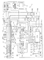
図1に示すように本発明の実施例1の内視鏡装置1は、パイプ等の被検体内に挿入される電動湾曲内視鏡(以下では単に内視鏡と略記)2と、この内視鏡2が接続され、この内視鏡に内蔵された撮像手段に対して信号処理を行うカメラコントロールユニット(以下、CCUと略記)3と、このCCUによる生成された映像信号が入力され、この映像信号に対応する内視鏡画像を表示するモニタ4と、前記CCU3からの映像信号が入力され、前記映像信号を記録する例えばDVD記録装置等の画像記録装置5とを有する。
内視鏡2は、被検体内に挿入される細長で軟性の挿入部6を有し、この挿入部6は、その先端に硬質の先端部11が設けられ、この先端部11の後端には湾曲自在の湾曲部12が設けられている。また、この湾曲部12の後端から手元側までは、柔軟性のある軟性部13が形成されている。
1 and 2 relate to
As shown in FIG. 1, an
The
この挿入部6の先端部11には、照明窓と観察窓(撮像窓)とが設けてあり、照明窓には、例えば照明レンズと一体化された発光ダイオード(LEDと略記)14が取り付けられている。このLED14は、LED駆動回路15を介して所定の駆動電力により発光駆動される。
また、観察窓には、その観察視野内の被検体の光学像を結ぶ対物レンズ16が取り付けられ、その結像位置には撮像素子として例えば電荷結合素子(CCDと略記)17が配置されている。このCCD17は、挿入部6内を挿通された信号線を介してCCU3と接続される。
CCU3は、CCD17にCCD駆動信号を印加するCCD駆動回路18と、CCD駆動信号の印加によりCCD17から出力される撮像信号に対する信号処理を行う信号処理回路19とを有する。
The
In addition, an
The
この信号処理回路19により信号処理されて生成された標準的な映像信号は、モニタ4に出力され、モニタ4の表示面にはCCD17で撮像した画像が内視鏡画像として表示される。
また、挿入部6内には、観察視野の上、下方向に沿ってそれぞれ挿通され、観察視野の上、下方向にそれぞれ湾曲させるためのUPアングルワイヤ21Uと、DOWNアングルワイヤ21Dが設けてある。UPアングルワイヤ21U及びDOWNアングルワイヤ21Dの先端は、湾曲部12を構成する複数の湾曲駒の最先端の湾曲駒、或いは最先端の湾曲駒が回動自在に連結された先端部11に固着されている。
また、挿入部6内には、観察視野の左、右方向に沿ってそれぞれ挿通され、観察視野の左、右方向にそれぞれ湾曲させるためのLEFTアングルワイヤ21Lと、RIGHTアングルワイヤ21Rが設けてある。LEFTアングルワイヤ21L及びRIGHTアングルワイヤ21Rの先端は、湾曲部12を構成する最先端の湾曲駒、先端部11に固着されている。
A standard video signal generated by signal processing by the
Further, an
Further, a
UPアングルワイヤ21U及びDOWNアングルワイヤ21Dの後端は、挿入部6の後端から後方側に延出され、例えば操作部内に配置された電動湾曲駆動機構部22における上下方向の電気的な湾曲駆動手段としてのU/Dモータ23Aの回転軸に回動自在に取り付けたプーリ24Aに掛け渡すようにして連結されている。
また、LEFTアングルワイヤ21L及びRIGHTアングルワイヤ21Rの後端は、電動湾曲駆動機構部22における左右方向の電気的な湾曲駆動手段としてのL/Rモータ23Bの回転軸に回動自在に取り付けたプーリ24Bに掛け渡すようにして連結されている。
また、U/Dモータ23Aには、その回転軸に上下方向の湾曲駆動量検出手段としてのU/Dポテンショメータ25Aが、L/Rモータ23Bには、その回転軸に左右方向の湾曲駆動量検出手段としてのL/Rにポテンショメータ25Bがそれぞれ接続され、それぞれの回転角(或いは回転量)を検出することができるようにしている。
The rear ends of the
Further, the rear ends of the
Further, the U /
なお、これらの回転角は、湾曲部12の湾曲駆動量に対応する。また、複数の方向の湾曲駆動量を検出することにより、湾曲方向の情報も検出する。そして、後述するようにU/Dポテンショメータ25A及びL/Rにポテンショメータ25Bによる検出量を記憶することにより、湾曲方向を含む湾曲駆動量、つまり湾曲部12の湾曲状態を記憶することができる。
また、U/Dモータ23A及びL/Rモータ23B、制御回路26に設けてある駆動部27と接続され、この駆動部27からモータ駆動信号を印加することにより、正方向に回転させたり、この正方向と逆方向に回転駆動できるようにしている。
例えばU/Dモータ23Aを図1の矢印で示すように回転させることにより、UPアングルワイヤ21Uを牽引し、かつ他方のDOWNアングルワイヤ21Dを弛緩させることにより、湾曲部12を上方向に湾曲させることができる。
Note that these rotation angles correspond to the bending drive amount of the
The U /
For example, the U /
上記駆動部27は、制御回路26に設けたD/A変換器28を介して湾曲に関する全体の制御を行うCPU29と接続されている。また、このCPU29には、A/D変換器30を介してポテンショメータ25A、25Bと接続され、U/Dモータ23A及びL/Rモータ23Bの回転角の検出信号が入力される。
また、この制御回路26には、湾曲部12の(湾曲方向を含む)湾曲駆動量の湾曲指示を行う湾曲指示手段としての例えばジョイスティック31が設けてある。このジョイスティック31の基端は、ジョイスティック出力部32に接続され、ユーザはこのジョイスティック31を、上下、左右等、任意の方向に傾動する湾曲指示を行うことにより、その傾動に対応した湾曲指示信号としてのジョイスティック出力信号が、ジョイスティック出力部32から出力される。このジョイスティック出力信号は、A/D変換器33によりデジタル信号に変換されてCPU29に入力される。
そして、CPU29は、ユーザによるジョイスティック31の湾曲指示に対応して、D/A変換器28、駆動部27を介してU/Dモータ23A及びL/Rモータ23Bの回転を制御する。また、その際に、U/Dポテンショメータ25A及びL/Rにポテンショメータ25Bによる検出量を参照する。
The
In addition, the
Then, the
また、このCPU29は、湾曲駆動量を記憶指示する湾曲記憶スイッチ34と、その湾曲駆動量を再生指示する湾曲再生スイッチ35及び図示しない他の機能スイッチが接続されている。
また、このCPU29には、湾曲部12の湾曲状態、或いは湾曲駆動量の記憶手段として例えばSDRAM36が接続されており、SDRAM36は、湾曲記憶スイッチ34により記憶指示された時のU/Dポテンショメータ25A及びL/Rにポテンショメータ25Bにより検出されている湾曲状態に対応する湾曲駆動量を記憶する。また、SDRAM36は、湾曲再生スイッチ35による再生指示が行われると、記憶されている湾曲駆動量が読み出され、湾曲記憶スイッチ34の記憶指示時の湾曲状態の再生に利用される。
次に図2を参照して本実施例による代表的な動作を説明する。
図1に示すように設定した後、図示しない電源スイッチをONにする操作を行い、内視鏡装置1の各部に電源が供給されるようになり、図2のステップS1に示すように内視鏡2の挿入部6をパイプ等の被検体内に挿入して内視鏡検査が開始する。
Further, the
Further, for example, an
Next, a typical operation according to the present embodiment will be described with reference to FIG.
After setting as shown in FIG. 1, an operation to turn on a power switch (not shown) is performed to supply power to each part of the
被検体内は、LED駆動回路15からの駆動電源により発光するLED14により照明され、照明された部位は対物レンズ16によりCCD17に結像され、このCCD17により撮像された画像がモニタ4に表示される。
また、CPU29は、ステップS2に示すようにジョイスティック31による湾曲指示の操作入力に応じて、湾曲部12の湾曲駆動の制御を行う。ユーザは、モニタ4に表示される画像を観察しながら、ジョイスティック31で湾曲指示することにより、湾曲部12を所望とする方向に湾曲させる等して、被検体の内部を観察することができる。
例えば上方向を観察することを望む場合には、ユーザはジョイスティック31を上方向に傾ける。その湾曲指示の操作により、ジョイスティック出力部32から対応するジョイスティック出力信号がA/D変換器33に出力され、デジタル信号に変換されてCPU29に入力される。CPU29は、この入力に対応した制御信号をD/A変換器28を介して駆動部27に出力する。
The inside of the subject is illuminated by the
Further, the
For example, when it is desired to observe the upward direction, the user tilts the
そして、駆動部27は、ジョイスティック31の上方向への傾動による湾曲指示に対応して、U/Dモータ23Aを回転させて、湾曲部12を上方向に湾曲させる。この場合、ジョイスティック31を上方向に傾けた角度に対応した量だけ、湾曲部12を上方向に湾曲させる。そして、CPU29は、ステップS3に示すように、ユーザによる湾曲記憶スイッチ34の記憶指示の信号を監視する。
ユーザは、ジョイスティック31を傾けて湾曲部12を湾曲させながら、被検体の内部を観察する作業を行う。そして、例えば留意すべき部位を観察視野に捉えたような場合のように、後でその観察視野の状態に設定することを望む可能性があるような場合には、湾曲記憶スイッチ34で記憶指示をする。
CPU29は、湾曲記憶スイッチ34の記憶指示の操作がされていない場合には、ステップS2の処理に戻り、湾曲記憶スイッチ34が操作された場合には、ステップS4に示すようにその湾曲記憶スイッチ34が操作された場合における湾曲部12の湾曲駆動量、つまり湾曲部12の湾曲状態に対応し、湾曲量検出手段としてのポテンショメータ25A、25Bにより検出されている湾曲駆動量のデータをSDRAM36に記憶させる。
Then, the driving
The user performs an operation of observing the inside of the subject while tilting the
The
つまり、湾曲部12の湾曲状態に対応する湾曲駆動量の値は、ポテンショメータ25A、25Bにより検出量として常時検出され、検出された検出量はA/D変換器30を介してCPU29に一定間隔で順次入力されている。そして、CPU29は、湾曲記憶スイッチ34の記憶指示がされた時、このCPU29にポテンショメータ25A、25BからA/D変換器30を介して入力されている検出量(つまり湾曲駆動量)のデータをSDRAM36に記憶する。
また、CPU29は、ステップS5に示すように湾曲再生スイッチ35の再生指示の入力を監視している。そして、ユーザが、この湾曲再生スイッチ35の再生指示を行わない場合には、ステップS2に戻る。
一方、この湾曲再生スイッチ35の再生指示が行われた場合には、ステップS6に示すようにCPU29は、SDRAM36に記憶されている検出量、つまり湾曲駆動量のデータを読み出す。さらに、ステップS7に示すようにCPU29は、このSDRAM36から読み出した湾曲駆動量のデータを湾曲指示とみなしてA/D変換器28、駆動部27を介してU/Dモータ23A或いはL/Rモータ23Bを回転駆動させる。
That is, the value of the bending drive amount corresponding to the bending state of the bending
Further, the
On the other hand, when an instruction to reproduce the
そして、湾曲部12を上記湾曲記憶スイッチ34が記憶指示された時の湾曲状態に設定する。従って、湾曲再生スイッチ35で再生指示する操作をすることにより、ユーザが湾曲記憶スイッチ34を操作した時の湾曲部12の湾曲状態に速やかに設定することができるようになる。
ステップS6による設定の処理が終了すると、ステップS2に戻り、ステップS2からステップS7の処理が順次繰り返される。
このような動作を行う本実施例によれば、湾曲記憶スイッチ34で記憶指示した場合にその時の湾曲状態の湾曲駆動量の情報が記憶され、湾曲再生スイッチ35で再生指示された場合には湾曲記憶スイッチ34が記憶指示された場合の湾曲状態に速やかに設定できるようにしているので、ユーザは、所望の湾曲状態に速やかに設定でき、内視鏡検査を行う場合における検査或いは観察の効率を向上することができる。
Then, the bending
When the setting process in step S6 is completed, the process returns to step S2, and the processes from step S2 to step S7 are sequentially repeated.
According to the present embodiment performing such an operation, when the storage instruction is stored by the bending
つまり、ユーザが自らの記憶を頼りに以前の湾曲状態になるように湾曲指示する作業が不要となり、再現したいと望む観察部位を観察している湾曲状態の場合には、単に湾曲記憶スイッチ34を操作してその湾曲状態での湾曲駆動量を記憶させておけば良い。そして、後で再現したい場合には単に湾曲再生スイッチ35を操作することにより、速やかにその湾曲状態に設定でき、観察の効率を大幅に向上することができる。
尚、湾曲駆動量を記憶指示する湾曲記憶スイッチ34は、1回だけでなく数回押し、SDRAM36に記憶することは可能であり、その場合の湾曲再生方法は、湾曲再生スイッチ35を押す回数で決定することが出来る。
例えば、湾曲再生スイッチ35の押す回数が少ない順で、湾曲駆動量の記憶の新しいものから湾曲再生したり、逆に記憶の古いものから湾曲再生することもできる。
さらに、湾曲再生スイッチ35を数種類用意し、そのスイッチ35に番号等をふり、番号の若い順に、湾曲駆動量の記憶の新しいものから湾曲再生したり、逆に記憶の古いものから湾曲再生することもできる。
スペース上、湾曲再生スイッチ35の個数に限りがある場合や、湾曲駆動量をある数だけ記憶する構成とするならば、SDRAM36の記憶方法をリングバッファ方式とすることで実現可能となる。
In other words, the user does not need to perform a bending instruction so as to be in the previous bending state depending on his / her memory, and in the bending state where the observation site desired to be reproduced is observed, the bending
Note that the bending
For example, it is possible to perform the curve reproduction from a new one with the storage of the bending drive amount in the order of decreasing the number of times the
Furthermore, several types of curve reproduction switches 35 are prepared, and numbers are assigned to the
If the number of bending playback switches 35 is limited due to space or if a certain number of bending driving amounts are stored, the
次に本発明の実施例2を図3を参照して説明する。なお、実施例1に記載した構成と同じ構成要素には同じ符号を付け、その説明を省略する。
本実施例の内視鏡装置1は、実施例1の内視鏡装置1において、制御回路26に設けていた湾曲指示操作を行うジョイスティック31及びジョイスティック出力部32と、湾曲方向及び湾曲量を記憶指示する湾曲記憶スイッチ34とを内視鏡2の外部に設けた遠隔制御装置としてのリモートコントロール装置(以下、リモコンと略記)41に設置している。
このリモコン41では、例えばジョイスティック31はジョイスティック出力部32を介してインタフェース42に接続され、また、例えばリモコン基板43上に湾曲記憶スイッチ34と、内視鏡装置1Bの電源のON/OFFスイッチ44a、画像記録スイッチ44b、メニュースイッチ44c等が設けてある。
ジョイスティック出力部32及びリモコン基板43は、インタフェース42に接続され、このインタフェース42は、通信線45を介して制御回路26のCPU29に接続される。
Next, a second embodiment of the present invention will be described with reference to FIG. In addition, the same code | symbol is attached | subjected to the same component as the structure described in Example 1, and the description is abbreviate | omitted.
The
In the
The
本実施例によれば、ユーザは、リモコン41を把持することにより、湾曲指示等、他の指示の操作と共に湾曲記憶スイッチ34により湾曲駆動量の記憶指示の操作を行うことができる。その他は実施例1と同様の効果を有する。
なお、本実施例の変形例として、リモコン41に、湾曲記憶スイッチ34を設ける代わりに湾曲再生スイッチ35を設けるようにしたものでも良い。この構成を図示しないが、この場合には、他の指示の操作と共に湾曲再生スイッチ35により湾曲駆動量の再生指示の操作を行うことができる。その他は実施例1と同様の効果を有する。
According to the present embodiment, by holding the
As a modification of the present embodiment, the
次に本発明の実施例3を図4を参照して説明する。なお、上述した実施例2に記載した構成要素と同じものには同じ符号を付け、その説明を省略する。
図4は本発明の実施例3の内視鏡装置1を示す。本実施例は、図3の内視鏡装置1において、さらに湾曲駆動量の再生指示をする湾曲再生スイッチ35をリモコン41に設けたものである。その他は実施例2と同様の構成である。リモコン41に、湾曲記憶スイッチ34及び湾曲再生スイッチ35とを設けたことにより、実施例2の場合よりもさらに操作性が向上する。その他は実施例1と同様の効果を有する。
なお、図4に示した構成では、リモコン41側にジョイスティック31、湾曲記憶スイッチ34及び湾曲再生スイッチ35を設けたものを示しているが、制御回路26側或いは内視鏡2側にも同様の機能を設けるようにしても良い。そして、ユーザは、操作し易い方を選択操作できるようにしても良い。
Next,
FIG. 4 shows an
In the configuration shown in FIG. 4, a
次に図5及び図6を参照して本発明の実施例4を説明する。なお、上述した実施例1に記載した構成要素と同じものには同じ符号を付け、その説明を省略する。
本実施例の内視鏡装置1は、図1の内視鏡装置1において、さらに挿入部6の挿入駆動動量検出手段及び挿入駆動手段と、挿入部6の回転駆動量検出手段及び回転駆動手段等を設けている。
図5に示すように挿入部6の基端付近は、挿入部進退駆動/検出機構51を構成し、挿入部6を、その長手方向に進退駆動自在に保持するドラム52a、52bにより保持されている。これらドラム52a、52bにおける例えば1つのドラム52aは、駆動力伝達用のベルトを介して挿入部進退駆動用モータ53(の回転軸に連結された図示しないプーリ)に接続されている。また、この挿入部進退駆動用モータ53は、その回転量から挿入駆動量に対応する進退駆動量を検出する挿入部駆動量検出用のポテンショメータ54に接続されている。
Next,
The
As shown in FIG. 5, the vicinity of the base end of the
この挿入部進退駆動用モータ53は、制御回路26に設けられた挿入駆動部55と接続され、この挿入駆動部55は、D/A変換器56を介してCPU29と接続されている。 また、このCPU29には、挿入部進退駆動の指示操作を行う挿入部進退スイッチ57と接続されており、この挿入部進退スイッチ57が操作されると、その指示操作に対応してCPU29はD/A変換器56を介して挿入駆動部55に制御信号を送る。
そして、この制御信号を受けると挿入駆動部55は、モータ駆動信号を挿入部進退駆動用モータ53に供給してこの挿入部進退駆動用モータ53を回転して挿入部6を先端側に前進或いは後方側に後退させる。
また、挿入部進退駆動量検出用のポテンショメータ54は、制御回路26に設けたA/D変換器58を介してCPU29に接続されている。そして、上記のように挿入部進退駆動用モータ53が駆動された場合、その挿入駆動量を検出して、A/D変換器58を介してCPU29に出力する。
The insertion portion advancing / retracting
Upon receiving this control signal, the
The
また、挿入部6の基端付近には、回転駆動/検出機構61を構成し、この挿入部6をその軸の回りで回転自在に支持するドラム62a、62bが配置されている。これらのドラム62a、62bにおける例えばドラム62aは、回転駆動用モータ63の回転軸に接続されている。この回転駆動用モータ63は、その回転軸が回転駆動量検出用のポテンショメータ64に連結されている。
この回転駆動用モータ63は、回転駆動部65と接続され、この回転駆動部65は、D/A変換器66を介してCPU29と接続されている。
また、このCPU29には、挿入部6の回転指示を行う挿入部回転スイッチ67と接続されており、この挿入部回転スイッチ67が操作されると、その指示操作に対応してCPU29は、D/A変換器66を介して回転駆動部65に制御信号を送る。この制御信号を受けると回転駆動部65は、モータ駆動信号を挿入部回転駆動用モータ63に供給してこの挿入部回転駆動用モータ63を回転させる。
In the vicinity of the base end of the
The
The
また、回転駆動量検出用のポテンショメータ64は、A/D変換器68を介してCPU29と接続されており、このポテンショメータ64は、挿入部回転駆動用モータ63の回転駆動量を検出した検出信号をA/D変換器68を介してデジタル信号に変換してCPU29に出力する。
また、本実施例においても、ジョイスティック31が設けてあり、このジョイスティック31はジョイスティック出力部32がA/D変換器33を介してCPU29に接続されている。 また、本実施例では、湾曲記憶スイッチ34及び湾曲再生スイッチ35の代わりに湾曲/進退/回転記憶スイッチ34′と、湾曲/進退/回転再生スイッチ35′とが設けてある。
The
Also in this embodiment, a
制御回路26のSDRAM36には、湾曲/進退/回転記憶スイッチ34′の記憶指示の操作によりCPU29を介して、湾曲、進退(挿入)及び回転の各駆動量の情報が記憶され、湾曲/進退/回転再生スイッチ35′の再生指示の操作に基づいてCPU29により、記憶されている湾曲、進退(挿入)及び回転の各駆動量の情報が読み出される。そしてCPU29により湾曲/進退/回転記憶スイッチ34′により記憶指示された時の内視鏡2の状態に再生(設定)するのに利用される。
実施例1においては湾曲部12の湾曲状態を記憶及び再生(再現)できる構造にしていたが、本実施例では、さらに挿入部6の長手方向に駆動する挿入駆動手段、その挿入駆動量を検出する挿入駆動量検出手段、及び挿入駆動を指示する挿入指示手段と、挿入部6の軸回りに電気的に回転駆動する回転駆動手段、その回転駆動量を検出する回転駆動量検出手段、及び回転指示する回転指示手段とを設けている。
In the
In the first embodiment, the bending state of the bending
そして、湾曲記憶スイッチ34の代わりに設けた湾曲/進退/回転記憶スイッチ34′により記憶指示の操作を行うことにより、湾曲/進退/回転の各駆動量(に相当する検出量)がSDRAM36に記憶される。
また、湾曲再生スイッチ35の代わりに設けた湾曲/進退/回転再生スイッチ35′の再生指示の操作により、SDRAM36に記憶された湾曲/進退/回転に関する各駆動量が読み出され、CPU29の制御により各駆動手段を駆動して湾曲/進退/回転記憶スイッチ34′が操作された状態の挿入部状態を再生(再現)できるようにしている。
このような構成による本実施例の動作を図6を参照して説明する。
内視鏡装置1の電源スイッチをONにし、内視鏡2の挿入部6を被検体の内部に挿入して内視鏡2による観察を開始する。
すると、ステップS11に示すようにCPU29は、湾曲駆動、進退駆動、回転駆動の駆動系に対する指示操作が有りか否かを監視する。そして、駆動系に対する指示操作が行われるのを待つ。一方、駆動系に対する指示操作が行われると、ステップS13に示すようにCPU29は、ジョイスティック31による湾曲指示の操作か否かの判定を行う。
Then, the bending / advance / retreat /
Further, by operating the reproduction instruction of the bending / advancing / retreating / rotating reproducing
The operation of the present embodiment having such a configuration will be described with reference to FIG.
The power switch of the
Then, as shown in step S11, the
ジョイスティック31による湾曲指示の操作の場合には、ステップS14に示すようにCPU29は、湾曲指示の操作に対応して湾曲部12を駆動させた後、ステップS18に移る。
一方、ステップS13の判断処理において、湾曲指示の操作でないと判定した場合にはステップS15に示すようにCPU29は、挿入部進退スイッチ57による挿入部6の進退指示の操作か否かの判定を行う。そして、進退指示の操作と判定した場合には、ステップS16に示すように挿入部進退駆動用モータ53を駆動して挿入部6を進退駆動した後、ステップS18の処理に移る。
一方、ステップS15の判断処理において、進退指示の操作でないと判定した場合にはステップ17に示すようにCPU29は、残りの挿入部回転スイッチ67による挿入部回転指示の操作と判定して、挿入部回転駆動用モータ63を駆動して、挿入部6をその軸の回りで回転駆動した後、ステップS18に進む。
In the case of a bending instruction operation using the
On the other hand, if it is determined in step S13 that the operation is not an instruction for bending, the
On the other hand, if it is determined in step S15 that the operation is not an advance / retreat instruction operation, as shown in
ステップS18においてCPU29は、湾曲/進退/回転記憶スイッチ34′による湾曲/進退/回転の記憶指示の操作が行われたか否かの判定を行う。そして、この操作が行われた場合には、ステップS19に示すようにCPU29は、その操作が行われた時の湾曲/進退/回転の各駆動量の各情報をSDRAM36に記憶(格納)した後、ステップS20に進む。
一方、ステップS18の判断処理において湾曲/進退/回転の記憶指示の操作が行われなかった場合には、ステップS12に戻る。
ステップS20において、CPU29は、湾曲/進退/回転再生スイッチ35′による湾曲/進退/回転の再生指示の操作が行われたか否かの判定を行う。そして、この操作が行われた場合には、ステップS21に示すようにCPU29は、SDRAM36に格納されている湾曲/進退/回転の各駆動量の情報を読み出した後、その情報を駆動指示とみなして湾曲/進退/回転の駆動系を駆動し、挿入部6を湾曲/進退/回転記憶スイッチ34′が操作された時の湾曲/進退/回転量の状態に再生した後、ステップS2に戻る。
In step S18, the
On the other hand, if the bending / advance / revolution storage instruction operation is not performed in the determination process of step S18, the process returns to step S12.
In step S20, the
一方、ステップS20の判断処理において湾曲/進退/回転の再生指示の操作が行われなかった場合にはステップS21を行わないで、ステップS12に戻る。
このような動作を行う本実施例によれば、ユーザは、挿入部進退スイッチ57を操作する等して挿入部6の挿入進退駆動量を変化させながら湾曲したり、また挿入部6をその軸の回りで回転させたりして被検体の内部を観察する場合においても、留意すべき部位(後で再度観察したいと望むような部位)において湾曲/進退/回転記憶スイッチ34′を操作することにより、その状態における湾曲、進退及び回転の各駆動量の各情報がSDRAM36に記憶される。
従って、その留意すべき部位を再び観察したいとユーザが望む場合には、湾曲/進退/回転再生スイッチ35′を操作することにより、CPU29は、その状態における湾曲、進退及び回転の各駆動量の情報をSDRAM36から読み出し、読み出した情報に対応する湾曲、進退及び回転の各駆動量の状態となるように駆動設定する。
On the other hand, when the bending / advance / retreat / rotation reproduction instruction operation is not performed in the determination process of step S20, the process returns to step S12 without performing step S21.
According to the present embodiment performing such an operation, the user can bend while changing the insertion advance / retreat drive amount of the
Therefore, when the user desires to observe the portion to be noted again, the
このため、ユーザは留意すべき部位、或いは後で再度観察を行うことを望む部位に設定した場合、その場合の湾曲駆動量の値などを一々記憶しておくことを必要としないで、単に湾曲/進退/回転記憶スイッチ34′を操作することによりSDRAM36にそれらの情報を記憶でき、再生したいと思うタイミングで湾曲/進退/回転再生スイッチ35′を操作するで簡単にその部位を観察できる状態に設定でき、観察効率を大幅に向上することができる。
For this reason, when the user sets a part to be noted or a part where he / she wants to observe again later, it is not necessary to memorize the value of the bending driving amount in that case, and the bending is simply performed. By operating the / advance / retraction / rotation storage switch 34 ', the information can be stored in the
次に図7から図9を参照して本発明の実施例5を説明する。なお、上述した実施例4に記載した構成要素と同じものには同じ符号を付け、その説明を省略する。
図7は、実施例5の内視鏡装置1の構成を示す。本実施例は図5の実施例4の内視鏡装置1において、さらにCPU29は、例えば湾曲/進退/回転記憶スイッチ34′が操作された場合には、その操作に同期してCCU3の信号処理回路19に対して静止画を記憶させる制御信号を送り、静止画を記憶するように制御する。
図8は、CCU3の信号処理回路19の内部構成を示す。CCD17からの撮像信号は、相関二重サンプリング回路(CDS回路と略記)71に入力され、信号成分が抽出された後、色分離回路72により、輝度信号Yと色信号Cに分離される。
色分離回路72の出力信号は、A/D変換部73に入力され、A/D変換部73により、アナログの信号からデジタルの信号に変換され、メモリ74に一時格納される。このメモリ74は、CPU75により書き込み及び読み出しが制御される。
Next, a fifth embodiment of the present invention will be described with reference to FIGS. In addition, the same code | symbol is attached | subjected to the same component as described in Example 4 mentioned above, and the description is abbreviate | omitted.
FIG. 7 shows a configuration of the
FIG. 8 shows an internal configuration of the
The output signal of the
このCPU75は、制御回路26のCPU29と信号線を介して接続され、湾曲/進退/回転記憶スイッチ34′が操作された場合には、CPU29からこのCPU75に上記制御信号が送られる。また、A/D変換部73の出力信号は、記憶指示を行った部位の確認用画像としての静止画を格納する確認用画像メモリ76にも入力され、本実施例では湾曲/進退/回転記憶スイッチ34′が操作された場合には、CPU75は、CPU29からの制御信号を受けて、この確認用画像メモリ76に静止画を格納する。
メモリ74に格納された画像データは、混合回路77、D/A変換器78を介してモニタ4に出力され、通常は動画が表示される。
また、確認用画像メモリ76から読み出された静止画データは、縮小回路79により縮小されたサムネイル画像データに変換された後、混合回路77によりメモリ74側の画像データと混合され、D/A変換器78を介してモニタ4に出力される。
The
The image data stored in the
The still image data read from the
なお、上記確認用画像メモリ76は、複数枚の静止画を記憶可能な容量を有している。 この確認用画像メモリ76は、縮小された静止画を記憶する構成にしても良い。この場合には、縮小回路79は不要となる。
また、本実施例では制御回路26には、インタフェース(図7ではI/Fと略記)85が設けてあり、このインタフェース85を介してCPU29は外部の図示しないパーソナルコンピュータ(PCと略記)と通信を行うことができる。具体的には、例えばPC側での操作により、CPU29に対して湾曲指示、その他の信号を送り、CPU29はその信号に対応した制御動作を行う。なお、図7にはこの他に重力センサ69等が設けてあるがその構成、作用は変形例で後述する。
本実施例例による代表的な動作を図9を参照して説明する。本実施例による動作は実施例4と概略の動作は同じとなる。具体的には、図6におけるステップS11からステップS18までは殆ど同じとなるので、ステップS18以降の動作を説明する。
The
In this embodiment, the
A typical operation according to this embodiment will be described with reference to FIG. The operation of this embodiment is the same as that of the fourth embodiment. Specifically, since steps S11 to S18 in FIG. 6 are almost the same, operations after step S18 will be described.
ステップS18の判定処理において、湾曲/進退/回転の記憶指示の操作無しと判定された場合にはステップS20に移る(ここでは、湾曲/進退/回転の記憶指示の操作が行われなかった場合でも、ループで繰り返し行う場合を想定して湾曲/進退/回転の再生指示の操作を行う場合もあり得る場合にしている)。
逆にステップS18において、記憶指示の操作ありと判定した場合にはCPU29は、ステップS19に示すようにその操作が行われた時の湾曲/(挿入部)進退/回転の各駆動量の情報をSDRAM36に記憶(格納)した後、ステップS31の処理を行う。
ステップS31においてCPU29は、CCU3の信号処理回路19内のCPU75に制御信号を送り、静止画を記憶させる。つまり、信号処理回路19内のCPU75は、湾曲/進退/回転の記憶指示に対応した制御信号を受けると、そのタイミングで確認用画像メモリ76に静止画を記憶させる制御を行う。
If it is determined in the determination processing in step S18 that there is no operation for storing the bending / advancing / retreating / rotating operation, the process proceeds to step S20 (here, even if the operation for storing the bending / advancing / retreating / rotating instruction is not performed). In this case, it is assumed that there is a case where a reproduction instruction for bending / advancing / retreating / rotating is performed on the assumption that the operation is repeated in a loop).
Conversely, if it is determined in step S18 that there is an operation for storing instructions, the
In step S31, the
そして、次のステップS32で示すようにモニタ4上に湾曲/進退/回転の記憶指示の操作を行ったタイミングでCCD21で撮像した静止画のサムネイル画像が表示されるようにする。
つまり、CPU75は、確認用画像メモリ76に格納された静止画を例えば縮小回路79を通して縮小したサムネイル画像を生成して混合回路77に出力する。そして、モニタ4の表示面には、内視鏡画像と共に、サムネイル画像が表示されるようになる。
図10は、この場合におけるモニタ4での表示例を示す。表示面の右側には、CCD17で撮像した内視鏡画像81が表示され、その左側には、湾曲/進退/回転の記憶指示の操作を行ったタイミングで撮像された静止画のサムネイル画像I(1)、I(2)、I(3)、I(4)が例えば記憶指示の操作を行った順番(括弧内の番号J=1〜4)で例えば上から下に順次(所定個数、図10では4個以内で)表示される。
Then, as shown in the next step S32, the thumbnail image of the still image captured by the
That is, the
FIG. 10 shows a display example on the
このステップS32の次にステップS20におけるユーザによる湾曲/進退/回転の再生指示の操作がありか否かの判定処理をCPU29が行う。
この再生指示の操作が行われない場合には、ステップS2に戻り、逆に再生指示の操作が行われた場合にはステップS33に示すようにCPU29は、その順番(J番目とする)の再生指示の操作の情報をSDRAM36から読み出し、その情報に対応する状態(湾曲駆動量など)に駆動設定する。
また、ステップS34に示すようにCPU29は、CCU3のCPU75にJ番目の再生指示の操作が行われた通知の信号を送り、CPU75は、この情報をモニタ4の画面上で表示してステップS12に戻る。
ステップS34による情報の表示例としては、例えばJを3とした場合には、図10に示すようにサムネイル画像I(3)を枠82で囲み、そのサムネイル画像I(3)の状態に設定したことをユーザに視覚的に分かるように表示する。
Subsequent to step S32, the
If this reproduction instruction operation is not performed, the process returns to step S2. Conversely, if a reproduction instruction operation is performed, the
Further, as shown in step S34, the
As an example of displaying information in step S34, for example, when J is 3, the thumbnail image I (3) is surrounded by a
このような動作を行う本実施例によれば、挿入部6の湾曲部12の湾曲状態に対応する湾曲駆動量の記憶及び再生の機能だけでなく、挿入部6の挿入駆動量の記憶及び再生、挿入部6の回転駆動量の記憶及び再生も同時に行えるようにしているので、ユーザが挿入部6を挿入しながら湾曲や回転を行った場合に対しても、その状態に記憶及び再生ができ、観察効率を大幅に向上することができる。
また、記憶指示を行った際の静止画を確認用画像として記憶し、かつ例えば縮小した画像で表示するようにしているので、再生指示する場合、どの画像の状態に再生指示すれば良いか視覚的に簡単に分かる。つまり、操作性をより向上することができる。
According to the present embodiment performing such an operation, not only the function of storing and reproducing the bending drive amount corresponding to the bending state of the bending
In addition, since the still image when the storage instruction is given is stored as a confirmation image and displayed as a reduced image, for example, when the reproduction instruction is given, it is visually determined which image state should be indicated by the reproduction instruction. Easy to understand. That is, the operability can be further improved.
なお、上述した湾曲に関しては、以下の変形例で説明する重力センサ69による検出信号を利用しても良い。
本実施例の変形例では、図7に示すように、先端部11内に、この先端部11付近の回転駆動量を検出するための例えば重力センサ69を配置した構成にしている。この重力センサ69による検出信号は挿入部6内を挿通された信号線を介して制御回路26に設けたA/D変換器70を介してCPU29に入力される。
そして、上記のように挿入部回転駆動用モータ63が駆動されて挿入部6が回転された場合、挿入部6の先端付近での回転駆動量を重力センサ69により検出し、その検出信号をCPU29は取り込み、SDRAM36に記憶させることができるようにしている。 そして、回転駆動量を再生する場合、回転駆動量検出用のポテンショメータ64で検出した回転駆動量を再生するようにしても良いが、本変形例では重力センサ69により検出された先端部11付近の回転駆動量を優先して再生する。
In addition, regarding the curve mentioned above, you may utilize the detection signal by the
In the modification of the present embodiment, as shown in FIG. 7, for example, a
When the insertion portion
このようにすることにより、挿入部6の基端側での回転駆動量と先端側での回転駆動量とに差があるような場合においても、先端側での回転駆動量を優先して再生の場合に使用することにより、より精度良く再生することができる。
尚、実施例1でも説明したように湾曲、挿入、回転の各駆動量を記憶指示する湾曲/進退/回転記憶スイッチ34′は、1回だけでなく数回押しSDRAM36に記憶することが可能であり、その場合の湾曲/挿入/回転再生方法としては、湾曲/挿入/回転再生スイッチ35′の押す回数で決定するようにしても良い。例えば、湾曲/挿入/回転再生スイッチ35′を押す回数が少ない順で、湾曲/挿入/回転記憶指示の操作の新しいものから湾曲/挿入/回転状態を再生したり、逆に湾曲/挿入/回転記憶指示の操作の古いものから再生指示するようにしても良い。
In this way, even when there is a difference between the rotational drive amount on the proximal end side of the
As described in the first embodiment, the bending / advancing / retracting / rotating storage switch 34 'for storing and instructing the driving amounts of bending, insertion, and rotation can be stored in the
さらに、湾曲/挿入/回転再生スイッチ35′を数種類用意し、そのスイッチ35′に番号等をふり、番号の若い順に、湾曲/挿入/回転の駆動量の記憶指示の操作の新しいものから湾曲/挿入/回転の駆動量に対応する状態を再生したり、逆に湾曲/挿入/回転の駆動量の記憶指示の操作の古いものから湾曲/挿入/回転の駆動量に対応する状態の再生をするようにしても良い。
スペース上、湾曲/挿入/回転再生スイッチ35′の個数に限りがある場合や、湾曲/挿入/回転の駆動量をある数だけ記憶する構成とするならば、SDRAM36の記憶方法をリングバッファ方式とすることで実現可能となる。
なお、挿入部進退駆動/検出機構51のみを設けて、挿入部進退駆動量の記憶及び再生を行えるようにしたものも考えられる。
なお、上述した各実施例等を部分的に組み合わせる等して構成される実施例等も本発明に属する。
例えば、図7の構成において制御回路26にジョイスティック31等を設けているが、図4に示すようにジョイスティック31等をリモコン41側に設けるような構成にしても良い。
Further, several kinds of bending / insertion / rotation reproduction switches 35 'are prepared, and numbers, etc. are given to the switches 35', and the bending / insertion / rotation drive amount storage instruction operation is changed from the new one to the bending / insertion / rotation drive amount storage instruction. The state corresponding to the driving amount of the insertion / rotation is reproduced, or the state corresponding to the driving amount of the bending / insertion / rotation is reproduced from the old one in which the operation of storing the bending / insertion / rotation driving amount is instructed. You may do it.
If the number of bending / insertion / rotation reproduction switches 35 'is limited due to space, or if the configuration is such that a certain number of bending / insertion / rotation drive amounts are stored, the storage method of the
It is also conceivable that only the insertion portion advance / retreat drive /
It should be noted that embodiments configured by partially combining the above-described embodiments and the like also belong to the present invention.
For example, although the
パイプ等の被検体内に挿入部を挿入し、湾曲部を湾曲させる等して被検体内を観察する場合、湾曲部の湾曲状態を記憶指示する操作により、その湾曲状態の湾曲量を記憶し、再生指示手段による再生指示によりその湾曲状態を再生できる機構を設けることにより効率良く観察を行えるようにしている。 When observing the inside of the subject by inserting the insertion portion into a subject such as a pipe and bending the bending portion, the bending amount of the bending state is stored by an operation for storing the bending state of the bending portion. By providing a mechanism that can reproduce the curved state by a reproduction instruction by the reproduction instruction means, it is possible to perform observation efficiently.
1…内視鏡装置
2…内視鏡
3…CCU
4…モニタ
6…挿入部
11…先端部
12…湾曲部
14…LED
17…CCD
21U、21D、21L、21R…アングルワイヤ
22…電動湾曲駆動機構
23A…U/Dモータ
23B…L/Rモータ
25A…U/Dポテンショメータ
25B…L/Rポテンショメータ
26…制御回路
27…駆動部
29…CPU
31…ジョイスティック
32…ジョイスティック出力部
34…湾曲記憶スイッチ
35…湾曲再生スイッチ
36…SDRAM
DESCRIPTION OF
4 ...
17 ... CCD
21U, 21D, 21L, 21R ...
31 ...
Claims (6)
前記湾曲部を電気的に湾曲駆動する湾曲駆動手段と、
前記湾曲部の湾曲指示をする湾曲指示手段と、
前記湾曲駆動手段による湾曲駆動量を検出する湾曲駆動量検出手段と、
前記湾曲駆動量検出手段の湾曲状態を記憶指示する湾曲駆動量記憶指示手段と、
前記湾曲駆動量記憶指示手段の記憶指示に応じ、前記湾曲駆動量検出手段が検出した前記湾曲量に対応する検出量を記憶する湾曲駆動量記憶手段と、
前記湾曲駆動量記憶手段で記憶された前記検出量の再生指示する湾曲駆動量再生指示手段と、
前記湾曲駆動量再生指示手段の再生指示に応じ、前記湾曲駆動量記憶手段で記憶された湾曲駆動量を再生し、前記湾曲部を前記湾曲駆動量の状態に湾曲駆動させる制御手段と、
を具備したことを特徴とする内視鏡装置。 A curved portion provided in the endoscope;
A bending drive means for electrically bending the bending portion;
Bending instruction means for instructing bending of the bending portion;
A bending drive amount detection means for detecting a bending drive amount by the bending drive means;
Bending drive amount storage instruction means for storing and instructing the bending state of the bending drive amount detection means;
Bending drive amount storage means for storing a detection amount corresponding to the bending amount detected by the bending drive amount detection means in response to a storage instruction of the bending drive amount storage instruction means;
A bending drive amount reproduction instruction means for instructing reproduction of the detected amount stored in the bending drive amount storage means;
Control means for reproducing the bending drive amount stored in the bending drive amount storage means in response to a reproduction instruction from the bending drive amount reproduction instruction means, and driving the bending portion to bend to the bending drive amount state;
An endoscope apparatus characterized by comprising:
前記挿入部を電気的に挿入駆動する挿入駆動手段と、
前記挿入部の挿入指示をする挿入指示手段と、
前記挿入駆動手段による挿入駆動量を検出する挿入駆動量検出手段と、
前記湾曲部を電気的に湾曲駆動する湾曲駆動手段と、
前記湾曲部の湾曲指示する湾曲指示手段と、
前記湾曲駆動手段による湾曲駆動量を検出する湾曲駆動量検出手段と、
前記湾曲駆動量検出手段により検出される湾曲駆動量及び、前記挿入駆動量検出手段により検出される挿入駆動量を記憶指示する湾曲挿入駆動量記憶指示手段と、
前記湾曲挿入駆動量記憶指示手段の記憶指示に応じ、前記湾曲駆動量検出手段及び、
挿入駆動量検出手段それぞれの駆動量を記憶する湾曲挿入駆動量記憶手段と、
前記湾曲挿入駆動量記憶手段で記憶された湾曲駆動量、挿入駆動量を再生指示する湾曲挿入駆動量再生指示手段と、
前記湾曲挿入駆動量再生指示手段の再生指示に応じ、前記湾曲挿入駆動量記憶手段で記憶された湾曲駆動量及び、挿入駆動量の情報を用いて、前記湾曲部を湾曲駆動量検出手段で検出された湾曲駆動量の湾曲状態及び前記挿入部を挿入駆動量検出手段で検出された挿入駆動量の挿入状態にそれぞれ駆動させる制御手段と、
を備えたことを特徴とする内視鏡装置。 An insertion portion provided in the endoscope; a bending portion provided in the insertion portion;
An insertion driving means for electrically inserting and driving the insertion portion;
Insertion instruction means for instructing insertion of the insertion portion;
An insertion drive amount detection means for detecting an insertion drive amount by the insertion drive means;
A bending drive means for electrically bending the bending portion;
Bending instruction means for instructing bending of the bending portion;
A bending drive amount detection means for detecting a bending drive amount by the bending drive means;
A bending insertion amount storage instruction means for instructing to store a bending driving amount detected by the bending driving amount detection means and an insertion driving amount detected by the insertion driving amount detection means;
In response to a storage instruction from the bending insertion drive amount storage instruction means, the bending drive amount detection means, and
Bending insertion drive amount storage means for storing the drive amount of each insertion drive amount detection means;
A bending insertion amount reproduction instruction means for instructing reproduction of the bending driving amount and insertion driving amount stored in the bending insertion driving amount storage means;
In response to the reproduction instruction from the bending insertion drive amount reproduction instruction means, the bending drive amount detection means detects the bending portion using the bending drive amount stored in the bending insertion drive amount storage means and information on the insertion drive amount. Control means for driving the bending state of the bending driving amount and the insertion portion of the insertion driving amount detected by the insertion driving amount detection means, respectively,
An endoscope apparatus comprising:
かつ前記湾曲挿入駆動量再生指示手段の再生指示に応じ、前記制御手段は、前記湾曲挿入駆動量記憶手段で記憶された湾曲駆動量、挿入駆動量及び回転駆動量を再生し、湾曲駆動、挿入駆動及び回転駆動をさせることを特徴とする請求項3に記載の内視鏡装置。 And a rotation drive means for electrically rotating the insertion section, a rotation instruction means for instructing rotation of the insertion section, and a rotation drive amount detection means for detecting a rotation drive amount by the rotation drive means, In response to the storage instruction of the bending insertion amount storage instruction means, in addition to the respective driving amounts of the bending driving amount detection means and the insertion driving amount detection means, the driving amount by the rotational driving amount detection means is further stored in the bending insertion driving amount storage means. Remember,
In response to a reproduction instruction from the bending insertion drive amount reproduction instruction means, the control means reproduces the bending drive amount, the insertion drive amount, and the rotational drive amount stored in the bending insertion drive amount storage means, and performs bending drive and insertion. The endoscope apparatus according to claim 3, wherein the endoscope apparatus is driven and rotated.
Priority Applications (1)
| Application Number | Priority Date | Filing Date | Title |
|---|---|---|---|
| JP2005186974A JP2007004059A (en) | 2005-06-27 | 2005-06-27 | Endoscopic apparatus |
Applications Claiming Priority (1)
| Application Number | Priority Date | Filing Date | Title |
|---|---|---|---|
| JP2005186974A JP2007004059A (en) | 2005-06-27 | 2005-06-27 | Endoscopic apparatus |
Publications (2)
| Publication Number | Publication Date |
|---|---|
| JP2007004059A true JP2007004059A (en) | 2007-01-11 |
| JP2007004059A5 JP2007004059A5 (en) | 2008-07-31 |
Family
ID=37689719
Family Applications (1)
| Application Number | Title | Priority Date | Filing Date |
|---|---|---|---|
| JP2005186974A Pending JP2007004059A (en) | 2005-06-27 | 2005-06-27 | Endoscopic apparatus |
Country Status (1)
| Country | Link |
|---|---|
| JP (1) | JP2007004059A (en) |
Cited By (1)
| Publication number | Priority date | Publication date | Assignee | Title |
|---|---|---|---|---|
| JP2017026721A (en) * | 2015-07-17 | 2017-02-02 | オリンパス株式会社 | Endoscope device |
Citations (1)
| Publication number | Priority date | Publication date | Assignee | Title |
|---|---|---|---|---|
| JPH0467829A (en) * | 1990-07-05 | 1992-03-03 | Olympus Optical Co Ltd | In-cavity inserting device |
-
2005
- 2005-06-27 JP JP2005186974A patent/JP2007004059A/en active Pending
Patent Citations (1)
| Publication number | Priority date | Publication date | Assignee | Title |
|---|---|---|---|---|
| JPH0467829A (en) * | 1990-07-05 | 1992-03-03 | Olympus Optical Co Ltd | In-cavity inserting device |
Cited By (1)
| Publication number | Priority date | Publication date | Assignee | Title |
|---|---|---|---|---|
| JP2017026721A (en) * | 2015-07-17 | 2017-02-02 | オリンパス株式会社 | Endoscope device |
Similar Documents
| Publication | Publication Date | Title |
|---|---|---|
| JP5636247B2 (en) | Electronic endoscope processor and electronic endoscope apparatus | |
| JP5977497B2 (en) | Endoscope apparatus, operation method and program | |
| JP5724230B2 (en) | Display control apparatus, display control method, and program | |
| EP1922984B1 (en) | Image display apparatus | |
| JP4716794B2 (en) | Image display device | |
| JP6161687B2 (en) | Endoscope system and method for operating endoscope system | |
| JP4464572B2 (en) | Endoscopic image recording apparatus and endoscopic image recording method | |
| JP2001359039A (en) | Image recorder | |
| JP2006334169A (en) | Ultrasonic endoscope system and electronic endoscope system | |
| JP2007044280A (en) | Endoscope apparatus | |
| JP2007004059A (en) | Endoscopic apparatus | |
| JP2011110281A (en) | Electronic endoscope apparatus | |
| JP2006301535A (en) | Image display apparatus | |
| JP2887924B2 (en) | Electronic endoscope device | |
| JP4813178B2 (en) | Endoscope device | |
| JP2006334247A (en) | Endoscope apparatus, information processing method for endoscope apparatus, and program | |
| JP2001157200A (en) | Endoscope system | |
| JP4672934B2 (en) | Electronic endoscope apparatus having a zooming function | |
| JP5653244B2 (en) | Electronic endoscope processor and electronic endoscope apparatus | |
| JP4827414B2 (en) | Electronic endoscope system and filing system | |
| JP2598560B2 (en) | Endoscope image file system | |
| JP3780201B2 (en) | Endoscopic image filing system | |
| JP5011909B2 (en) | Image display device and program thereof | |
| JP2008176448A (en) | Image display device and image display method | |
| JP2012014129A (en) | Endoscope apparatus and examination method using the same |
Legal Events
| Date | Code | Title | Description |
|---|---|---|---|
| A521 | Written amendment |
Free format text: JAPANESE INTERMEDIATE CODE: A523 Effective date: 20080612 |
|
| A621 | Written request for application examination |
Free format text: JAPANESE INTERMEDIATE CODE: A621 Effective date: 20080612 |
|
| A131 | Notification of reasons for refusal |
Free format text: JAPANESE INTERMEDIATE CODE: A131 Effective date: 20110419 |
|
| A02 | Decision of refusal |
Free format text: JAPANESE INTERMEDIATE CODE: A02 Effective date: 20110809 |