JP2006517689A - Non-thermal wavelength division multiplexing coupler - Google Patents
Non-thermal wavelength division multiplexing coupler Download PDFInfo
- Publication number
- JP2006517689A JP2006517689A JP2006508628A JP2006508628A JP2006517689A JP 2006517689 A JP2006517689 A JP 2006517689A JP 2006508628 A JP2006508628 A JP 2006508628A JP 2006508628 A JP2006508628 A JP 2006508628A JP 2006517689 A JP2006517689 A JP 2006517689A
- Authority
- JP
- Japan
- Prior art keywords
- coupling device
- region
- plug
- coefficient
- thermal expansion
- Prior art date
- Legal status (The legal status is an assumption and is not a legal conclusion. Google has not performed a legal analysis and makes no representation as to the accuracy of the status listed.)
- Pending
Links
Images


Classifications
-
- G—PHYSICS
- G02—OPTICS
- G02B—OPTICAL ELEMENTS, SYSTEMS OR APPARATUS
- G02B6/00—Light guides; Structural details of arrangements comprising light guides and other optical elements, e.g. couplings
- G02B6/24—Coupling light guides
- G02B6/26—Optical coupling means
- G02B6/28—Optical coupling means having data bus means, i.e. plural waveguides interconnected and providing an inherently bidirectional system by mixing and splitting signals
- G02B6/2804—Optical coupling means having data bus means, i.e. plural waveguides interconnected and providing an inherently bidirectional system by mixing and splitting signals forming multipart couplers without wavelength selective elements, e.g. "T" couplers, star couplers
- G02B6/2821—Optical coupling means having data bus means, i.e. plural waveguides interconnected and providing an inherently bidirectional system by mixing and splitting signals forming multipart couplers without wavelength selective elements, e.g. "T" couplers, star couplers using lateral coupling between contiguous fibres to split or combine optical signals
Abstract
例示的WDM結合装置は、光ファイバを含むことができる。結合装置は、様々な熱膨張係数を有する領域も含むことができる。温度変動の間、領域の1つ又は複数が、WDM結合装置に関連する温度依存変化を実質上打ち消すようにサイズを変化させることができる。An exemplary WDM coupler can include an optical fiber. The coupling device can also include regions having various thermal expansion coefficients. During temperature fluctuations, one or more of the regions can be resized to substantially cancel the temperature dependent changes associated with the WDM coupler.
Description
本発明は、波長分割多重多重方式(WDM)の分野に関する。より詳細には、本発明は、光ファイバ・システム用のWDM結合装置の分野に関する。
(政府の権利)
米国政府は、米国海軍によって与えられた契約番号N00030−99−C−0019に従って本発明における一定の権利を取得している。
The present invention relates to the field of wavelength division multiplexing (WDM). More particularly, the present invention relates to the field of WDM coupling devices for optical fiber systems.
(Government rights)
The United States government has acquired certain rights in this invention pursuant to contract number N00030-99-C-0019 awarded by the United States Navy.
波長分割多重方式(WDM)は、光ファイバの帯域幅を劇的に向上させることによって、光ファイバの世界に大変革をもたらした。WDMは、光ファイバに沿って幾つかの異なる光の波長を伝送することを可能にし、従って、同時に伝送することのできる光信号の数を向上させる。例えば、通常の非WDMシステムが使用することができるのは、700mnなどの単一波長の光信号だけである。対照的に、WDMシステムは、980nm、1330nm、1480nm、1530nm、1560nm、1650nmなどの様々な異なる波長の光信号を使用することができる。従って、WDMシステムは、異なる波長の複数の光信号が光ファイバに沿って別々に且つ同時に移動することを可能にすることができる。 Wavelength division multiplexing (WDM) has revolutionized the optical fiber world by dramatically increasing the bandwidth of optical fibers. WDM makes it possible to transmit several different wavelengths of light along an optical fiber, thus improving the number of optical signals that can be transmitted simultaneously. For example, a normal non-WDM system can only use a single wavelength optical signal such as 700 mn. In contrast, WDM systems can use optical signals of a variety of different wavelengths such as 980 nm, 1330 nm, 1480 nm, 1530 nm, 1560 nm, 1650 nm, and the like. Thus, the WDM system can allow multiple optical signals of different wavelengths to travel separately and simultaneously along the optical fiber.
更に、WDMシステムは、しばしば、光ファイバに沿って異なる波長で移動する光信号を分離するのにWDMカップラを使用する。これは、しばしば、遠隔通信システムの受信端で行われ、そこで光信号を分離し、異なるファイバに沿って様々な宛先に向けて送ることができる。例えば、異なる波長の2つの光信号を搬送する光ファイバがWDMカップラを通過する場合、光信号は、分離することができ、2つの別々の光ファイバに沿ってカップラから退出することができる。この分離は、ファイバの屈折率、並びに、互いに対するファイバの向き及び位置によって、行うことができる。従って、WDMカップラは、互いに多重化された複数の光信号を分割することを可能にし、あるファイバに沿って移動する光信号が、別のファイバまで遮られずに通過することを可能にする。 In addition, WDM systems often use WDM couplers to separate optical signals traveling at different wavelengths along an optical fiber. This is often done at the receiving end of a telecommunications system where optical signals can be separated and sent to different destinations along different fibers. For example, if an optical fiber carrying two optical signals of different wavelengths passes through a WDM coupler, the optical signal can be separated and exit from the coupler along two separate optical fibers. This separation can be done by the refractive index of the fibers and the orientation and position of the fibers relative to each other. Thus, a WDM coupler allows a plurality of optical signals multiplexed together to be split and allows an optical signal traveling along one fiber to pass unobstructed to another fiber.
更に、適切に較正されたWDMカップラを使用して、カップラの固有波長依存性に基づいて光信号の波長を測定することができる。例えば、WDMカップラが、波長1530nmの光信号の50%を第1ファイバに送り、光信号の50%を第2ファイバに送り、カップラが、他の波長の光信号について異なる分割比を有すると仮定する。カップラの波長依存分割比が1530nmで既知であるので、カップラを使用して、着信光信号が、平均波長1530nmを有するかどうかを試験することができる。一般に、光ファイバ・ジャイロスコープなどの応用例で、WDMカップラを使用して光信号の波長を測定することができ、光ファイバ・ジャイロスコープでは、光ファイバ・コイルを退出する光の波長を測定してどのようなずれがコイルによって引き起こされたかを測定することのできる。次いで、こうしたずれを使用して、平均波長シフトによって引き起こされた目盛係数の変動を補償することによってジャイロスコープの出力を補正することができる。 In addition, a properly calibrated WDM coupler can be used to measure the wavelength of the optical signal based on the coupler's intrinsic wavelength dependence. For example, assume that a WDM coupler sends 50% of an optical signal with a wavelength of 1530 nm to a first fiber and 50% of the optical signal to a second fiber, and the coupler has a different split ratio for optical signals of other wavelengths. To do. Since the coupler's wavelength dependent split ratio is known at 1530 nm, the coupler can be used to test whether the incoming optical signal has an average wavelength of 1530 nm. In general, WDM couplers can be used to measure the wavelength of optical signals in applications such as fiber optic gyroscopes, which measure the wavelength of light exiting an optical fiber coil. It is possible to measure what deviation is caused by the coil. Such deviations can then be used to correct the output of the gyroscope by compensating for variations in the scale factor caused by the average wavelength shift.
しかし、遺憾ながら、既存のWDMカップラの実施形態は、幾つかの制限を有する。例えば、温度変動は、しばしば、WDMカップラの固有特性を変更する可能性がある。例えば、カップラ内の温度変動は、ある材料の膨張又は収縮を引き起こす可能性があり、その結果、カップラ内の光ファイバの長さが変化する可能性がある。更に、温度変動は、光ファイバの固有実効屈折率も変更する可能性がある。これらの変化は、どちらも、カップラの分割スペクトル中の中心波長をシフトさせる可能性があり、従って、カップラの波長依存分割比を変更する可能性がある。 Unfortunately, however, existing WDM coupler embodiments have some limitations. For example, temperature fluctuations can often change the inherent characteristics of WDM couplers. For example, temperature fluctuations in the coupler can cause certain materials to expand or contract, and as a result, the length of the optical fiber in the coupler can change. Furthermore, temperature variations can also change the intrinsic effective refractive index of the optical fiber. Both of these changes can shift the center wavelength in the coupler's split spectrum and thus change the wavelength dependent split ratio of the coupler.
従って、既存のWDMカップラは、WDMシステムの性能を低下させる温度変動に弱い可能性がある。従って、従来技術に関連する上記の欠点を克服する結合装置を有することが望ましい。 Thus, existing WDM couplers may be vulnerable to temperature fluctuations that degrade WDM system performance. Accordingly, it would be desirable to have a coupling device that overcomes the above disadvantages associated with the prior art.
(概要)
例示的実施形態の一態様は、光ファイバ用の結合装置である。熱ゆらぎが、結合装置に関連する平均分割波長の変化を引き起こす可能性がある。更に、結合装置は、第1熱膨張係数を有する第1領域と、第1領域を光ファイバに接続する少なくとも1つのマウンティング・ポイントとを含むことができる。更に、熱ゆらぎは、第1領域のサイズの変化を引き起こすことができ、第1領域のサイズの変化は、結合装置に関連する平均分割波長の変化を実質上制限する。
(Overview)
One aspect of the exemplary embodiment is a coupling device for an optical fiber. Thermal fluctuations can cause changes in the average split wavelength associated with the coupling device. Further, the coupling device can include a first region having a first coefficient of thermal expansion and at least one mounting point connecting the first region to the optical fiber. Furthermore, thermal fluctuations can cause a change in the size of the first region, which changes the average split wavelength associated with the coupling device substantially.
別の例示的態様では、結合システムは、第1熱膨張係数を有する第1領域と第1熱膨張係数未満の第2熱膨張係数を有する第2領域とを含む結合装置を、含むことができる。更に、結合装置は、第2熱膨張係数よりも大きい第3熱膨張係数を有する第3領域を含むことができる。結合システムは、第1マウンティング・ポイントを介して第1領域に接続され、第2マウンティング・ポイントを介して第3領域に接続された光ファイバも含むことができる。更に、温度上昇は、第1領域の膨張と第3領域の膨張とを引き起こすことができ、その結果、第1マウンティング・ポイントと第2マウンティング・ポイントとの間の距離が減少する。 In another exemplary aspect, the coupling system can include a coupling device that includes a first region having a first coefficient of thermal expansion and a second region having a second coefficient of thermal expansion less than the first coefficient of thermal expansion. . Further, the coupling device can include a third region having a third coefficient of thermal expansion that is greater than the second coefficient of thermal expansion. The coupling system may also include an optical fiber connected to the first region via the first mounting point and connected to the third region via the second mounting point. Further, the temperature increase can cause expansion of the first region and expansion of the third region, resulting in a decrease in the distance between the first mounting point and the second mounting point.
例示的実施形態の更に別の態様では、結合装置は、第1熱膨張係数を有する第1プラグと、第2熱膨張係数を有するケーシングと、第3熱膨張係数を有する第2プラグと、を含むことができる。第2プラグは、ケーシングによって第1プラグに接続することができる。更に、光ファイバは、第1プラグと第2プラグを通過することができ、第1熱膨張係数と第3熱膨張係数は、どちらも第2熱膨張係数よりも大きくてよい。 In yet another aspect of the exemplary embodiment, the coupling device includes a first plug having a first coefficient of thermal expansion, a casing having a second coefficient of thermal expansion, and a second plug having a third coefficient of thermal expansion. Can be included. The second plug can be connected to the first plug by a casing. Furthermore, the optical fiber can pass through the first plug and the second plug, and both the first thermal expansion coefficient and the third thermal expansion coefficient may be larger than the second thermal expansion coefficient.
通常、WDM結合装置は、装置内を通る1つ又は複数の光ファイバを含む。こうした光ファイバは、温度依存の様々な固有特性(例えば、光ファイバの長さや屈折率など)を有する可能性がある。例えば、典型的なWDM結合装置では、温度上昇は、光ファイバの膨張を引き起こすと共に、ファイバの屈折率を減少させる。更に、結合装置内の光ファイバの固有特性に対する変化は、結合装置がWDM光信号を複数の光信号に分割する波長(例えば結合装置の平均分割波長)も変更する可能性がある。 Typically, a WDM coupling device includes one or more optical fibers that pass through the device. Such optical fibers may have various temperature dependent intrinsic properties (eg, optical fiber length, refractive index, etc.). For example, in a typical WDM coupler, an increase in temperature causes the optical fiber to expand and decreases the refractive index of the fiber. Furthermore, changes to the intrinsic properties of the optical fiber in the coupling device can also change the wavelength at which the coupling device divides the WDM optical signal into multiple optical signals (eg, the average split wavelength of the coupling device).
例示的実施形態では、WDM結合装置は、温度依存の機械的力を利用して、その平均分割波長に対する変化を防止することができる。例えば、例示的WDM結合装置は、第1熱膨張係数(CTE、coefficient of thermal expansion)を有する第1プラグと、第1プラグに接続され、第2CTEを有するケーシングと、ケーシングに接続され、第3CTEを有する第2プラグと、を含むことができる。CTEは、1単位温度の上昇当たりの物体の寸法(例えば長さ、幅)の部分的増大と定義することができる。更に、第1プラグ及び第2プラグは、マウンティング・ポイントを介して光ファイバに接続することができ、マウンティング・ポイント間の領域を結合領域と定義することができる。 In an exemplary embodiment, a WDM coupler can utilize temperature dependent mechanical forces to prevent changes to its average split wavelength. For example, an exemplary WDM coupler includes a first plug having a first coefficient of thermal expansion (CTE), a casing connected to the first plug and having a second CTE, a casing connected to the casing, and a third CTE. And a second plug having. CTE can be defined as a partial increase in the dimensions (eg, length, width) of an object per unit temperature increase. Furthermore, the first plug and the second plug can be connected to the optical fiber through the mounting points, and the region between the mounting points can be defined as a coupling region.
この実施形態では、第1CTE及び第3CTEは、第2CTEよりも高くてよい。従って、例えば、温度上昇中に、第1プラグ及び第2プラグは、ケーシングよりも膨張することができる。結合装置の構成により、プラグの膨張が、光ファイバに機械的力(例えば応力、ひずみ)を加え、それによって結合領域の長さが収縮する。結合領域の収縮は、光ファイバの固有特性に対する温度依存の変化を実質上制限することができる。従って、例示的WDM結合装置は、温度変化にかかわらず、その固有平均分割波長を保持することができる。 In this embodiment, the first CTE and the third CTE may be higher than the second CTE. Thus, for example, during a temperature rise, the first plug and the second plug can expand more than the casing. Depending on the configuration of the coupling device, the expansion of the plug applies mechanical forces (eg, stress, strain) to the optical fiber, thereby shrinking the length of the coupling region. The shrinkage of the coupling region can substantially limit temperature dependent changes to the intrinsic properties of the optical fiber. Thus, an exemplary WDM coupler can maintain its inherent average split wavelength regardless of temperature changes.
次に図面を参照すると、図1は、例示的WDM結合装置100(例えばWDMカップラ)を示す。結合装置100は、ケーシング110内に挿入された第1プラグ130及び第2プラグ150を含むことが好ましい。第1プラグ130及び第2プラグ150は更に、第1光ファイバ210及び第2光ファイバ220が通ることのできるコア180、182をそれぞれ画定することができる。結合装置100を使用して、WDMシステムで互いに多重化された光信号を分割することができる。結合装置100を使用することのできる例示的WDMシステムは、光ファイバ遠隔通信と、光ファイバひずみ及び圧力センサと、光ファイバ・ジャイロスコープと、を含むことができる。多種多様なシステムで、結合装置100を使用することができ、ここで説明するシステムは、例示的なものであり、この実施形態の精神及び範囲を限定するものではないことを理解されたい。更に、参照しやすくし、図が見やすくなるように、本願の図面の一部の構成要素の相対的サイズは、実際のサイズとは異なることがあることを理解されたい。更に、WDMカップラに関するより詳しい情報については、本願の譲受人に譲渡された米国特許第6,144,788号を参照することができる。米国特許第6,144,788号の内容は、参照によりその全体が本明細書に組み込まれる。
Referring now to the drawings, FIG. 1 illustrates an exemplary WDM coupling device 100 (eg, a WDM coupler). The
ケーシング110は、少なくとも1つの側壁116に接続された第1側面112及び第2側面114を有することができる。側壁116は更に、内面118及び外面120を有することができる。更に、ケーシング110は、ステンレス鋼など、低CTEを有する当技術分野で周知の任意の耐久材料から構成することができる。代替実施形態では、溶融石英とその他のセラミック、又はステンレス鋼50%と鉄50%の合金など、低CTEを有する様々な材料を、ケーシング110に対して使用することもできる。好ましくは、この例示的実施形態での「低CTE」は、隣接する材料(例えばプラグ130、150を含む材料)のCTEよりも低いCTEを有すると定義されることを理解されたい。この例示的実施形態で使用する「ケーシング」という用語は、低CTEを有する任意の領域を指すことがあることを、更に理解されたい。
The
第1プラグ130は、側壁136に接続された第1側面132及び第2側面134を有することができる。側壁136は、内面138及び外面140を有することができる。光ファイバ210、220は、内面138によって画定され、第1プラグ130の中心を縦方向に貫くコア180を通ることができる。あるいは、コア180を矩形プリズムとして形成し、ある角度で側壁136を貫くなど、異なった仕方で、コア180を配向又は形成することができる。
The
第2プラグ150は、第1プラグ130と同一であることが好ましい。従って、第2プラグ150も、側壁156に接続された第1側面152及び第2側面154を有することができる。第2プラグ150上の側壁156も、内面158及び外面160を有することができる。更に、第2プラグ150の内面158は、光ファイバ210、220が通過するコア182を画定することができる。
The
第1プラグ130と第2プラグ150は、どちらもアルミニウムから構成することができるが、高CTEを有することが知られている任意の材料を、この実施形態で使用することができる。この例示的実施形態での「高CTE」は、隣接する材料(例えばケーシング110を含む材料)のCTEよりも高いCTEを有すると定義できることを理解されたい。例えば、代替実施形態では、プラグ130、150は、ケーシング110のCTEよりもやはり高いCTEを有することができるセラミックなどの複合材料を、含むことができる。この例示的実施形態で使用する「プラグ」という用語は、高CTEを有する任意の領域を指すことができることを、更に理解されたい。
Both the
この実施形態では、ケーシング110の内面118を、ボンド172、174で第1プラグ130に接続することができ、ボンド176、178で第2プラグ150に接続することができる。こうしたボンドは、エポキシ接着剤から構成することができるが、異なるタイプの金属及び/又は材料を接続ための当技術分野で周知のどんな材料又は機構も、この実施形態で使用できることを理解されたい。例えば、プラグ130、150をケーシング110に溶接し、焼き嵌めし、又は機械的に締め付けることを、追加で、又は別法として実施することができる。更に、プラグ130、150がケーシング110に挿入されたときにぴったりとはめ込まれ、その結果、ボンドが使用されないようにプラグ130、150を適合させることができる。
In this embodiment, the
更に、第1プラグ130は、マウンティング・ポイント192、194でそれぞれ光ファイバ210、220に接続することができる。更に、第2プラグ150は、マウンティング・ポイント196、198でそれぞれ光ファイバ210、220に接続することができる。マウンティング・ポイント192〜198は、ボンド172〜178とほぼ同様でよく、どんなタイプの接続機構(例えばエポキシ・ボンド)も含むことができる。更に、マウンティング・ポイント192〜198の間の光ファイバ210、220の領域(例えば、ファイバ210、220が互いに結合される領域)を、結合領域188と呼ぶことができる。
Further, the
この実施形態では、ボンド172〜178は、プラグ130、150を、ケーシング110にしっかりと接続し、プラグが外側に(例えば第1側面112及び第2側面114に向かって)膨張するのを防止することができる。更に、マウンティング・ポイント192〜198は、プラグ130、150を、光ファイバ210、220にしっかりと接続することができる。従って、例えば温度上昇中に、プラグ130、150は、主に内側に、結合装置100の中央に向かって膨張することができる。このプラグ130、150の膨張の結果、結合領域190を収縮させることができる。結合領域190の収縮は、結合領域の膨張や光ファイバの屈折率に対する変化など、通常は温度変化に応答して生じる光ファイバの固有特性に対する変化を、実質上防止することができる。
In this embodiment, the bonds 172-178 securely connect the
この実施形態では、光ファイバ210、220は、光信号を搬送するように設計されたガラス導波路を、含むことができる。あるいは、光ファイバ210、220は、光を反射し、光信号を送るように設計されたその他のどんな材料も、含むことができる。「光信号」という用語は、可視光や赤外線光を含むどんな形態の電磁放射も含むことを理解されたい。光ファイバは、当技術分野で周知であり、光ファイバ210、220のために、多種多様な市販の光ファイバ製品を使用することができる。更に、円筒又は矩形プリズムを含む様々な方式で、光ファイバ210、220を形成することができる。結合装置100の代替実施形態は、ニオブ酸リチウム中にパターン形成された光導波路を介してなど、光信号を移送する他の手段を使用できることを、更に理解されたい。他の変形形態も可能である。
In this embodiment, the
次に図2を参照すると、第2の例示的結合装置104が、示されている。好ましくは、この第2結合装置104は、第2結合装置104が第1プラグ130も第2プラグ150も有さないことを除いて、図1に示す結合装置100と同一である。従って、ケーシング110の内面118が、コア180を画定することができる。加えて、ケーシング110は、マウンティング・ポイント192〜198を介して、光ファイバ210、220に直接接続することができる。この実施形態では、ケーシング110は、負のCTEを有することができ、その結果、ケーシング110は、温度が上昇するときに長さが収縮する。従って、ケーシング110が収縮するとき、マウンティング・ポイント192〜198間の結合領域188の長さが減少し、結合装置の固有特性(例えばその平均分割波長)に対する変化を防止することができる。この実施形態では、ケーシング110は、ZrW2O8などの複合材料を含む、負のCTEを有する任意の数の材料を含むことができる。
Referring now to FIG. 2, a second
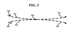
次に図3を参照すると、例示的光ファイバ210、220間の関係が、より詳細に示されている。光ファイバ210は、接点230で接続された第1部分212及び第2部分214を有することができる。同様に、光ファイバ220は、接点230で接続された第1部分222及び第2部分224を有することができる。第1ファイバ210に沿って移動する光信号を、接点230で第2ファイバ220に移送することができる。同様に、第2ファイバ220に沿って移動する光信号を、接点230で第1ファイバ210に移送することができる。参照しやすいように、ファイバ210、220を各部分に分割したが、ファイバ210、220それぞれは、物理的に単一の連続的光ファイバでよいことを理解されたい。
Referring now to FIG. 3, the relationship between exemplary
この実施形態の構造及び接続性を説明したので、図4に示すように、WDM結合装置100の動作の例示的方法400を、次に説明することができる。ステップ402では、WDM結合装置100を、結合装置100内の熱ゆらぎを生み出す周囲温度の変化(例えば温度上昇)にさらすことができる。熱ゆらぎは、光ファイバ210、220の一方又は両方の屈折率を変更し、又は光ファイバ210、220を膨張させるなどにより、光ファイバ210、220の固有特性に対する変化を引き起こす。
Having described the structure and connectivity of this embodiment, an
更に、光ファイバ210、220の固有特性に対するこうした変化は、WDM結合装置100の固有平均分割波長もシフトさせる可能性があり、従って、その分割比を変更する可能性がある。従って、光ファイバ210、220に沿って移動するWDM光信号は、温度変化後ではその前とは異なる仕方で分割され、又は屈折する可能性がある。
Furthermore, such changes to the intrinsic characteristics of the
ステップ404では、プラグ130、150(高CTEを有することができる)は、温度変動のために、半径方向及び/又は縦方向のサイズが変化する可能性がある。この実施形態では、プラグ130、150は、温度が上昇した場合に膨張することができ、温度が低下した場合に収縮することができるが、これは代替実施形態では変化することがある。
In
ステップ406では、ケーシング110は、そのCTEが小さいために、温度変動に応答して、そのサイズ変化に抵抗することができる。従って、ケーシング110は、プラグ130、150と比較して、その半径及び/又は物理的長さの変化が小さい。例えば、例示的実施形態では、温度変動が温度上昇である場合、プラグ130、150は、ケーシング110よりも膨張することができ、従って、ケーシング110は、プラグ130、150の膨張を結合装置100の中心に向けて内側に導くことができる。
In
ステップ408では、前述のように、温度上昇中のプラグ130、150の膨張が、光ファイバ210、220に機械的力(例えば応力、ひずみ)を加え、それが結合領域188を収縮させる。結合領域188の収縮は、熱ゆらぎによって誘発された光ファイバ210、220に対する固有の変化を打ち消すことができる。あるいは、周囲温度の低下中、プラグ130、150のサイズが減少することができ、従って、熱ゆらぎによって誘発された変化を相殺するために結合領域188を引き伸ばす。
In
ステップ410では、結合装置100の元の波長依存性を実質上復元することができ、結合装置100は、その元の平均分割波長を実質上維持することができる。
この方法400は、結合装置104などの代替の例示的結合装置にも適用できることを理解されたい。更に、代替実施形態では、3つ以上の光ファイバを使用することができ、様々な方式でファイバ間で光を移送することができる。
In
It should be understood that the
本願で開示した例示的結合装置100、104は、幾つかの利点を有する。結合装置100、104は、温度依存の機械的力を使用して結合装置の固有特性に対する温度依存の変化を相殺することができる。従って、このWDM結合装置100、104は、温度変化に対してより影響を受けにくく、WDM信号をより正確に分割することができる。更に、結合装置100、104の精度の向上は、どんな最小の追加のコストよりも重要であるので、結合装置100、104は、実装するのに費用対効果が高い。
The
上述のWDM結合装置100の諸実施形態に対して、多種多様な変更及び修正を行えることを理解されたい。例えば、代替実施形態では、結合装置100で3つ以上の光ファイバ210、220を互いに結合することができる。更に、代替実施形態では、ケーシング110、プラグ130、150、コア180、及び/又は光ファイバ210、220はそれぞれ、矩形プリズムなどの異なる形状を有することができる。従って、上記の説明は、本発明を限定するものではなく、本発明を定義するのは、すべての均等物を含めて、添付の特許請求の範囲であるものとする。
It should be understood that a wide variety of changes and modifications can be made to the embodiments of the
Claims (23)
第1熱膨張係数を有する第1領域と、
前記光ファイバに前記第1領域を接続する少なくとも1つのマウンティング・ポイントと、
を備え、
前記熱ゆらぎは、前記第1領域のサイズの変化を引き起こし、第1領域のサイズの変化は、結合装置に関連する平均分割波長の変化を実質上制限する、結合装置。 A coupling device for an optical fiber, wherein the thermal fluctuation causes a change in the average split wavelength associated with the coupling device,
A first region having a first coefficient of thermal expansion;
At least one mounting point connecting the first region to the optical fiber;
With
The thermal fluctuation causes a change in the size of the first region, the change in the size of the first region substantially limiting a change in average split wavelength associated with the coupling device.
前記第1領域に接続された第2領域を、
さらに備え、
前記第2領域は、前記第1熱膨張係数よりも小さい第2熱膨張係数を有する、結合装置。 The coupling device according to claim 1,
A second region connected to the first region;
In addition,
The coupling device, wherein the second region has a second coefficient of thermal expansion that is smaller than the first coefficient of thermal expansion.
さらに備え、
前記第3領域は、前記第2熱膨張係数よりも大きい第3熱膨張係数を有する、結合装置。 The coupling device according to claim 7, wherein a third region connected to the second region is
In addition,
The coupling device, wherein the third region has a third coefficient of thermal expansion that is greater than the second coefficient of thermal expansion.
第1マウンティング・ポイントを介して前記第1領域に接続され、第2マウンティング・ポイントを介して第3領域に接続された光ファイバと、
を備える結合システムであって、
温度上昇は、前記第1領域の膨張と、前記第3領域の膨張と、を引き起こし、その結果、前記第1マウンティング・ポイントと前記第2マウンティング・ポイントとの間の距離が、減少する、結合システム。 A first region having a first coefficient of thermal expansion; a second region having a second coefficient of thermal expansion less than the first coefficient of thermal expansion; and a third region having a third coefficient of thermal expansion greater than the second coefficient of thermal expansion. A coupling device comprising:
An optical fiber connected to the first region via a first mounting point and connected to the third region via a second mounting point;
A combined system comprising:
An increase in temperature causes expansion of the first region and expansion of the third region, so that the distance between the first mounting point and the second mounting point is reduced. system.
第2熱膨張係数を有するケーシングと、
第3熱膨張係数を有する第2プラグであって、前記ケーシングによって前記第1プラグに接続される第2プラグと、
を備える結合装置であって、
光ファイバは、前記第1プラグ及び第2プラグを通過し、前記第1熱膨張係数と前記第3熱膨張係数はどちらも、前記第2熱膨張係数よりも大きい、結合装置。 A first plug having a first coefficient of thermal expansion;
A casing having a second coefficient of thermal expansion;
A second plug having a third coefficient of thermal expansion, wherein the second plug is connected to the first plug by the casing;
A coupling device comprising:
An optical fiber passes through the first plug and the second plug, and the first thermal expansion coefficient and the third thermal expansion coefficient are both greater than the second thermal expansion coefficient.
Applications Claiming Priority (2)
| Application Number | Priority Date | Filing Date | Title |
|---|---|---|---|
| US10/355,464 US7095910B2 (en) | 2003-01-31 | 2003-01-31 | Wavelength division multiplexing coupling device |
| PCT/US2004/002306 WO2005022225A1 (en) | 2003-01-31 | 2004-01-27 | Athermal wavelength division multiplexing coupler |
Publications (2)
| Publication Number | Publication Date |
|---|---|
| JP2006517689A true JP2006517689A (en) | 2006-07-27 |
| JP2006517689A5 JP2006517689A5 (en) | 2006-11-24 |
Family
ID=32770536
Family Applications (1)
| Application Number | Title | Priority Date | Filing Date |
|---|---|---|---|
| JP2006508628A Pending JP2006517689A (en) | 2003-01-31 | 2004-01-27 | Non-thermal wavelength division multiplexing coupler |
Country Status (4)
| Country | Link |
|---|---|
| US (1) | US7095910B2 (en) |
| EP (1) | EP1629310A1 (en) |
| JP (1) | JP2006517689A (en) |
| WO (1) | WO2005022225A1 (en) |
Families Citing this family (5)
| Publication number | Priority date | Publication date | Assignee | Title |
|---|---|---|---|---|
| US20080129980A1 (en) * | 2006-11-30 | 2008-06-05 | North Carolina State University | In-line fiber optic sensor devices and methods of fabricating same |
| FI125081B (en) | 2011-01-11 | 2015-05-29 | Rofin Sinar Laser Gmbh | A housing for a fiber optic component and a method for making it |
| CN102221422A (en) * | 2011-04-01 | 2011-10-19 | 上海大学 | Intrinsic optical fiber Fabry-Perot temperature sensor manufactured by femtosecond pulse laser and manufacturing method of temperature sensor |
| CN102508337B (en) * | 2011-11-03 | 2013-03-06 | 上海大学 | Optical fiber fused taper-based intrinsic Fabry-Perot device and manufacturing method thereof |
| US9181818B2 (en) * | 2012-09-25 | 2015-11-10 | United Technologies Corporation | Thermally constrained high temperature optical fiber holder |
Family Cites Families (30)
| Publication number | Priority date | Publication date | Assignee | Title |
|---|---|---|---|---|
| US5007705A (en) * | 1989-12-26 | 1991-04-16 | United Technologies Corporation | Variable optical fiber Bragg filter arrangement |
| US5042898A (en) * | 1989-12-26 | 1991-08-27 | United Technologies Corporation | Incorporated Bragg filter temperature compensated optical waveguide device |
| CA2105605A1 (en) * | 1993-09-07 | 1995-03-08 | Zhuo Jun Lu | Fiber optic sensor system for strain and temperature measurement |
| US5416867A (en) * | 1993-12-29 | 1995-05-16 | At&T Corp. | Passive temperature-compensated optical wave guide coupler |
| US5555330A (en) * | 1994-12-21 | 1996-09-10 | E-Tek Dynamics, Inc. | Wavelength division multiplexed coupler with low crosstalk between channels and integrated coupler/isolator device |
| JP3092499B2 (en) * | 1995-12-04 | 2000-09-25 | 日本電気株式会社 | Waveguide type optical multiplexing / demultiplexing module |
| US5796889A (en) * | 1996-03-13 | 1998-08-18 | E-Tek Dynamics, Inc. | Integrated WDM coupler devices for fiberoptic networks |
| JP3294986B2 (en) * | 1996-03-22 | 2002-06-24 | 富士通株式会社 | Optical element without temperature dependence |
| US5694503A (en) * | 1996-09-09 | 1997-12-02 | Lucent Technologies Inc. | Article comprising a temperature compensated optical fiber refractive index grating |
| US5844667A (en) * | 1997-01-28 | 1998-12-01 | Cidra Corporation | Fiber optic pressure sensor with passive temperature compensation |
| US5987200A (en) * | 1997-10-27 | 1999-11-16 | Lucent Technologies Inc. | Device for tuning wavelength response of an optical fiber grating |
| US6081641A (en) * | 1997-11-03 | 2000-06-27 | Applied Fiber Optics, Inc. | Thermal compensated fused-fiber dense wavelength division multiplexer |
| AU736870B2 (en) * | 1997-11-24 | 2001-08-02 | Koheras A/S | Temperature stabilization of optical waveguides |
| EP1064576A1 (en) * | 1998-03-17 | 2001-01-03 | Minnesota Mining And Manufacturing Company | Passively compensated optical fibers |
| US6144788A (en) * | 1998-06-30 | 2000-11-07 | Honeywell, Inc. | High stability fiber light source |
| US6422084B1 (en) * | 1998-12-04 | 2002-07-23 | Weatherford/Lamb, Inc. | Bragg grating pressure sensor |
| US6621957B1 (en) * | 2000-03-16 | 2003-09-16 | Cidra Corporation | Temperature compensated optical device |
| JP2000266943A (en) | 1999-03-12 | 2000-09-29 | Nippon Electric Glass Co Ltd | Temperature compensation device for optical communication |
| US6347170B1 (en) * | 1999-05-06 | 2002-02-12 | Jds Uniphase, Inc. | Low-cost wavelength division multiplexed (WDM) coupler with more flexible and precise optical faith adjustment |
| US6246048B1 (en) * | 1999-05-18 | 2001-06-12 | Schlumberger Technology Corporation | Methods and apparatus for mechanically enhancing the sensitivity of longitudinally loaded fiber optic sensors |
| US6377727B1 (en) * | 1999-05-25 | 2002-04-23 | Thomas & Betts International, Inc. | Passive temperature-compensating package for fiber Bragg grating devices |
| US6144789A (en) * | 1999-05-25 | 2000-11-07 | Lucent Technologies Inc. | Temperature compensating device for fiber gratings and a package therefor |
| US6349165B1 (en) * | 1999-12-13 | 2002-02-19 | Corning Incorporated | Methods and apparatus for cylindrical packaging of fiber gratings to provide temperature compensation |
| US6411746B1 (en) * | 2000-01-18 | 2002-06-25 | Corning Incorporated | Thermally tunable optical devices |
| US6327405B1 (en) * | 2000-03-03 | 2001-12-04 | Arroyo Optics Inc. | Devices and methods for temperature stabilization of Bragg grating structures |
| US6385372B1 (en) * | 2000-04-19 | 2002-05-07 | Tera Fiberoptics, Inc. | Fiber optical coupler fabrication and system |
| US6453092B1 (en) * | 2000-12-22 | 2002-09-17 | Corning Incorporated | Temperature compensated optical device |
| WO2002075405A2 (en) * | 2001-03-16 | 2002-09-26 | Cidra Corporation | Multi-core waveguide |
| GB0119033D0 (en) * | 2001-08-03 | 2001-09-26 | Southampton Photonics Ltd | An optical fibre thermal compensation device |
| US6636667B2 (en) * | 2001-12-06 | 2003-10-21 | Oplink Communications Inc. | Tunable optical fiber grating package with low temperature dependency |
-
2003
- 2003-01-31 US US10/355,464 patent/US7095910B2/en not_active Expired - Fee Related
-
2004
- 2004-01-27 EP EP04775735A patent/EP1629310A1/en not_active Withdrawn
- 2004-01-27 WO PCT/US2004/002306 patent/WO2005022225A1/en active Application Filing
- 2004-01-27 JP JP2006508628A patent/JP2006517689A/en active Pending
Also Published As
| Publication number | Publication date |
|---|---|
| US20040151424A1 (en) | 2004-08-05 |
| US7095910B2 (en) | 2006-08-22 |
| EP1629310A1 (en) | 2006-03-01 |
| WO2005022225A1 (en) | 2005-03-10 |
Similar Documents
| Publication | Publication Date | Title |
|---|---|---|
| US10845555B2 (en) | Optical module and associated methods | |
| EP1144969B1 (en) | Strain-isolated bragg grating temperature sensor | |
| US9411100B2 (en) | Photonic lantern spatial multiplexers with mode selectivity | |
| US20170219774A1 (en) | Polarization maintaining optical fiber array | |
| US20020172446A1 (en) | Pressure-isolated Bragg grating temperature sensor | |
| JP3377729B2 (en) | Optical waveguide system | |
| JP2002131575A (en) | Coaxial optical coupler and manufacturing method | |
| US11402585B2 (en) | Optical connection structure | |
| EP2878922B1 (en) | Resonant fiber optic gyroscopes with multi-core transport fiber | |
| JP2006517689A (en) | Non-thermal wavelength division multiplexing coupler | |
| JP4227101B2 (en) | Athermal package for multiple fiber Bragg gratings having two or more junction sites | |
| US6731841B1 (en) | Folded waveguide optical devices | |
| CA2357991C (en) | Optical phase shifting, splitting and combining device | |
| WO1998015856A1 (en) | Sensor apparatus with polarization maintaining fibers | |
| US20070009196A1 (en) | Integrated dual waveguides | |
| WO2020022157A1 (en) | Interferometric optical fiber gyroscope and sensing coil mechanism | |
| WO2020257660A1 (en) | Multifiber connector for concentric multi-core fiber | |
| US7065267B2 (en) | Athermal fused coupler package for optical fibers | |
| JP4206964B2 (en) | Optical splitter | |
| US20040033012A1 (en) | Wavelength division multiplexer | |
| KR100386778B1 (en) | optical fiber interferometer type wavelength multi/demultiplexor | |
| Natarajan et al. | Design of a Multimode Interference Splitter/Combiner for Sensor Applications | |
| JPH02257110A (en) | Structure for connecting optical fiber and optical waveguide | |
| JPS62116903A (en) | Polarized wave separation type single mode optical fiber coupler | |
| US20030165317A1 (en) | Substrate with multiple optically isolated grooves and method for using same |
Legal Events
| Date | Code | Title | Description |
|---|---|---|---|
| A521 | Written amendment |
Free format text: JAPANESE INTERMEDIATE CODE: A523 Effective date: 20061005 |
|
| A621 | Written request for application examination |
Free format text: JAPANESE INTERMEDIATE CODE: A621 Effective date: 20061005 |
|
| A977 | Report on retrieval |
Free format text: JAPANESE INTERMEDIATE CODE: A971007 Effective date: 20081003 |
|
| A131 | Notification of reasons for refusal |
Free format text: JAPANESE INTERMEDIATE CODE: A131 Effective date: 20081105 |
|
| A521 | Written amendment |
Free format text: JAPANESE INTERMEDIATE CODE: A523 Effective date: 20090128 |
|
| A02 | Decision of refusal |
Free format text: JAPANESE INTERMEDIATE CODE: A02 Effective date: 20090623 |