FIELD OF THE INVENTION
This invention relates to temperature stabilization of optical devices and components for optical communications systems, and more particularly to systems and methods for temperature stabilization of Bragg grating structures used in add/drop filter systems and the like.
BACKGROUND OF THE INVENTION
Wideband communication systems using optical signals now commonly employ wavelength division multiplexing (WDM) or dense wavelength division multiplexing (DWDM) to transfer and transmit vast amounts of data at very high data rates. In these multiplexing systems, multiple signal-bearing channels are centered on specified spaced apart wavelengths and sources (e.g. lasers) are set to those wavelengths. Whether combining signals into the multiplex format, or demultiplexing by separating or dropping out signals, the filters and couplers used must have center wavelength stability, with a high degree of precision. This in turn means that temperature variations cannot be permitted to affect operation over a substantial range, such as 0-70° C. For a number of reasons, Bragg grating devices are widely employed in wavelength division multiplex systems because a precise wavelength response can be set by selection of the periodicity of the grating written in a device. Because the periodicity of the grating is affected by temperature, however, due to the temperature coefficient of the waveguide or fiber material, the wavelength selectivity can be unacceptably changed by ambient conditions. For example, without any form of temperature compensation, the center wavelength can vary by as much as +0.01 nm/C. Channel placements and bandwidths for individual signals are such that this amount of variation of length, in a normal temperature environment, would shift the wavelength selectivity such that the coupler or filter is no longer matched to the wavelength of the corresponding laser or other source.
In a prior application, Ser. No. 09/128,476 entitled “Methods of Fabricating Grating Assisted Coupler Devices”, filed Aug. 4, 1998 by Anthony S. Kewitsch, et al., and assigned to the assignee of the present invention, this problem is confronted by a disclosed temperature compensation system in which a “prepackage” or support structure is disposed within a cylindrical housing, with the prepackage structure using a number of spaced apart hubs mounted on and/or selectively movable relative to Invar rods. The prepackage structure enables attachment of a span of a fiber-based coupler, and the arrangement provides for the use of thermally dissimilar metal elements (stainless steel) and adjustment means for varying the strain on the critical fiber length which includes a Bragg grating. While this arrangement is fully satisfactory from the operational standpoint, and provides for the needed tensioning of the fiber optic components during the initial writing phase and thereafter despite temperature variations, it is more complex than desirable for high production processes. Further, it is desirable to provide even better temperature compensation, to a level of + or −0.001 nm/° C. center wavelength variation over temperature. In addition, it is desirable to provide means for axial twisting of the fiber optic component, for purposes of achieving polarization independence and reducing polarization mode dispersion (PMD).
SUMMARY OF THE INVENTION
Devices in accordance with the invention suspend the waist region of a fused fiber coupling closely along a base support having a low thermal coefficient of expansion (i.e. Invar or ceramic). The ends of the span are held in spaced apart compensating elements of higher expansion material (e.g. stainless steel) which are attached to the ends of the base support, and have expandable lengths, in relation to their temperature coefficients of expansion, to tend to move the mounting points inwardly to compensate for the thermal expansion of the base support. The net adjustment is arranged to be precisely enough to counteract the effect of temperature on the span. Each end of the span of optical fiber that includes the Bragg grating is mounted in a holder, such as a split-sleeve ferrule, which can be rotated so as to impart a degree of twist to the waist region, compensating for polarization dependence and PMD. This arrangement permits ready assembly of a minimum number of parts and enables fine tuning of both temperature compensation and strain on the suspended span of optical fiber so as to set the desired wavelength selectivity.
Methods of assembling a temperature compensated fused fiber coupler first elongate one or more lengths of optical fibers to form a small diameter waist region. A fused elongated fiber section is mounted under tension between elements that are held on a temporary carrier, to define a span which can be exposed to an illumination pattern, which writes the Bragg grating to provide a selected nominal periodicity. The span is then transferred to the temperature compensated structure, together with the end elements, which can be rotated about the longitudinal axis of the span to reduce polarization dependence and polarization mode dispersion. Then the unit is temperature cycled and the wavelength response of the filter is monitored using a broadband light source and a wavemeter. The temperature compensating structure can be adjusted by varying the relatively expandable lengths of the compensating elements, and the grating periodicity can be fine tuned by incremental shifting of the end elements on their supports.
This arrangement also has the advantage that it facilitates incorporation of a number of temperature compensated couplers in a single housing for assembly of multiplexers and demultiplexers. For this purpose, optical fibers splice together the separate couplers in the desired circuit pattern. The couplers are physically independent, however, being held in the housing in an elastomeric mold which does not introduce any stress that might cause wavelength shifts, or effect the temperature compensation action.
A number of specific features in accordance with the invention contribute to the usefulness of the apparatus and process. In the temperature compensated structure the elongated low expansion base supports spaced apart planar compensating elements which are attached to the base at the ends opposite the intermediate tensioned fiber span. The attachment is advantageously accomplished along a joinder length by laser welding, and the distance between the opposed weld ends (as well as the lengths of the compensating elements that are free to move relative to the base) determine the temperature compensating characteristic. Fine tuning is readily feasible by further precise welding along the joinder line. The mounts for the tensioned fiber spans are in this example cylindrical ferrules with at least one slot for receiving pairs of fibers at one end of the waist region, so that the needed degree of twist can be imprinted by rotation of one or both ferrules about the longitudinal axis of the tensioned span. In addition, micro-adjustments of tension and therefore wavelength sensitivity can be made by laser beam imprints, known as laser “hammering”.
The low expansion coefficient base can alternatively be of a non-metallic material such as a ceramic. In this event a conductive coating can be used on end surfaces of the base, so that sheet elements of stainless steel or other metal can be brazed on, to receive separate compensating pads which can then be laser welded.
BRIEF DESCRIPTION OF THE DRAWINGS
A better understanding of the invention may be had by reference to the following description, taken in conjunction with the accompanying drawings, in which:
FIG. 1 is a perspective view, partially broken away, of a temperature compensated package for a Bragg grating coupler or filter in accordance with the invention;
FIG. 2 is a side view of a portion of the arrangement of FIG. 1, showing the disposition of elements of the temperature compensating structure therein;
FIG. 3 is a perspective view of a part of the structure of FIGS. 1 and 2;
FIG. 4 is an enlarged fragmentary side sectional view of the end portion of a temperature compensated unit of FIGS. 1-3;
FIG. 5 is a graph of wavelength response in nanometers versus temperature variations in degrees C for a Bragg grating device that is to be temperature compensated;
FIG. 6 is a graph of variations in wavelength response versus length for a Bragg grating device;
FIG. 7 is a graph of variations in wavelength response in relation to temperature for a temperature compensated package in accordance with the invention;
FIG. 8 is a flow chart showing steps that may be employed in assembling and packaging a temperature compensated Bragg grating device;
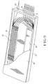
FIG. 9 is a perspective view, partially broken away, of a temperature compensated unit for a number of couplers and/or filters intercoupled in a single housing;
FIG. 10 is a fragmentary perspective view, partially broken away, of a position of the unit of FIG. 9; and
FIG. 11 is a fragmentary end section view of portions of a temperature compensated unit employing a base of ceramic material.
DETAILED DESCRIPTION OF THE INVENTION
Reference should be made to FIGS. 1-4, which depicts a temperature compensated structure for Bragg grating devices. The Bragg grating device 10 that is used as an example here is of the type described in Kewitsch et al U.S. Pat. No. 5,805,751 and includes a small diameter (less than 15 microns) waist region 12 of two longitudinally merged optical fibers 14, 15 including a reflective Bragg grating 17 of a selected nominal periodicity. Given the small diameter the periodicity of the grating varies with the tension on the waist, which in turn, if the span of the waist 12 is held fixed, varies with temperature because of the positive thermal coefficient of expansion of the fibers 14,15. U.S. Pat. No. 5,805,751 further describes how the ends of the waist 12 extend outwardly through pairs of tapered fiber section 19, 20 which diverge in diameter to a standard (e.g. 95-125 micron) optical fiber size.
A span of optical fibers that includes the waist 12 and extending tapered sections 19, 20 is formed between end supports, described hereafter. The separate optical fiber couples, as seen particularly in FIG. 1, to an input port or source 22 and drop port 23 on one side of the waist, and a through port 25 and add port 26 on the other. The span is held at each end in cylindrical ferrules 30, 31 of “Kovar” material that are secured on a temperature compensating structure, specifically on separate spaced apart temperature compensating elements 33, 34 in the form of rectangular pads each attached to an opposite end of an elongated base 36. The base 36 has a substantially planar surface close to the level of the planar surface and the ferrules 30, 31 hold the fiber span above the planar surface, as best seen in FIGS. 2 and 4. The entire unit is typically mounted within a sealed housing 38, only a fragment of which is shown in FIG. 3, and the fibers 14, 15 exit the housing through fiber feedthroughs 40, 41 in the end walls of the housing 38. (FIG. 9 depicts a housing construction in greater detail.) The base 36 and compensating elements 33, 34 are of materials having different thermal coefficients of expansion—in this example “Invar 36”, a low coefficient material, is used for the base, and 304 Stainless Steel is used for the compensating elements.
The paired fiber ends of the coupler are epoxied in longitudinal slots in each ferrule 30, 31 using a material such as “EpoTek353ND”. The epoxy is in contact with bare glass on the inside end of the ferrule 30 or 31, because protective material is removed for elongation, and in contact with the fiber buffer on the outside of the respective ferrule 30 or 31. The ferrules 30, 31 are attached with the fiber under tension to the stainless steel compensating elements 33, 34 using laser welding. Small upstanding panels 35 on the compensating elements provide convenient attachment and reference points for the ferrules. Before attachment the ferrules 30, 31 with the fiber span attached are rotated a number of times (for example ten) in order to minimize the polarization sensitivity of the device. The compensating elements 33, 34 are attached at the outer ends to the base 36 with laser welding, providing facing lengths of compensating metal that are free to move toward each other in opposite directions to expansion of the base 36. The length of the base is 4.9″ while the compensating elements are 0.75″ in length in this practical example. The optimal weld position between the compensating elements 33, 34 and the base 36 was found to be approximately 0.145″ from the outer end, but as described below, the final position is determined by monitoring temperature-induced deviations under test conditions.
These coupler grating filters are 2×2 fused fiber couplers in which the Bragg grating 17 is written in the tapered down fused waist 12 of the coupler. When the fiber is under tension, the change in wavelength of the filter, Δλ, as the temperature varies by ΔT, is given by:
Δλ/λ=(α+ζ)ΔT+(1−p)Δε (equ 1)
where α is the thermal expansion coefficient of the fiber, ζ is the thermooptic coefficient, Δε is the change in strain, and p is the photoelastic constant. As the temperature is increased, a negative value of strain can cancel the first term leading to no wavelength shift of the filter. The strain on tapered fibers is non uniform and varies inversely with the cross sectional area. The strain is mainly concentrated in the narrow tapered regions.
Various combinations of two materials with different positive thermal expansion coefficients can be used to give the required negative thermal expansion package, but it is convenient to use laser welding to control the precise points of attachment. The compensating elements 33, 34 have facing cantilevered ends which are free to translate relative to the base 36. As the temperature is increased the compensating elements 33, 34 expand inwardly faster than the base 36 expands outwardly. This results in the ferrules 30, 31 moving toward each other, giving a negative thermal expansion coefficient for the assembly. The temperature compensation depends on the location of the welds i.e. the distance between the weld points which are closest and the free lengths of the compensating elements 33, 34. The center wavelength depends on the tension of the waist 12 determined by the spacing between the ferrules 30, 31. Even after the elements are attached laser welding can effect slight tuning of both of these parameters. After testing under temperature cycling conditions the juncture between the elements 33, 34 and the base 36 can be correctively welded to adjust the temperature compensation range. Laser hammering, a process which induces small positional shifts during a weld operation, can also be used to shift the ferrules 30, 31 minutely to selectively tune the center wavelength of the filter. FIG. 7 demonstrates the small wavelength shift of a filter packaged in an example of a temperature compensated package.
FIG. 5 shows the change in wavelength of a coupler grating mounted on a non temperature compensated “Invar” package as the temperature is varied. Typical values are +0.01 nm/C. Because “Invar” has a small expansion coefficient the variation is mainly due to the first term in (1). FIG. 6 shows the change in wavelength of a filter as it is stretched. Typical tuning values are +0.036 nm/micron. If the tension of the fiber is decreased as the temperature is increased the filter will be temperature compensated and not change wavelength. The practical requirements for temperature compensation dictate a package with a typical negative thermal expansion of −(+0.01 nm/C.)/(0.036 nm/um)=−0.278 micron/C. These goals are met in a practical device in accordance with the invention, as shown in FIG. 7, the measured plot of wavelength vs. temperature for two different measurements.
Methods in accordance with the invention, referring now to FIG. 8, first form the waist region of a fiber coupler by stretching two merged fibers of photosensitized material to a small diameter cross section, from which the tapered lengths extend outwardly in opposite directions. The tapered ends are seated in retainers (such as ferrules) which are then mounted on a temporary fixture which holds the waist region in a tensioned span. A Bragg grating is written by patterned illumination of the photosensitive waist region. This imparts a nominal periodicity to the Bragg grating, which must be both precisely tuned and temperatures compensated. The span supports and the narrowed coupler base between them are then ready to be transferred to a temperature compensating base. This is preliminarily prepared by attaching two compensating elements at spaced apart positions on an elongated base, with predetermined approximate spacings between them. The relatively shorter compensating elements have free lengths which counteract expansion of the longer but lower thermal expansion base. The span supports are mounted on these free ends, with span tension adjusted to a nominal periodicity, for a selected wavelength response. Measuring the wavelength response at different temperature levels, the physical geometry of the base and compensating elements can be changed to center the temperature compensation. Finally, the span supports can be finely adjusted relative to the compensating elements, as by laser hammering on the supports.
To construct a demultiplexer, a number of the temperature compensated filter elements 50 are placed in an aluminum tray 52 (FIGS. 9 and 10). Fiber feedthroughs 54 with strain relief boots (not shown in detail) are used to couple fiber through the walls of the tray 52. The filter elements 50 are placed in grooves in a ribbed silicone mold 56 (best seen in FIG. 10) and attached with RTV or similar adhesive. The devices 50 are spliced together and to the appropriate output fibers by optical fiber loops. A cover or lid 60 is sealed to the tray 52 is sealed in a dry nitrogen atmosphere using epoxy which forms a water tight seal.
The multiple temperature compensated coupler grating filters 50 are conveniently and compactly mounted in substantial parallelism inside of the support tray 52. The ribbed silicone mold 52 holds the filters 50 without applying stress, which could cause wavelength shifts. It also allows for the free expansion of the materials over the temperature range necessary for temperature compensation and provides cushioning from shock and vibration. The tray 52, including the conforming lid 60, is sealed with epoxy to provide a watertight seal.
As shown in FIG. 10, any bare fiber regions, particularly the tapered lengths, up to but not including the waist region can be recoated by using a UV curable acrylate coating such as “Desolite 950” from DSM Desotech Corporation. This helps protect the fiber from any mechanical or environmental damage. The filter elements 50 can be additionally protected from vibrational damage by placing a viscoelastic damping material 68 such as is supplied by Sorbethane Corporation underneath the silicone molds 56, an internal cover 59, only one of which is shown, can be placed over the sets of filters 50 for further protection.
Another example of temperature compensated package is one which uses a base of low expansion ceramic glass such as is available from Nippon Electric and Glass (NEG) instead an “Invar” or other metal base. As shown in FIG. 11, the ceramic base 64 is metallized on the ends which receive compensation elements 66 using an AuSn layer 67. This allows stainless steel sheet metal pieces 68 to be brazed to each end of the base 62 in this region, so that the compensating elements 66 can then welded to the stainless pieces 68.
Although various forms and modifications have been described above and illustrated in the drawings, the invention is not limited thereto but encompasses all alternatives and variations within the scope of the appended claims.