JP2006517308A - Method and apparatus for cooling portable computer - Google Patents
Method and apparatus for cooling portable computer Download PDFInfo
- Publication number
- JP2006517308A JP2006517308A JP2004512194A JP2004512194A JP2006517308A JP 2006517308 A JP2006517308 A JP 2006517308A JP 2004512194 A JP2004512194 A JP 2004512194A JP 2004512194 A JP2004512194 A JP 2004512194A JP 2006517308 A JP2006517308 A JP 2006517308A
- Authority
- JP
- Japan
- Prior art keywords
- port
- heat conducting
- housing
- flow
- heat
- Prior art date
- Legal status (The legal status is an assumption and is not a legal conclusion. Google has not performed a legal analysis and makes no representation as to the accuracy of the status listed.)
- Pending
Links
Images


Classifications
-
- H—ELECTRICITY
- H01—ELECTRIC ELEMENTS
- H01L—SEMICONDUCTOR DEVICES NOT COVERED BY CLASS H10
- H01L23/00—Details of semiconductor or other solid state devices
- H01L23/34—Arrangements for cooling, heating, ventilating or temperature compensation ; Temperature sensing arrangements
- H01L23/46—Arrangements for cooling, heating, ventilating or temperature compensation ; Temperature sensing arrangements involving the transfer of heat by flowing fluids
- H01L23/467—Arrangements for cooling, heating, ventilating or temperature compensation ; Temperature sensing arrangements involving the transfer of heat by flowing fluids by flowing gases, e.g. air
-
- G—PHYSICS
- G06—COMPUTING; CALCULATING OR COUNTING
- G06F—ELECTRIC DIGITAL DATA PROCESSING
- G06F1/00—Details not covered by groups G06F3/00 - G06F13/00 and G06F21/00
- G06F1/16—Constructional details or arrangements
- G06F1/20—Cooling means
- G06F1/203—Cooling means for portable computers, e.g. for laptops
-
- H—ELECTRICITY
- H01—ELECTRIC ELEMENTS
- H01L—SEMICONDUCTOR DEVICES NOT COVERED BY CLASS H10
- H01L23/00—Details of semiconductor or other solid state devices
- H01L23/34—Arrangements for cooling, heating, ventilating or temperature compensation ; Temperature sensing arrangements
- H01L23/36—Selection of materials, or shaping, to facilitate cooling or heating, e.g. heatsinks
- H01L23/367—Cooling facilitated by shape of device
- H01L23/3672—Foil-like cooling fins or heat sinks
-
- H—ELECTRICITY
- H01—ELECTRIC ELEMENTS
- H01L—SEMICONDUCTOR DEVICES NOT COVERED BY CLASS H10
- H01L2924/00—Indexing scheme for arrangements or methods for connecting or disconnecting semiconductor or solid-state bodies as covered by H01L24/00
- H01L2924/0001—Technical content checked by a classifier
- H01L2924/0002—Not covered by any one of groups H01L24/00, H01L24/00 and H01L2224/00
Abstract
ポータブルコンピュータ(10)は、回路部材(36)と温度調節装置(41、441)とを有するハウジングを有し、この温度調節装置は、軸(158)に略沿って対向し上記の部材に熱結合された側面を有する熱伝導部(141、241、341、441、541)を有する。流体供給部(121)は、上記の軸に沿って流体を流動させ、熱伝導部は、上記の流体を複数の流動部分に分割し、そのそれぞれは、熱伝導部に沿って、上記の軸に平行な平面に略平行な方向へと流動する。上記の流動部分は、熱伝導部の周辺の実質的な部分に沿って配置された複数の個々の位置において、熱伝導部に存在する。The portable computer (10) has a housing having a circuit member (36) and a temperature control device (41, 441), which is generally opposed along the axis (158) and that heats the member. It has a heat conduction part (141, 241, 341, 441, 541) having a joined side surface. The fluid supply part (121) causes the fluid to flow along the axis, and the heat conduction part divides the fluid into a plurality of flow parts, each of which is located along the heat conduction part and the axis. It flows in a direction substantially parallel to a plane parallel to. The flow part is present in the heat conducting part at a plurality of individual positions arranged along a substantial part around the heat conducting part.
Description
(本発明の技術分野)
本発明は、一般に、回路装置を冷却する技術に係り、特に、ポータブルコンピュータ内に配置された回路装置を冷却する技術に関する。
(Technical field of the present invention)
The present invention generally relates to a technique for cooling a circuit device, and more particularly, to a technique for cooling a circuit device arranged in a portable computer.
(本発明の背景技術)
過去15年来、いわゆる「ラップトップ型」及び「ノートブック型」コンピュータなどのポータブルコンピュータを含むパーソナルコンピュータは、持続的に知名度を増加させてきた。これらと同時期の間、ポータブルコンピュータを含むパーソナルコンピュータに使用されるプロセッサのデザインは有意に進化を遂げてきた。これに関連して、集積回路の所定の領域で製作され得る回路の数量は有意に増加し、これにより、より洗練されたプロセッサのデザインの実行及び製作が促進している。さらに、プロセッサの動作許容性は、劇的に向上し、プロセッサが動作可能な速度も有意に増加している。
(Background of the present invention)
Over the past 15 years, personal computers, including portable computers such as so-called “laptop” and “notebook” computers, have been continuously gaining popularity. During these same periods, the design of processors used in personal computers including portable computers has evolved significantly. In this regard, the number of circuits that can be fabricated in a given area of the integrated circuit is significantly increased, which facilitates the implementation and fabrication of more sophisticated processor designs. Furthermore, the operational tolerance of the processor has improved dramatically and the speed at which the processor can operate has also increased significantly.
これらの技術的な進歩の副作用には、パーソナルコンピュータに使用される最先端のプロセッサ及びその他の集積回路が、通常動作中に、先行技術におけるプロセッサがたった数年前に行っていた動作中に発生するよりも有意に多くの熱を発生する点である。幾つかのシステムにおいて、プロセッサ及び関連する部材は、熱発生量を低下させ且つ活動的な冷却を行う必要性を排除するため、これらに関連する最大レートのクロック速度よりも有意に低いクロックスピードで動作される。しかしながら、その最大レートの速度未満の速度でプロセッサを動作させることは、システムの許容性を減少させ、従って、コンシューマーからみたシステムの価値が減少してしまい望ましいことではない。従って、特にプロセッサチップに関して見ると、その最大レートの速度でプロセッサを動作する一方で発生する熱を効果的に分散させるため、デスクトップ型コンピュータに関して、使用される高性能プロセッサ用の強制空冷配列を有することは比較的標準的である。特に、デスクトップ型コンピュータのプロセッサを冷却する特定の役割に対して比較的大型のヒートシンク及び/又は強力なファンを設けることが一般的である。しかしながら、これら冷却装置がデスクトップ型コンピュータの使用に関してはほぼ充足される一方で、ポータブルコンピュータに使用するのは完全に満足のいくものではない。 Side effects of these technological advancements occur during the operation that state-of-the-art processors and other integrated circuits used in personal computers do during normal operation, just a few years ago by prior art processors. It generates a lot more heat than you do. In some systems, the processor and associated components may be at a clock speed significantly lower than their associated maximum rate clock speed to reduce heat generation and eliminate the need for active cooling. Be operated. However, operating the processor at speeds less than its maximum rate reduces system tolerance and is therefore undesirable as it reduces the value of the system as seen by the consumer. Thus, particularly with respect to the processor chip, it has a forced air cooling arrangement for the high performance processor used for desktop computers to effectively dissipate the heat generated while operating the processor at its maximum rate speed. That is relatively standard. In particular, it is common to provide a relatively large heat sink and / or powerful fan for the particular role of cooling the processor of a desktop computer. However, while these cooling devices are largely satisfactory for use with desktop computers, they are not completely satisfactory for use with portable computers.
さらに特に、販売努力及び消費者の好みに部分的に起因して、比較的薄型で軽量なデザインのポータブルコンピュータが開発されてきた。ポータブルコンピュータにデスクトップ型コンピュータで一般的となったタイプの冷却装置を収納するため、ポータブルコンピュータの厚み及び重量の両方を増加させなければならず、薄型で軽量というコンシューマーの好みに逆行するため、販売の観点からは、ポータブルコンピュータの重量及び/又は厚みを増加させることは望ましくない。ポータブルコンピュータに関してその他の有意な販売上の基準は、バッテリーが放電する前に完全充電状態のバッテリーがポータブルコンピュータを駆動させ得る時間である。多くのデスクトップ型冷却装置に使用される強力なファンは、ポータブルコンピュータに使用する場合、バッテリー電力を有意に消費する傾向にあり、従って、効果的なバッテリー寿命を望ましくなく短縮させてしまう。大型のバッテリーを使用すると、上述の通り望ましくないプロセッサの寸法及び/又は重量の増加を惹き起こしてしまう。 More specifically, portable computers with relatively thin and lightweight designs have been developed, in part due to sales efforts and consumer preferences. In order to accommodate the cooling devices of the type that are common in desktop computers in portable computers, both the thickness and weight of the portable computer must be increased, and it is sold to go against consumer preferences of being thin and lightweight From this point of view, it is undesirable to increase the weight and / or thickness of the portable computer. Another significant sales criterion for portable computers is the time that a fully charged battery can drive the portable computer before it is discharged. Powerful fans used in many desktop cooling devices tend to consume significant battery power when used in portable computers, thus undesirably reducing effective battery life. The use of a large battery causes an undesirable increase in processor size and / or weight as described above.
上述のプロセッサ用冷却装置は、プロセッサから分離され関連付けられているその他の回路部材の冷却の点で、それほど有益ではない。今まで、プロセッサとは別の部材に直接冷却装置を設ける必要は典型的にはなかった。しかしながら、技術の進歩により、これら部材に必要なより効果的な冷却技術の点で、これら他のタイプの部材で発生する熱量が増加してきた。 The processor cooling device described above is less beneficial in terms of cooling other circuit components that are separate and associated with the processor. To date, it has typically not been necessary to provide a cooling device directly on a component separate from the processor. However, technological advances have increased the amount of heat generated in these other types of members in terms of the more effective cooling techniques required for these members.
幾つかの先行技術において、ポータブルコンピュータを効果的に冷却する試みがなされてきたが、完全に満足のゆく結果は得られていない。例えば、熱を内部部材から外部のフィン熱シンクへと伝導するのに熱パイプ(heat pipe)を使用するが、この熱シンクは、所望しない重量を付加することになる。この追加重量は、マグネシウムなどの軽量材料で熱シンクを製作することによりいくらか軽減されるが、マグネシウムは比較的高価であり、コストの追加は望ましくない。他の例として、幾つかのポータブルコンピュータは、自然に起こる上昇気流を介した冷却を促進するため、ハウジングの上部及び/又は下部に傾斜を設ける。しかしながら、この手法は、限定的な利点を提供するのみであって、この種の自然に起こる上昇気流による冷却は、発生する熱量を除去するには不十分な技術である。 In some prior art attempts have been made to effectively cool portable computers, but completely unsatisfactory results have been obtained. For example, a heat pipe is used to conduct heat from the internal member to the external fin heat sink, which adds an undesired weight. This additional weight is somewhat mitigated by making the heat sink with a lightweight material such as magnesium, but magnesium is relatively expensive and the added cost is undesirable. As another example, some portable computers provide ramps at the top and / or bottom of the housing to facilitate cooling through naturally occurring updrafts. However, this approach only offers limited advantages, and this kind of naturally occurring updraft cooling is an insufficient technique to remove the amount of heat generated.
(本発明の概略)
上述の通り、ポータブルコンピュータにおいて効果的な冷却を促進する方法や装置に関する要求があることは理解され得る。本発明によると、回路部材を含むハウジングを有するポータブルコンピュータにおけるこの要求を解決する方法及び装置を提供する。つまり、上記の部材に熱結合した温度調節装置であって、この装置は、軸に略平行な方向に向く側面を有する熱伝導部を有し、且つ、上記の部材に熱結合されており;上記の軸に沿って上記の部材から離れて熱伝導部の側面に向かって流体が流れ、熱伝導部は、この流体の流れを、複数の流動部分に分割し、そのそれぞれは、熱伝導部を介して上記の軸に垂直な平面に略平行な方向に流れ、この流動部分は、熱伝導部の周辺の実質部分にそって配置された複数の個々の位置において熱伝導部に存在する。
(Outline of the present invention)
As noted above, it can be appreciated that there is a need for a method and apparatus that facilitates effective cooling in portable computers. In accordance with the present invention, there is provided a method and apparatus for solving this need in a portable computer having a housing containing circuit members. That is, a temperature adjusting device thermally coupled to the member, the device having a heat conducting portion having a side surface facing in a direction substantially parallel to the axis, and thermally coupled to the member; A fluid flows along the axis away from the member toward the side surface of the heat conducting unit, and the heat conducting unit divides the fluid flow into a plurality of flowing parts, each of which is a heat conducting unit. And flows in a direction substantially parallel to a plane perpendicular to the axis, and this flow part exists in the heat conduction part at a plurality of individual positions arranged along a substantial part of the periphery of the heat conduction part.
(図面の簡単な説明)
本発明は、添付した図面と組み合わせて以下の詳細な説明を読めばより良好に理解されるであろう。
(Brief description of the drawings)
The invention will be better understood when the following detailed description is read in conjunction with the accompanying drawings.
(本発明の詳細な説明)
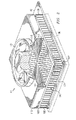
図1は、ポータブルコンピュータ10である装置の概略部分斜視図であり、本発明の態様を具体化した例である。ポータブルコンピュータ10は、ハウジング12とリッド13とを有する。リッド13は、図1に示す開口位置とこのリッドがハウジング12の上面に近接する閉口位置との間で動くように、ハウジング12上に枢軸的に支持される。リッド13は、ポータブルコンピュータに通常使用されるタイプの液晶パネル17(LCD)を有する。
(Detailed Description of the Invention)
FIG. 1 is a schematic partial perspective view of an apparatus that is a
複数の手動制御可能キー18をハウジング12の上部上に設け、これは、コンピュータのキーボードを集約的に規定する。開示したこの実施例において、キーボードは、工業的に標準化された構造に適合するが、代替的にその他の構造であってもよい。ハウジング12の上部壁は、その中央位置に、複数の開口部21を有し、そのそれぞれは、ハウジング12の上部壁を介して延びている。開口部21は、吸気ポートとして機能する。また、ハウジング12は、最も近接した右側壁の端部に、開口部22のクラスターを有し、これは、排出ポートとして集約的に機能する。さらに、ハウジング12の左側壁には、リッド13から離れた端部の近傍で、開口部23のクラスターを有し、これは、さらなる排出ポートとして集約的に機能する。
A plurality of manually
回路基板31は、ハウジング12内に設けられる。回路基板31は、その上に多数の部材を有しているが、これらの部材は、明確に説明するために、図1には全ては示していない。特に、図1は、3つの部材36、37、38のみを示す。集積回路36は、高性能のプロセッサを有しており、これは、本実施例では、公知の装置であって、カリフォルニア州、Santa Claraのインテル社から登録商標PENTIUM(登録商標)の下、市販で入手可能である。しかしながら、本発明は、幅広い集積回路に適合可能であり、これには、他のタイプのプロセッサを含む。
The
冷却組立体41は、集積回路36の上部上に取り付けられ、これと熱連通する。回路基板31は、熱伝導性エポキシ又は集積回路36と回路基板31との間の熱の流動を促進するその他の種々の最適な材料を用いて、集積回路36上に取り付けられてもよい。冷却組立体41の内部構造は、以下に述べる。回路基板31は、熱伝導性を有する外部突出タブ42を有し、その目的は以下に述べる。
The cooling assembly 41 is mounted on the top of the integrated
冷却組立体41は、開口部21で規定された排出ポートを介してハウジング12内に空気を吸気し、これを43として概略的に示す。この気流は、冷却組立体41を通り、冷却組立体41からの熱はこの気流に移行される。この気流のそれぞれの部分は、冷却組立体41から種々の異なる水平方向へと脱出し、その後、開口部22又は開口部23で規定される排出ポートに向かって或いはこれら排出ポートを介して移動する。この気流は、冷却組立体41から排出ポートへと、複数の異なる流路に沿って移動する。これら種々の流路の数例を、図1では、破線45乃至49で示す。空気は、冷却組立体41から上記の2つの排出ポートを規定する開口部23及び開口部23へと流れるので、この空気は、移動し、且つ、プロセッサ以外の、部材37及び部材38を含む部材及び図1には特に示していない部材から熱を奪う。
The cooling assembly 41 draws air into the
冷却組立体41から排出ポートへの気流のパターンは、排出ポートの数に依存し、且つ、排出ポートが配置されている位置に依存する。さらに、2つ以上の排出ポートが配置される場合、排出ポートの相対的な寸法は、各ポートの寸法がこれらポートを規定する開口部全ての集約的な寸法である場合、気流のパターンに影響を与える。例えば、1つの排出ポートにおける開口部の集約的寸法が他の排出ポートにおける開口部の集約的寸法を超える場合、前者のポートよりも後者のポートを介してより多くの空気が流動する。このことを念頭におくと、回路基板31上に設けられた回路においてホットスポットを同定することが可能であり、各排出ポートの位置及び効果的な寸法は、それぞれ同定されたホットスポットを通過する空気の量がその他よりも多い気流パターンを得るように選択されてもよく。
The pattern of airflow from the cooling assembly 41 to the exhaust port depends on the number of exhaust ports and on the position where the exhaust ports are arranged. In addition, when more than one exhaust port is deployed, the relative dimensions of the exhaust ports will affect the airflow pattern if the dimensions of each port are the aggregate dimensions of all the openings that define these ports. give. For example, if the aggregate size of the opening in one exhaust port exceeds the aggregate size of the opening in the other exhaust port, more air will flow through the latter port than the former port. With this in mind, it is possible to identify hot spots in the circuit provided on the
集積回路37は、その上面に取り付けられた熱伝導金属プレート56を有し、熱伝導金属プレート56と集積回路37とは熱連通する。図1の実施例において、熱伝導金属プレート56は、熱伝導性エポキシ樹脂を用いて集積回路37に固定されるが、種々のその他の適切な手法でこの固定を代替的に行ってもよい。公知のタイプの熱パイプ58は、熱伝導金属プレート56にハンダ付けされた一端を有し、他端は、冷却組立体41の外部突出タブ42にハンダ付けされる。代替的に、熱パイプ58は、その他種々の適切な手法で熱伝導金属プレート56及び外部突出タブ42に熱結合されてもよく、この手法は、例えば、熱電動性エポキシ樹脂を用いたり、熱パイプ58の端部の周囲をクリンプされ得る金属部品を熱伝導金属プレート56及び外部突出タブ42に設けることによる方法であってもよい。さらに別の代替例のように、ハウジング12を薄くするため、冷却装置41は、プロセッサ集積回路36の近傍の位置に、回路基板31上に取り付けられてもよく、例えば56で示されるプレートを、プロセッサ集積回路36上に設けてもよく、且つ、熱パイプ58は、プロセッサ集積回路上のプレートから冷却装置41へと伸びていてもよい。
The integrated circuit 37 has a heat conducting metal plate 56 attached to the upper surface thereof, and the heat conducting metal plate 56 and the integrated circuit 37 are in thermal communication. In the embodiment of FIG. 1, the thermally conductive metal plate 56 is secured to the integrated circuit 37 using a thermally conductive epoxy resin, but this securing may alternatively be accomplished in a variety of other suitable ways. A known type of
集積回路38は、その上面上に取り付けられたヒートシンク61を有し、ヒートシンク61と集積回路38とは熱連通する。図1の実施例において、ヒートシンク61は、熱伝導性エポキシ樹脂を用いて集積回路38に固定されるが、その他の種々の適切な手法で一定の場所に代替的に固定されてもよい。ヒートシンク61は、アルミニウムやアルミニウムを主とする金属合金などの金属製であって、垂直上方に延びる突起のアレイ状のベースを有する。空気がパス45に沿って冷却組立体41から開口部23で規定された排出ポートへと移動するので、空気は、ヒートシンク61を超え、且つ、その突起を介して流動する。集積回路38で発生した熱は、ヒートシンク61へと移動し、その後、ヒートシンク61からパス45に沿って流動する。ヒートシンク61は、ヒートシンク61を有さず熱を集積回路38からエアーフローへと直接移動させる必要がある場合よりも低い温度で、集積回路38からエアーフロー45へと熱を移動させる。
The integrated circuit 38 has a
ハウジング12内に壁又は羽根63を設け、羽根63は、回路基板31とハウジング12の上部壁の下部側面との間を垂直的に延びている。本実施例において、羽根63は、ハウジングの上部壁との一体的な部分であって、その上部壁から下方に突出する。しかしながら、羽根63は、物理的に分離していてもよく、且つ、上部壁上又は回路基板31上に取り付けられてもよい。羽根63は、冷却組立体41から開口部23で規定された排出ポートへと流れる空気のパターンに影響を与える。所定の回路基板上の1つ以上のホットスポットが同定されると、ホットスポットの少なくとも1つを通過する気流の量を増加させるように補助する寸法、配向及び位置に、符号63で示したタイプの1つ以上の羽根を加えてもよい。
A wall or blade 63 is provided in the
図2は、拡大して冷却組立体41を示す概略部分斜視図であって、冷却組立体41に取り付けられる集積回路36を破線で示す。冷却組立体41は、アルミニウム又はアルミニウム合金製の底プレート101を有し、このプレートは、外部突出タブ42として機能するように、その側面の一つから外部に延びる内部突起以外は、略正方形である。上プレート103は、アルミニウム又はアルミニウム合金製であって、底プレート101のサイズと一致する四角形を有する。上プレート103は、底プレート101と上プレート103のそれぞれの角に配置された4つの垂直ポストで、底プレート101の若干上方に支持される。なお、これらポストのうち3つのポストは、図2において106乃至108で示す。これらポストは、鋳造、蝋着又はその他の種々の適切な手法で、底プレート101と上プレート103とに固定される。上プレート103は、垂直に延びる正方形開口部111を有する。正方形開口部111は、上プレート103の寸法よりも若干小さく、上プレート103が効果的な四角形フレームとなる。
FIG. 2 is a schematic partial perspective view showing the cooling assembly 41 on an enlarged scale, and an
若干の垂直の高さを有するプレナム116は、アルミニウム又はアルミニウム合金であり、その上面は、上プレート103の正方形に一致する寸法の正方形を有する。代替的に、プレナムは、ポリカーボネートなどのその他の種々の適切な材料で製造されてもよい。プレナム116は、例えば、鋳造、蝋着、熱伝導性エポキシ樹脂、公知のタイプの熱伝導性菱面テープ又はその他種々の適切な手法により、上プレート103に強固に固定される。プレナム116の底部壁は、正方形開口部117を有し、これは、上プレート103に設けられた正方形開口部111に配列され且つこれと同様の寸法を有する。
The
プレナム116の上部壁は、円形開口部118を有する。薄型のファン121は、比較的低い垂直高を有し、円形開口部118よりも幾分大きな径を有し、且つ、円形開口部118の上部壁に同軸に配列されるように、プレナム116の上部壁に強固に固定される。ワイヤー(図示せず)を介して電流がファン121に供給されると、プレナム116を介して空気を下方に流動させる。
The top wall of the
冷却組立体41は、上プレート103と底プレート101との間に、熱伝導性フィンストック141を有する。フィンストック141は、公知の種類の熱伝導性エポキシ樹脂で、底プレート101に固定される。なお、これは、その他の種々の方法、例えば、鋳造や蝋着などにより、底プレート101に代替的に固定されてもよい。フィンストック141は、図3及び図4を参照して以下により詳細に述べる。
The cooling assembly 41 has a thermally
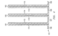
この点、図3は、フィンストック141の概略上面図を示し、図4は、フィンストック141の一部の概略部分側方断面図を示す。図3を参照すると、フィンストック141は、4つの異なる部品151乃至154を有し、それぞれは、上部から見ると略正方形であり、その外角だけは、若干の凹部を有する。なお、この凹部は、上記の4つの支持ポストのそれぞれのクリアランスを提供し、これらポストの4つは、図2において、106乃至108で示す。部品151乃至154の対向する内角は、図3の平面から垂直に延びる垂直軸158に沿って配置された共通位置にすべて配置される。ファン121(図2)及びプレナムの上部へ基の円形開口部118は、この熱パイプ58に両方とも同心である(図3)。
In this regard, FIG. 3 shows a schematic top view of the
フィンストック141の部品151乃至154は、全て互いに同一であるので、以下、部品151についてのみ説明する。図3を参照すると、部品151は、略水平ベース部161と、略水平ベース部161から垂直上方にそれぞれ延びる複数の平行フィンとを有する。部品151は、アルミニウム合金の薄シート状製であって、この実施例では、先行技術におけるアルミニウム3003などの公知の合金であって、典型的には、1.2%のマグネシウムを含有し、その他の部分は、アルミニウムを含有するが、この合金の定義では、1〜1.5%のマグネシウム、0.6%以下のシリコン、0.7%以下の鉄、0.2%以下の銅、0.1%以下の亜鉛及びその他の要素は0.05%以下であってもよく、これら全ての要素は、アルミニウム及びマグネシウムを除いて、全量で、0.15%以下である。
Since the
部品151として機能するこのアルミニウム合金製シートは、図4に示すような断面形状を有する。しかしながら、部品151は、熱を良好に導電するその他種々の適切な材料製であってもよい。この点、この湾曲したアルミニウム製シートは、複数の垂直伸張部を有し、そのそれぞれは、側壁として機能し、これらのうち6つは、171乃至176でこの図に示す。これらの側壁は、ペアで配列され、それぞれのペアの側壁は、互いに近接し、他のペアの側壁と分離されて配置される。この湾曲したアルミニウムシートは、複数の上壁部を有し、そのそれぞれは、個々のペアの側壁の上端部間に延び、これら上壁部の3つを181乃至183で示す。このアルミニウムシートは、さらに、複数の底壁部を有し、そのそれぞれは、異なるペアに存在する2つの側壁の低端部間に延び、これらの底壁部の4つを186乃至189で示す。
The aluminum alloy sheet functioning as the
186乃至189で示した部分を含む底壁部は、部品151の略水平ベース部161(図3)を集約的に規定する。側壁のペア171及び172並びにその上壁部181は、フィン162(図3)を規定し、側壁のペア173及び174並びにその上壁部182は、他のフィン162を規定し、且つ、側壁のペア175及び176並びにその上壁部183は、さらに別のフィン162を規定する。各ペアの側壁は、互いに十分近接して配置され、これらの間を空気が有意に流動するのに十分な余地はない。従って、気流の一部が各ペアの側壁間の領域に進入可能とするようにこの上部壁に開口部を形成する必要がない。部品151乃至154は、図4に示す形状を有するように大型のアルミニウム製シートを折り曲げて製造されてもよく、その後、研磨性水ジェットでこの大型のシートから部品151乃至154を切断する。
The bottom wall portion including the portions denoted by
再び図3を参照すると、部品151乃至154は、その中心に略配置され且つ軸158の略円周方向にその部分を対角線上に伸びる1つのフィンをそれぞれ有する。各部品151乃至154上の他のフィンのそれぞれは、近接する部品151乃至154上の個々のフィンの内端部を係合する内端部を有する。この実施例において、フィンストック141のフィン162は、約0.006インチの厚み、0.25インチの垂直高及び1インチ当たり18フィンのピッチを有する。
Referring again to FIG. 3, the
図2を参照すると、動作時、集積回路36内の回路で発生した熱は、集積回路36から冷却装置41の底プレート101へと上方に伝播し、その後、底プレート101からフィンストック141の部品151乃至154へと伝播する。ファン121は、吸入ポートを規定する開口部22を介して空気をハウジング12内に吸引し、この吸気をプレナム116及び上プレート103の正方形開口部111を介して下方へと流動させる。
Referring to FIG. 2, in operation, heat generated in the circuits in the
空気のこの下方への流動がフィンストック141に到達すると、上記の4つのフィンストックの部品151乃至154のフィンは、この気流を部分に分割し、近接するフィン間で4つの異なる水平方向へと再度流動させる。なお、図3において、これら気流は、フィンストック141の周囲に記載した矢印で概略的に示す。図3に記載した矢印の相対的な長さは、この周辺に沿った複数の位置のそれぞれにおいて、フィンストック141に存在する空気の容量及び速度を概略的に示す。気流を、4つの異なる方向に再度それぞれ流動させる部分に分割することにより、フィンストック141は、冷却装置31に非常に低い圧力低下のみをもたらし、空気の流動をより速い率で促進する。この低い圧力低下により、ファン121は、最小限の作動で所望する気流を駆動させ得ることになり、これにより、ファンで消費されるバッテリーの電力量を最小限とすることができ、このことは、ポータブルコンピュータにとって常に利点である。さらに、この低い圧力低下は、気流の可聴性ノイズを最小限とし、且つ、良好な冷却を促進する。
When this downward flow of air reaches the
この実施例において、冷却組立体41は、約15℃温度上昇させる2×2インチの面積における20ワットの熱を分散可能である。この冷却組立体の全体的な厚みは、約0.4インチ未満である。上記のファンの電力消費量は、約2〜3ワットのみであって、このうち、約0.7ワットは、プロセッサを有する回路部材36の冷却に関連し、残りは、冷却組立体41から排出ポートを規定する開口部22及び開口部23への気流を制御することに包含される追加の圧力低下に関連する。回路基板31を介した気流の容積は、一分間当たり3.53ft3であり、その圧力低下は、水の0.029インチである。
In this embodiment, the cooling assembly 41 can dissipate 20 watts of heat in an area of 2 × 2 inches that raises the temperature by about 15 ° C. The overall thickness of the cooling assembly is less than about 0.4 inches. The fan consumes only about 2 to 3 watts, of which about 0.7 watts is related to cooling the
図5は、図3と同様の概略上面図であるが、図4のフィンストック141の代替実施例であるフィンストック241を示す。フィンストック241は、フィンストック141とほぼ同様であるが、下記の点で異なる。特に、フィンストック241は、4つの部品251乃至254を有し、これらは、部品151乃至154とほぼ同様である。主に異なる点は、上面において、部品251乃至254は、正方形ではなく、略直角三角形の形状をそれぞれ有する点である。これら三角形部品における90°の頂点は、垂直軸158に沿って配置された共通位置に全て位置している。各部品の他の2つの角は、若干円形の凹部を有し、上記の4つのコーナーポストの個々の1つに関するクリアランスを提供する。
FIG. 5 is a schematic top view similar to FIG. 3, but showing a
動作時、フィンストック241は、フィンストック141と同様の様式にて、4つの水平方向に流動する位置における垂直的な気流を分割し且つ再指向する。さらに、フィンストック241は、フィンストック141の低い圧力低下と比較して、低い圧力低下性を有する。
In operation,
図3及び図4を参照して上述したように、フィンストック141は、4つの異なる部品151乃至154として製作され、そのそれぞれは、アルミニウム製の湾曲シートである。同様に、図5に示すフィンストック241の部品251乃至254も、それぞれ、アルミニウム製の湾曲シートである。フィンストック141及びフィンストック141に代えて、熱を良好に伝導する種々の他の材料で製造されたフィンストックを使用することも代替的に可能である。この点、図6では、符号341で示す、射出成形したフィンストックの概略部分側方断面図を示す。
As described above with reference to FIGS. 3 and 4, the
フィンストック341は、例えば、熱伝導性液晶ポリマー(LCP)又は熱伝導性ポリエチレンサルファイド(PPS)であるベースポリマーを有する材料などの熱伝導性成形材料で射出成形される。例えば、適切なベースポリマーは、LCP製品であるCOOLPOLY E2並びにPPS製品であるCOOLPOLY RB020及びCOOLPOLY RS012などの、Rhode Island、WarwickにあるCool Polymer Inc.社製の登録商標COOLPOLY製品が市販で入手可能である。フィンストック341は、図1乃至5の実施例のような種々の分離したセクションとは異なり、単一射出成形部品である。射出成形に対する代替例として、フィンストック341をレジントランスファーモールディング(resin transfer molding)で形成してもよいことは認識されるであろう。
The
図示しないが、さらなる代替例として、フィンストックを成形する場合(例えば、符号341で示すように成形する場合)、上プレート103を任意で削除してもよく、プレナム116は、例えば、適切な公知のエポキシ系接着剤を用いて、フィンストック341のフィンの上部に直接固定されてもよい。この場合、上記の4つの支持ポストを任意で削除することも可能である(なお、これら4つのポストのうち3つは、106乃至108で示す)。更に別の代替例として、成形フィンストックは、成形フィンストック341と一体化した部品として上プレート103を製造してもよく、且つ、プレナム116をその一体化上プレートに直接固定してもよい点を除いて、図6で符号361として示すのと同様であってもよい。
Although not shown, as a further alternative, when forming fin stock (eg, as shown by reference numeral 341), the
図7は、図2と同様の概略部分斜視図であるが、図2の回路基板31の代替実施例である冷却組立体441を示す。冷却組立体441は、下述する点で相違する以外、冷却組立体41と同一である。特に、回路基板31のフィンストック141は、冷却組立体441では削除されており、多孔性材料の略方形ブロック444をその場所に設けている。ブロック444は、底プレート101から上プレート103へと垂直方向に延び、鋳造、蝋着、熱伝導性エポキシ樹脂又はその他の種々の適切な方法で、底プレート101に物理的且つ熱的に固定される。
FIG. 7 is a schematic partial perspective view similar to FIG. 2, but showing a
多孔性ブロック444は、熱伝導性のオープンセル型焼結(open−cell sintered)材料製であるが、熱伝導性の多孔性オープンセル型発泡材料であってもよい。この実施例において、ブロック444に使用される焼結又は発泡多孔性材料は、アルミニウムであるが、他の種々の適切な熱伝導性材料であってもよい。多孔性ブロック444は、比較的安価である。ファン121からの下方気流は、ブロック444の中央部分に進入し、その後、種々の異なる円周方向へとブロック444を介して水平的且つ外側に流動する。
The
上述したように、図6のフィンストック341は、合成材料の射出成形部品である。別の代替例として、このフィンストックは、ダイキャスト亜鉛合金などのキャスティングや鋳造に適合性を有するその他の種々の熱伝導性材料製であってもよい。この点、図8は、亜鉛合金で製造されたダイキャスト部品であるフィンストック541の概略上面図であって、図2及び図3のフィンストック141の代替実施例であり、図2の冷却組立体41におけるフィンストック141に置換されてもよい。フィンストック541は、その水平方向において、約2×2インチの寸法を有し、そのベースプレートは、約0.05インチ厚であり、そのフィンは約0.25インチ高である。また、1インチ当たり16フィンを有し、このフィンは、円形ティップを有する。
As described above, the
このフィンは、上記のティップからベースへと厚みが増加しており、ティップの近傍では約0.01インチ厚であり、ベース近傍では約0.025インチ厚である。フィンの近接するそれぞれのペア間で、ベースの上面は、曲線となるように、若干円形とされる。フィンストック541に使用する亜鉛合金は、亜鉛ダイキャスト合金3として一般的に知られる合金であって、3.5〜4.3%のアルミニウム、最大で0.25%の銅、0.02〜0.05%のマグネシウム、最大で0.1%の鉄、最大で0.005%の鉛、最大で0.004%のカドミウム及び最大で0.003%のスズを含有し、バランスは、亜鉛である。もちろん、これらフィンストック541にて上述した特定の寸法及び特定の合金は、例示であって、その寸法及び材料は、本発明の範囲から逸脱することなく、種々変更可能であることは認識されるであろう。
The fins increase in thickness from the tip to the base and are approximately 0.01 inches thick near the tip and approximately 0.025 inches thick near the base. Between each adjacent pair of fins, the upper surface of the base is slightly circular so as to be curved. The zinc alloy used for the
本発明は、複数の技術的利点を提供する。かかる1つの技術的利点は、プロセッサなどの回路部材用の薄型の冷却組立体をポータブルコンピュータ内に設けることが出来る点である。1つの有利な構成において、冷却組立体は、ハウジングの外側から吸引された強制気流に影響を及ぼし、この冷却組立体41からの気流は、他の熱分散部材の冷却を促進するように、ハウジング内でルーティングされる。この気流のルーティングは、ハウジングに存在する気流を介して複数の排出ポートを選択し且つかかる排出ポートのそれぞれの位置及び/又は効果的な寸法を選択することを含む技術により、促進される。また、気流のルーティングは、ハウジング内に戦略的に配置された羽根を使用して促進されてもよい。 The present invention provides several technical advantages. One such technical advantage is that a thin cooling assembly for circuit components such as processors can be provided in a portable computer. In one advantageous configuration, the cooling assembly affects the forced airflow drawn from the outside of the housing, and the airflow from the cooling assembly 41 facilitates cooling of the other heat spreading members. Routed within. This routing of airflow is facilitated by techniques that include selecting a plurality of exhaust ports via the airflow present in the housing and selecting the location and / or effective dimensions of each such exhaust port. Airflow routing may also be facilitated using vanes strategically located within the housing.
関連する利点は、その部材からの熱の、冷却組立体から排出ポートに移動する気流への効果的な移行を促進するため、部材が、局所のフィン型ヒートシンクを有する場合に認識される。更に別の利点は、例えば熱分散部材から冷却組立体への熱の移行を補助するためハウジング内にヒートパイプを設ける場合に認識される。かかる技術を使用すると、ポータブルコンピュータは、比較的薄型で軽量とすることができ、最も高速で制御するプロセッサを有することが可能である一方で最小限の電力を消費する構成を採用することで効果的な冷却性を得ることができる。 A related advantage is recognized when the member has a local fin-type heat sink to facilitate the effective transfer of heat from that member to the airflow moving from the cooling assembly to the exhaust port. Yet another advantage is recognized when a heat pipe is provided in the housing, for example, to assist in the transfer of heat from the heat spreading member to the cooling assembly. Using such technology, portable computers can be relatively thin and lightweight, and can have the most fast control processor while having the least power consumption configuration. Cooling performance can be obtained.
有利の構成において、冷却組立体は、熱導電部を介して複数の有意に異なる方向へと流動するように分割される強制気流を使用する。かかる熱伝導部の1つは、多孔性材料のブロック体である。異なる熱伝導部は、気流を多数の方向へと流動する部分に分割するフィンストックである。気流の分割により、低い圧力低下のみが発生し、これは、冷却組立体に関して、低い電力消費と可聴性ノイズを最小限とすることを促進する。さらに、比較的低重量であるが滞留性熱移行を高い程度で達成する大表面領域を提供するフィンストックを用いると効果的である。他の利点は、ポータブルコンピュータに使用する際コンピュータのハウジングを比較的薄型とし得る冷却組立体が非常に薄型であっても、冷却組立体がこれら利点を達成する点である。 In an advantageous configuration, the cooling assembly uses a forced air stream that is split to flow in a plurality of significantly different directions through the thermal conductor. One such heat conducting part is a block of porous material. The different heat conducting parts are fin stocks that divide the air stream into parts that flow in multiple directions. Due to the split of the airflow, only a low pressure drop occurs, which helps to minimize low power consumption and audible noise for the cooling assembly. In addition, it is advantageous to use fin stock that provides a large surface area that is relatively low weight but that achieves a high degree of stagnant heat transfer. Another advantage is that the cooling assembly achieves these advantages even when the cooling assembly, which can be made relatively thin when used in a portable computer, is very thin.
選択した実施例について詳細の図示し且つ説明してきたが、請求項で規定した本発明の概念及び範囲を逸脱することなく種々の置換及び変更が可能であることは理解されるであろう。 Although selected embodiments have been shown and described in detail, it will be understood that various substitutions and modifications can be made without departing from the spirit and scope of the invention as defined in the claims.
Claims (24)
該ハウジング内に配置され部材を有する回路;及び
前記部材に熱結合された温度調節装置;
を有する、ポータブルコンピュータを備える装置であって、
前記温度調節装置は:
軸に略平行な方向に面し前記部材に熱結合された側面を有する熱伝導部;及び
前記部材と逆の前記熱伝導部の側面上に配置され前記軸に沿って前記熱伝導部へと流体流動させ得る流体供給部であって、
前記熱伝導部は、前記流体流動を前記軸に垂直な平面に略平行な方向に前記熱伝導部を介してそれぞれ流動する複数の流動部分に分割させ、
前記流動部分は、前記熱伝導部の周辺の実質部分に沿って配置された個々の複数の位置において前記熱伝導部に存在する、流体供給部;
を有することを特徴とする装置。 housing;
A circuit having a member disposed within the housing; and a temperature control device thermally coupled to the member;
A device comprising a portable computer comprising:
The temperature control device is:
A heat-conducting portion having a side surface facing in a direction substantially parallel to the axis and thermally coupled to the member; A fluid supply section capable of fluid flow,
The heat conduction part divides the fluid flow into a plurality of flow parts each flowing through the heat conduction part in a direction substantially parallel to a plane perpendicular to the axis,
The fluid supply portion is present in the heat conducting portion at a plurality of individual positions arranged along a substantial portion of the periphery of the heat conducting portion;
A device characterized by comprising:
略対向し前記軸にそれぞれ略平行な、第1側面と第2側面とを有し、前記第1側面は、前記部材に熱結合された前記側面である、ベース部;及び
該ベース部の前記第2側面から略前記第2方向へと外側に突出する複数のフィンであって、
該フィンは、前記軸周辺に角的に分布する少なくとも3つのグループに配列され、
該グループにおける前記フィンは、互いに略平行に延び、
前記グループのそれぞれは、前記軸の略円周方向に延びる少なくとも1つの前記フィンを有し、
前記流動部分は、前記グループの数と同数であり、
前記流動部分は、前記グループのそれぞれのフィン間及び該フィンに平行に軸から離れて流動する、複数のフィン;
を有することを特徴とする請求項2に記載の装置。 The heat conducting part is:
A base portion having a first side surface and a second side surface that are substantially opposite and substantially parallel to the axis, wherein the first side surface is the side surface thermally coupled to the member; and the base portion A plurality of fins projecting outward from the second side surface substantially in the second direction,
The fins are arranged in at least three groups angularly distributed around the axis;
The fins in the group extend substantially parallel to each other;
Each of the groups has at least one fin extending in a generally circumferential direction of the shaft;
The flow portion is the same as the number of the groups,
The flow portion includes a plurality of fins that flow away from an axis between and parallel to the fins of the group;
The apparatus of claim 2, comprising:
前記グループの2つのフィンは、前記軸に垂直な第2ラインに略平行に延び、
前記グループの他の2つのフィンは、前記軸及び前記第1ラインのそれぞれに垂直な第2ラインに略平行に延びている、
ことを特徴とする請求項3に記載の装置。 The device has four of the groups of fins,
The two fins of the group extend substantially parallel to a second line perpendicular to the axis;
The other two fins of the group extend substantially parallel to a second line perpendicular to each of the axis and the first line;
The apparatus according to claim 3.
前記流体供給部は、気流を前記ハウジングの外側から前記第1ポートを介して前記ハウジングへと吸入する、前記第1ポートと流体連通し、
前記流体流動は、前記気流を含み、
前記流動部分の空気の少なくとも一部は、前記熱伝導部を離れた後、前記第1ポートを介して前記ハウジングを脱出する、
ことを特徴とする請求項1に記載の装置。 The housing has a first port and a second port extending therethrough,
The fluid supply section is in fluid communication with the first port for sucking an airflow from the outside of the housing into the housing via the first port;
The fluid flow includes the air flow;
At least a portion of the air in the flow portion escapes the housing through the first port after leaving the heat conducting portion;
The apparatus according to claim 1.
前記回路は、前記熱伝導部から前記第2ポートへと流動する空気の通路に沿って配置された追加部材を有する;
ことを特徴とする請求項5に記載の装置。 The second port is disposed away from the heat conducting portion; and the circuit includes an additional member disposed along a passage of air flowing from the heat conducting portion to the second port;
The apparatus according to claim 5.
前記流動部分の空気の一部は、前記熱伝導部を離れた後、前記ハウジングから前記第3ポートへと移動する、
ことを特徴とする請求項5に記載の装置。 The housing has a third port extending therethrough, spaced from the second port;
A part of the air in the flow part moves from the housing to the third port after leaving the heat conducting part.
The apparatus according to claim 5.
前記第2ポート及び前記第3ポートは、前記熱伝導部からそれぞれ離れ且つ互いに離れて配置され、
前記流動部分の空気の個々の部分は、前記熱伝導部を離れた後、前記第2ポート及び前記第3ポートを介して前記ハウジングをそれぞれ脱出し;
前記回路は、前記流動部分における空気の個々の部分の個々の通路に沿ってそれぞれ配置された2つの追加部材を有する
ことを特徴とする請求項5に記載の装置。 The housing has a third port therethrough;
The second port and the third port are disposed apart from each other and away from the heat conducting unit,
Individual portions of the air in the flow portion leave the heat transfer portion and then exit the housing through the second port and the third port, respectively;
6. The apparatus of claim 5, wherein the circuit comprises two additional members, each disposed along an individual passage of an individual portion of air in the flow portion.
当該装置は、前記ハウジング内に配置された熱パイプを有し、
該熱パイプは、前記追加部材に熱結合された第1部分と、前記第1部分から分離した配置され前記熱伝導部に熱結合された第2部分とを有する、
ことを特徴とする請求項1に記載の装置。 The circuit has an additional member;
The apparatus has a heat pipe disposed in the housing,
The heat pipe includes a first portion thermally coupled to the additional member, and a second portion disposed separately from the first portion and thermally coupled to the heat conducting unit.
The apparatus according to claim 1.
温度調節装置を前記部材に熱結合するステップであって、前記温度調節装置は、軸に略平行な方向に面し前記部材に熱結合された側面を有する熱伝導部を有する、ステップ;及び
前記軸に沿って前記部材と逆の前記熱伝導部の側面へと流体流動を起こすステップであって、前記熱伝導部は、前記流体流動を、前記軸に垂直な平面に略平行な方向に複数の流動部分に分割させ、該流動部分は、前記熱伝導部の周辺の実質部分に沿って配置された個々の複数の位置において前記熱伝導部に存在する、ステップ;
を有することを特徴とする方法。 A method of cooling a portable computer including a housing having a circuit with members therein.
Thermally coupling a temperature regulating device to the member, the temperature regulating device comprising a heat conducting portion having a side surface facing in a direction substantially parallel to an axis and thermally coupled to the member; and A step of causing fluid flow along an axis to a side surface of the heat conducting unit opposite to the member, wherein the heat conducting unit performs a plurality of fluid flows in a direction substantially parallel to a plane perpendicular to the axis. The flow portion is present in the heat conducting portion at a plurality of individual positions disposed along a substantial portion of the periphery of the heat conducting portion;
A method characterized by comprising:
前記ベース部の前記第2側面から略前記第2方向へと外側に突出する複数のフィンを有するように、前記熱伝導部を構成するステップであって、前記フィンは、前記軸の周囲に角的に分布された少なくとも3つのグループに配列され、
前記グループのそれぞれにおけるフィンは、互いに略平行に延び、
前記グループのそれぞれは、前記軸の略円周方向に延びる少なくとも1つの前記フィンを有し、
前記流動部分は、前記グループの数と同数であり、
前記流動部分のそれぞれは、前記グループのそれぞれのフィンの間及び該フィンに平行に前記軸から離れて流動する、ステップ;
を有することを特徴とする請求項16に記載の方法。 Configuring the heat conducting portion to have a base portion with a first side and a second side facing each other in a first direction and a second direction substantially opposite and substantially parallel to the axis; The first side surface is the side surface thermally coupled to the member; a step; and a plurality of fins protruding outward from the second side surface of the base portion substantially in the second direction, Configuring the heat conducting part, wherein the fins are arranged in at least three groups angularly distributed around the axis;
The fins in each of the groups extend substantially parallel to each other;
Each of the groups has at least one fin extending in a generally circumferential direction of the shaft;
The flow portion is the same as the number of the groups,
Each of the flow portions flows away from the axis between and parallel to the fins of the group;
The method of claim 16, comprising:
該グループの2つのグループのフィンは、前記軸に垂直な第1ラインに略平行に延び、
該グループの他の2つのグループのフィンは、前記軸及び前記第2ラインのそれぞれに垂直な第2ラインに略平行に延びる、
ことを特徴とする請求項17に記載の方法。 The method comprises the step of grouping the fins into four groups;
Two groups of fins of the group extend substantially parallel to a first line perpendicular to the axis;
The fins of the other two groups of the group extend substantially parallel to a second line perpendicular to each of the axis and the second line;
The method according to claim 17, wherein:
気流を前記ハウジングの外部から前記第1ポートを介し前記ハウジング内へと吸入するステップであって、前記流体流動は、前記気流を有する、ステップ;及び
前記流動部分の空気の少なくとも一部を、該一部が前記熱伝導部を離れた後、前記第2ポートを介して前記ハウジングを脱出させるステップ;
を有することを特徴とする請求項15に記載の方法。 Configuring the housing to have a first port and a second port extending through the housing;
Sucking an airflow from outside the housing into the housing through the first port, wherein the fluid flow comprises the airflow; and at least a portion of the air in the flow portion, Allowing the housing to escape through the second port after a portion has left the heat transfer section;
The method of claim 15, comprising:
当該方法は、前記熱伝導部から前記第2ポートに流動する空気のパスに沿って前記回路の追加部材を配置するステップを有する、
ことを特徴とする請求項19に記載の方法。 The step of configuring includes the step of providing the second port at a position away from the heat conducting unit,
The method includes disposing an additional member of the circuit along a path of air flowing from the heat conducting portion to the second port.
20. A method according to claim 19, wherein:
当該方法は、前記流動部分における空気の各一部を、該一部が前記熱伝導部を離れた後、前記第2ポートと前記第3ポートとを介して前記ハウジングをそれぞれ脱出させるステップ;
を有することを特徴とする請求項19に記載の方法。 The step of configuring includes a step of providing a third port through the housing and disposing the second port and the third port at individual positions disposed away from each other from the heat conducting unit. Have
The method includes causing each part of the air in the flow part to escape from the housing via the second port and the third port after the part leaves the heat conducting part;
20. The method of claim 19, comprising:
前記熱パイプの第1部分から離れて配置された前記熱パイプの第2部分を、前記熱伝導部に熱結合するステップ;
を有することを特徴とする請求項15に記載の方法。 Thermally coupling a first portion of the heat pipe to an additional member of the circuit; and thermally coupling a second portion of the heat pipe disposed remotely from the first portion of the heat pipe to the heat conducting portion. ;
The method of claim 15, comprising:
Applications Claiming Priority (2)
| Application Number | Priority Date | Filing Date | Title |
|---|---|---|---|
| US10/164,522 US6972950B1 (en) | 2002-06-06 | 2002-06-06 | Method and apparatus for cooling a portable computer |
| PCT/US2003/017953 WO2003105224A2 (en) | 2002-06-06 | 2003-06-05 | Method and apparatus for cooling a portable computer |
Publications (2)
| Publication Number | Publication Date |
|---|---|
| JP2006517308A true JP2006517308A (en) | 2006-07-20 |
| JP2006517308A5 JP2006517308A5 (en) | 2007-02-08 |
Family
ID=29732024
Family Applications (1)
| Application Number | Title | Priority Date | Filing Date |
|---|---|---|---|
| JP2004512194A Pending JP2006517308A (en) | 2002-06-06 | 2003-06-05 | Method and apparatus for cooling portable computer |
Country Status (7)
| Country | Link |
|---|---|
| US (2) | US6972950B1 (en) |
| EP (1) | EP1543557B1 (en) |
| JP (1) | JP2006517308A (en) |
| CN (1) | CN100397631C (en) |
| AU (1) | AU2003247504B2 (en) |
| CA (1) | CA2488626A1 (en) |
| WO (1) | WO2003105224A2 (en) |
Families Citing this family (34)
| Publication number | Priority date | Publication date | Assignee | Title |
|---|---|---|---|---|
| US7046515B1 (en) * | 2002-06-06 | 2006-05-16 | Raytheon Company | Method and apparatus for cooling a circuit component |
| US20040252455A1 (en) * | 2003-03-20 | 2004-12-16 | Kuo Yi-Lung | Computer cooling system with fan |
| TWI260484B (en) * | 2003-08-12 | 2006-08-21 | Asustek Comp Inc | Heat sink for power device on computer motherboard |
| TWI251460B (en) * | 2004-01-09 | 2006-03-11 | Delta Electronics Inc | Compound heat sink with multi-directional fins |
| US7331377B1 (en) * | 2004-01-30 | 2008-02-19 | Isothermal Systems Research, Inc. | Diamond foam spray cooling system |
| US8341965B2 (en) * | 2004-06-24 | 2013-01-01 | Raytheon Company | Method and system for cooling |
| ITRM20040166U1 (en) * | 2004-10-25 | 2005-01-25 | Vasco Petruzzi | HIGH PYRAMID CASE OF HEAT DISSIPATION. |
| US7443670B2 (en) * | 2005-01-07 | 2008-10-28 | Intel Corporation | Systems for improved blower fans |
| TWM273940U (en) * | 2005-03-23 | 2005-08-21 | Inventec Corp | Main frame casing for electronic product |
| US20060237168A1 (en) * | 2005-04-21 | 2006-10-26 | Belady Christian L | Air mover with thermally coupled guide vanes |
| TWI259522B (en) * | 2005-08-02 | 2006-08-01 | Quanta Comp Inc | Electronic device |
| US9047066B2 (en) | 2005-09-30 | 2015-06-02 | Intel Corporation | Apparatus and method to efficiently cool a computing device |
| US7317614B2 (en) * | 2005-10-19 | 2008-01-08 | Hewlett-Packard Development Company, L.P. | Computer device cooling system |
| CN100592240C (en) * | 2005-10-28 | 2010-02-24 | 鸿富锦精密工业(深圳)有限公司 | Heat sink and note-book computer with the heat sink |
| JP2007172328A (en) * | 2005-12-22 | 2007-07-05 | Toshiba Corp | Electronic device |
| EP2011377B1 (en) * | 2006-04-27 | 2014-11-19 | NetApp, Inc. | Airflow guides using silicon walls/creating channels for heat control |
| KR101110434B1 (en) * | 2006-05-02 | 2012-02-24 | 엘지전자 주식회사 | Computer cooling device |
| US20080093058A1 (en) * | 2006-10-24 | 2008-04-24 | Jesse Jaejin Kim | Systems and methods for orientation and direction-free cooling of devices |
| US8376032B2 (en) * | 2006-10-24 | 2013-02-19 | Vapro Inc. | Systems and methods for providing two phase cooling |
| US20080174957A1 (en) * | 2007-01-23 | 2008-07-24 | Lev Jeffrey A | Electronic device cooling system |
| US20080237845A1 (en) * | 2007-03-28 | 2008-10-02 | Jesse Jaejin Kim | Systems and methods for removing heat from flip-chip die |
| CN101282629B (en) * | 2007-04-06 | 2010-05-26 | 富准精密工业(深圳)有限公司 | Cooling device |
| US8837139B2 (en) * | 2007-09-29 | 2014-09-16 | Biao Qin | Flat heat pipe radiator and application thereof |
| US7957140B2 (en) * | 2007-12-31 | 2011-06-07 | Intel Corporation | Air mover for device surface cooling |
| US20100012354A1 (en) * | 2008-07-14 | 2010-01-21 | Logan Brook Hedin | Thermally conductive polymer based printed circuit board |
| JP5343574B2 (en) * | 2009-01-20 | 2013-11-13 | トヨタ自動車株式会社 | Brazing method of heat sink |
| CN201569961U (en) * | 2009-02-25 | 2010-09-01 | 仁宝资讯工业(昆山)有限公司 | Portable electronic device and radiating structure thereof |
| JP5238841B2 (en) * | 2011-03-08 | 2013-07-17 | 株式会社東芝 | Electronics |
| JP2014232385A (en) * | 2013-05-28 | 2014-12-11 | ソニー株式会社 | Electronic device |
| US20150084490A1 (en) * | 2013-09-25 | 2015-03-26 | Kabushiki Kaisha Toshiba | Electronic apparatus |
| CN104679183A (en) * | 2013-11-29 | 2015-06-03 | 英业达科技有限公司 | Electronic device |
| US10692798B2 (en) * | 2014-04-10 | 2020-06-23 | Advanced Thermal Solutions, Inc. | Multiple flow entrance heat sink |
| US10506735B2 (en) | 2014-08-25 | 2019-12-10 | Hamilton Sundstrand Corporation | Heat exchange device in directed flow system |
| CN205030031U (en) * | 2015-10-12 | 2016-02-10 | 中磊电子(苏州)有限公司 | Heat conduction plastics radiator and communication device |
Family Cites Families (24)
| Publication number | Priority date | Publication date | Assignee | Title |
|---|---|---|---|---|
| US4715438A (en) | 1986-06-30 | 1987-12-29 | Unisys Corporation | Staggered radial-fin heat sink device for integrated circuit package |
| US4753290A (en) | 1986-07-18 | 1988-06-28 | Unisys Corporation | Reduced-stress heat sink device |
| US4682651A (en) | 1986-09-08 | 1987-07-28 | Burroughs Corporation (Now Unisys Corporation) | Segmented heat sink device |
| US5365400A (en) | 1988-09-09 | 1994-11-15 | Hitachi, Ltd. | Heat sinks and semiconductor cooling device using the heat sinks |
| US5005640A (en) | 1989-06-05 | 1991-04-09 | Mcdonnell Douglas Corporation | Isothermal multi-passage cooler |
| JP3069819B2 (en) | 1992-05-28 | 2000-07-24 | 富士通株式会社 | Heat sink, heat sink fixture used for the heat sink, and portable electronic device using the heat sink |
| US5494098A (en) | 1994-06-17 | 1996-02-27 | Wakefield Engineering, Inc. | Fan driven heat sink |
| US5581443A (en) * | 1994-09-14 | 1996-12-03 | Kabushiki Kaisha Toshiba | Structure for cooling a circuit module having a circuit board and a heat-generating IC chip mounted on the board, and portable electronic apparatus incorporating the structure |
| US5582240A (en) * | 1994-09-19 | 1996-12-10 | Motorola, Inc. | Pneumatically coupled heat sink assembly |
| US5583746A (en) | 1994-12-12 | 1996-12-10 | Tennmax Trading Corp. | Heat sink assembly for a central processing unit of a computer |
| US5694294A (en) * | 1995-01-27 | 1997-12-02 | Hitachi, Ltd. | Portable computer with fan moving air from a first space created between a keyboard and a first circuit board and a second space created between the first circuit board and a second circuit board |
| JP3258198B2 (en) * | 1995-04-28 | 2002-02-18 | 株式会社東芝 | Cooling device for circuit module and portable electronic device having this cooling device |
| TW314223U (en) | 1995-11-06 | 1997-08-21 | Nippon Keiki Works Co Ltd | Cooling radiator |
| US5896917A (en) | 1996-02-22 | 1999-04-27 | Lemont Aircraft Corporation | Active heat sink structure with flow augmenting rings and method for removing heat |
| US5794685A (en) | 1996-12-17 | 1998-08-18 | Hewlett-Packard Company | Heat sink device having radial heat and airflow paths |
| JP4290232B2 (en) | 1997-02-24 | 2009-07-01 | 富士通株式会社 | Heat sink and information processing device using it |
| US5828551A (en) | 1997-03-04 | 1998-10-27 | Hoshino Kinzoku Koygo Kabushiki Kaisha | Heat sink apparatus for an electronic component |
| US6125920A (en) | 1997-10-16 | 2000-10-03 | Herbert; Edward | Fan with heat sink using stamped heat sink fins |
| JP3552559B2 (en) * | 1998-03-11 | 2004-08-11 | 株式会社デンソー | Heating element cooling device |
| US6021844A (en) | 1998-06-03 | 2000-02-08 | Batchelder; John Samuel | Heat exchange apparatus |
| KR20010076991A (en) | 2000-01-29 | 2001-08-17 | 박호군 | Foam metal heat sink |
| US6577502B1 (en) * | 2000-06-28 | 2003-06-10 | Intel Corporation | Mobile computer having a housing with openings for cooling |
| US6418020B1 (en) * | 2001-03-30 | 2002-07-09 | Advanced Thermal Technologies | Heat dissipation device with ribbed fin plates |
| US6373700B1 (en) * | 2001-06-18 | 2002-04-16 | Inventec Corporation | Heat sink modular structure inside an electronic product |
-
2002
- 2002-06-06 US US10/164,522 patent/US6972950B1/en not_active Expired - Lifetime
-
2003
- 2003-06-05 AU AU2003247504A patent/AU2003247504B2/en not_active Ceased
- 2003-06-05 CA CA002488626A patent/CA2488626A1/en not_active Abandoned
- 2003-06-05 EP EP03757403.5A patent/EP1543557B1/en not_active Expired - Lifetime
- 2003-06-05 WO PCT/US2003/017953 patent/WO2003105224A2/en active Application Filing
- 2003-06-05 JP JP2004512194A patent/JP2006517308A/en active Pending
- 2003-06-05 CN CNB038158523A patent/CN100397631C/en not_active Expired - Fee Related
-
2005
- 2005-08-29 US US11/214,540 patent/US7130189B2/en not_active Expired - Lifetime
Also Published As
| Publication number | Publication date |
|---|---|
| CN100397631C (en) | 2008-06-25 |
| WO2003105224A3 (en) | 2005-04-07 |
| AU2003247504A1 (en) | 2003-12-22 |
| EP1543557A2 (en) | 2005-06-22 |
| US20050280988A1 (en) | 2005-12-22 |
| US6972950B1 (en) | 2005-12-06 |
| CA2488626A1 (en) | 2003-12-18 |
| EP1543557B1 (en) | 2014-12-10 |
| CN1698199A (en) | 2005-11-16 |
| WO2003105224A2 (en) | 2003-12-18 |
| AU2003247504B2 (en) | 2008-11-20 |
| US7130189B2 (en) | 2006-10-31 |
Similar Documents
| Publication | Publication Date | Title |
|---|---|---|
| JP2006517308A (en) | Method and apparatus for cooling portable computer | |
| US7046515B1 (en) | Method and apparatus for cooling a circuit component | |
| US8238100B2 (en) | Centrifugal fan and electronic apparatus | |
| US5526875A (en) | Cooling device for CPU | |
| US7447030B2 (en) | Thermal module having a housing integrally formed with a roll cage of an electronic product | |
| US7262965B2 (en) | Thermal structure for electric devices | |
| US20080180910A1 (en) | Portable Electronic Apparatus | |
| US6652246B1 (en) | Centrifugal fan having upside-down mounted structure | |
| JP2006127538A (en) | Method and configuration for increasing cooling capability of portable computer | |
| US6778392B2 (en) | Heat dissipation device for electronic component | |
| JPH09275288A (en) | Heat sink device | |
| US7684190B2 (en) | Heat sink with non-uniform fins and transverse protrusion | |
| JP2005044857A (en) | Cooling mechanism | |
| JP2806745B2 (en) | Heating element cooling device with integrated fan | |
| JP2001015969A (en) | Cooling apparatus | |
| US20200159296A1 (en) | Electronic device | |
| TW200827991A (en) | Thermal module and electronic apparatus incorporating the same | |
| JP3102860B2 (en) | Heating element cooling device with integrated fan | |
| JPH11145349A (en) | Heat sink for forced cooling | |
| TW200813693A (en) | Heat dissipation device | |
| JP3000846B2 (en) | Cooling device for electronic components | |
| JP2023008498A (en) | Electronic device | |
| TW202333550A (en) | Heat sink and computing device | |
| JP2008060310A (en) | Cooling device, and electronic apparatus equipped therewith | |
| JP2000183577A (en) | Heat sink with fan |
Legal Events
| Date | Code | Title | Description |
|---|---|---|---|
| A521 | Request for written amendment filed |
Free format text: JAPANESE INTERMEDIATE CODE: A523 Effective date: 20060418 |
|
| A621 | Written request for application examination |
Free format text: JAPANESE INTERMEDIATE CODE: A621 Effective date: 20060526 |
|
| A521 | Request for written amendment filed |
Free format text: JAPANESE INTERMEDIATE CODE: A523 Effective date: 20061218 |
|
| A131 | Notification of reasons for refusal |
Free format text: JAPANESE INTERMEDIATE CODE: A131 Effective date: 20090217 |
|
| A601 | Written request for extension of time |
Free format text: JAPANESE INTERMEDIATE CODE: A601 Effective date: 20090515 |
|
| A602 | Written permission of extension of time |
Free format text: JAPANESE INTERMEDIATE CODE: A602 Effective date: 20090522 |
|
| A601 | Written request for extension of time |
Free format text: JAPANESE INTERMEDIATE CODE: A601 Effective date: 20090617 |
|
| A602 | Written permission of extension of time |
Free format text: JAPANESE INTERMEDIATE CODE: A602 Effective date: 20090624 |
|
| A601 | Written request for extension of time |
Free format text: JAPANESE INTERMEDIATE CODE: A601 Effective date: 20090717 |
|
| A602 | Written permission of extension of time |
Free format text: JAPANESE INTERMEDIATE CODE: A602 Effective date: 20090727 |
|
| A521 | Request for written amendment filed |
Free format text: JAPANESE INTERMEDIATE CODE: A523 Effective date: 20090817 |
|
| A02 | Decision of refusal |
Free format text: JAPANESE INTERMEDIATE CODE: A02 Effective date: 20090915 |