EP1543557B1 - Method and apparatus for cooling a portable computer - Google Patents
Method and apparatus for cooling a portable computer Download PDFInfo
- Publication number
- EP1543557B1 EP1543557B1 EP03757403.5A EP03757403A EP1543557B1 EP 1543557 B1 EP1543557 B1 EP 1543557B1 EP 03757403 A EP03757403 A EP 03757403A EP 1543557 B1 EP1543557 B1 EP 1543557B1
- Authority
- EP
- European Patent Office
- Prior art keywords
- thermally conductive
- conductive section
- flow
- housing
- axis
- Prior art date
- Legal status (The legal status is an assumption and is not a legal conclusion. Google has not performed a legal analysis and makes no representation as to the accuracy of the status listed.)
- Expired - Lifetime
Links
- 238000001816 cooling Methods 0.000 title claims description 69
- 238000000034 method Methods 0.000 title claims description 23
- 229910052782 aluminium Inorganic materials 0.000 claims description 18
- XAGFODPZIPBFFR-UHFFFAOYSA-N aluminium Chemical compound [Al] XAGFODPZIPBFFR-UHFFFAOYSA-N 0.000 claims description 18
- 229910000838 Al alloy Inorganic materials 0.000 claims description 7
- 238000004891 communication Methods 0.000 claims description 6
- 230000000694 effects Effects 0.000 claims description 3
- 239000012778 molding material Substances 0.000 claims description 3
- 239000012530 fluid Substances 0.000 claims 19
- 230000008878 coupling Effects 0.000 claims 4
- 238000010168 coupling process Methods 0.000 claims 4
- 238000005859 coupling reaction Methods 0.000 claims 4
- 239000000463 material Substances 0.000 description 8
- 239000004593 Epoxy Substances 0.000 description 7
- FYYHWMGAXLPEAU-UHFFFAOYSA-N Magnesium Chemical compound [Mg] FYYHWMGAXLPEAU-UHFFFAOYSA-N 0.000 description 6
- 229910045601 alloy Inorganic materials 0.000 description 6
- 239000000956 alloy Substances 0.000 description 6
- 229910052749 magnesium Inorganic materials 0.000 description 6
- 239000011777 magnesium Substances 0.000 description 6
- XEEYBQQBJWHFJM-UHFFFAOYSA-N Iron Chemical compound [Fe] XEEYBQQBJWHFJM-UHFFFAOYSA-N 0.000 description 4
- 238000005219 brazing Methods 0.000 description 4
- 238000012546 transfer Methods 0.000 description 4
- 238000003466 welding Methods 0.000 description 4
- 229920000106 Liquid crystal polymer Polymers 0.000 description 3
- 239000004734 Polyphenylene sulfide Substances 0.000 description 3
- HCHKCACWOHOZIP-UHFFFAOYSA-N Zinc Chemical compound [Zn] HCHKCACWOHOZIP-UHFFFAOYSA-N 0.000 description 3
- 238000013461 design Methods 0.000 description 3
- 238000005516 engineering process Methods 0.000 description 3
- 229910052751 metal Inorganic materials 0.000 description 3
- 239000002184 metal Substances 0.000 description 3
- 229920000069 polyphenylene sulfide Polymers 0.000 description 3
- 229910052725 zinc Inorganic materials 0.000 description 3
- 239000011701 zinc Substances 0.000 description 3
- RYGMFSIKBFXOCR-UHFFFAOYSA-N Copper Chemical compound [Cu] RYGMFSIKBFXOCR-UHFFFAOYSA-N 0.000 description 2
- 229910001297 Zn alloy Inorganic materials 0.000 description 2
- 229920005601 base polymer Polymers 0.000 description 2
- 239000004020 conductor Substances 0.000 description 2
- 229910052802 copper Inorganic materials 0.000 description 2
- 239000010949 copper Substances 0.000 description 2
- 238000002347 injection Methods 0.000 description 2
- 239000007924 injection Substances 0.000 description 2
- 238000001746 injection moulding Methods 0.000 description 2
- 229910052742 iron Inorganic materials 0.000 description 2
- 239000011148 porous material Substances 0.000 description 2
- XLYOFNOQVPJJNP-UHFFFAOYSA-N water Substances O XLYOFNOQVPJJNP-UHFFFAOYSA-N 0.000 description 2
- 229910001229 Pot metal Inorganic materials 0.000 description 1
- 241000220010 Rhode Species 0.000 description 1
- ATJFFYVFTNAWJD-UHFFFAOYSA-N Tin Chemical compound [Sn] ATJFFYVFTNAWJD-UHFFFAOYSA-N 0.000 description 1
- 238000013459 approach Methods 0.000 description 1
- 238000005452 bending Methods 0.000 description 1
- 229910052793 cadmium Inorganic materials 0.000 description 1
- BDOSMKKIYDKNTQ-UHFFFAOYSA-N cadmium atom Chemical compound [Cd] BDOSMKKIYDKNTQ-UHFFFAOYSA-N 0.000 description 1
- 238000005266 casting Methods 0.000 description 1
- 238000005520 cutting process Methods 0.000 description 1
- 230000007423 decrease Effects 0.000 description 1
- 238000004512 die casting Methods 0.000 description 1
- 229920006332 epoxy adhesive Polymers 0.000 description 1
- 239000003562 lightweight material Substances 0.000 description 1
- 239000004973 liquid crystal related substance Substances 0.000 description 1
- 238000004519 manufacturing process Methods 0.000 description 1
- 229910001092 metal group alloy Inorganic materials 0.000 description 1
- 238000000465 moulding Methods 0.000 description 1
- 239000004417 polycarbonate Substances 0.000 description 1
- 229920000515 polycarbonate Polymers 0.000 description 1
- 229920000642 polymer Polymers 0.000 description 1
- 229920005989 resin Polymers 0.000 description 1
- 239000011347 resin Substances 0.000 description 1
- 229910052710 silicon Inorganic materials 0.000 description 1
- 239000010703 silicon Substances 0.000 description 1
- 229920002994 synthetic fiber Polymers 0.000 description 1
- 238000001721 transfer moulding Methods 0.000 description 1
Images
Classifications
-
- H—ELECTRICITY
- H01—ELECTRIC ELEMENTS
- H01L—SEMICONDUCTOR DEVICES NOT COVERED BY CLASS H10
- H01L23/00—Details of semiconductor or other solid state devices
- H01L23/34—Arrangements for cooling, heating, ventilating or temperature compensation ; Temperature sensing arrangements
- H01L23/46—Arrangements for cooling, heating, ventilating or temperature compensation ; Temperature sensing arrangements involving the transfer of heat by flowing fluids
- H01L23/467—Arrangements for cooling, heating, ventilating or temperature compensation ; Temperature sensing arrangements involving the transfer of heat by flowing fluids by flowing gases, e.g. air
-
- G—PHYSICS
- G06—COMPUTING; CALCULATING OR COUNTING
- G06F—ELECTRIC DIGITAL DATA PROCESSING
- G06F1/00—Details not covered by groups G06F3/00 - G06F13/00 and G06F21/00
- G06F1/16—Constructional details or arrangements
- G06F1/20—Cooling means
- G06F1/203—Cooling means for portable computers, e.g. for laptops
-
- H—ELECTRICITY
- H01—ELECTRIC ELEMENTS
- H01L—SEMICONDUCTOR DEVICES NOT COVERED BY CLASS H10
- H01L23/00—Details of semiconductor or other solid state devices
- H01L23/34—Arrangements for cooling, heating, ventilating or temperature compensation ; Temperature sensing arrangements
- H01L23/36—Selection of materials, or shaping, to facilitate cooling or heating, e.g. heatsinks
- H01L23/367—Cooling facilitated by shape of device
- H01L23/3672—Foil-like cooling fins or heat sinks
-
- H—ELECTRICITY
- H01—ELECTRIC ELEMENTS
- H01L—SEMICONDUCTOR DEVICES NOT COVERED BY CLASS H10
- H01L2924/00—Indexing scheme for arrangements or methods for connecting or disconnecting semiconductor or solid-state bodies as covered by H01L24/00
- H01L2924/0001—Technical content checked by a classifier
- H01L2924/0002—Not covered by any one of groups H01L24/00, H01L24/00 and H01L2224/00
Definitions
- This invention relates in general to techniques for cooling circuit devices and, more particularly, to techniques for cooling circuit devices disposed within a portable computer.
- a side effect of these technological advances is that state-of-the-art processors and other integrated circuits used in personal computers produce significantly more heat during normal operation than their predecessors did only a few years ago.
- the processors and related components are operated at clock speeds significantly below their maximum rated clock speeds, in order to reduce the amount of heat generated, and thus avoid the need to provide active cooling.
- operating the processor at a speed less than its maximum rated speed decreases the capability of the system, and thus the value of the system in the eyes of consumers, which is undesirable.
- portable computers have evolved in design to a point where they are relatively thin and lightweight.
- the type of cooling arrangement that has now become common in desktop computers, there would have to be an increase in both the thickness and weight of the portable computer.
- an increase in the weight and/or thickness of a portable computer is undesirable from a commercial perspective, because it runs contrary to consumer preference for thin and lightweight units.
- Another significant marketing criteria for portable computers is the length of time that a fully-charged battery can run a portable computer before the battery becomes discharged.
- the powerful fans used in many desktop cooling arrangements would tend to consume a significant amount of battery power if used in a portable computer, and would thus undesirably shorten the effective battery life. Although a larger battery could be used, this would result in an increase in the size and/or weight of the portable computer, which as discussed above is undesirable.
- an apparatus for cooling a portable computer and a method of cooling a portable computer which includes a housing having therein circuitry with a component.
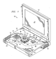
- FIGURE 1 is a diagrammatic fragmentary perspective view of an apparatus which is a portable computer 10, and which embodies aspects of the present invention.
- the computer 10 includes a housing 12 and a lid 13.
- the lid 13 is pivotally supported on the housing 12 for movement between an open position which is shown in FIGURE 1 , and a closed position in which the lid is adjacent the top surface of the housing 12.
- the lid 13 contains a liquid crystal display (LCD) panel 17 of a type commonly used in portable computers.
- LCD liquid crystal display
- a plurality of manually operable keys 18 are provided on top of the housing 12, and collectively define a computer keyboard.
- the keyboard conforms to an industry-standard configuration, but it could alternatively have some other configuration.
- the top wall of the housing 12 has, in a central portion thereof, a cluster of openings 21 which each extend through the top wall. The openings 21 collectively serve as an intake port.
- the housing 12 also has, at an end of the right sidewall which is nearest the lid 13, a cluster of openings 22 that collectively serve as a discharge port.
- the left sidewall of the housing 12 has, near the end remote from the lid 13, a cluster of openings 23 that collectively serve as a further discharge port.
- a circuit board 31 is provided within the housing 12.
- the circuit board 31 has a large number of components thereon, but for clarity these components are not all depicted in FIGURE 1 .
- FIGURE 1 shows only three components 36, 37 and 38, each of which produces heat that must be dissipated.
- the integrated circuit 36 contains a high-performance processor, which in the disclosed embodiment is a known device that can be commercially obtained under the trademark PENTIUM from Intel Corporation of Santa Clara, California.
- the present invention is compatible with a wide variety of integrated circuits, including those containing other types of processors.
- a cooling assembly 41 is mounted on top of the integrated circuit 36, in thermal communication therewith.
- the cooling assembly 41 may be mounted on the integrated circuit 36 using a thermally conductive epoxy, or in any other suitable manner that facilitates a flow of heat between the integrated circuit 36 and the cooling assembly 41.
- the internal structure of the cooling assembly 41 is described in more detail later.
- the cooling assembly 41 has an outwardly projecting tab 42 which is thermally conductive, for a purpose discussed later.
- the cooling assembly 41 draws air into the housing 12 through the intake port defined by the openings 21, as indicated diagrammatically at 43. This air flow passes through the cooling assembly 41, and heat from the cooling assembly 41 is transferred to this air flow. Respective portions of this air flow exit from the cooling assembly 41 in a variety of different horizontal directions, and then travel to and through the discharge port defined by the openings 22 or the discharge port defined by the openings 23. The air flow travels from the cooling assembly 41 to the discharge ports along a number of different flow paths. Some examples of these various flow paths are indicated diagrammatically in FIGURE 1 by broken lines 45-49. As air flows from the cooling assembly 41 to the openings 22 and 23 that define the two discharge ports, the air travels over and picks up heat from components other than the processor, including the components 37 and 38, as well as other components that are not specifically shown in FIGURE 1 .
- the pattern of air flow from the cooling assembly 41 to the discharge ports depends on the number of discharge ports, and on where the discharge ports are located. Further, when there are two or more discharge ports, the relative sizes of the discharge ports will affect the pattern of air flow, where the size of each port is the collective size of all of the openings defining that port. For example, if the collective size of the openings in one of the discharge ports exceeds the collective size of the openings in the other discharge port, more air will flow to and through the former than the latter.
- hot spots can be identified in the circuitry provided on the circuit board 31, and then the location and effective size of each discharge port can be selected so as to obtain an air flow pattern in which the amount of air flowing past each identified hot spot is more than would otherwise be the case.
- the integrated circuit 37 has a thermally conductive metal plate 56 mounted to the top surface thereof, in a manner so that the plate 56 and the integrated circuit 37 are in thermal communication.
- the plate 56 is secured to the integrated circuit 37 using a thermally conductive epoxy, but this could alternatively be effected in some other suitable manner.
- a heat pipe 58 of a known type has one end soldered to the plate 56, and its other end soldered to the tab 42 of the cooling apparatus 41.
- the heat pipe 58 could be thermally coupled to the plate 56 and the tab 42 in some other suitable manner, for example through use of a thermally conductive epoxy, or by providing metal parts on the plate 56 and the tab 42 which can be crimped around the ends of the heat pipe 58.
- the cooling apparatus 41 could be mounted on the circuit board 31 at a location near the processor integrated circuit 36, a plate such as that shown at 56 could be provided on the processor integrated circuit 36, and the heat pipe 58 could extend from the plate on the processor integrated circuit to the cooling apparatus 41.
- the integrated circuit 38 has a heat sink 61 mounted on the top surface thereof, in a manner so that the heat sink 61 and the integrated circuit 38 are in thermal communication.
- the heat sink 61 is secured to the integrated circuit 38 using a thermally conductive epoxy, but it could alternatively be secured in place in any other suitable manner.
- the heat sink 61 is made of a metal such as aluminum, or a metal alloy that is primarily aluminum, and has a base with an array of vertically upwardly extending projections. As air travels from the cooling assembly 41 along the path 45 to the discharge port defined by the openings 23, it flows over the heat sink 61 and through the projections thereof.
- Heat generated by the integrated circuit 38 passes to the heat sink 61, and then from the heat sink 61 to the air flowing along path 45.
- the heat sink 61 transfers heat from the integrated circuit 38 to the air flow 45 at a lower temperature than would be the case if the heat sink 61 was omitted and heat had to be transferred directly from the integrated circuit 38 to the air flow.
- a wall or vane 63 is provided within the housing 12, and extends vertically between the circuit board 31 and the underside of the top wall of the housing 12.
- the vane 63 is an integral part of the housing top wall, and projects downwardly from the top wall.
- the vane 63 could alternatively be a physically separate part, and could be mounted on the top wall, or on the circuit board 31.
- the vane 63 influences the pattern of air which flows from the cooling assembly 41 to the discharge port defined by the openings 23. After one or more hot spots on a given circuit board have been identified, one or more vanes of the type shown at 63 can be added, with each such vane having a size, orientation and location that help to increase the amount of air flowing past at least one of the hot spots.
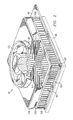
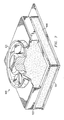
- FIGURE 2 is a diagrammatic fragmentary perspective view which shows the cooling assembly 41 in an enlarged scale, and which also shows in broken lines the integrated circuit 36 on which the cooling assembly 41 is mounted.
- the cooling assembly 41 includes a bottom plate 101 which is made of aluminum or an aluminum alloy, and which has approximately a square shape, except for an integral projection that extends outwardly on one side thereof to serve as the tab 42.
- a top plate 103 is made of aluminum or an aluminum alloy, and has a square shape which conforms in size to the bottom plate 101.
- the top plate 103 is supported a small distance above the bottom plate 101 by four vertical posts disposed at the respective corners of the plates 101 and 103, three of these posts being visible at 106-108 in FIGURE 2 .
- the posts are secured to the plates 101 and 103 by welding or brazing, or in any other suitable manner.
- the top plate 103 has a square opening 111 extending vertically through it.
- the opening 111 is only slightly smaller in size than the plate 103 itself, such that the top plate 103 is effectively a square frame.
- a plenum 116 of small vertical height is made of aluminum or an aluminum alloy, and in a top view has a square shape which conforms in size to the square top plate 103.
- the plenum could be made of some other suitable material, such as a polycarbonate material.
- the plenum 116 is fixedly secured to the top plate 103, for example by welding or brazing, by a thermally conductive epoxy, by a thermally conductive double sided tape of a known type, or in any other suitable manner.
- the bottom wall of the plenum 116 has a square opening 117, which is aligned with and has the same size as the opening 111 provided through the top plate 103.
- the top wall of the plenum 116 has a circular opening 118.
- a low-profile electric fan 121 has a relatively small vertical height, has a diameter somewhat greater than the diameter of the opening 118, and is fixedly secured to the top wall of the plenum 116 so as to be coaxially aligned with the circular opening 118.
- the fan causes air to flow downwardly through the plenum 116.
- the cooling assembly 41 includes, between the top and bottom plates 103 and 101, a thermally conductive finstock 141.
- the finstock 141 is fixedly mounted on the top surface of the bottom plate 101, so as to be in thermal communication therewith.
- the finstock 141 is secured to the bottom plate 101 by a thermally conductive epoxy of a known type, but it could alternatively be secured to the bottom plate 101 in any other suitable manner, for example by welding or brazing.
- the finstock 141 is described in more detail with reference to FIGUREs 3 and 4 .
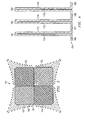
- FIGURE 3 is a diagrammatic top view of the finstock 141
- FIGURE 4 is a diagrammatic fragmentary sectional side view of a portion of the finstock 141.
- the finstock 141 includes four separate parts 151-154, each of which is approximately square when viewed from the top, except that one outer corner of each has a small recess which provides clearance for a respective one of the four support posts, three of these posts being visible at 106-108 in FIGURE 2 .
- the opposite or inner corners of the parts 151-154 are all located at a common point disposed along a vertical axis 158, which extends perpendicular to the plane of FIGURE 3 .
- the fan 121 ( FIGURE 2 ) and the opening 118 in the plenum top wall are both concentric to the axis 158 ( FIGURE 3 ).
- the parts 151-154 of the finstock 141 are all identical to each other, and therefore only the part 151 is described here in detail.
- the part 151 includes an approximately horizontal base portion 161, and a plurality of parallel fins that each project vertically upwardly from the base portion 161.
- the part 151 is made from a thin sheet of an aluminum alloy, which in the disclosed embodiment is an alloy commonly known in the art as Aluminum 3003, and which typically includes 1.2% magnesium with the remainder made of aluminum, although the definition for this alloy allows for magnesium of 1% to 1.5%, silicon less than 0.6%, iron less than 0.7%, copper less than 0.2%, zinc less than 0.1%, and other elements less than 0.05%, where all element other than aluminum and magnesium total less than 0.15%.
- the aluminum alloy sheet which serves as the part 151 is bent to have the cross-sectional shape shown in FIGURE 4 .
- the part 151 could alternatively be made of some other suitable material that conducts heat well.
- the bent aluminum sheet has a plurality of vertically extending portions that each serve as a sidewall, six of which are visible at 171-176. These sidewalls are arranged in pairs, where the sidewalls of each pair are closely adjacent one another, and are spaced from the sidewalls of other pairs.
- the bent aluminum sheet also includes a plurality of top wall portions that each extend between the upper ends of the sidewalls of a respective pair, three of the top wall portions being visible at 181-183.
- the aluminum sheet further includes a plurality of bottom wall portions that each extend between the lower ends of two sidewalls which are in different pairs, four of the bottom wall portions being visible at 186-189.
- the bottom wall portions including those shown at 186-189, collectively define the base 161 ( FIGURE 3 ) of the part 151.
- the sidewall pair 171-172 and the top wall portion 181 define a fin 162 ( FIGURE 3 ), the sidewall pair 173-174 and the top wall portion 182 define another fin 162, and the sidewall pair 175-176 and the top wall portion 183 define yet another fin 162.
- the sidewalls of each pair are disposed sufficiently closely to each other so that there is not enough room between them for any significant flow of air, and thus it is not necessary to form openings in the top wall portions in order to allow part of the air flow to enter the region between the sidewalls of each pair.
- the parts 151-154 can be fabricated by bending a large aluminum sheet so that it has the profile shown in FIGURE 4 , and then cutting the parts 151-154 from this large sheet with an abrasive water jet.
- the parts 151-154 each have one fin which is located approximately in the center thereof, and which extends diagonally across that part in a direction substantially radially of the axis 158.
- Each of the other fins on each part 151-154 has an inner end which engages the inner end of a respective fin on an adjacent part 151-154.
- the fins 162 of the finstock 141 have a thickness of approximately 0.01524 centimeters (0.006 inch), a vertical height of 0.635 centimeters (0.25 inch), and a pitch of 18 fins per 2.54 centimeters (inch).
- heat produced by the circuitry within the integrated circuit 36 propagates upwardly from the integrated circuit 36 to the bottom plate 101 of the cooling apparatus 41, and then from the bottom plate 101 into the parts 151-154 of the finstock 141.
- the fan 121 draws air into the housing 12 through the openings 22 that define the intake port, and forces this air to flow downwardly through the plenum 116 and the opening 111 in the top plate 103.
- the fins of the four finstock parts 151-154 cause this air flow to split into portions that are redirected to flow in four different horizontal directions between adjacent fins, as indicated diagrammatically by the arrows provided around the finstock 141 in FIGURE 3 .
- the relative lengths of the arrows in FIGURE 3 is a diagrammatic indication of the volume and velocity of air exiting the finstock 141 at each of a number of locations along the periphery thereof.
- the low pressure drop permits the fan 121 to drive the desired air flow with minimal effort, thereby minimizing the amount of battery power consumed by the fan, which is always advantageous in a portable computer. Further, the low pressure drop minimizes the audible noise of the air flow, and facilitates better cooling.
- the cooling assembly 41 can dissipate 20 watts of heat in a 5.08 centimeter x 5.08 centimeter (2 inch x 2 inch) footprint, with a temperature rise of about 15°C.
- the overall thickness of the cooling assembly is less than about 1.016 centimeter (0.4 inch).
- the power consumption of the fan is only about 2 to 3 watts, of which about 0.7 watt relates to cooling of the component 36 containing the processor, and the remainder relates to the additional pressure drop involved in controlling the air flow from the cooling assembly 41 to the openings 22 and 23 that define the discharge ports.
- the volume of air flow through the cooling assembly 41 is about 9.9958 cubic centimeters (3.53 cubic feet) per minute, and the pressure loss is 0.07366 centimeters (0.029 inches) of water.
- FIGURE 5 is a diagrammatic top view similar to FIGURE 3 , but showing a finstock 241 which is an alternative embodiment of the finstock 141 of FIGURE 3 .
- the finstock 241 is generally similar to the finstock 141, except for differences which are discussed below.
- the finstock 241 includes four parts 251-254, which are generally similar to the parts 151-154. The primary difference is that, in a top view, the parts 251-254 each have a shape which is approximately a right triangle, rather than a square. The 90° apexes of these triangular parts are all located at a common point which is disposed along the vertical axis 158. The other two corners of each part have a small rounded recess that provides clearance for a respective one of the four corner posts.
- the finstock 241 splits and redirects the vertical air flow in portions that flow in four horizontal directions, in a manner similar to the finstock 141. Further, the finstock 241 has a low pressure drop, which is comparable to the low pressure drop of the finstock 141.
- the finstock 141 is fabricated as four separate parts 151-154, each of which is a bent sheet of aluminum.
- the four parts 251-254 of the finstock 241 of FIGURE 5 are each a bent sheet of aluminum.
- a finstock which is made of some other material that conducts heat well.
- a single integral finstock could be made by injection molding techniques.
- FIGURE 6 is a diagrammatic fragmentary sectional side view of such an injection-molded finstock, which is identified by reference numeral 341.
- the finstock 341 is injection-molded from a thermally conductive molding material, such as a material having a base polymer which is a thermally conductive liquid crystalline polymer (LCP) or a thermally conductive polyphenylene sulfide (PPS).
- a thermally conductive molding material such as a material having a base polymer which is a thermally conductive liquid crystalline polymer (LCP) or a thermally conductive polyphenylene sulfide (PPS).
- suitable base polymers are available commercially under the trademark COOLPOLY from Cool Polymers, Inc. of Warwick, Rhode Island, including LCP product COOLPOLY E2, and PPS products COOLPOLY RB020 AND COOLPOLY RS012.
- the finstock 341 is a single injection molded part, rather than several separate sections as in the embodiments of FIGUREs 1-5 . It will be recognized that, as an alternative to injection molding, the finstock 341 could be formed by resin transfer molding.
- the top plate 103 can optionally be omitted, and the plenum 116 can be directly secured to the tops of the fins of finstock 341, for example using a suitable known epoxy adhesive. In that case, it is possible to optionally omit the four support posts (three of which are visible at 106-108).
- a molded finstock could be similar to that shown at 341 in FIGURE 6 , except that the top plate 103 could be fabricated as an integral part of the molded finstock 341, and the plenum 116 could be directly secured to the integral top plate.
- FIGURE 7 is a diagrammatic fragmentary perspective view similar to FIGURE 2 , but showing a cooling assembly 441 which is an alternative arrangement of the cooling assembly 41 of FIGURE 2 .
- the cooling assembly 441 is identical to the cooling assembly 41, except for the difference which is discussed below. More specifically, the finstock 141 of the assembly 41 has been omitted in the assembly 441, and an approximately rectangular block 444 of porous material is provided in its place.
- the block 444 extends vertically from the bottom plate 101 to the top plate 103, and is physically and thermally secured to the bottom plate 101 by welding, brazing or a thermally conductive epoxy, or in some other suitable manner.
- the porous block 444 is made from a porous open-cell sintered material which is heat conductive, but it could alternatively be made from a porous open-cell foamed material which is heat conductive.
- the sintered or foamed porous material used for the block 444 is aluminum, but it could alternatively be some other suitable heat-conductive material.
- the porous block 444 is relatively inexpensive. The downward air flow from the fan 121 enters the central portion of the porous block 444, and then flows horizontally outwardly through the block 444 in a variety of different radial directions.
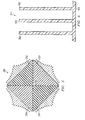
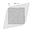
- FIGURE 8 is a diagrammatic top view of a finstock 541 which is a die-cast part made of a zinc alloy, which is an alternative arrangement of the finstock 141 of FIGUREs 2 and 3 , and which can be substituted for the finstock 141 in the cooling assembly 41 of FIGURE 2 .
- the finstock 541 has horizontal dimensions of about 5.08 cm x 5.08 cm (2 inches by 2 inches), with the base plate about 0.127 cm (0.05 inch) thick and the fins about 0.635 cm (0.25 inch) high. There are about 16 fins per inch, and the fins have rounded tips.
- the fins increase in thickness from the tip to the base, with a thickness of about 0.0254 cm (0.01 inch) near the tip and about 0.0635 cm (0.025 inch) near the base. Between each adjacent pair of fins, the top surface of the base is slightly rounded, so as to be concave.
- the zinc alloy used for the finstock 541 is an alloy commonly known as zinc die-casting Alloy 3, which includes 3.5% to 4.3% aluminum, a maximum of 0.25% copper, 0.02% to 0.05% magnesium, a maximum of 0.1% iron, a maximum of 0.005% lead, a maximum of 0.004% cadmium, and a maximum of 0.003% tin, with the balance being zinc.
- these specific dimensions and specific alloy given above for the finstock 541 are exemplary, and it will be recognized that variations of the dimensions and the material are possible.
- the present invention provides a number of technical advantages.
- One such technical advantage results from the provision within a portable computer of a low-profile cooling assembly for a circuit component such as the processor.
- the cooling assembly effects a forced flow of air drawn from externally of the housing, and the air flow from this cooling assembly is routed within the housing to facilitate cooling of other heat-dissipating components.
- the routing of this air flow is facilitated by techniques which include selection of the number of discharge ports through which the air flow exits the housing, and selection of the location and/or effective size of each such discharge port.
- the routing of the air flow can also be facilitated by the use of strategically placed vanes within the housing.
- a related advantage is realized where a component has a local finned heat sink in order to facilitate the efficient transfer of heat from that component to the air flow which is traveling from the cooling assembly to a discharge port. Still another advantage is realized where a heat pipe is provided within the housing to help transfer heat, for example from a heat dissipating component to the cooling assembly.
- the cooling assembly uses a forced air flow which is split to flow through a thermally conductive section in several significantly different directions.
- a different thermally conductive section is a finstock which splits the airflow into portions flowing in multiple directions. Splitting the air flow yields a low pressure drop, which facilitates low power consumption and minimal audible noise for the cooling assembly. Further, it is effected with a finstock that has a relatively low height but provides a large surface area that offers a high degree of convective heat transfer.
- Another advantage is that the cooling assembly achieves these advantages even though it has a very low profile which, when used in a portable computer, permits the housing of the computer to be relatively thin.
Landscapes
- Engineering & Computer Science (AREA)
- Computer Hardware Design (AREA)
- Physics & Mathematics (AREA)
- General Physics & Mathematics (AREA)
- Power Engineering (AREA)
- Microelectronics & Electronic Packaging (AREA)
- Condensed Matter Physics & Semiconductors (AREA)
- Theoretical Computer Science (AREA)
- Human Computer Interaction (AREA)
- General Engineering & Computer Science (AREA)
- Chemical & Material Sciences (AREA)
- Materials Engineering (AREA)
- Cooling Or The Like Of Electrical Apparatus (AREA)
- Cooling Or The Like Of Semiconductors Or Solid State Devices (AREA)
Description
- This invention relates in general to techniques for cooling circuit devices and, more particularly, to techniques for cooling circuit devices disposed within a portable computer.
- Over the past fifteen years, personal computers have enjoyed a progressively increasing popularity, including portable computers of the type commonly known as "laptop" and "notebook" computers. During this same time period, significant advances have been made in the design of the processors used in personal computers, including portable computers. In this regard, the amount of circuitry which can be fabricated in a given area of an integrated circuit has increased significantly, thereby facilitating the implementation and fabrication of significantly more sophisticated processor designs. Further, the operational capabilities of processors have increased dramatically, and there have also been significant increases in the speed at which processors can operate.
- A side effect of these technological advances is that state-of-the-art processors and other integrated circuits used in personal computers produce significantly more heat during normal operation than their predecessors did only a few years ago. In some systems, the processors and related components are operated at clock speeds significantly below their maximum rated clock speeds, in order to reduce the amount of heat generated, and thus avoid the need to provide active cooling. However, operating the processor at a speed less than its maximum rated speed decreases the capability of the system, and thus the value of the system in the eyes of consumers, which is undesirable. Therefore, and focusing specifically on processor chips, technology has reached a point where, in order to operate a processor at its maximum rated speed while effectively dissipating the heat which is generated, it is relatively standard for a desktop computer to have a forced-air cooling arrangement for the high-performance processor used in it. In particular, it is common to dedicate a relatively large heat sink and/or a powerful fan to the specific task of cooling the processor of a desktop computer. However, while these cooling arrangements have been generally satisfactory for use in desktop computers, they are not entirely satisfactory for use in portable computers.
- More specifically, due in part to marketing efforts and consumer preferences, portable computers have evolved in design to a point where they are relatively thin and lightweight. In order to accommodate in a portable computer the type of cooling arrangement that has now become common in desktop computers, there would have to be an increase in both the thickness and weight of the portable computer. But an increase in the weight and/or thickness of a portable computer is undesirable from a commercial perspective, because it runs contrary to consumer preference for thin and lightweight units. Another significant marketing criteria for portable computers is the length of time that a fully-charged battery can run a portable computer before the battery becomes discharged. The powerful fans used in many desktop cooling arrangements would tend to consume a significant amount of battery power if used in a portable computer, and would thus undesirably shorten the effective battery life. Although a larger battery could be used, this would result in an increase in the size and/or weight of the portable computer, which as discussed above is undesirable.
- The above-mentioned cooling arrangements for processors provide little or no benefit in regard to cooling of other circuit components that are separate from but associated with the processors. To date, it has typically not been necessary to provide components other than the processor with a direct cooling arrangement. However, advances in technology have increased the amount of heat generated by these other types of components, to the point where more effective cooling techniques are needed for these components.
- Some prior attempts have been made to provide effective cooling in portable computers, but the results have not been entirely satisfactory. For example, heat pipes have been used to conduct heat from an interior component to an external finned heat sink, but the heat sink adds undesirable weight. Although the additional weight can be reduced to some extent by making the heat sink from a lightweight material such as magnesium, magnesium is relatively expensive, and the added expense is undesirable. Examples of finned heat sinks can be found in
EP 0860874 andUS 4715438 As another example, some portable computers have vents provided in upper and/or lower portions of the housing, in order to facilitate cooling through natural convection currents. However, this approach provides only limited benefit, and technology is reaching a point where this type of natural convection cooling is simply inadequate to remove the amount of heat that is being generated. - From the foregoing, it may be appreciated that a need has arisen for a method and apparatus which facilitate efficient cooling in a portable computer.
- According to the present invention there is provided, as defined more particularly in the appended claims, an apparatus for cooling a portable computer and a method of cooling a portable computer which includes a housing having therein circuitry with a component.
- A better understanding of the present invention will be realized from the detailed description which follows, taken in conjunction with the accompanying drawings, in which:
-
FIGURE 1 is a diagrammatic fragmentary perspective view of a portable computer that embodies aspects of the present invention; -
FIGURE 2 is a diagrammatic fragmentary perspective view of a cooling assembly which is part of the portable computer ofFIGURE 1 ; -
FIGURE 3 is a diagrammatic top view of a finstock embodiment of a thermally conductive section which is part of the cooling assembly ofFIGURE 2 ; -
FIGURE 4 is a diagrammatic fragmentary sectional side view of the finstock ofFIGURE 3 ; -
FIGURE 5 is a diagrammatic top view similar toFIGURE 3 , but showing an alternative embodiment of a finstock of the thermally conductive section; -
FIGURE 6 is a diagrammatic fragmentary sectional side view similar toFIGURE 4 , but showing the alternative embodiment of the finstock ofFIGURE 5 ; -
FIGURE 7 is a diagrammatic fragmentary perspective view similar toFIGURE 2 , but showing an alternative arrangement of a thermally conductive section which is part of the cooling assembly ofFIGURE 2 ; and -
FIGURE 8 is a diagrammatic top view similar toFIGURE 3 , but showing an alternative arrangement of a finstock of the thermally conductive section which is part of the cooling assembly ofFIGURE 2 . -
FIGURE 1 is a diagrammatic fragmentary perspective view of an apparatus which is aportable computer 10, and which embodies aspects of the present invention. Thecomputer 10 includes ahousing 12 and alid 13. Thelid 13 is pivotally supported on thehousing 12 for movement between an open position which is shown inFIGURE 1 , and a closed position in which the lid is adjacent the top surface of thehousing 12. Thelid 13 contains a liquid crystal display (LCD)panel 17 of a type commonly used in portable computers. - A plurality of manually
operable keys 18 are provided on top of thehousing 12, and collectively define a computer keyboard. In the disclosed embodiment, the keyboard conforms to an industry-standard configuration, but it could alternatively have some other configuration. The top wall of thehousing 12 has, in a central portion thereof, a cluster ofopenings 21 which each extend through the top wall. Theopenings 21 collectively serve as an intake port. Thehousing 12 also has, at an end of the right sidewall which is nearest thelid 13, a cluster ofopenings 22 that collectively serve as a discharge port. Further, the left sidewall of thehousing 12 has, near the end remote from thelid 13, a cluster ofopenings 23 that collectively serve as a further discharge port. - A
circuit board 31 is provided within thehousing 12. Thecircuit board 31 has a large number of components thereon, but for clarity these components are not all depicted inFIGURE 1 . In particular,FIGURE 1 shows only threecomponents circuit 36 contains a high-performance processor, which in the disclosed embodiment is a known device that can be commercially obtained under the trademark PENTIUM from Intel Corporation of Santa Clara, California. However, the present invention is compatible with a wide variety of integrated circuits, including those containing other types of processors. - A
cooling assembly 41 is mounted on top of the integratedcircuit 36, in thermal communication therewith. Thecooling assembly 41 may be mounted on the integratedcircuit 36 using a thermally conductive epoxy, or in any other suitable manner that facilitates a flow of heat between the integratedcircuit 36 and thecooling assembly 41. The internal structure of thecooling assembly 41 is described in more detail later. Thecooling assembly 41 has an outwardly projectingtab 42 which is thermally conductive, for a purpose discussed later. - The
cooling assembly 41 draws air into thehousing 12 through the intake port defined by theopenings 21, as indicated diagrammatically at 43. This air flow passes through thecooling assembly 41, and heat from thecooling assembly 41 is transferred to this air flow. Respective portions of this air flow exit from thecooling assembly 41 in a variety of different horizontal directions, and then travel to and through the discharge port defined by theopenings 22 or the discharge port defined by theopenings 23. The air flow travels from thecooling assembly 41 to the discharge ports along a number of different flow paths. Some examples of these various flow paths are indicated diagrammatically inFIGURE 1 by broken lines 45-49. As air flows from the coolingassembly 41 to theopenings components FIGURE 1 . - The pattern of air flow from the cooling
assembly 41 to the discharge ports depends on the number of discharge ports, and on where the discharge ports are located. Further, when there are two or more discharge ports, the relative sizes of the discharge ports will affect the pattern of air flow, where the size of each port is the collective size of all of the openings defining that port. For example, if the collective size of the openings in one of the discharge ports exceeds the collective size of the openings in the other discharge port, more air will flow to and through the former than the latter. With this in mind, hot spots can be identified in the circuitry provided on thecircuit board 31, and then the location and effective size of each discharge port can be selected so as to obtain an air flow pattern in which the amount of air flowing past each identified hot spot is more than would otherwise be the case. - The
integrated circuit 37 has a thermallyconductive metal plate 56 mounted to the top surface thereof, in a manner so that theplate 56 and theintegrated circuit 37 are in thermal communication. In the embodiment ofFIGURE 1 , theplate 56 is secured to theintegrated circuit 37 using a thermally conductive epoxy, but this could alternatively be effected in some other suitable manner. Aheat pipe 58 of a known type has one end soldered to theplate 56, and its other end soldered to thetab 42 of thecooling apparatus 41. Alternatively, theheat pipe 58 could be thermally coupled to theplate 56 and thetab 42 in some other suitable manner, for example through use of a thermally conductive epoxy, or by providing metal parts on theplate 56 and thetab 42 which can be crimped around the ends of theheat pipe 58. As still another alternative, in order to help keep thehousing 12 thin, thecooling apparatus 41 could be mounted on thecircuit board 31 at a location near the processor integratedcircuit 36, a plate such as that shown at 56 could be provided on the processor integratedcircuit 36, and theheat pipe 58 could extend from the plate on the processor integrated circuit to thecooling apparatus 41. - The
integrated circuit 38 has aheat sink 61 mounted on the top surface thereof, in a manner so that theheat sink 61 and theintegrated circuit 38 are in thermal communication. In the embodiment ofFIGURE 1 , theheat sink 61 is secured to theintegrated circuit 38 using a thermally conductive epoxy, but it could alternatively be secured in place in any other suitable manner. Theheat sink 61 is made of a metal such as aluminum, or a metal alloy that is primarily aluminum, and has a base with an array of vertically upwardly extending projections. As air travels from the coolingassembly 41 along thepath 45 to the discharge port defined by theopenings 23, it flows over theheat sink 61 and through the projections thereof. Heat generated by the integratedcircuit 38 passes to theheat sink 61, and then from theheat sink 61 to the air flowing alongpath 45. Theheat sink 61 transfers heat from the integratedcircuit 38 to theair flow 45 at a lower temperature than would be the case if theheat sink 61 was omitted and heat had to be transferred directly from the integratedcircuit 38 to the air flow. - A wall or
vane 63 is provided within thehousing 12, and extends vertically between thecircuit board 31 and the underside of the top wall of thehousing 12. In the disclosed embodiment, thevane 63 is an integral part of the housing top wall, and projects downwardly from the top wall. However, thevane 63 could alternatively be a physically separate part, and could be mounted on the top wall, or on thecircuit board 31. Thevane 63 influences the pattern of air which flows from the coolingassembly 41 to the discharge port defined by theopenings 23. After one or more hot spots on a given circuit board have been identified, one or more vanes of the type shown at 63 can be added, with each such vane having a size, orientation and location that help to increase the amount of air flowing past at least one of the hot spots. -
FIGURE 2 is a diagrammatic fragmentary perspective view which shows the coolingassembly 41 in an enlarged scale, and which also shows in broken lines theintegrated circuit 36 on which the coolingassembly 41 is mounted. The coolingassembly 41 includes abottom plate 101 which is made of aluminum or an aluminum alloy, and which has approximately a square shape, except for an integral projection that extends outwardly on one side thereof to serve as thetab 42. Atop plate 103 is made of aluminum or an aluminum alloy, and has a square shape which conforms in size to thebottom plate 101. Thetop plate 103 is supported a small distance above thebottom plate 101 by four vertical posts disposed at the respective corners of theplates FIGURE 2 . The posts are secured to theplates top plate 103 has asquare opening 111 extending vertically through it. Theopening 111 is only slightly smaller in size than theplate 103 itself, such that thetop plate 103 is effectively a square frame. - A
plenum 116 of small vertical height is made of aluminum or an aluminum alloy, and in a top view has a square shape which conforms in size to the squaretop plate 103. Alternatively, the plenum could be made of some other suitable material, such as a polycarbonate material. Theplenum 116 is fixedly secured to thetop plate 103, for example by welding or brazing, by a thermally conductive epoxy, by a thermally conductive double sided tape of a known type, or in any other suitable manner. The bottom wall of theplenum 116 has asquare opening 117, which is aligned with and has the same size as theopening 111 provided through thetop plate 103. - The top wall of the
plenum 116 has acircular opening 118. A low-profileelectric fan 121 has a relatively small vertical height, has a diameter somewhat greater than the diameter of theopening 118, and is fixedly secured to the top wall of theplenum 116 so as to be coaxially aligned with thecircular opening 118. When electric current is supplied to thefan 121 through not-illustrated wires, the fan causes air to flow downwardly through theplenum 116. - The cooling
assembly 41 includes, between the top andbottom plates conductive finstock 141. Thefinstock 141 is fixedly mounted on the top surface of thebottom plate 101, so as to be in thermal communication therewith. In the disclosed embodiment, thefinstock 141 is secured to thebottom plate 101 by a thermally conductive epoxy of a known type, but it could alternatively be secured to thebottom plate 101 in any other suitable manner, for example by welding or brazing. Thefinstock 141 is described in more detail with reference toFIGUREs 3 and 4 . - In this regard,
FIGURE 3 is a diagrammatic top view of thefinstock 141, andFIGURE 4 is a diagrammatic fragmentary sectional side view of a portion of thefinstock 141. With reference toFIGURE 3 , thefinstock 141 includes four separate parts 151-154, each of which is approximately square when viewed from the top, except that one outer corner of each has a small recess which provides clearance for a respective one of the four support posts, three of these posts being visible at 106-108 inFIGURE 2 . The opposite or inner corners of the parts 151-154 are all located at a common point disposed along avertical axis 158, which extends perpendicular to the plane ofFIGURE 3 . The fan 121 (FIGURE 2 ) and theopening 118 in the plenum top wall are both concentric to the axis 158 (FIGURE 3 ). - The parts 151-154 of the
finstock 141 are all identical to each other, and therefore only thepart 151 is described here in detail. With reference toFIGURE 3 , thepart 151 includes an approximatelyhorizontal base portion 161, and a plurality of parallel fins that each project vertically upwardly from thebase portion 161. Thepart 151 is made from a thin sheet of an aluminum alloy, which in the disclosed embodiment is an alloy commonly known in the art as Aluminum 3003, and which typically includes 1.2% magnesium with the remainder made of aluminum, although the definition for this alloy allows for magnesium of 1% to 1.5%, silicon less than 0.6%, iron less than 0.7%, copper less than 0.2%, zinc less than 0.1%, and other elements less than 0.05%, where all element other than aluminum and magnesium total less than 0.15%. - The aluminum alloy sheet which serves as the
part 151 is bent to have the cross-sectional shape shown inFIGURE 4 . However, thepart 151 could alternatively be made of some other suitable material that conducts heat well. In this regard, the bent aluminum sheet has a plurality of vertically extending portions that each serve as a sidewall, six of which are visible at 171-176. These sidewalls are arranged in pairs, where the sidewalls of each pair are closely adjacent one another, and are spaced from the sidewalls of other pairs. The bent aluminum sheet also includes a plurality of top wall portions that each extend between the upper ends of the sidewalls of a respective pair, three of the top wall portions being visible at 181-183. The aluminum sheet further includes a plurality of bottom wall portions that each extend between the lower ends of two sidewalls which are in different pairs, four of the bottom wall portions being visible at 186-189. - The bottom wall portions, including those shown at 186-189, collectively define the base 161 (
FIGURE 3 ) of thepart 151. The sidewall pair 171-172 and thetop wall portion 181 define a fin 162 (FIGURE 3 ), the sidewall pair 173-174 and thetop wall portion 182 define anotherfin 162, and the sidewall pair 175-176 and thetop wall portion 183 define yet anotherfin 162. The sidewalls of each pair are disposed sufficiently closely to each other so that there is not enough room between them for any significant flow of air, and thus it is not necessary to form openings in the top wall portions in order to allow part of the air flow to enter the region between the sidewalls of each pair. The parts 151-154 can be fabricated by bending a large aluminum sheet so that it has the profile shown inFIGURE 4 , and then cutting the parts 151-154 from this large sheet with an abrasive water jet. - Referring again to
FIGURE 3 , it will be noted that the parts 151-154 each have one fin which is located approximately in the center thereof, and which extends diagonally across that part in a direction substantially radially of theaxis 158. Each of the other fins on each part 151-154 has an inner end which engages the inner end of a respective fin on an adjacent part 151-154. In the disclosed embodiment, thefins 162 of thefinstock 141 have a thickness of approximately 0.01524 centimeters (0.006 inch), a vertical height of 0.635 centimeters (0.25 inch), and a pitch of 18 fins per 2.54 centimeters (inch). - In operation, and with reference to
FIGURE 2 , heat produced by the circuitry within the integratedcircuit 36 propagates upwardly from the integratedcircuit 36 to thebottom plate 101 of thecooling apparatus 41, and then from thebottom plate 101 into the parts 151-154 of thefinstock 141. Thefan 121 draws air into thehousing 12 through theopenings 22 that define the intake port, and forces this air to flow downwardly through theplenum 116 and theopening 111 in thetop plate 103. - When this downward flow of air reaches the
finstock 141, the fins of the four finstock parts 151-154 cause this air flow to split into portions that are redirected to flow in four different horizontal directions between adjacent fins, as indicated diagrammatically by the arrows provided around thefinstock 141 inFIGURE 3 . The relative lengths of the arrows inFIGURE 3 is a diagrammatic indication of the volume and velocity of air exiting thefinstock 141 at each of a number of locations along the periphery thereof. By splitting the air flow into portions which are each redirected to flow in one of four different directions, thefinstock 141 gives the cooling apparatus 41 a very low pressure drop, which facilitates a higher rate of air flow. The low pressure drop permits thefan 121 to drive the desired air flow with minimal effort, thereby minimizing the amount of battery power consumed by the fan, which is always advantageous in a portable computer. Further, the low pressure drop minimizes the audible noise of the air flow, and facilitates better cooling. - In this disclosed embodiment, the cooling
assembly 41 can dissipate 20 watts of heat in a 5.08 centimeter x 5.08 centimeter (2 inch x 2 inch) footprint, with a temperature rise of about 15°C. The overall thickness of the cooling assembly is less than about 1.016 centimeter (0.4 inch). The power consumption of the fan is only about 2 to 3 watts, of which about 0.7 watt relates to cooling of thecomponent 36 containing the processor, and the remainder relates to the additional pressure drop involved in controlling the air flow from the coolingassembly 41 to theopenings assembly 41 is about 9.9958 cubic centimeters (3.53 cubic feet) per minute, and the pressure loss is 0.07366 centimeters (0.029 inches) of water. -
FIGURE 5 is a diagrammatic top view similar toFIGURE 3 , but showing afinstock 241 which is an alternative embodiment of thefinstock 141 ofFIGURE 3 . Thefinstock 241 is generally similar to thefinstock 141, except for differences which are discussed below. In particular, thefinstock 241 includes four parts 251-254, which are generally similar to the parts 151-154. The primary difference is that, in a top view, the parts 251-254 each have a shape which is approximately a right triangle, rather than a square. The 90° apexes of these triangular parts are all located at a common point which is disposed along thevertical axis 158. The other two corners of each part have a small rounded recess that provides clearance for a respective one of the four corner posts. - In operation, the
finstock 241 splits and redirects the vertical air flow in portions that flow in four horizontal directions, in a manner similar to thefinstock 141. Further, thefinstock 241 has a low pressure drop, which is comparable to the low pressure drop of thefinstock 141. - As described above with reference to
FIGUREs 3 and 4 , thefinstock 141 is fabricated as four separate parts 151-154, each of which is a bent sheet of aluminum. Similarly, the four parts 251-254 of thefinstock 241 ofFIGURE 5 are each a bent sheet of aluminum. It would alternatively be possible, in place of thefinstock 141 andfinstock 241, to use a finstock which is made of some other material that conducts heat well. As one example, a single integral finstock could be made by injection molding techniques. In this regard,FIGURE 6 is a diagrammatic fragmentary sectional side view of such an injection-molded finstock, which is identified byreference numeral 341. - The
finstock 341 is injection-molded from a thermally conductive molding material, such as a material having a base polymer which is a thermally conductive liquid crystalline polymer (LCP) or a thermally conductive polyphenylene sulfide (PPS). For example, suitable base polymers are available commercially under the trademark COOLPOLY from Cool Polymers, Inc. of Warwick, Rhode Island, including LCP product COOLPOLY E2, and PPS products COOLPOLY RB020 AND COOLPOLY RS012. Thefinstock 341 is a single injection molded part, rather than several separate sections as in the embodiments ofFIGUREs 1-5 . It will be recognized that, as an alternative to injection molding, thefinstock 341 could be formed by resin transfer molding. - As a further not-illustrated alternative, if the finstock is molded (for example as shown at 341), then the
top plate 103 can optionally be omitted, and theplenum 116 can be directly secured to the tops of the fins offinstock 341, for example using a suitable known epoxy adhesive. In that case, it is possible to optionally omit the four support posts (three of which are visible at 106-108). As still another alternative, a molded finstock could be similar to that shown at 341 inFIGURE 6 , except that thetop plate 103 could be fabricated as an integral part of the moldedfinstock 341, and theplenum 116 could be directly secured to the integral top plate. -
FIGURE 7 is a diagrammatic fragmentary perspective view similar toFIGURE 2 , but showing acooling assembly 441 which is an alternative arrangement of the coolingassembly 41 ofFIGURE 2 . The coolingassembly 441 is identical to the coolingassembly 41, except for the difference which is discussed below. More specifically, thefinstock 141 of theassembly 41 has been omitted in theassembly 441, and an approximatelyrectangular block 444 of porous material is provided in its place. Theblock 444 extends vertically from thebottom plate 101 to thetop plate 103, and is physically and thermally secured to thebottom plate 101 by welding, brazing or a thermally conductive epoxy, or in some other suitable manner. - The
porous block 444 is made from a porous open-cell sintered material which is heat conductive, but it could alternatively be made from a porous open-cell foamed material which is heat conductive. In this arrangement, the sintered or foamed porous material used for theblock 444 is aluminum, but it could alternatively be some other suitable heat-conductive material. Theporous block 444 is relatively inexpensive. The downward air flow from thefan 121 enters the central portion of theporous block 444, and then flows horizontally outwardly through theblock 444 in a variety of different radial directions. - As discussed above, the
finstock 341 ofFIGURE 6 is an injection molded part of a synthetic material. As another alternative, the finstock could be made from some other heat-conductive material that is amenable to casting or molding, such as a die-cast zinc alloy. In this regard,FIGURE 8 is a diagrammatic top view of afinstock 541 which is a die-cast part made of a zinc alloy, which is an alternative arrangement of thefinstock 141 ofFIGUREs 2 and3 , and which can be substituted for thefinstock 141 in the coolingassembly 41 ofFIGURE 2 . Thefinstock 541 has horizontal dimensions of about 5.08 cm x 5.08 cm (2 inches by 2 inches), with the base plate about 0.127 cm (0.05 inch) thick and the fins about 0.635 cm (0.25 inch) high. There are about 16 fins per inch, and the fins have rounded tips. - The fins increase in thickness from the tip to the base, with a thickness of about 0.0254 cm (0.01 inch) near the tip and about 0.0635 cm (0.025 inch) near the base. Between each adjacent pair of fins, the top surface of the base is slightly rounded, so as to be concave. The zinc alloy used for the
finstock 541 is an alloy commonly known as zinc die-casting Alloy 3, which includes 3.5% to 4.3% aluminum, a maximum of 0.25% copper, 0.02% to 0.05% magnesium, a maximum of 0.1% iron, a maximum of 0.005% lead, a maximum of 0.004% cadmium, and a maximum of 0.003% tin, with the balance being zinc. Of course, these specific dimensions and specific alloy given above for thefinstock 541 are exemplary, and it will be recognized that variations of the dimensions and the material are possible. - The present invention provides a number of technical advantages. One such technical advantage results from the provision within a portable computer of a low-profile cooling assembly for a circuit component such as the processor. In one advantageous configuration, the cooling assembly effects a forced flow of air drawn from externally of the housing, and the air flow from this cooling assembly is routed within the housing to facilitate cooling of other heat-dissipating components. The routing of this air flow is facilitated by techniques which include selection of the number of discharge ports through which the air flow exits the housing, and selection of the location and/or effective size of each such discharge port. The routing of the air flow can also be facilitated by the use of strategically placed vanes within the housing.
- A related advantage is realized where a component has a local finned heat sink in order to facilitate the efficient transfer of heat from that component to the air flow which is traveling from the cooling assembly to a discharge port. Still another advantage is realized where a heat pipe is provided within the housing to help transfer heat, for example from a heat dissipating component to the cooling assembly. Through use of such techniques, a portable computer can be relatively thin and lightweight, and can have a processor which operates at its highest rated speed, while enjoying efficient cooling through use of a configuration that consumes minimal power.
- In an advantageous configuration, the cooling assembly uses a forced air flow which is split to flow through a thermally conductive section in several significantly different directions. A different thermally conductive section is a finstock which splits the airflow into portions flowing in multiple directions. Splitting the air flow yields a low pressure drop, which facilitates low power consumption and minimal audible noise for the cooling assembly. Further, it is effected with a finstock that has a relatively low height but provides a large surface area that offers a high degree of convective heat transfer. Another advantage is that the cooling assembly achieves these advantages even though it has a very low profile which, when used in a portable computer, permits the housing of the computer to be relatively thin.
Claims (33)
- An apparatus for cooling a portable computer (10) which includes:-a housing (12);
circuitry disposed within said housing and having a component (36); and
a temperature adjusting arrangement (41) thermally coupled to said component (36), said temperature adjusting arrangement (41) including:a thermally conductive section (141, 241) which is thermally coupled to said component (36) and having a central axis (158) therethrough; anda fluid supply section (121) disposed on a side of said thermally conductive section (141, 241) opposite from said component (36) and operable to direct a fluid flow along said axis (158) toward said thermally conductive section (141, 241), said thermally conductive section (141, 241) causing said fluid flow to split into a plurality of flow portions which each flow through said thermally conductive section (141, 241) in a direction approximately parallel to a plane perpendicular to said axis (158), said flow portions exiting said thermally conductive section (141, 241) at a plurality of respective locations which are disposed along a substantial portion of the periphery of said thermally conductive section (141, 241);wherein said thermally conductive section (141, 241) includes:-
a base portion (161, 251) with first and second sides facing in respective first and second directions which are opposite and which are each parallel to said axis (158), said first side being said side thermally coupled to said component (36); and
a plurality of fins (162, 252) which project outwardly from said second side of said base portion (161, 251) in said second direction,
characterized in that said fins (162, 252) being arranged in at least three groups (151-154, 251-254) which are distributed angularly about said axis (158); the fins (162, 252) in each said group extending parallel to each other, and each said group including at least one said fin which extends radially of said axis (158), said flow portions being equal in number to the number of said groups, and each flowing away from said axis (158) between and parallel to the fins of a respective said group. - An apparatus according to Claim 1, wherein said plural flow portions each flow away from said axis (158) through said thermally conductive section in a respective one of at least three directions that each extend approximately radially of said axis (158).
- An apparatus according to Claim 1, wherein there are four said groups of fins, the fins of two of said groups extending approximately parallel to a first line which is perpendicular to said axis (158), and the fins of the other two of said groups extending approximately parallel to a second line which is perpendicular to each of said axis (158) and said first line.
- An apparatus according to Claim 1, wherein said housing (12) has first and second ports (21, 23) therethrough, said fluid supply section (121) being in fluid communication with said first port (21) and configured to draw a flow of air into said housing (12) through said first port (21) from externally of said housing (12) said fluid flow including said flow of air, and wherein at least part of the air in said flow portions, after leaving said thermally conductive section, travels to and exits said housing (12) through said second port (23).
- An apparatus according to Claim 4,
wherein said second port (23) is spaced from said thermally conductive section; and
wherein said circuitry includes a further component (38) disposed along a path of air flowing from said thermally conductive section to said second port (23). - An apparatus according to Claim 5, including a vane (63) which is provided within said housing (12) and which influences the route of said path for air flowing from said thermally conductive section to said second port (23).
- An apparatus according to Claim 5, including a heatsink (61) mounted on said further component (38) and disposed in said path for air flowing from said thermally conductive section to said second port (23).
- An apparatus according to Claim 4, wherein said housing (12) has therethrough a third port (22) which is spaced from said second port (23) and configured to provide a passage wherein part of the air in said flow portions, after leaving said thermally conductive section, travels to and exits said housing (12) through said third port (22).
- An apparatus according to Claim 8, wherein said second and third ports (22, 23) have different sizes in order to influence the proportional amount of said air in said air flow sections which flow through each of said second and third ports (22, 23).
- An apparatus according to Claim 4,
wherein said housing (12) has a third port (22) therethrough; wherein said second and third ports (22, 23) are each spaced from said thermally conductive section and from each other;
wherein respective parts of the air in said flow portions, after leaving said thermally conductive section, respectively travel to and exit said housing (12) through said second and third ports (22, 23); and
wherein said circuitry includes two further components (37, 38) which are respectively disposed along respective paths of said respective parts of the air in said flow portions. - An apparatus according to Claim 1,
wherein said circuitry includes first, second, and third components (36-38), said fluid supply section (121) disposed on a side of said thermally conductive section opposite from said first component (36); and
including a heat pipe (58) disposed within said housing (12), said heat pipe (58) having a first portion which is thermally coupled to said second component (37), and having a second portion which is spaced from said first portion and which is thermally coupled to said thermally conductive section;
including a vane (63) provided within said housing (12) and directing at least one flow portion exiting said thermally conductive section to said third component (38). - An apparatus according to Claim 1, wherein said fluid supply section (121) includes a fan that effects an air flow which is said fluid flow.
- An apparatus according to Claim 1, further comprising:a plenum (116) having a lower opening (117) and an upper opening (118), the lower opening (117) being aligned with and having generally the same size and shape as an outer periphery of the thermally conductive section;wherein the plenum (116) is disposed on a side of said thermally conductive section opposite from said component (36) and operable to direct a fluid flow along said axis (158) toward said thermally conductive section.
- An apparatus according to claim 13, wherein the lower opening (117) of the plenum (116) is generally square in shape.
- An apparatus according to claim 13, wherein the thermally conductive section includes a tab (42) that is coupled to a heat pipe (58) and in thermal communication therewith.
- An apparatus (41) according to claim 13, further comprising a top plate (103) having a square opening that extends vertically through it that is sandwiched in between the thermally conductive section (141) and the lower opening (117) of the plenum (116).
- An apparatus according to any preceding claim wherein the plurality of fins are formed from a sheet of aluminum/aluminum alloy.
- An apparatus according to any one of claims 1 to 16 wherein the thermally conductive section comprises a plurality of fins that are integrally formed from a thermally conductive molding material.
- An apparatus according to claim 16, further comprising a top plate (103) that is sandwiched in between the thermally conductive section and the lower opening (117) of the plenum (116), the thermally conductive section (141) being integrally formed with the top plate (103).
- A method of cooling a portable computer (10) which includes a housing (12) having therein circuitry with a component (36), comprising the steps of:-
thermally coupling to said component (36) a temperature adjusting arrangement (41), said temperature adjusting arrangement (41) including a thermally conductive section (141, 241)which is thermally coupled to said component (36) and having a central axis (158) therethrough; and
directing a fluid flow along said axis (158) toward a side of said thermally conductive section (141, 241) opposite from said component (36), said thermally conductive section (141, 241) causing said fluid flow to split into a plurality of flow portions which each flow through said thermally conductive section (141, 241) in a direction approximately parallel to a plane perpendicular to said axis (158), said flow portions exiting said thermally conductive section (141, 241) at a plurality of respective locations which are disposed along a substantial portion of the periphery of said thermally conductive section (141, 241);
configuring said thermally conductive section (141) to have a base portion (161, 251) with first and second sides facing in respective first and second directions which are opposite and which are each parallel to said axis (158), said first side being said side which is thermally coupled to said component (36); and
configuring said thermally conductive section (141) to have a plurality of fins (162, 252) which project outwardly from said second side of said base portion (161, 251) in said second direction,
characterized in that said fins (162, 252) being arranged in at least three groups (151-154, 251-254)) which are distributed angularly about said axis (158), the fins (162, 252) in each said group extending parallel to each other, and each said group including at least one said fin which extends radially of said axis (158), said flow portions being equal in number to the number of said groups, and each flowing away from said axis (158) between and parallel to the fins of a respective said group. - A method according to Claim 20, wherein said step of directing said fluid flow includes the step of effecting said splitting of said fluid flow in a manner so that said flow portions each flow away from said axis (158) through said thermally conductive section in a respective one of at least three directions that each extend approximately radially of said axis (158).
- A method according to Claim 20, including the step of grouping said fins into four groups, the fins of two of said groups extending approximately parallel to a first line which is perpendicular to said axis (158), and the fins of the other two of said groups extending approximately parallel to a second line which is perpendicular to each of said axis (158) and said first line.
- A method according to Claim 20, including the steps of:-configuring said housing (12) to have first and second ports (21, 23) therethrough;
drawing into said housing (12) through said first port (21) from externally of said housing (12) a flow of air, said fluid flow including said flow of air; and
causing at least part of the air in said flow portions, after leaving said thermally conductive section, to travel to and exit said housing (12) through said second port (23). - A method according to Claim 23,
wherein said configuring step includes the step of providing said second port (23) at a location spaced from said thermally conductive section; and
including the step of locating a further component (38) of said circuitry along a path of air flowing from said thermally conductive section to said second port (38). - A method according to Claim 24, including the step of using a vane (63) disposed within said housing (12) to influence the route of said path for air flowing from said thermally conductive section to said second port (23).
- A method according to Claim 24, including the step of locating in said path for air flowing from said thermally conductive section to said second port (23) a heatsink (61) which is mounted on said further component (38).
- A method according to Claim 23,
wherein said configuring step includes the step of providing a third port (22) through said housing (12) and locating said second and third ports (22, 23) at respective locations which are spaced from each other and from said thermally conductive section,
including the step of causing respective parts of the air in said flow portions, after leaving said thermally conductive section, to respectively travel to and exit said housing (12) through said second and third ports (22, 23); and
including the step of locating each of two further components (37, 38) of said circuitry along respective paths of said respective parts of the air in said flow portions. - A method according to Claim 20, wherein said circuitry includes first, second, and third components (36-38), said fluid supply section (121) disposed on a side of said thermally conductive section opposite from said first component (36) and including the steps of:directing a fluid flow along said axis (158) toward a side of said thermally conductive section opposite from said first component (36);thermally coupling a first portion of a heatpipe (58) to the second component (37) of said circuitry; andthermally coupling a second portion of said heatpipe (58) which is spaced from said first portion thereof to said thermally conductive section;thermally coupling a vane (63) provided within said housing (12) and directing at least one flow portion exiting said thermally conductive section to said third component (38).
- A method according to Claim 21, further comprising:directing the fluid flow along said axis (158) toward a side of said thermally conductive section opposite from said component (36) via a plenum (116).
- A method according to Claim 29, said base portion with opposing first and second sides that are perpendicular to said axis (158), said first side is thermally coupled to said component (36); and configuring said thermally conductive section to have a plurality of fins (162) which project outwardly from said second side.
- A method according to any one of Claims 20 to 30, including the act of forming said fins from a sheet of aluminum/aluminum alloy.
- A method according to any one of Claims 20 to 30 including the act of integrally forming said fins from a thermally conductive molding material.
- A method according to Claim 29, including the act of directing the fluid flow through an intake port (21) disposed in a top wall of said housing (12).
Applications Claiming Priority (3)
| Application Number | Priority Date | Filing Date | Title |
|---|---|---|---|
| US164522 | 2002-06-06 | ||
| US10/164,522 US6972950B1 (en) | 2002-06-06 | 2002-06-06 | Method and apparatus for cooling a portable computer |
| PCT/US2003/017953 WO2003105224A2 (en) | 2002-06-06 | 2003-06-05 | Method and apparatus for cooling a portable computer |
Publications (2)
| Publication Number | Publication Date |
|---|---|
| EP1543557A2 EP1543557A2 (en) | 2005-06-22 |
| EP1543557B1 true EP1543557B1 (en) | 2014-12-10 |
Family
ID=29732024
Family Applications (1)
| Application Number | Title | Priority Date | Filing Date |
|---|---|---|---|
| EP03757403.5A Expired - Lifetime EP1543557B1 (en) | 2002-06-06 | 2003-06-05 | Method and apparatus for cooling a portable computer |
Country Status (7)
| Country | Link |
|---|---|
| US (2) | US6972950B1 (en) |
| EP (1) | EP1543557B1 (en) |
| JP (1) | JP2006517308A (en) |
| CN (1) | CN100397631C (en) |
| AU (1) | AU2003247504B2 (en) |
| CA (1) | CA2488626A1 (en) |
| WO (1) | WO2003105224A2 (en) |
Families Citing this family (34)
| Publication number | Priority date | Publication date | Assignee | Title |
|---|---|---|---|---|
| US7046515B1 (en) * | 2002-06-06 | 2006-05-16 | Raytheon Company | Method and apparatus for cooling a circuit component |
| US20040252455A1 (en) * | 2003-03-20 | 2004-12-16 | Kuo Yi-Lung | Computer cooling system with fan |
| TWI260484B (en) * | 2003-08-12 | 2006-08-21 | Asustek Comp Inc | Heat sink for power device on computer motherboard |
| TWI251460B (en) * | 2004-01-09 | 2006-03-11 | Delta Electronics Inc | Compound heat sink with multi-directional fins |
| US7331377B1 (en) * | 2004-01-30 | 2008-02-19 | Isothermal Systems Research, Inc. | Diamond foam spray cooling system |
| US8341965B2 (en) * | 2004-06-24 | 2013-01-01 | Raytheon Company | Method and system for cooling |
| ITRM20040166U1 (en) * | 2004-10-25 | 2005-01-25 | Vasco Petruzzi | HIGH PYRAMID CASE OF HEAT DISSIPATION. |
| US7443670B2 (en) * | 2005-01-07 | 2008-10-28 | Intel Corporation | Systems for improved blower fans |
| TWM273940U (en) * | 2005-03-23 | 2005-08-21 | Inventec Corp | Main frame casing for electronic product |
| US20060237168A1 (en) * | 2005-04-21 | 2006-10-26 | Belady Christian L | Air mover with thermally coupled guide vanes |
| TWI259522B (en) * | 2005-08-02 | 2006-08-01 | Quanta Comp Inc | Electronic device |
| US9047066B2 (en) | 2005-09-30 | 2015-06-02 | Intel Corporation | Apparatus and method to efficiently cool a computing device |
| US7317614B2 (en) * | 2005-10-19 | 2008-01-08 | Hewlett-Packard Development Company, L.P. | Computer device cooling system |
| CN100592240C (en) * | 2005-10-28 | 2010-02-24 | 鸿富锦精密工业(深圳)有限公司 | Heat sink and note-book computer with the heat sink |
| JP2007172328A (en) * | 2005-12-22 | 2007-07-05 | Toshiba Corp | Electronic device |
| EP2011377B1 (en) * | 2006-04-27 | 2014-11-19 | NetApp, Inc. | Airflow guides using silicon walls/creating channels for heat control |
| KR101110434B1 (en) * | 2006-05-02 | 2012-02-24 | 엘지전자 주식회사 | Computer cooling device |
| US8376032B2 (en) * | 2006-10-24 | 2013-02-19 | Vapro Inc. | Systems and methods for providing two phase cooling |
| US20080093058A1 (en) * | 2006-10-24 | 2008-04-24 | Jesse Jaejin Kim | Systems and methods for orientation and direction-free cooling of devices |
| US20080174957A1 (en) * | 2007-01-23 | 2008-07-24 | Lev Jeffrey A | Electronic device cooling system |
| US20080237845A1 (en) * | 2007-03-28 | 2008-10-02 | Jesse Jaejin Kim | Systems and methods for removing heat from flip-chip die |
| CN101282629B (en) * | 2007-04-06 | 2010-05-26 | 富准精密工业(深圳)有限公司 | Cooling device |
| US8837139B2 (en) * | 2007-09-29 | 2014-09-16 | Biao Qin | Flat heat pipe radiator and application thereof |
| US7957140B2 (en) * | 2007-12-31 | 2011-06-07 | Intel Corporation | Air mover for device surface cooling |
| US20100012354A1 (en) * | 2008-07-14 | 2010-01-21 | Logan Brook Hedin | Thermally conductive polymer based printed circuit board |
| JP5343574B2 (en) * | 2009-01-20 | 2013-11-13 | トヨタ自動車株式会社 | Brazing method of heat sink |
| CN201569961U (en) * | 2009-02-25 | 2010-09-01 | 仁宝资讯工业(昆山)有限公司 | Portable electronic device and radiating structure thereof |
| JP5238841B2 (en) * | 2011-03-08 | 2013-07-17 | 株式会社東芝 | Electronics |
| JP2014232385A (en) * | 2013-05-28 | 2014-12-11 | ソニー株式会社 | Electronic device |
| US20150084490A1 (en) * | 2013-09-25 | 2015-03-26 | Kabushiki Kaisha Toshiba | Electronic apparatus |
| CN104679183A (en) * | 2013-11-29 | 2015-06-03 | 英业达科技有限公司 | Electronic device |
| US10692798B2 (en) * | 2014-04-10 | 2020-06-23 | Advanced Thermal Solutions, Inc. | Multiple flow entrance heat sink |
| US10506735B2 (en) | 2014-08-25 | 2019-12-10 | Hamilton Sundstrand Corporation | Heat exchange device in directed flow system |
| CN205030031U (en) * | 2015-10-12 | 2016-02-10 | 中磊电子(苏州)有限公司 | Heat conduction plastics radiator and communication device |
Family Cites Families (24)
| Publication number | Priority date | Publication date | Assignee | Title |
|---|---|---|---|---|
| US4715438A (en) | 1986-06-30 | 1987-12-29 | Unisys Corporation | Staggered radial-fin heat sink device for integrated circuit package |
| US4753290A (en) | 1986-07-18 | 1988-06-28 | Unisys Corporation | Reduced-stress heat sink device |
| US4682651A (en) | 1986-09-08 | 1987-07-28 | Burroughs Corporation (Now Unisys Corporation) | Segmented heat sink device |
| US5365400A (en) | 1988-09-09 | 1994-11-15 | Hitachi, Ltd. | Heat sinks and semiconductor cooling device using the heat sinks |
| US5005640A (en) | 1989-06-05 | 1991-04-09 | Mcdonnell Douglas Corporation | Isothermal multi-passage cooler |
| JP3069819B2 (en) | 1992-05-28 | 2000-07-24 | 富士通株式会社 | Heat sink, heat sink fixture used for the heat sink, and portable electronic device using the heat sink |
| US5494098A (en) | 1994-06-17 | 1996-02-27 | Wakefield Engineering, Inc. | Fan driven heat sink |
| US5581443A (en) * | 1994-09-14 | 1996-12-03 | Kabushiki Kaisha Toshiba | Structure for cooling a circuit module having a circuit board and a heat-generating IC chip mounted on the board, and portable electronic apparatus incorporating the structure |
| US5582240A (en) * | 1994-09-19 | 1996-12-10 | Motorola, Inc. | Pneumatically coupled heat sink assembly |
| US5583746A (en) | 1994-12-12 | 1996-12-10 | Tennmax Trading Corp. | Heat sink assembly for a central processing unit of a computer |
| US5694294A (en) * | 1995-01-27 | 1997-12-02 | Hitachi, Ltd. | Portable computer with fan moving air from a first space created between a keyboard and a first circuit board and a second space created between the first circuit board and a second circuit board |
| JP3258198B2 (en) * | 1995-04-28 | 2002-02-18 | 株式会社東芝 | Cooling device for circuit module and portable electronic device having this cooling device |
| TW314223U (en) | 1995-11-06 | 1997-08-21 | Nippon Keiki Works Co Ltd | Cooling radiator |
| US5896917A (en) | 1996-02-22 | 1999-04-27 | Lemont Aircraft Corporation | Active heat sink structure with flow augmenting rings and method for removing heat |
| US5794685A (en) | 1996-12-17 | 1998-08-18 | Hewlett-Packard Company | Heat sink device having radial heat and airflow paths |
| JP4290232B2 (en) | 1997-02-24 | 2009-07-01 | 富士通株式会社 | Heat sink and information processing device using it |
| US5828551A (en) | 1997-03-04 | 1998-10-27 | Hoshino Kinzoku Koygo Kabushiki Kaisha | Heat sink apparatus for an electronic component |
| US6125920A (en) | 1997-10-16 | 2000-10-03 | Herbert; Edward | Fan with heat sink using stamped heat sink fins |
| JP3552559B2 (en) * | 1998-03-11 | 2004-08-11 | 株式会社デンソー | Heating element cooling device |
| US6021844A (en) | 1998-06-03 | 2000-02-08 | Batchelder; John Samuel | Heat exchange apparatus |
| KR20010076991A (en) | 2000-01-29 | 2001-08-17 | 박호군 | Foam metal heat sink |
| US6577502B1 (en) * | 2000-06-28 | 2003-06-10 | Intel Corporation | Mobile computer having a housing with openings for cooling |
| US6418020B1 (en) * | 2001-03-30 | 2002-07-09 | Advanced Thermal Technologies | Heat dissipation device with ribbed fin plates |
| US6373700B1 (en) * | 2001-06-18 | 2002-04-16 | Inventec Corporation | Heat sink modular structure inside an electronic product |
-
2002
- 2002-06-06 US US10/164,522 patent/US6972950B1/en not_active Expired - Lifetime
-
2003
- 2003-06-05 JP JP2004512194A patent/JP2006517308A/en active Pending
- 2003-06-05 CN CNB038158523A patent/CN100397631C/en not_active Expired - Fee Related
- 2003-06-05 AU AU2003247504A patent/AU2003247504B2/en not_active Ceased
- 2003-06-05 EP EP03757403.5A patent/EP1543557B1/en not_active Expired - Lifetime
- 2003-06-05 CA CA002488626A patent/CA2488626A1/en not_active Abandoned
- 2003-06-05 WO PCT/US2003/017953 patent/WO2003105224A2/en active Application Filing
-
2005
- 2005-08-29 US US11/214,540 patent/US7130189B2/en not_active Expired - Lifetime
Also Published As
| Publication number | Publication date |
|---|---|
| EP1543557A2 (en) | 2005-06-22 |
| US20050280988A1 (en) | 2005-12-22 |
| WO2003105224A3 (en) | 2005-04-07 |
| CN100397631C (en) | 2008-06-25 |
| WO2003105224A2 (en) | 2003-12-18 |
| US6972950B1 (en) | 2005-12-06 |
| AU2003247504B2 (en) | 2008-11-20 |
| CA2488626A1 (en) | 2003-12-18 |
| CN1698199A (en) | 2005-11-16 |
| JP2006517308A (en) | 2006-07-20 |
| AU2003247504A1 (en) | 2003-12-22 |
| US7130189B2 (en) | 2006-10-31 |
Similar Documents
| Publication | Publication Date | Title |
|---|---|---|
| EP1543557B1 (en) | Method and apparatus for cooling a portable computer | |
| EP1509831B1 (en) | Method and apparatus for cooling a circuit component | |
| US7447030B2 (en) | Thermal module having a housing integrally formed with a roll cage of an electronic product | |
| US7120020B2 (en) | Electronic assemblies with high capacity bent fin heat sinks | |
| US5696405A (en) | Microelectronic package with device cooling | |
| US6487076B1 (en) | Compact heat sink module | |
| US8023265B2 (en) | Heat dissipation device and centrifugal fan thereof | |
| US8238100B2 (en) | Centrifugal fan and electronic apparatus | |
| WO1994004013A1 (en) | Cooler for heat generation device | |
| US6778392B2 (en) | Heat dissipation device for electronic component | |
| JP2006127538A (en) | Method and configuration for increasing cooling capability of portable computer | |
| US8014149B2 (en) | Fan module for electronic device | |
| US20110305559A1 (en) | Heat dissipation device and centrifugal fan thereof | |
| US20050183848A1 (en) | Coolant tray of liquid based cooling device | |
| US7684190B2 (en) | Heat sink with non-uniform fins and transverse protrusion | |
| JP2806745B2 (en) | Heating element cooling device with integrated fan | |
| JPH05259325A (en) | Semiconductor device | |
| JP3102860B2 (en) | Heating element cooling device with integrated fan | |
| US20020080579A1 (en) | Cooling unit for cooling a heat-generating component, and electronic apparatus having a cooling unit | |
| JPH07202461A (en) | Heat sink | |
| KR20050019350A (en) | CPU Cooling Module |
Legal Events
| Date | Code | Title | Description |
|---|---|---|---|
| PUAI | Public reference made under article 153(3) epc to a published international application that has entered the european phase |
Free format text: ORIGINAL CODE: 0009012 |
|
| 17P | Request for examination filed |
Effective date: 20041224 |
|
| AK | Designated contracting states |
Kind code of ref document: A2 Designated state(s): AT BE BG CH CY CZ DE DK EE ES FI FR GB GR HU IE IT LI LU MC NL PT RO SE SI SK TR |
|
| AX | Request for extension of the european patent |
Extension state: AL LT LV MK |
|
| DAX | Request for extension of the european patent (deleted) | ||
| 17Q | First examination report despatched |
Effective date: 20100211 |
|
| RAP1 | Party data changed (applicant data changed or rights of an application transferred) |
Owner name: TALLY LOCH INVESTMENTS LLC |
|
| GRAP | Despatch of communication of intention to grant a patent |
Free format text: ORIGINAL CODE: EPIDOSNIGR1 |
|
| INTG | Intention to grant announced |
Effective date: 20140624 |
|
| GRAS | Grant fee paid |
Free format text: ORIGINAL CODE: EPIDOSNIGR3 |
|
| GRAA | (expected) grant |
Free format text: ORIGINAL CODE: 0009210 |
|
| AK | Designated contracting states |
Kind code of ref document: B1 Designated state(s): AT BE BG CH CY CZ DE DK EE ES FI FR GB GR HU IE IT LI LU MC NL PT RO SE SI SK TR |
|
| REG | Reference to a national code |
Ref country code: GB Ref legal event code: FG4D |
|
| REG | Reference to a national code |
Ref country code: CH Ref legal event code: EP |
|
| REG | Reference to a national code |
Ref country code: IE Ref legal event code: FG4D |
|
| REG | Reference to a national code |
Ref country code: AT Ref legal event code: REF Ref document number: 701032 Country of ref document: AT Kind code of ref document: T Effective date: 20150115 |
|
| REG | Reference to a national code |
Ref country code: DE Ref legal event code: R096 Ref document number: 60347097 Country of ref document: DE Effective date: 20150122 |
|
| REG | Reference to a national code |
Ref country code: AT Ref legal event code: MK05 Ref document number: 701032 Country of ref document: AT Kind code of ref document: T Effective date: 20141210 Ref country code: NL Ref legal event code: VDEP Effective date: 20141210 |
|
| REG | Reference to a national code |
Ref country code: NL Ref legal event code: VDEP Effective date: 20141210 |
|
| PG25 | Lapsed in a contracting state [announced via postgrant information from national office to epo] |
Ref country code: ES Free format text: LAPSE BECAUSE OF FAILURE TO SUBMIT A TRANSLATION OF THE DESCRIPTION OR TO PAY THE FEE WITHIN THE PRESCRIBED TIME-LIMIT Effective date: 20141210 Ref country code: FI Free format text: LAPSE BECAUSE OF FAILURE TO SUBMIT A TRANSLATION OF THE DESCRIPTION OR TO PAY THE FEE WITHIN THE PRESCRIBED TIME-LIMIT Effective date: 20141210 |
|
| PG25 | Lapsed in a contracting state [announced via postgrant information from national office to epo] |
Ref country code: AT Free format text: LAPSE BECAUSE OF FAILURE TO SUBMIT A TRANSLATION OF THE DESCRIPTION OR TO PAY THE FEE WITHIN THE PRESCRIBED TIME-LIMIT Effective date: 20141210 Ref country code: SE Free format text: LAPSE BECAUSE OF FAILURE TO SUBMIT A TRANSLATION OF THE DESCRIPTION OR TO PAY THE FEE WITHIN THE PRESCRIBED TIME-LIMIT Effective date: 20141210 Ref country code: GR Free format text: LAPSE BECAUSE OF FAILURE TO SUBMIT A TRANSLATION OF THE DESCRIPTION OR TO PAY THE FEE WITHIN THE PRESCRIBED TIME-LIMIT Effective date: 20150311 |
|
| PG25 | Lapsed in a contracting state [announced via postgrant information from national office to epo] |
Ref country code: NL Free format text: LAPSE BECAUSE OF FAILURE TO SUBMIT A TRANSLATION OF THE DESCRIPTION OR TO PAY THE FEE WITHIN THE PRESCRIBED TIME-LIMIT Effective date: 20141210 |
|
| PG25 | Lapsed in a contracting state [announced via postgrant information from national office to epo] |
Ref country code: RO Free format text: LAPSE BECAUSE OF FAILURE TO SUBMIT A TRANSLATION OF THE DESCRIPTION OR TO PAY THE FEE WITHIN THE PRESCRIBED TIME-LIMIT Effective date: 20141210 Ref country code: CZ Free format text: LAPSE BECAUSE OF FAILURE TO SUBMIT A TRANSLATION OF THE DESCRIPTION OR TO PAY THE FEE WITHIN THE PRESCRIBED TIME-LIMIT Effective date: 20141210 Ref country code: EE Free format text: LAPSE BECAUSE OF FAILURE TO SUBMIT A TRANSLATION OF THE DESCRIPTION OR TO PAY THE FEE WITHIN THE PRESCRIBED TIME-LIMIT Effective date: 20141210 Ref country code: SK Free format text: LAPSE BECAUSE OF FAILURE TO SUBMIT A TRANSLATION OF THE DESCRIPTION OR TO PAY THE FEE WITHIN THE PRESCRIBED TIME-LIMIT Effective date: 20141210 Ref country code: PT Free format text: LAPSE BECAUSE OF FAILURE TO SUBMIT A TRANSLATION OF THE DESCRIPTION OR TO PAY THE FEE WITHIN THE PRESCRIBED TIME-LIMIT Effective date: 20150410 |
|
| REG | Reference to a national code |
Ref country code: DE Ref legal event code: R097 Ref document number: 60347097 Country of ref document: DE |
|
| PLBE | No opposition filed within time limit |
Free format text: ORIGINAL CODE: 0009261 |
|
| STAA | Information on the status of an ep patent application or granted ep patent |
Free format text: STATUS: NO OPPOSITION FILED WITHIN TIME LIMIT |
|
| PG25 | Lapsed in a contracting state [announced via postgrant information from national office to epo] |
Ref country code: DK Free format text: LAPSE BECAUSE OF FAILURE TO SUBMIT A TRANSLATION OF THE DESCRIPTION OR TO PAY THE FEE WITHIN THE PRESCRIBED TIME-LIMIT Effective date: 20141210 |
|
| 26N | No opposition filed |
Effective date: 20150911 |
|
| PG25 | Lapsed in a contracting state [announced via postgrant information from national office to epo] |
Ref country code: IT Free format text: LAPSE BECAUSE OF FAILURE TO SUBMIT A TRANSLATION OF THE DESCRIPTION OR TO PAY THE FEE WITHIN THE PRESCRIBED TIME-LIMIT Effective date: 20141210 |
|
| PG25 | Lapsed in a contracting state [announced via postgrant information from national office to epo] |
Ref country code: MC Free format text: LAPSE BECAUSE OF FAILURE TO SUBMIT A TRANSLATION OF THE DESCRIPTION OR TO PAY THE FEE WITHIN THE PRESCRIBED TIME-LIMIT Effective date: 20141210 |
|
| REG | Reference to a national code |
Ref country code: CH Ref legal event code: PL |
|
| PG25 | Lapsed in a contracting state [announced via postgrant information from national office to epo] |
Ref country code: SI Free format text: LAPSE BECAUSE OF FAILURE TO SUBMIT A TRANSLATION OF THE DESCRIPTION OR TO PAY THE FEE WITHIN THE PRESCRIBED TIME-LIMIT Effective date: 20141210 Ref country code: LU Free format text: LAPSE BECAUSE OF FAILURE TO SUBMIT A TRANSLATION OF THE DESCRIPTION OR TO PAY THE FEE WITHIN THE PRESCRIBED TIME-LIMIT Effective date: 20150605 |
|
| REG | Reference to a national code |
Ref country code: IE Ref legal event code: MM4A |
|
| PG25 | Lapsed in a contracting state [announced via postgrant information from national office to epo] |
Ref country code: LI Free format text: LAPSE BECAUSE OF NON-PAYMENT OF DUE FEES Effective date: 20150630 Ref country code: IE Free format text: LAPSE BECAUSE OF NON-PAYMENT OF DUE FEES Effective date: 20150605 Ref country code: CH Free format text: LAPSE BECAUSE OF NON-PAYMENT OF DUE FEES Effective date: 20150630 |
|
| PG25 | Lapsed in a contracting state [announced via postgrant information from national office to epo] |
Ref country code: BE Free format text: LAPSE BECAUSE OF FAILURE TO SUBMIT A TRANSLATION OF THE DESCRIPTION OR TO PAY THE FEE WITHIN THE PRESCRIBED TIME-LIMIT Effective date: 20141210 |
|
| REG | Reference to a national code |
Ref country code: FR Ref legal event code: PLFP Year of fee payment: 14 |
|
| REG | Reference to a national code |
Ref country code: FR Ref legal event code: PLFP Year of fee payment: 15 |
|
| PG25 | Lapsed in a contracting state [announced via postgrant information from national office to epo] |
Ref country code: BG Free format text: LAPSE BECAUSE OF FAILURE TO SUBMIT A TRANSLATION OF THE DESCRIPTION OR TO PAY THE FEE WITHIN THE PRESCRIBED TIME-LIMIT Effective date: 20141210 Ref country code: HU Free format text: LAPSE BECAUSE OF FAILURE TO SUBMIT A TRANSLATION OF THE DESCRIPTION OR TO PAY THE FEE WITHIN THE PRESCRIBED TIME-LIMIT; INVALID AB INITIO Effective date: 20030605 |
|
| PG25 | Lapsed in a contracting state [announced via postgrant information from national office to epo] |
Ref country code: CY Free format text: LAPSE BECAUSE OF FAILURE TO SUBMIT A TRANSLATION OF THE DESCRIPTION OR TO PAY THE FEE WITHIN THE PRESCRIBED TIME-LIMIT Effective date: 20141210 |
|
| PGFP | Annual fee paid to national office [announced via postgrant information from national office to epo] |
Ref country code: FR Payment date: 20170518 Year of fee payment: 15 Ref country code: GB Payment date: 20170526 Year of fee payment: 15 |
|
| PG25 | Lapsed in a contracting state [announced via postgrant information from national office to epo] |
Ref country code: TR Free format text: LAPSE BECAUSE OF FAILURE TO SUBMIT A TRANSLATION OF THE DESCRIPTION OR TO PAY THE FEE WITHIN THE PRESCRIBED TIME-LIMIT Effective date: 20141210 |
|
| PGFP | Annual fee paid to national office [announced via postgrant information from national office to epo] |
Ref country code: DE Payment date: 20170623 Year of fee payment: 15 |
|
| REG | Reference to a national code |
Ref country code: DE Ref legal event code: R119 Ref document number: 60347097 Country of ref document: DE |
|
| GBPC | Gb: european patent ceased through non-payment of renewal fee |
Effective date: 20180605 |
|
| PG25 | Lapsed in a contracting state [announced via postgrant information from national office to epo] |
Ref country code: DE Free format text: LAPSE BECAUSE OF NON-PAYMENT OF DUE FEES Effective date: 20190101 Ref country code: GB Free format text: LAPSE BECAUSE OF NON-PAYMENT OF DUE FEES Effective date: 20180605 Ref country code: FR Free format text: LAPSE BECAUSE OF NON-PAYMENT OF DUE FEES Effective date: 20180630 |