JP2006516352A - Various filter elements for hydrogen fuel cells - Google Patents
Various filter elements for hydrogen fuel cells Download PDFInfo
- Publication number
- JP2006516352A JP2006516352A JP2004560346A JP2004560346A JP2006516352A JP 2006516352 A JP2006516352 A JP 2006516352A JP 2004560346 A JP2004560346 A JP 2004560346A JP 2004560346 A JP2004560346 A JP 2004560346A JP 2006516352 A JP2006516352 A JP 2006516352A
- Authority
- JP
- Japan
- Prior art keywords
- fuel cell
- filter assembly
- assembly according
- cell assembly
- cathode
- Prior art date
- Legal status (The legal status is an assumption and is not a legal conclusion. Google has not performed a legal analysis and makes no representation as to the accuracy of the status listed.)
- Withdrawn
Links
- 239000000446 fuel Substances 0.000 title claims abstract description 141
- 239000001257 hydrogen Substances 0.000 title abstract description 21
- 229910052739 hydrogen Inorganic materials 0.000 title abstract description 21
- UFHFLCQGNIYNRP-UHFFFAOYSA-N Hydrogen Chemical compound [H][H] UFHFLCQGNIYNRP-UHFFFAOYSA-N 0.000 title abstract description 20
- OKKJLVBELUTLKV-UHFFFAOYSA-N Methanol Chemical compound OC OKKJLVBELUTLKV-UHFFFAOYSA-N 0.000 claims abstract description 147
- XLYOFNOQVPJJNP-UHFFFAOYSA-N water Substances O XLYOFNOQVPJJNP-UHFFFAOYSA-N 0.000 claims abstract description 45
- 239000007788 liquid Substances 0.000 claims abstract description 23
- 239000012528 membrane Substances 0.000 claims description 53
- 239000003463 adsorbent Substances 0.000 claims description 50
- OKTJSMMVPCPJKN-UHFFFAOYSA-N Carbon Chemical compound [C] OKTJSMMVPCPJKN-UHFFFAOYSA-N 0.000 claims description 15
- 230000002209 hydrophobic effect Effects 0.000 claims description 15
- 239000007800 oxidant agent Substances 0.000 claims description 14
- 230000001590 oxidative effect Effects 0.000 claims description 14
- 239000000126 substance Substances 0.000 claims description 14
- -1 polyethylene terephthalate Polymers 0.000 claims description 12
- 239000002033 PVDF binder Substances 0.000 claims description 11
- 229920002981 polyvinylidene fluoride Polymers 0.000 claims description 11
- 238000009792 diffusion process Methods 0.000 claims description 10
- 239000012530 fluid Substances 0.000 claims description 5
- 229920000139 polyethylene terephthalate Polymers 0.000 claims description 5
- 239000005020 polyethylene terephthalate Substances 0.000 claims description 5
- 230000003139 buffering effect Effects 0.000 claims 1
- 239000000463 material Substances 0.000 abstract description 87
- 239000007789 gas Substances 0.000 abstract description 46
- 230000004888 barrier function Effects 0.000 abstract description 10
- 230000005540 biological transmission Effects 0.000 abstract description 4
- 239000000853 adhesive Substances 0.000 description 21
- 230000001070 adhesive effect Effects 0.000 description 21
- QVGXLLKOCUKJST-UHFFFAOYSA-N atomic oxygen Chemical compound [O] QVGXLLKOCUKJST-UHFFFAOYSA-N 0.000 description 21
- 239000001301 oxygen Substances 0.000 description 21
- 229910052760 oxygen Inorganic materials 0.000 description 21
- 239000002594 sorbent Substances 0.000 description 17
- 239000000356 contaminant Substances 0.000 description 15
- 239000004810 polytetrafluoroethylene Substances 0.000 description 15
- 229920001343 polytetrafluoroethylene Polymers 0.000 description 15
- 239000010410 layer Substances 0.000 description 14
- 239000003570 air Substances 0.000 description 13
- CURLTUGMZLYLDI-UHFFFAOYSA-N Carbon dioxide Chemical compound O=C=O CURLTUGMZLYLDI-UHFFFAOYSA-N 0.000 description 12
- 239000004743 Polypropylene Substances 0.000 description 11
- 239000004744 fabric Substances 0.000 description 11
- 238000000034 method Methods 0.000 description 11
- 229920001155 polypropylene Polymers 0.000 description 11
- IJGRMHOSHXDMSA-UHFFFAOYSA-N Atomic nitrogen Chemical compound N#N IJGRMHOSHXDMSA-UHFFFAOYSA-N 0.000 description 10
- 230000000712 assembly Effects 0.000 description 9
- 238000000429 assembly Methods 0.000 description 9
- QGZKDVFQNNGYKY-UHFFFAOYSA-N Ammonia Chemical compound N QGZKDVFQNNGYKY-UHFFFAOYSA-N 0.000 description 8
- 239000006227 byproduct Substances 0.000 description 8
- 238000006243 chemical reaction Methods 0.000 description 8
- VYPSYNLAJGMNEJ-UHFFFAOYSA-N Silicium dioxide Chemical compound O=[Si]=O VYPSYNLAJGMNEJ-UHFFFAOYSA-N 0.000 description 7
- 239000011347 resin Substances 0.000 description 7
- 229920005989 resin Polymers 0.000 description 7
- WSFSSNUMVMOOMR-UHFFFAOYSA-N Formaldehyde Chemical compound O=C WSFSSNUMVMOOMR-UHFFFAOYSA-N 0.000 description 6
- 239000002253 acid Substances 0.000 description 6
- 239000001569 carbon dioxide Substances 0.000 description 6
- 229910002092 carbon dioxide Inorganic materials 0.000 description 6
- 238000001914 filtration Methods 0.000 description 6
- BDAGIHXWWSANSR-UHFFFAOYSA-N methanoic acid Natural products OC=O BDAGIHXWWSANSR-UHFFFAOYSA-N 0.000 description 6
- 239000012855 volatile organic compound Substances 0.000 description 6
- 239000012298 atmosphere Substances 0.000 description 5
- 238000000576 coating method Methods 0.000 description 5
- 239000003792 electrolyte Substances 0.000 description 5
- 229910052757 nitrogen Inorganic materials 0.000 description 5
- 230000001681 protective effect Effects 0.000 description 5
- XKRFYHLGVUSROY-UHFFFAOYSA-N Argon Chemical compound [Ar] XKRFYHLGVUSROY-UHFFFAOYSA-N 0.000 description 4
- NBIIXXVUZAFLBC-UHFFFAOYSA-N Phosphoric acid Chemical compound OP(O)(O)=O NBIIXXVUZAFLBC-UHFFFAOYSA-N 0.000 description 4
- 239000004820 Pressure-sensitive adhesive Substances 0.000 description 4
- 239000012790 adhesive layer Substances 0.000 description 4
- 239000012080 ambient air Substances 0.000 description 4
- 229910021529 ammonia Inorganic materials 0.000 description 4
- 239000011521 glass Substances 0.000 description 4
- 229930195733 hydrocarbon Natural products 0.000 description 4
- 150000002430 hydrocarbons Chemical class 0.000 description 4
- 239000000741 silica gel Substances 0.000 description 4
- 229910002027 silica gel Inorganic materials 0.000 description 4
- 238000001179 sorption measurement Methods 0.000 description 4
- BFKJFAAPBSQJPD-UHFFFAOYSA-N tetrafluoroethene Chemical group FC(F)=C(F)F BFKJFAAPBSQJPD-UHFFFAOYSA-N 0.000 description 4
- 238000011282 treatment Methods 0.000 description 4
- OSWFIVFLDKOXQC-UHFFFAOYSA-N 4-(3-methoxyphenyl)aniline Chemical compound COC1=CC=CC(C=2C=CC(N)=CC=2)=C1 OSWFIVFLDKOXQC-UHFFFAOYSA-N 0.000 description 3
- 239000005909 Kieselgur Substances 0.000 description 3
- 239000000654 additive Substances 0.000 description 3
- PNEYBMLMFCGWSK-UHFFFAOYSA-N aluminium oxide Inorganic materials [O-2].[O-2].[O-2].[Al+3].[Al+3] PNEYBMLMFCGWSK-UHFFFAOYSA-N 0.000 description 3
- 230000008901 benefit Effects 0.000 description 3
- 239000004927 clay Substances 0.000 description 3
- 239000003344 environmental pollutant Substances 0.000 description 3
- 235000019253 formic acid Nutrition 0.000 description 3
- 239000003456 ion exchange resin Substances 0.000 description 3
- 229920003303 ion-exchange polymer Polymers 0.000 description 3
- 150000002500 ions Chemical class 0.000 description 3
- 230000007246 mechanism Effects 0.000 description 3
- 239000002808 molecular sieve Substances 0.000 description 3
- 231100000719 pollutant Toxicity 0.000 description 3
- 229920000642 polymer Polymers 0.000 description 3
- 239000011148 porous material Substances 0.000 description 3
- 230000008569 process Effects 0.000 description 3
- 229920006395 saturated elastomer Polymers 0.000 description 3
- URGAHOPLAPQHLN-UHFFFAOYSA-N sodium aluminosilicate Chemical compound [Na+].[Al+3].[O-][Si]([O-])=O.[O-][Si]([O-])=O URGAHOPLAPQHLN-UHFFFAOYSA-N 0.000 description 3
- BVKZGUZCCUSVTD-UHFFFAOYSA-L Carbonate Chemical compound [O-]C([O-])=O BVKZGUZCCUSVTD-UHFFFAOYSA-L 0.000 description 2
- 230000002745 absorbent Effects 0.000 description 2
- 239000002250 absorbent Substances 0.000 description 2
- NIXOWILDQLNWCW-UHFFFAOYSA-N acrylic acid group Chemical group C(C=C)(=O)O NIXOWILDQLNWCW-UHFFFAOYSA-N 0.000 description 2
- 229910000147 aluminium phosphate Inorganic materials 0.000 description 2
- 229910052786 argon Inorganic materials 0.000 description 2
- 239000003054 catalyst Substances 0.000 description 2
- 239000003795 chemical substances by application Substances 0.000 description 2
- 239000011248 coating agent Substances 0.000 description 2
- 230000003750 conditioning effect Effects 0.000 description 2
- 238000013461 design Methods 0.000 description 2
- 238000010586 diagram Methods 0.000 description 2
- 230000005611 electricity Effects 0.000 description 2
- 150000002431 hydrogen Chemical class 0.000 description 2
- 125000004435 hydrogen atom Chemical group [H]* 0.000 description 2
- 229910010272 inorganic material Inorganic materials 0.000 description 2
- 239000011147 inorganic material Substances 0.000 description 2
- 238000004519 manufacturing process Methods 0.000 description 2
- 239000002245 particle Substances 0.000 description 2
- 239000004033 plastic Substances 0.000 description 2
- 229920003023 plastic Polymers 0.000 description 2
- 229920000728 polyester Polymers 0.000 description 2
- 239000007787 solid Substances 0.000 description 2
- UGFAIRIUMAVXCW-UHFFFAOYSA-N Carbon monoxide Chemical compound [O+]#[C-] UGFAIRIUMAVXCW-UHFFFAOYSA-N 0.000 description 1
- 239000004698 Polyethylene Substances 0.000 description 1
- 230000009471 action Effects 0.000 description 1
- 230000000996 additive effect Effects 0.000 description 1
- 238000013459 approach Methods 0.000 description 1
- 230000009286 beneficial effect Effects 0.000 description 1
- 239000011230 binding agent Substances 0.000 description 1
- 229910052799 carbon Inorganic materials 0.000 description 1
- 229910002091 carbon monoxide Inorganic materials 0.000 description 1
- 239000003575 carbonaceous material Substances 0.000 description 1
- 239000012876 carrier material Substances 0.000 description 1
- 230000015556 catabolic process Effects 0.000 description 1
- 238000006555 catalytic reaction Methods 0.000 description 1
- 238000010349 cathodic reaction Methods 0.000 description 1
- 229910021525 ceramic electrolyte Inorganic materials 0.000 description 1
- 230000008859 change Effects 0.000 description 1
- 238000004891 communication Methods 0.000 description 1
- 238000005520 cutting process Methods 0.000 description 1
- 238000006731 degradation reaction Methods 0.000 description 1
- 238000000151 deposition Methods 0.000 description 1
- 239000002274 desiccant Substances 0.000 description 1
- 239000002001 electrolyte material Substances 0.000 description 1
- 238000005516 engineering process Methods 0.000 description 1
- 238000001704 evaporation Methods 0.000 description 1
- 239000010419 fine particle Substances 0.000 description 1
- 239000002803 fossil fuel Substances 0.000 description 1
- 238000010348 incorporation Methods 0.000 description 1
- 239000011344 liquid material Substances 0.000 description 1
- 238000005374 membrane filtration Methods 0.000 description 1
- WSFSSNUMVMOOMR-NJFSPNSNSA-N methanone Chemical compound O=[14CH2] WSFSSNUMVMOOMR-NJFSPNSNSA-N 0.000 description 1
- 238000001471 micro-filtration Methods 0.000 description 1
- 239000000203 mixture Substances 0.000 description 1
- 239000011236 particulate material Substances 0.000 description 1
- 230000002093 peripheral effect Effects 0.000 description 1
- 229920000573 polyethylene Polymers 0.000 description 1
- 239000005518 polymer electrolyte Substances 0.000 description 1
- 238000010248 power generation Methods 0.000 description 1
- 238000005086 pumping Methods 0.000 description 1
- 239000011044 quartzite Substances 0.000 description 1
- 230000036647 reaction Effects 0.000 description 1
- 230000001846 repelling effect Effects 0.000 description 1
- 239000002356 single layer Substances 0.000 description 1
- 239000002002 slurry Substances 0.000 description 1
- 239000000758 substrate Substances 0.000 description 1
- 238000009423 ventilation Methods 0.000 description 1
- 238000003466 welding Methods 0.000 description 1
Images


Classifications
-
- H—ELECTRICITY
- H01—ELECTRIC ELEMENTS
- H01M—PROCESSES OR MEANS, e.g. BATTERIES, FOR THE DIRECT CONVERSION OF CHEMICAL ENERGY INTO ELECTRICAL ENERGY
- H01M8/00—Fuel cells; Manufacture thereof
- H01M8/04—Auxiliary arrangements, e.g. for control of pressure or for circulation of fluids
- H01M8/04082—Arrangements for control of reactant parameters, e.g. pressure or concentration
- H01M8/04089—Arrangements for control of reactant parameters, e.g. pressure or concentration of gaseous reactants
- H01M8/04119—Arrangements for control of reactant parameters, e.g. pressure or concentration of gaseous reactants with simultaneous supply or evacuation of electrolyte; Humidifying or dehumidifying
-
- H—ELECTRICITY
- H01—ELECTRIC ELEMENTS
- H01M—PROCESSES OR MEANS, e.g. BATTERIES, FOR THE DIRECT CONVERSION OF CHEMICAL ENERGY INTO ELECTRICAL ENERGY
- H01M8/00—Fuel cells; Manufacture thereof
- H01M8/04—Auxiliary arrangements, e.g. for control of pressure or for circulation of fluids
-
- H—ELECTRICITY
- H01—ELECTRIC ELEMENTS
- H01M—PROCESSES OR MEANS, e.g. BATTERIES, FOR THE DIRECT CONVERSION OF CHEMICAL ENERGY INTO ELECTRICAL ENERGY
- H01M8/00—Fuel cells; Manufacture thereof
- H01M8/04—Auxiliary arrangements, e.g. for control of pressure or for circulation of fluids
- H01M8/04082—Arrangements for control of reactant parameters, e.g. pressure or concentration
- H01M8/04089—Arrangements for control of reactant parameters, e.g. pressure or concentration of gaseous reactants
- H01M8/04119—Arrangements for control of reactant parameters, e.g. pressure or concentration of gaseous reactants with simultaneous supply or evacuation of electrolyte; Humidifying or dehumidifying
- H01M8/04156—Arrangements for control of reactant parameters, e.g. pressure or concentration of gaseous reactants with simultaneous supply or evacuation of electrolyte; Humidifying or dehumidifying with product water removal
- H01M8/04171—Arrangements for control of reactant parameters, e.g. pressure or concentration of gaseous reactants with simultaneous supply or evacuation of electrolyte; Humidifying or dehumidifying with product water removal using adsorbents, wicks or hydrophilic material
-
- H—ELECTRICITY
- H01—ELECTRIC ELEMENTS
- H01M—PROCESSES OR MEANS, e.g. BATTERIES, FOR THE DIRECT CONVERSION OF CHEMICAL ENERGY INTO ELECTRICAL ENERGY
- H01M8/00—Fuel cells; Manufacture thereof
- H01M8/10—Fuel cells with solid electrolytes
- H01M8/1007—Fuel cells with solid electrolytes with both reactants being gaseous or vaporised
-
- H—ELECTRICITY
- H01—ELECTRIC ELEMENTS
- H01M—PROCESSES OR MEANS, e.g. BATTERIES, FOR THE DIRECT CONVERSION OF CHEMICAL ENERGY INTO ELECTRICAL ENERGY
- H01M8/00—Fuel cells; Manufacture thereof
- H01M8/10—Fuel cells with solid electrolytes
- H01M8/1009—Fuel cells with solid electrolytes with one of the reactants being liquid, solid or liquid-charged
- H01M8/1011—Direct alcohol fuel cells [DAFC], e.g. direct methanol fuel cells [DMFC]
-
- Y—GENERAL TAGGING OF NEW TECHNOLOGICAL DEVELOPMENTS; GENERAL TAGGING OF CROSS-SECTIONAL TECHNOLOGIES SPANNING OVER SEVERAL SECTIONS OF THE IPC; TECHNICAL SUBJECTS COVERED BY FORMER USPC CROSS-REFERENCE ART COLLECTIONS [XRACs] AND DIGESTS
- Y02—TECHNOLOGIES OR APPLICATIONS FOR MITIGATION OR ADAPTATION AGAINST CLIMATE CHANGE
- Y02E—REDUCTION OF GREENHOUSE GAS [GHG] EMISSIONS, RELATED TO ENERGY GENERATION, TRANSMISSION OR DISTRIBUTION
- Y02E60/00—Enabling technologies; Technologies with a potential or indirect contribution to GHG emissions mitigation
- Y02E60/30—Hydrogen technology
- Y02E60/50—Fuel cells
Landscapes
- Life Sciences & Earth Sciences (AREA)
- Engineering & Computer Science (AREA)
- Manufacturing & Machinery (AREA)
- Sustainable Development (AREA)
- Sustainable Energy (AREA)
- Chemical & Material Sciences (AREA)
- Chemical Kinetics & Catalysis (AREA)
- Electrochemistry (AREA)
- General Chemical & Material Sciences (AREA)
- Fuel Cell (AREA)
- Separation Using Semi-Permeable Membranes (AREA)
Abstract
燃料電池の陽極と陰極とから出入りするガスと水の移動をフィルタ組立体は調節する。フィルタ組立体は携帯用の水素燃料電池用として特にメタノール他の液体燃料源に好適である。携帯電話、携帯情報端末(PDA)、ラップトップコンピュータおよびポケットベルと共に燃料電池とフィルタエレメントを使用できる。本発明により提供されるフィルタ組立体は、燃料電池の外部と陰極の間の選択的な透過形バリアを備える。フィルタ組立体は微粒子とガス材料が陰極に晒される状態を調節する。また、フィルタ組立体は水の動きを調節できる。また、本発明によれば液体(例えば、メタノールと水)を選択的に透過させるバリアを備える。フィルタ組立体は陽極から離れた液体とガスの材料の動きを調節する。 The filter assembly regulates gas and water movement in and out of the anode and cathode of the fuel cell. The filter assembly is particularly suitable for portable hydrogen fuel cells, particularly for methanol and other liquid fuel sources. Fuel cells and filter elements can be used with cell phones, personal digital assistants (PDAs), laptop computers and pagers. The filter assembly provided by the present invention comprises a selective transmission barrier between the exterior of the fuel cell and the cathode. The filter assembly regulates the exposure of particulates and gas material to the cathode. The filter assembly can also adjust the water movement. In addition, according to the present invention, a barrier that selectively allows liquid (for example, methanol and water) to pass therethrough is provided. The filter assembly regulates the movement of the liquid and gas material away from the anode.
Description
本発明は、水素燃料電池と様々な汚染物質を濾過するように使用されるフィルタを内部に設けた技術に関する。より詳細には、本発明は汚染物質から燃料電池を保護し、また水を調節ように水素燃料電池の酸化剤側面に設けられるフィルタ構成に関する。また、本発明はその燃料としてメタノールまたは他の液体を使用する水素燃料電池の燃料側面に設けられるフィルタ構成にも関係している。 The present invention relates to a technology in which a hydrogen fuel cell and a filter used to filter various pollutants are provided inside. More particularly, the present invention relates to a filter arrangement provided on the oxidant side of a hydrogen fuel cell to protect the fuel cell from contaminants and regulate water. The present invention also relates to a filter configuration provided on the fuel side of a hydrogen fuel cell that uses methanol or other liquid as its fuel.
電源として燃料電池を使用することは急速に成長している産業分野である。燃料電池は、化石燃料を使用しないので有害物質を放出しないことから環境面で好ましいとして売り込まれている。燃料電池は、電力を接触反応を伴って発生するための陽極と陰極を備えている点でバッテリーと同様である。1つの代表的なタイプの燃料電池として燃料として水素を使用する水素燃料電池が挙げられる。水素または水素燃料が陽極に供給され陽電荷のイオンを残した状態で水素電子が解放される。解放された電子は外部回路を通って陰極に移動し、その過程で外部の電気回路に電源として使用することができる電流を供給する。陽電荷のイオンは燃料電池の電解質を通り、陰極に拡散しイオンが電子と酸素と化合する過程で水と二酸化炭素の副産物を形成する。陰極反応を促進するために触媒がしばしば使用される。 The use of fuel cells as a power source is a rapidly growing industrial field. Since fuel cells do not use fossil fuels and do not release harmful substances, they are marketed as environmentally preferable. A fuel cell is similar to a battery in that it includes an anode and a cathode for generating electric power with a contact reaction. One typical type of fuel cell is a hydrogen fuel cell that uses hydrogen as the fuel. Hydrogen electrons are released with hydrogen or hydrogen fuel supplied to the anode, leaving positively charged ions. The released electrons travel through the external circuit to the cathode and in the process provide the external electrical circuit with a current that can be used as a power source. The positively charged ions pass through the fuel cell electrolyte and diffuse to the cathode, where the ions combine with electrons and oxygen to form byproducts of water and carbon dioxide. A catalyst is often used to promote the cathodic reaction.
メタノールは水素燃料の代表的な燃料である。メタノールを使用する燃料電池は、一般的にメタノール燃料電池(DMFC)と呼ばれる。メタノール燃料電池は、陽極との流体的に連通する液体メタノールの燃料を有する。特定の設計によれば、メタノールの容積部分を離して置くか流体的に燃料電池と接続させる代わりに、陽極の近くまたは陽極に対して直接的に接触させる場合がある。メタノールを隣接させる設計によれば、ラップトップコンピュータ、電話機、ポケットベルおよび携帯型情報端末などのように、特に携帯用の装置を動かすのに使用される携帯用のメタノール燃料電池を実現できる。 Methanol is a typical fuel for hydrogen fuel. A fuel cell using methanol is generally called a methanol fuel cell (DMFC). The methanol fuel cell has a liquid methanol fuel in fluid communication with the anode. Depending on the particular design, instead of placing the methanol volume portion apart or fluidly connected to the fuel cell, it may be in contact near or directly against the anode. According to the design in which methanol is adjacent, a portable methanol fuel cell used to move a portable device such as a laptop computer, a telephone, a pager, and a portable information terminal can be realized.
ダイレクトメタノール燃料電池で必要となる点は、携帯用の燃料電池の実現可能性と信頼性の改良された構成である。
<発明の要約>
本発明によれば、水素燃料電池およびダイレクトメタノール燃料電池などのような小型または携帯用の燃料電池に特に有効となる単独または組み合わせて使用される様々なフィルタ組立体が提供される。これらの燃料電池とフィルタエレメントは、携帯電話や個人的な携帯情報端末、ラップトップコンピュータおよびポケットベルなどの携帯用の機器に使用することができる。
<Summary of invention>
The present invention provides various filter assemblies used alone or in combination that are particularly useful in small or portable fuel cells such as hydrogen fuel cells and direct methanol fuel cells. These fuel cells and filter elements can be used in portable devices such as mobile phones, personal portable information terminals, laptop computers, and pagers.
本発明によれば、燃料電池の酸化剤または陰極側に配置されるフィルタ組立体がさらに提供され、フィルタにより使用環境となる周囲環境空気と燃料電池の陽極との間に選択的な透過形バリアが形成される。フィルタ組立体は、微粒子とガス材料に対して陰極が晒される状態を調節する。また、フィルタ組立体は、陰極のガスと水が陰極に向かう動きと離れる動きを調節する。特に、フィルタ組立体はそれを通してガスと水の蒸気の両方が通過することを許容して、それらの出水率を規制する。 According to the present invention, there is further provided a filter assembly disposed on the oxidant or cathode side of the fuel cell, and a selective transmission barrier between ambient air that is used by the filter and the anode of the fuel cell. Is formed. The filter assembly regulates the exposure of the cathode to particulates and gas material. The filter assembly also regulates the movement of the cathode gas and water toward and away from the cathode. In particular, the filter assembly allows both gas and water vapor to pass therethrough and regulates their water output rate.
本発明によれば、メタノール燃料電池の陽極側面に配置されるフィルタ組立体がさらに提供されることとなり、フィルタにより使用環境となる周囲環境空気と液体燃料(すなわち、メタノール)との間で選択的に透過する透過形バリアが形成される。フィルタ組立体は、陽極から離れた液体とガスの材料の動きを調節する。特に、フィルタ組立体は、それを通過するガスの通過を許容するが、液体の通過は禁止する。 According to the present invention, there is further provided a filter assembly disposed on the anode side surface of the methanol fuel cell, which is selective between ambient air and liquid fuel (that is, methanol) that is used by the filter. A transmissive barrier is formed that is transparent to the surface. The filter assembly regulates the movement of the liquid and gas material away from the anode. In particular, the filter assembly allows the passage of gas through it but prohibits the passage of liquid.
好ましい実施形態によれば、第1のフィルタ組立体は、陰極に向かう空気や酸素、または両方などの望ましいガスの分子が通過することを許容するが、微粒子または燃料電池性能に影響を与える可能性のあるガス状の化学汚染物質、炭化水素などの汚染物質(VOCs)、酸性ガス(すなわち、SO2, H2S, Cl2, NOx)およびベースガス(すなわち、アンモニア)の通過は禁止する。また、第1のフィルタ組立体は陰極の湿度と陰極からの水の蒸気を調節する。第1のフィルタ組立体は、膜と望ましくは吸着材の材料を含み、微粒子の濾過のための膜と化学物質の濾過のための吸着材の材料とを備える。また、第1のフィルタ組立体は陰極における相対湿度を安定させるために水または湿気バッファを含む。 According to a preferred embodiment, the first filter assembly allows the passage of desirable gas molecules such as air and / or oxygen towards the cathode, but may affect particulate or fuel cell performance. The passage of certain gaseous chemical pollutants, contaminants such as hydrocarbons (VOCs), acid gases (ie, SO2, H2S, Cl2, NOx) and base gas (ie, ammonia) is prohibited. The first filter assembly also regulates cathode humidity and water vapor from the cathode. The first filter assembly includes a membrane and desirably an adsorbent material, and includes a membrane for particulate filtration and an adsorbent material for chemical filtration. The first filter assembly also includes a water or moisture buffer to stabilize the relative humidity at the cathode.
別の好ましい実施形態によれば、第2のフィルタ組立体は、それを通して大気と陽極との間で空気(酸素、窒素、アルゴンなど)と二酸化炭素のような副産物のガスの分子の通過を許容するが、メタノールと水などのような液体の通過は防止する。第2のフィルタ組立体は疎水性または疎油性(疎油性)あるいは双方の特性を有する材料を含み、これらにより選択的な透過形バリアが提供される。透過形バリアは、望ましくは微粒子濾過もまた提供でき、それを通して通過する微粒子の通過を防止する。第2のフィルタ組立体は、蟻酸、ホルムアルデヒドなどの材料を大気中に追放させるのではなく、それらを吸着する吸着材の材料を追加的に含むであろう。 According to another preferred embodiment, the second filter assembly allows passage of molecules of by-products such as air (oxygen, nitrogen, argon, etc.) and carbon dioxide between the atmosphere and the anode therethrough. However, it prevents the passage of liquids such as methanol and water. The second filter assembly includes materials having hydrophobic or oleophobic (oleophobic) characteristics or both, thereby providing a selective transmission barrier. A permeable barrier can desirably also provide particulate filtration, preventing the passage of particulates therethrough. The second filter assembly will additionally contain adsorbent material that adsorbs the material, such as formic acid, formaldehyde, etc., rather than expelling it into the atmosphere.
第1のフィルタ組立体と第2のフィルタ組立体の夫々は、単一要素または多重の要素として構成されるであろう。 Each of the first filter assembly and the second filter assembly may be configured as a single element or multiple elements.
1つの特定の実施形態によれば、酸化剤の吸気口と陽極に対して流体的に接続された陰極を有する携帯用の燃料電池を備え、酸化剤の吸気口と陰極に対して流体的に接続するように配置されたフィルタ組立体を有する燃料電池組立体が提供される。フィルタ組立体は微粒子の除去を行う部材と、化学吸着材を備える部材と水のバッファを備える部材を含む。フィルタ組立体は、燃料電池内において吸気口を通って入った酸化剤が、微粒子の除去の部材部分を通り抜けるように構成され、化学吸着材の部材部分に連絡しており、陰極において水の蒸気が水のバッファの部材部分で調節され陰極で必要な湿度水準を達成するように組み立ておよび構成される。 According to one particular embodiment, a portable fuel cell having a cathode fluidly connected to an oxidant inlet and an anode is provided, and is fluidly connected to the oxidant inlet and the cathode. A fuel cell assembly is provided having a filter assembly arranged to connect. The filter assembly includes a member that removes particulates, a member that includes a chemical adsorbent, and a member that includes a water buffer. The filter assembly is configured such that the oxidant that has entered through the intake port in the fuel cell passes through the member part for removing fine particles, communicates with the member part of the chemisorbent, and water vapor at the cathode. Is assembled and configured to be adjusted at the member portion of the water buffer to achieve the required humidity level at the cathode.
別の特定の実施形態では、携帯用のダイレクトメタノール燃料電池とフィルタ組立体を備えるように構成された燃料電池組立体が提供される。燃料電池は、陽極と、陰極と、 液体メタノール源と陰極と接する流体接点を備え、メタノールは通気口を有する容器の内部に残され、通気口は容器の内部と容器の外部との間で液体的な接触状態を提供する。フィルタ組立体は通気口の中に配置され、容器の内部と容器の外部との間で流体的に接続するように構成される。フィルタ組立体は、四フッ化エチレン樹脂(PTFE), ポリフッ化ビニリデン(PVDF)、またはポリプロピレン(PP)を含む膜などのような疎水性、疎油性(疎油性)の部材を備える。 In another particular embodiment, a fuel cell assembly configured to include a portable direct methanol fuel cell and a filter assembly is provided. The fuel cell includes an anode, a cathode, a fluid contact that contacts the liquid methanol source and the cathode, the methanol is left inside a container having a vent, and the vent is a liquid between the inside of the container and the outside of the container. Provide a state of contact. The filter assembly is disposed in the vent and is configured to fluidly connect between the interior of the container and the exterior of the container. The filter assembly includes a hydrophobic, oleophobic (oleophobic) member such as a membrane containing tetrafluoroethylene resin (PTFE), polyvinylidene fluoride (PVDF), or polypropylene (PP).
他の様々な実施形態は記載および特許請求の範囲に規定される。 Various other embodiments are defined in the description and the claims.
本発明の好ましい実施形態によれば、ダイレクト・メタノール燃料電池などのように、携帯用の燃料電池の陰極側か陽極側のどちらかで使用される様々なフィルタエレメントが提供される。共通する構成部品については同様の符号を附して説明され様々なフィルタエレメントを取り入れるシステムが図示されている。特に、図1は装置20と小型または携帯用の燃料電池30を含むシステム10を図示する。ここで、「携帯形」燃料とは通常の人が容易に運ぶことができるものを意味し、6000立方cm以下の容積と約10kg以下の重さを有し、望ましくは約1000立方cm以下、約2kg以下の重さを有する。この記載で使用される「携帯型の」燃料電池は、約1000ワット以下、望ましくは500ワット以下の電力定格を有する。
According to a preferred embodiment of the present invention, various filter elements are provided for use on either the cathode side or the anode side of a portable fuel cell, such as a direct methanol fuel cell. Common components are described with like reference numerals and a system incorporating various filter elements is illustrated. In particular, FIG. 1 illustrates a
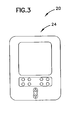
装置20は、陰極32と陽極34での接触反応を通して燃料電池30で発生される電気で駆動される。小型または携帯用の燃料電池30で操作される最適な装置の事例としては、携帯電話、携帯情報端末(PDA)、ラップトップコンピュータ、ポケットベル、ラジオおよびバッテリーによって伝統的手法で駆動される他の電子装置が含まれる。燃料電池30で駆動される適当な装置20の特殊な構成例については図2、3に図示される。図2には、装置20が図示されており、特に携帯電話22が示されており、図3には装置20としての携帯情報端末(PDA)24が図示されている。
The
燃料電池には5つの周知のタイプのものがあり、 燃料電池30はこれらのいずれかのタイプから選択されるであろう。陽子交換膜の燃料電池(PEMFCs)は、固体ポリマ電解質を含んでいる。この燃料電池は低温動作タイプであり、電力が必要となると電力シフトを満たすために急速にそれらの出力を変える能力を備えた高電力密度により、乗り物用の動力やビルなどの設備の同様に静止したアプリケーションにおいて理想的に使用される。PEM燃料電池は、燃料として水素を使用する。燃料源としてメタノールに存在する水素を使用するダイレクト・メタノール燃料電池は、PEM燃料電池のタイプの一つである。アルカリ燃料電池(AFCs)は、液体アルカリ電解液を含んでおり、主として宇宙任務アプリケーションで使用されてきた。りん酸燃料電池(PAFCs)は、燐酸電解質を利用しおり、現在は商業発電用に使用されている。溶融炭酸塩燃料電池(MCFCs)は、炭酸塩塩電解質を含んでおり、約650℃の運転温度で溶融状態になる。固体酸化物燃料電池(SOFCs)は、セラミックの電解質の材料を使用しており、約1000℃で動作する。MCFCsとSOFCsの双方とも燃料として一酸化炭素を使用することができる。しかしながら、これらの5つのタイプの燃料電池は本発明のフィルタ組立体の使用に適しているが、好ましい燃料電池としては、万能であり小型あるいは携帯用の燃料電池として容易に利用可能であるPEM燃料電池が良い。
There are five well-known types of fuel cells, and the
好ましい実施形態では、燃料電池30は陽極燃料として水素を使用する。水素燃料は、水素(すなわち、水素ガス)が直接的に供給されるか、または代替の源(すなわち、メタノール)として陽極34に提供されるであろう。燃料またはメタノールとして水素を使用するか否かに関係なく、いかなるタイプの水素燃料電池も陰極側に配置される本発明のフィルタ組立体の利益を得るであろう。ダイレクト・メタノール燃料電池または液体メタノール燃料電池と呼ばれる電池は、陰極側の本発明のフィルタ組立体と陽極側に配置される本発明のフィルタ組立体から利益を得るであろう。
In a preferred embodiment, the
ダイレクト・メタノール燃料電池が図1に図示される。システムに使用される特定の燃料電池によって、メタノール源が純粋なメタノールでない場合もあり、むしろ水に希釈されることで、20〜50%のメタノール希釈溶液であり、他にはより希釈されるかより濃縮された溶液を使用することができる。 A direct methanol fuel cell is illustrated in FIG. Depending on the specific fuel cell used in the system, the methanol source may not be pure methanol, but rather is diluted in water to give a 20-50% methanol dilute solution, otherwise more dilute. A more concentrated solution can be used.
水素燃料を提供するメタノール44は、燃料電池30の陽極34に液体として通常供給される。周囲空気または別の酸素または酸化剤源42が燃料電池30の陰極32に供給される。酸素は自然に陰極32に拡散されるか、またはポンプで送られるか(例えば、コンプレッサーまたはポンプ装置により)、例えば容器入りの源として提供される。水素(メタノールからの)と酸素は、夫々陽極34と陰極32の電極に接触し、電気と熱を引き起こし主要な副産物として水を作り出し、電極間で電圧を発生させる。75%の燃料利用効率が一般的であり、その利用は化学量論(stoichiometric)レベルの3倍である。すなわち、75%の燃料利用効率レベルでは、例えば25%の燃料の損失は陰極で交差するガスフローボリュームの燃料のために消費される。制御下では90%の燃料利用効率レベルが可能であることが公表されているが、このような燃料利用効率のレベルは、陰極ガスレベルが化学量論(stoichiometric)の2倍となることも公表されている。90%よりも大きいレベルおよび化学量論が2倍以下のレベルに達するものと予想される。
燃料電池30は、水素原子が陽子と電子に分離することを引き起こす触媒を使用し、それぞれが陰極で異なった経路を取るようにする。陽子は電気的な接触状態で配置された陰極32と陽極34との間の電解質35を通り抜ける。電子は、有益な電流(I)を発生し、この電流は装置20のエネルギ源として使用され、水素陽子と酸素とが結合して陽極に戻る前に装置20で水を形成する。
The
図1で見られるように、第1のフィルタ組立体100は燃料電池30の陽極34側に配置されており、第2のフィルタ組立体200が陰極32側に配置されている。
As seen in FIG. 1, the
陰極側のフィルタ組立体
次に、図5から図8を参照すると、第1のフィルタ組立体100の様々な実施形態が図示されている。第1のフィルタ組立体100は燃料電池30の酸化剤側面に配置されており、周辺環境となる周囲空気と燃料電池の陽極32の間において選択的に透過を許容する透過形バリアを形成している。第1のフィルタ組立体100は、陰極32への酸素の通過を選択的に許容するが陰極32に達する微粒子の通過を禁止することで微粒子が陰極32に到達しないようにする。同時出願の米国特許出願番号09/832, 715、09/879, 441,、09/122, 647および10/241, 117と米国特許第6,432, 177および第6,638, 339(ダラス他)(参照のためにここに取り入れられる開示)において記述されるように、燃料電池陽極は入って来る空気か酸素の流れで引き起こされる微粒子と化学汚染物質によって劣化されやすい。第1のフィルタ組立体100は、陰極32から離れている水の動きを調節する。
Cathode Side Filter Assembly Referring now to FIGS. 5-8, various embodiments of the
第1のフィルタ組立体100の第1の実施形態は、図5と図6Aで図示されている。組立体100は、吸着材材料114をケースに入れるための膜112を含み、膜の両側で空気の通過を可能にしている。膜の反対側112には接着性の構成120(図6A)が設けられる。この接着性の構成120は、燃料電池30の上でフィルタ組立体100を適切な位置に固定するための取り付け構造を提供する。図示の実施形態によれば、接着性の構成は、接着性の層122A、122Bとをサンドイッチにするキャリア121を備えた多重積層構成である。適当なキャリア121は剛性をフィルタ組立体100に提供できるPETである。図6Aから分かるように、フィルタ組立体100は吸着材材料114へのアクセスを可能にするために接着性の構成120によって形成される通気口115を含み、この構成120を通して空気または他のガスの流れを抑制する。陰極32で拡散する酸素量と陰極32からの水の量の全体的なレートに影響を及ぼしかつ最適化するように通気口115のサイズを調整できる。膜材料(同様か膜112とは異なる)を、接着性の構成120と吸着材材料114の間に配置することができ、このような膜は積層されるかまたは別の方法で吸着材114に付けられるであろう。この膜材料は濾過作用を増加させ、親水を加えるかまたは通気口115によって形成されたプレナムを変更するであろう。
A first embodiment of the
フィルタ組立体100の第1の実施形態の代替の構成が図6Bにおいてフィルタ組立体100'として図示される。この組立体100'は吸着材材料114をケースに入れるための膜112を含み、膜の反対側には接着性の構成120'が設けられる。追加の膜材料(不図示)は、接着性の構成120'の間に配置されて、吸着材材料114を横断するように延設されるであろう。剛性をフィルタ組立体100'に対して与えるために接着性の構成120'は多重積層構成であるが、フィルタ組立体100'を燃料電池30に固定するためのメカニズムは備えていない。構成120'は膜112にキャリア121を接着する1つの接着性の層122Bと、吸着材114とを有する。フィルタ組立体100'は燃料電池30の上のいかなる適切な位置に対して固定する取り付け構造となる第2の接着性の構成130を含む。図示の実施形態では、接着性の構成130は接着性の層132A、132Bとサンドイッチするキャリア131を含む多層の構成である。図6Aのフィルタ組立体100と同様に、図6Bのフィルタ組立体100'は接着性の構成120'で形成される通気口を含み、吸着材材料114へのアクセスを可能とするとともに、構成120'により空気の流れを規制し他のガスが通過しないように構成されている。
An alternative configuration of the first embodiment of
これらのフィルタ組立体100、100'において膜112はガスの分子の通過を許容するが液体と微粒子材料の通過を一般的に禁止する。膜112の適当な膜材料は、繊維状織物状材料、非織物状材料、紙、セルロース系材料またはガラス物質等があるがこれらには限定されない。膜112には疎水性、親水性、疎油性(疎油性)の材料が良いが、膜112はこれらの特性のいずれかを備える必要はない。膜材料は必要な疎水性、親水性、疎油性(疎油性)の特性を提供するために後処理されるであろう。しかしながら、望ましい膜112は拡張された四フッ化エチレン樹脂(PTFE)などのように疎水性な材料から作られると良い。膜112のための他の適当な材料としてはポリフッ化ビニリデン(PVDF)とポリプロピレン(PP)が含まれる。適当な拡張されたPTFE膜に関する事例としては、87ミクロンの厚さで0.1ミクロンの孔を穿設した「MD5834」と、87ミクロンの厚さで0.7ミクロンの孔を穿設した「EN 0701417」と、87ミクロンの厚さで1ミクロンの孔を穿設した「EN 0701552」と、200ミクロンの厚さで0.35〜0.4ミクロンの孔を穿設した「EN 0701405」と、250ミクロンの厚さで0.35ミクロンの孔を穿設した「EN 0701341」とがあり、これらはドナルドソン カンパニー インクから入手可能である。適当なポリプロピレン膜は、87ミクロンの厚さと0.1ミクロンの孔を穿設している「EN 0701516」である。
In these
フィルタ組立体100、100'の双方において、収着剤材料114は膜112を通り抜ける炭素ベースのVOCsやアンモニアおよびSO2などのような様々なガス分子を吸着する。収着剤材料114は永久に有害な汚染物質を保持するか、あるいは時間経過とともに汚染物質を放出するであろう。
In both
適当な収着剤材料114としては、活性炭、活性アルミナ、モレキュラーシーブ、イオン交換樹脂、他の機能的な樹脂と高分子、珪藻土、シリカゲルおよび粘土が含まれる。収着剤材料は、選択吸着または吸着反応を可能にするコーティング、添加物、含浸剤または他の処理が施されるであろう。含浸剤には水か有機溶液が使用されることで飽和された無機材料が含まれる。
1つ以上の収着剤材料114がフィルタ組立体で使用されるであろう。例えば活性炭の材料は炭化水素、酸性ガス(SO2などの)およびベースガス(アンモニアなどの)を吸着するのに使用され、あるいはシリカゲルか他の乾燥材料が陰極32からシステム10の外部まで使用され、接触反応の副産物である水の通過を禁止するであろう。この水の吸着材要素は水を吸着するか、またはシステム10からの外部に水が退出(しずく、漏出などによる)しないようにする。水の吸着材要素の適当な材料はシリカゲルが挙げられる。いくつかの実施形態では、水の吸着を行うよりも、陰極32において燃料電池30から水を調節下で放出することで指定されたレベルに相対湿度を維持するほうがむしろ必要となるかもしれない。陰極32における必要なレベルの相対湿度は、通常少なくとも50%であり、60〜100%の範囲となる。いくつかの構造では、炭素材料を設けることで特に水の調節特性が提供される結果、乾燥剤または他の材料を十分な水の調節ために設ける必要がなくなる場合がある。
One or
収着剤材料114を提供するためには様々な方法を使用することができる。一つの方法によれば、収着剤材料114を膜112などの基材の上に離散的なパターンで配置することができる。収着剤材料114は、ステンシル塗りタイプの工程で堆積する吸着スラリーとして形成できる。例えば、米国特許第5,869, 009号(Bellefeuille他)によれば、収着剤の材料を堆積させる工程が教示されるので、ここに参照のために記載する。別の方法によれば、収着剤材料114の離散的な断片を形成するように吸着材または吸収性材料のシートの形状を変える(すなわち、型抜き加工で)ことができる。続いて、これらの離散的な断片は膜112または他の多孔性のキャリアの材料に適用される。収着剤材料114およびフィルタ組立体100、100'のための他の製造方法も可能である。
Various methods can be used to provide the
図5、図6Aおよび図6Bに図示したフィルタ組立体100、100'は薄い形状を備えており、すなわち膜112、吸着材材料114およびいかなる他の層も多くの厚みを占有しない。図5、図6Aおよび図6Bに図示される構成によれば通常約0.25〜3mm、通常約0.75mmの厚みを備える。さらに、フィルタ組立体100、100'は膜112と吸着材114とにより形成される一般に柔らかく適合できる構造を有しており、接着構造120、120'により幾分かの剛性が提供される。
The
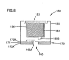
図7、図8において フィルタ組立体100の第2の実施形態がフィルタ組立体150として図示されている。第1のフィルタ組立体150は、環境と燃料電池陽極32との間で選択的な透過形バリアを形成することで、それを通してガス(酸素などの)の通過を許容するが、VOCs、酸性ガス、ベースガスおよび微粒子汚染物質の通過を許容しないように構成される。また、第1のフィルタ組立体150は陰極32から離れる水の動きを調節する。
7 and 8, a second embodiment of the
フィルタ組立体150は、外部のハウジング155を有し、これにより組立体150の総合的な物理的な機械構造が提供される。通常、ハウジング155はプラスチック製である。ハウジング150の中には膜162と吸着材材料164が保持される。膜162はハウジング155の上に一般的に配置されることになるが、膜162の保護のために凹状に設けられる場合もある。吸着材164は、ハウジング155のポケット156の中に保持される。組立体150は、燃料電池30の上の適切な位置に固定するための接着性の構造170を含む。図示された実施形態では、接着性の構造は、キャリア171をサンドイッチにする接着性の層172A、172Bを備えたは多重積層構成である。適当なキャリア171はポリエチレン・テレフタレート(PET)である。さらに、構造170はそれを通して空気または他のガスの流れを抑制する。
The
接着性の構造170とともにハウジング155は空気流路165の広がりをフィルタ組立体150の外部から吸着材164まで形成している。流路165は流路壁の一部が接着性の構造170によって形成されている状態で、ハウジング155の中に成形されるねじれた流路となっている。
接着性の構造170において、開口が流路165の第1の端部165Aに形成される。流路165の第2の端部165Bは吸着材164に近く近接されて配置される。
The
In the
フィルタ組立体100で述べたように、フィルタ組立体150は陰極32と外部の大気の間の通過を提供する開口または通気口を形成するように配置される。望ましくは、すべての空気か他の酸化剤源が陰極32に達するように開口または通気口を通り抜けるように構成されると良い。
As described with
フィルタ組立体150は、陰極に向かって空気や酸素源または他の望ましいガスの分子の通過を許容するが、微粒子と燃料電池性能に影響するであろうガスの化学汚染物質の通過は禁止する。
The
膜162はそれを通してガスの分子の通過を許容するが、微粒子汚染物質の通過を禁止する。膜162のための適当な材料は、繊維状織物状材料、非織物状材料、紙、電池ロース材料またはガラス物質が含まれる。膜162は、疎水性、親水性、疎油性の材料であるが、これらの特性のどれかを必ずしも備える必要はない。しかしながら好ましい膜162は、広げられた四フッ化エチレン樹脂(PTFE)などのように疎水性であると良い。膜162のための他の適当な材料は、ポリフッ化ビニリデン(PVDF)とポリプロピレン(PP)とが含まれる。
The
フィルタ組立体150は重合の開いたスクリーン、織物状材料または非織物状材料の層などのような追加層の材料を含むであろう。第1のフィルタ組立体150の層は、吸着材164を含む十分に目の細かい織物または非織物状材料であって、ガス(酸素などの)の通過を許容するタイプであると良い。層は材料の必要な特性に依存して、単一か多重層として形成させることができる。
The
吸着材164は、酸素と窒素などのガスの通過を許容するが、炭化水素(VOCs)、酸性ガス(例えばS02, H2S, C12, NOx)およびベースガス(例えばアンモニア)を吸着する。吸着材164は永久に汚染物質を保有するかまたは時間がたつにつれて汚染物質を放出するであろう。また、吸着材164は陰極32に近づきまた離れる水の蒸気を調節する。
The adsorbent 164 allows passage of gases such as oxygen and nitrogen, but adsorbs hydrocarbons (VOCs), acid gases (eg, S02, H2S, C12, NOx), and base gas (eg, ammonia). The adsorbent 164 will either permanently hold the pollutant or release it over time. Also, the adsorbent 164 regulates the water vapor that approaches and leaves the
吸着材164のための適当な材料は、活性炭、活性アルミナ、モレキュラーシーブ、イオン交換樹脂、他の機能的な樹脂と高分子、珪藻土、シリカゲルまたは粘土が含まれる。吸着材の材料は、選択吸着か反応を行えるようにコーティング、添加物、含浸剤または他の処理が施されるであろう。含浸剤には水か有機溶液を使用して飽和された無機材料が含まれる。一つ以上の材料が吸着材164で使用されるであろう。 Suitable materials for the adsorbent 164 include activated carbon, activated alumina, molecular sieves, ion exchange resins, other functional resins and polymers, diatomaceous earth, silica gel or clay. The adsorbent material may be subjected to coatings, additives, impregnants or other treatments to allow selective adsorption or reaction. Impregnating agents include inorganic materials saturated using water or organic solutions. One or more materials will be used in the adsorbent 164.
吸着材材料164を提供するために様々な方法を使用することができる。一つの方法によれば、吸着材粒子の一固まりが材料の固まりを形成するように成形される。粒子は重合バインダーまたは他の方法によって一緒に保持されるであろう。成型された吸着材の材料の様々な構造および製造方法は、米国特許第6,146,446号(Tuma他)と第6,168,651(Tuma他)と第6,491, 741(Tuma他)で開示されているので、ここに参照として記載する。
Various methods can be used to provide the
流路165は、またそれを通してガスの通過を許容するがガスの拡散を制限することにより、流路165は陰極32への酸素などのガスの拡散レートをバッファリング機能を果たす。同様に流路165は、それを通して蒸発している水の通過を許容するが水蒸気の拡散を制限する。このような方法により、流路165は陰極32から離れている水の拡散レートをバッファリングする機能を果たすので、陰極32における必要な相対湿度が維持される。陰極32に対する酸素の拡散レートと陰極32から離れる水の総合的なレートに影響するように流路165(長さ、断面積、幾何学形状など)の総合的なサイズを調整することができる。米国特許第4,863, 499号(Osendorf)、第 5,997,614号(Tuma他)と第6,491,741号(Tuma他)であって、参考のために記載した各公報には、様々な形式のフィルタ組立体150に組込むのに適当な種々のねじれた流路が記述されている。
The
図9に、第1のフィルタ組立体100の第3の実施形態がフィルタ組立体180として図示されている。フィルタ組立体180は、環境と燃料電池陽極32との間で選択的な透過形バリアを形成することで、それを通してガス(酸素などの)の通過を許容するが、VOCs、酸性ガス、ベースガスおよび微粒子汚染物質の通過を許容しないように構成される。また、フィルタ組立体180は陰極32から離れる水の動きを調節する。
In FIG. 9, a third embodiment of the
フィルタ組立体180は、電池に入れる静電気か膜の濾過媒体196と保護的な粗めの織物192の二つの層の間に設けられる吸着材要素194を有する。特に吸着材要素194は濾過媒体196a、196bでカバーされており、続いて保護的な粗めの織物192a、192bで覆われる。
The
フィルタ組立体100とフィルタ組立体150と同様に、フィルタ組立体180は陰極32と大気の間でシステム10の通気を可能にする通気口か開口の上に配置される。望ましくは、すべての空気か他の酸化剤が陰極32に達するようにこの通気口か開口を通り抜けると良い。
Similar to filter
また、保護的な粗めの織物192は、それを通してガスの分子が通過することを許容するが微粒子汚染物質の通過は禁止する。一般に粗めの織物192を通る圧力降下は最小限になる。保護的な粗めの織物192の適当な材料は、繊維状織物状材料、非織物状材料、紙かセルロース系材料またはガラス物質が挙げられるが、これらに限定されない。粗めの織物192には疎水性、親水性、疎油性の特性を備えると良いが、必ずしもこれらの特性を備える必要はない。好ましい保護的な粗めの織物192は、織られたポリエステル織物であって、ドナルドソン カンパニーから名称「EN0701457」として入手可能な織物がある。また、他の粗めの織物192は、ドナルドソン カンパニーから名称「EN0701232」として入手可能な織物がある。
The protective
静電気の媒体または膜196により吸着材194が保持されそれを通してガスの分子の通過を許容するが微粒子汚染物質の通過を禁止するように構成される。媒体か膜196の適当な材料としては、繊維状織物状材料、非織物状材料、紙、セルロース系材料またはガラス物質が挙げられるが、これら以外にも使用可能である。層196を形成するために多重層か材料が積層されるかまたは別の方法が採用されるであろう。好ましい媒体または膜196は、アクリル/ポリプロピレン・ブレンドである。
An adsorbent 194 is held by an electrostatic medium or
吸着材194は、吸着材114と吸着材164と同様であるが、炭化水素(VOCs)、酸性ガスおよびベースガスを吸着するが、酸素と窒素などのガスの通過を許容する。
フィルタ組立体180が、駆動されるか加圧された酸化剤流動(例えばポンプで送られた空気)を利用する燃料電池組立体により適している。なぜならばこの種の組立体は酸素を陰極に供給するために拡散に依存しないからである。この組立体180に関する詳細については、例えば米国特許第5,997,618号および第6,077,335号(Isogawa他)に見ることができるので、参照のためにここに記載する。
図5、図6A、図6B、図7、図8および図9を参照して述べた第1のフィルタ組立体100の実施形態では、フィルタ組立体は単一の単体であった。ここで、フィルタ組立体が多重単位で構成可能であることが分かる。例えば、それを通してガス拡散を供給するがそれを通して微粒子を禁止する第1のユニットが通気口の上に配置されるであろう。第2のユニットは、例えば化学汚染物質を吸着して湿度を規制するために吸着材の材料を有しており、通気口から遠く離れた位置に配置されるであろう。空気入口となる通気口から離れた状態で配置される吸着材部分の事例は、米国特許第5,876,487号(Dahlgren他)、第6,143,058号(Dahlgren他)、第6,214,095号(Logan他)に開示されているのでここに記載する。
In the
陽極側の上のフィルタ組立体
再び図1を参照して、燃料電池30の陽極側の面において第2のフィルタ組立体200が含まれる。第2のフィルタ組立体200は、それを通して酸素、窒素、二酸化炭素などのようにガスの分子の通過を許容するが、それを通してメタノールなどの液体を許容しないように組み立てられ配置される。第2のフィルタ組立体200は一般的に、燃料電池30から燃料、水などが通過することは許容しないが大気中の材料と燃料電池反応副産物の通過を許容する。
Filter assembly on the anode side Referring again to FIG. 1, a
図4は燃料電池の一部の拡大図を図示しており、特に容器内のメタノール源50について第2のフィルタ組立体200とともに図示されている。容器50は、液体メタノールを貯蔵して陽極34に当接するように構成され、任意に陽極34は容器50の内部容積部を形成するための壁を形成する場合もある。容器50は、内部の表面51と外部の表面53を有しており、液体メタノール44、ガス状の二酸化炭素46および他のガスの材料の容積部を形成する。二酸化炭素46は、陽極34での反応の副産物である。容器50には、少なくとも開口部55が形成されており、通気口を容器50の内部の容積部とシステム10の外部との間に形成する。図4に図示した特定の実施形態では、容器50は3つの開口部55を含む。容器50中のメタノールを使用するために、容器50はメタノールの補充のための通気口を含む場合もある。また、陰極34との関係において、容器50は取り外し可能または取替え可能に構成することができる結果、使用済の容器50が新しい完全な容器50と取り替え可能となる。
FIG. 4 illustrates an enlarged view of a portion of the fuel cell, particularly with the
容器50の開口部55を横切るように配置される第2のフィルタ組立体200により、選択的な透過形バリアがメタノール44とシステム10の外部との間に形成される。第2のフィルタ組立体200は、望ましくは酸素、窒素、アルゴンおよび二酸化炭素などのガスの分子の通過を許容すると良い。また、蟻酸とホルムアルデヒドなどのような陽極34での反応副産物は第1のフィルタ組立体100に浸みわたる。第2のフィルタ組立体200は、容器50の内部の表面51または外部の表面53のいずれかに固定される。
A selective permeable barrier is formed between the
第2のフィルタ組立体200の好ましい構成としては、一般的に疎水性又は疎油性あるいは双方の特性の材料から作られたラベルフィルタと呼ばれる精密濾過膜である。疎水性又は疎油性あるいは双方の特性を有する材料は、それを通してガスの分子の通過を許容するが、それを通しての液体メタノールなどの液体の通過を許容しない特性を有する。これらの適当な材料は、広げられた四フッ化エチレン樹脂(PTFE)か、ポリプロピレン、ポリフッ化ビニリデン(PVDF)かねじれている毛穴を有する材料が挙げられる。材料に疎水性又は疎油性特性を増加させるために、後処理か他のコーティングを施す場合がある。
A preferred configuration of the
PTFEは、ドナルドソン カンパニー インクから名称「Tetratex」として入手可能であり、またW.L.Goa & Assoc社から名称「Gore Tex」として商業的に利用可能である。PTFEは、種々の厚さおよび寸法で利用可能である。第2のフィルタ組立体のための疎水性又は疎油性あるいは双方の特性の材料の好ましい厚みは約12〜260ミクロンである。このような厚み材料においては、0.1〜2ミクロンの孔が適しており、さらに孔は0.05ミクロンおよび0.01ミクロンの孔が最適である。 PTFE is available from Donaldson Company Inc. under the name “Tetratex” and is commercially available from W.L. Goa & Assoc under the name “Gore Tex”. PTFE is available in various thicknesses and dimensions. The preferred thickness of the hydrophobic or oleophobic material or both for the second filter assembly is about 12 to 260 microns. In such thick materials, 0.1 to 2 micron pores are suitable, and 0.05 and 0.01 micron pores are optimal.
適当な広げられたPTFE膜に関する特定な事例としては、0.1ミクロンの無数の孔を穿設した厚さ87ミクロンの「MD 5834」、0.2ミクロンの無数の孔を穿設した厚さ87ミクロンの「MD 5897」、0.7ミクロンの無数の孔を穿設した厚さ87ミクロンの「EN 0701417」、1ミクロンの無数の孔を穿設した厚さ87ミクロンの「EN 0701552」、0.35〜0.4ミクロンの無数の孔を穿設した厚さ200ミクロンの「EN 0701405」、0.35ミクロンの無数の孔を穿設した厚さ250ミクロンの「EN 0701341」があるが、これらはドナルドソン カンパニー インクから入手および使用可能である。適当なポリプロピレン膜の一例は、0.1ミクロンの無数の孔を穿設した厚さ87ミクロンの「EN 0701516」がある。適当なPVDF膜は、0.1ミクロンの無数の孔を穿設した厚さ87ミクロンの「MD 5915」がある。「EN 0701341」と「EN 0701516」については、疎油性処理を施すことでメタノールを弾く特性を増加させることができる。 Specific examples of suitable expanded PTFE membranes include 87-micron-thick “MD 5834” with an infinite number of 0.1-micron holes and 87-micron-thick “with an infinite number of 0.2-micron holes”. "MD 5897", 87 microns thick "EN 0701417" with countless holes of 0.7 microns, "EN 0701552" with countless holes of 1 micron, countless numbers of 0.35 to 0.4 microns There are "EN 0701405" with a thickness of 200 microns, and "EN 0701341" with a countless number of holes of 0.35 microns, available and available from Donaldson Company Inc. It is. An example of a suitable polypropylene membrane is "EN 0701516" having a thickness of 87 microns with an infinite number of holes of 0.1 microns. A suitable PVDF membrane is "MD 5915" having a thickness of 87 microns with countless holes of 0.1 microns. With respect to “EN 0701341” and “EN 0701516”, the characteristics of repelling methanol can be increased by performing oleophobic treatment.
望ましくは、第2のフィルタ組立体200は容器50(図4を参照のこと)の全体の開口部55を覆うための一体的なシールを提供するように、容器の内部の表面51または外部の表面53にまで延設されると良い。望ましくは第2のフィルタ組立体200は、開口部55の先から約1〜10mm分延設されると良い。
Desirably, the
第2のフィルタ組立体200は、一般に接着剤を用いて容器50の内部の表面51または外部の表面53に固定される。内部の表面51に第2のフィルタ組立体200が固定される場合には、液体メタノールに接触するので、接着剤は組立体の寿命の間はメタノールに対する抵抗力を備え、悪化せず、かつ溶解してはならない。フィルタを容器50の上の適切な位置に接着する前に、リリースライナーか他の剥離層をフィルタ組立体200に敷設しておき、接着の直前にこれらのリリースライナーを剥がすように構成できる。また、容器50に第2のフィルタ組立体200を固定するための、他のメカニズムを使用することができ、例えば、熱ボンディング(例えば超音波ボンディングまたは熱)または機械的手段によってフィルタ組立体200を固定することができるであろう。
第2のフィルタ組立体200は、吸収剤または吸着材の材料を含むであろう。このような収着剤の材料は、フィルタ組立体200が大気中を通り抜けるためではなく、むしろ材料で吸着するように設けられる。例えば、陽極34での反応による蟻酸とホルムアルデヒドの副産物は収着剤の材料によって吸着されるだろう。すべての収着剤の材料は永久に汚染物質を保持するか、または時間経過とともに汚染物質を放出するであろう。収着剤の材料は、コーティング、添加物、含浸剤のための後処理がなされて、汚染物質と反応した後にそれらと中和するように準備される。適当な収着剤の材料としては、活性炭、活性アルミナ、モレキュラーシーブ、イオン交換樹脂、他の機能的な樹脂、高分子、珪藻土、珪石または粘土が含まれる。全ての収着剤の材料は、望ましくはケースに入れられるかまたは疎水性の材料などにより別の方法で囲まれる。
The
フィルタ組立体100、100'、150は円形または筒状のものとして図示されているが、第1のフィルタ組立体と第2のフィルタ組立体は、長方形、八辺形、星形、楕円形および同様の全体形状を有するか、これらの適当な幾何学上の輪郭を組み合わせた形状を有しても良い。
Although the
さらに、フィルタ組立体100、100'、150は単一の通気口115、165を備えるものとして図示されているが、 第1のフィルタ組立体または第2のフィルタ組立体は多重通気口または複数の通気口を備えることも理解されよう。
Further, although the
フィルタ組立体の様々な特定な実施例を以下に列記する。 Various specific examples of filter assemblies are listed below.
模範的なフィルタ組立体
実施例1. 実施形態と同様の図5、図6Aで図示した第1のフィルタ組立体100が提供される。ベース材料にPTFEとポリエチレンとを飽和させた活性炭材料114がシート材料として準備され、これを直径8.5mmの円形にプレス加工する。 吸着材114は広げられたPTFE 112の層で覆われ、約200ミクロンの厚みを有し、約0.35ミクロンの無数の孔を穿設している。このようなPTFEの材料は、ドナルドソン カンパニー、 インクから名称「EN0701405」として入手および利用可能である。層にされた構成は11.9mmの直径の円形にプレス加工される。感圧接着剤がPTFEの反対側に設けられ、6.4mmの内側の直径を持っている輪状の接着性の領域を提供される。フィルタ組立体の総合的な厚みは約0.75mmであった。無シリコンのリリースライナーが感圧接着剤の上に設けられた。ここに記載した工程の順序は、他にも可能である。
Exemplary Filter Assembly Example 1. A
このようにして製造されたフィルタ組立体100が名称「Adsorbent Breatherフィルター」としてドナルドソン カンパニー インクから商業的に利用可能である。あるいは、「ABF」、「ABFフィルタ」として直径の10〜100mmのものがドナルドソン カンパニー インクから利用可能である。これら以外にも、様々な幾何学形状品も利用可能である。
The
実施例2.実施形態と同様の図7、図8に図示した第1のフィルタ組立体150が提供される。活性炭は、吸着材質量164を提供するためにタブレットに成型される。開口面に対向して成型される拡散流路165を有する5面の直角のプラスチックのハウジング155の中にタブレットが配置された。約25ミクロンの厚みを有し、約1.5ミクロンの無数の孔を穿設した1片のPTFE膜162がタブレット上に置かれた。感圧接着剤が拡散流路165を形成した側のハウジングの側面に付着されることで、流路の端部165Aを塞がない状態にされた。ここに記載した工程の順序は、他にも可能である。
Example 2 A
このようなフィルタ組立体150は、名称「Adsorbent Breather組立体」としてドナルドソン カンパニー インクから商業的に利用可能である。また、「ABA」、「ABAフィルタ」であって、4〜50mm(幅、長さおよび高さ)の寸法のものがドナルドソン カンパニー インクから利用可能である。円筒の「ABA」であってフィルタ直径が4〜50mm、4〜15mm(高さ)の寸法のものも利用可能である。様々な幾何学形状品も利用可能である。
Such a
実施例3.実施形態と同様の図9に図示した第1のフィルタ組立体180が提供される。連続したビード状活性炭は、吸着材質量194を得るためにプレス加工される。吸着材質量194は、表裏それぞれの側がアクリル/ポリプロピレン多重積層の静電気の濾過媒体196でカバーされる。織られたポリエステル粗めの織物192の厚さが約127ミクロンの層が、濾過媒体層の表裏それぞれの側の上に置かれた。濾過媒体層と粗めの織物の縁は超音波溶接によって封鎖され、吸着材質量194の周りの周囲にシールが形成された。
Example 3 FIG. A
このようなフィルタ組立体180は、名称「Adsorbent Recirculationフィルタ」として、ドナルドソン カンパニー インクから商業的に利用可能である。また、「ARF」、「ARFフィルタ」として、4〜100mm(幅と長さ)の寸法であり、約2〜20mmの総合的な厚み、約1〜5mmのシールの外側の周囲厚みを有するものがドナルドソン カンパニー インクから利用可能である。様々な幾何学形状品も利用可能である。
Such a
実施例4 第2のフィルタ組立体200の特定の構成が提供される。約200ミクロンの厚みを有し、約0.35ミクロンの無数の孔を穿設した、広げられたPTFE膜112を、4.4mmの直径を有する円形にプレス加工する。
Example 4 A specific configuration of the
このようなPTFEの材料は、ドナルドソン カンパニー、インクら名称「EN0701405」として利用可能である。感圧接着剤は、1.5mmの内側の直径を有する輪状の接着性の領域を提供するために円の周辺に付着される。このフィルタ組立体の総合的な厚みは約0.75mmとなった。ここに記載した工程の順序は、他にも可能である。 Such PTFE material is available under the name “EN0701405” by Donaldson Company, Inc. The pressure sensitive adhesive is applied to the periphery of the circle to provide an annular adhesive area with an inner diameter of 1.5 mm. The total thickness of this filter assembly was about 0.75 mm. The order of the steps described here is possible in other ways.
このようなフィルタ組立体200は、名称「Standard Breatherフィルター」としてドナルドソン カンパニー インクから商業的に利用可能である。「SBF」、「SBFフィルタ」は直径の4〜100mmのものでありドナルドソン カンパニー インクから利用可能である。様々な幾何学形状品も利用可能である。
Such a
実施例5 吸着材の材料を含む適当な第2のフィルタ組立体200の特定の事例は、実施例1で記述されたABFフィルタである。
Example 5 A specific example of a suitable
以上の記述と事例によれば、燃料電池用のフィルタ組立体の広い範囲の特定の事例が提供された。上述の内容では本発明の多数の特性と本発明の利点を記載したが、しかしながら、本発明の構造の細部の構成および機能はほんの一例にすぎず、請求の範囲に記載される用語の広い一般的な意味合いから部品、機構および動作原理の変更が可能であることが理解されるべきである。 According to the above description and examples, a wide range of specific examples of filter assemblies for fuel cells have been provided. The foregoing describes a number of the characteristics and advantages of the present invention, however, the detailed structure and function of the structure of the present invention is only an example, and the broad general terms of the claims It should be understood that the components, mechanisms, and operating principles can be changed in a practical sense.
Claims (20)
(b) 前記酸化剤吸気口と前記陰極とに流体的に接続されるフィルタ組立体であって、
前記フィルタ組立体は、
(i) 少なくとも微粒子除去部材と化学物質吸着部材の少なくとも一つと、
(ii) 水をバッファリングするための水バッファ部材とを備え、
(c) 前記フィルタ組立体は、酸化剤が前記酸化剤吸気口を通過して入り前記フィルタ組立体を通り抜け、前記陰極からの水の蒸気が前記水バッファ部材により調節されることで必要な湿度レベルを維持できるように前記燃料電池に配置および構成されることを特徴とする燃料電池組立体。 (a) a portable fuel cell having a cathode fluidly connected to the oxidant inlet and the anode;
(b) a filter assembly fluidly connected to the oxidant inlet and the cathode,
The filter assembly includes:
(i) at least one of a particulate removing member and a chemical substance adsorbing member;
(ii) a water buffer member for buffering water,
(c) In the filter assembly, an oxidant enters through the oxidant intake port and passes through the filter assembly, and water vapor from the cathode is adjusted by the water buffer member, thereby requiring a required humidity. A fuel cell assembly arranged and configured in the fuel cell so as to maintain a level.
(i) 陰極と、
(ii) 陽極とを備え、
(iii) 前記陽極と流体的に接触する液体のメタノール源が、通気口を有する容器の中に溜液され、前記通気口は前記容器の内部と前記容器の外部の間を流体的に接触させるように構成され、
(b) 前記通気口の内部に配置されるフィルタ組立体は、前記容器の内部と前記容器の外部の間を流体的に接触させるように構成され、前記フィルタ組立体は選択的に透過する疎水性部材または疎油性部材の一方又は双方を備えることを特徴とする燃料電池組立体。 (a) Portable direct methanol fuel cells
(i) a cathode;
(ii) comprising an anode,
(iii) A liquid methanol source that is in fluid contact with the anode is stored in a container having a vent, and the vent is in fluid contact between the interior of the container and the exterior of the container. Configured as
(b) The filter assembly disposed inside the vent is configured to make fluid contact between the inside of the container and the outside of the container, and the filter assembly is selectively permeable hydrophobic. A fuel cell assembly comprising one or both of a conductive member and an oleophobic member.
Applications Claiming Priority (2)
| Application Number | Priority Date | Filing Date | Title |
|---|---|---|---|
| US43048302P | 2002-12-02 | 2002-12-02 | |
| PCT/US2003/038203 WO2004055930A2 (en) | 2002-12-02 | 2003-12-02 | Various filter elements for hydrogen fuel cell |
Publications (2)
| Publication Number | Publication Date |
|---|---|
| JP2006516352A true JP2006516352A (en) | 2006-06-29 |
| JP2006516352A5 JP2006516352A5 (en) | 2007-02-01 |
Family
ID=32595076
Family Applications (1)
| Application Number | Title | Priority Date | Filing Date |
|---|---|---|---|
| JP2004560346A Withdrawn JP2006516352A (en) | 2002-12-02 | 2003-12-02 | Various filter elements for hydrogen fuel cells |
Country Status (8)
| Country | Link |
|---|---|
| US (1) | US20040151966A1 (en) |
| EP (1) | EP1570537A2 (en) |
| JP (1) | JP2006516352A (en) |
| KR (1) | KR20050084115A (en) |
| CN (1) | CN1751407A (en) |
| AU (1) | AU2003302735A1 (en) |
| CA (1) | CA2507947A1 (en) |
| WO (1) | WO2004055930A2 (en) |
Families Citing this family (14)
| Publication number | Priority date | Publication date | Assignee | Title |
|---|---|---|---|---|
| US7211344B2 (en) * | 2003-05-14 | 2007-05-01 | The Gillette Company | Fuel cell systems |
| CN100369305C (en) * | 2004-12-30 | 2008-02-13 | 比亚迪股份有限公司 | A kind of fuel cell |
| US7648565B2 (en) * | 2005-07-13 | 2010-01-19 | Parker-Hannifin Corporation | Filter element |
| US8882874B1 (en) | 2005-10-13 | 2014-11-11 | Jonathan Cross | Flexible, multi-cartridge, reconfigurable/selectable air contaminant control system and method for fuel cells |
| DE102006002926A1 (en) * | 2006-01-20 | 2007-08-02 | Fraunhofer-Gesellschaft zur Förderung der angewandten Forschung e.V. | Direct oxidation fuel cell has fluid transfer using a diffusion process with a membrane structure |
| DE102007014046B4 (en) * | 2007-03-23 | 2011-07-28 | Fraunhofer-Gesellschaft zur Förderung der angewandten Forschung e.V., 80686 | Fuel cell and method for its production |
| EP2210302A4 (en) * | 2007-09-25 | 2012-12-05 | Bic Soc | Fuel cell cover |
| CN101953006B (en) * | 2008-03-31 | 2014-07-23 | 罗姆股份有限公司 | Fuel cell, and method for manufacturing the same |
| EP2703057A3 (en) * | 2012-09-03 | 2016-04-13 | Carl Freudenberg KG | Fluid cleaner |
| DE102013008389A1 (en) * | 2013-05-17 | 2014-11-20 | Mann + Hummel Gmbh | Filter element, in particular air filter element, and filter system with a filter element |
| CN110718722B (en) * | 2018-07-13 | 2022-01-25 | 宁德新能源科技有限公司 | Adsorption component and battery |
| US20220029187A1 (en) * | 2018-12-06 | 2022-01-27 | Widex A/S | A direct alcohol fuel cell |
| CN112531297A (en) * | 2019-08-27 | 2021-03-19 | 比亚迪股份有限公司 | Battery and battery pack |
| US20230290976A1 (en) * | 2022-03-11 | 2023-09-14 | Robert Bosch Gmbh | Chemical and electrochemical cell electronics protection system |
Family Cites Families (56)
| Publication number | Priority date | Publication date | Assignee | Title |
|---|---|---|---|---|
| US3847672A (en) * | 1971-08-18 | 1974-11-12 | United Aircraft Corp | Fuel cell with gas separator |
| US3812370A (en) * | 1971-09-07 | 1974-05-21 | Environment One Corp | Low cost portable room air cleaner |
| US3861894A (en) * | 1972-10-13 | 1975-01-21 | Bio Dynamics Inc | Portable clean-air generator |
| US3925043A (en) * | 1973-11-13 | 1975-12-09 | Environment One Corp | Low cost, efficient, general purpose air cleaner cartridge |
| SE419509B (en) * | 1976-08-10 | 1981-08-10 | Wennberg Flex Ake Ab | FOR CLEANING AIR IN WORKING ROOMS O DYL INTENDED DEVICE |
| US4080791A (en) * | 1977-01-03 | 1978-03-28 | Exxon Research & Engineering Co. | Fuel cell power generating stations |
| US4483694A (en) * | 1982-06-24 | 1984-11-20 | Tokyo Shibaura Denki Kabushiki Kaisha | Oxygen gas permselective membrane |
| JPS6171561A (en) * | 1984-09-14 | 1986-04-12 | Mitsubishi Heavy Ind Ltd | Composite plant of fuel cell |
| US4737173A (en) * | 1986-07-03 | 1988-04-12 | Amway Corporation | Room air treatment system |
| US4909815A (en) * | 1988-10-24 | 1990-03-20 | International Air Filter, Inc. | Mobile air cleaning apparatus |
| US5626820A (en) * | 1988-12-12 | 1997-05-06 | Kinkead; Devon A. | Clean room air filtering |
| US5013617A (en) * | 1989-12-29 | 1991-05-07 | International Fuel Cells Corporation | Air ejector system for fuel cell passivation |
| WO1991014496A1 (en) * | 1990-03-20 | 1991-10-03 | W.L. Gore & Associates, Inc. | An adsorbent assembly for removing gaseous contaminants |
| US5221586A (en) * | 1990-09-19 | 1993-06-22 | Ishikawajima-Harima Heavy Industries Co., Ltd. | Power generation system using fuel cells |
| US5238474A (en) * | 1990-10-19 | 1993-08-24 | Donaldson Company, Inc. | Filtration arrangement |
| JP3333877B2 (en) * | 1990-11-23 | 2002-10-15 | ビーエイイー システムズ マリン リミテッド | Application of fuel cell to power generation system |
| US5249948A (en) * | 1991-04-08 | 1993-10-05 | Koslow Technologies Corporation | Apparatus for the continuous extrusion of solid articles |
| US5189092A (en) * | 1991-04-08 | 1993-02-23 | Koslow Technologies Corporation | Method and apparatus for the continuous extrusion of solid articles |
| US5139546A (en) * | 1991-06-04 | 1992-08-18 | Novobilski Carl G | Nail vapor and dust collection and treatment device |
| US5156925A (en) * | 1991-10-09 | 1992-10-20 | Alcan International Limited | Hydrogen removal system for metal/air cell |
| US5372617A (en) * | 1993-05-28 | 1994-12-13 | The Charles Stark Draper Laboratory, Inc. | Hydrogen generation by hydrolysis of hydrides for undersea vehicle fuel cell energy systems |
| DE4322767C2 (en) * | 1993-07-08 | 1995-05-24 | Daimler Benz Ag | Device and method for starting a fuel cell vehicle |
| DE4322765C1 (en) * | 1993-07-08 | 1994-06-16 | Daimler Benz Ag | Dynamic power regulation system for vehicle electric drive unit - regulates power output delivered by fuel cell using correction of oxidant mass flow rate |
| US5376609A (en) * | 1993-08-23 | 1994-12-27 | Corning Incorporated | Activated carbon bodies having bentonite and cellulose fibers |
| US5773162A (en) * | 1993-10-12 | 1998-06-30 | California Institute Of Technology | Direct methanol feed fuel cell and system |
| DE4412451C1 (en) * | 1994-04-12 | 1995-09-28 | Daimler Benz Ag | Arrangement of a drive unit in an electric vehicle |
| DE4412450A1 (en) * | 1994-04-12 | 1995-10-26 | Daimler Benz Ag | Arrangement of a drive unit in an electric vehicle |
| SE9501369D0 (en) * | 1995-04-12 | 1995-04-12 | Curt Lindhe Konsult & Foervalt | Multiple filter unit |
| WO1997000717A1 (en) * | 1995-06-20 | 1997-01-09 | Donaldson Company, Inc. | Filter and method for making a filter |
| JP3519828B2 (en) * | 1995-08-30 | 2004-04-19 | 本田技研工業株式会社 | Fuel cell system |
| US5672399A (en) * | 1995-11-17 | 1997-09-30 | Donaldson Company, Inc. | Filter material construction and method |
| EP0788172B1 (en) * | 1996-02-05 | 2001-12-05 | Matsushita Electric Industrial Co., Ltd. | Fuel cell for mounting on equipment |
| US5792247A (en) * | 1996-04-26 | 1998-08-11 | Donaldson Company, Inc. | Integrated resonator and filter apparatus |
| US5928414A (en) * | 1996-07-11 | 1999-07-27 | W. L. Gore & Associates, Inc. | Cleanable filter media and filter elements |
| DE19701560C2 (en) * | 1997-01-17 | 1998-12-24 | Dbb Fuel Cell Engines Gmbh | Fuel cell system |
| JP3090088B2 (en) * | 1997-02-07 | 2000-09-18 | 富士電機株式会社 | Clean room fan filter unit |
| WO1998039081A1 (en) * | 1997-03-05 | 1998-09-11 | Air-Maze Corporation | Air cleaner element having incorporated sorption element |
| JPH1131519A (en) * | 1997-07-11 | 1999-02-02 | Toyota Autom Loom Works Ltd | Solid polymeric electrolyte type fuel cell system |
| US6013385A (en) * | 1997-07-25 | 2000-01-11 | Emprise Corporation | Fuel cell gas management system |
| US6075769A (en) * | 1997-11-26 | 2000-06-13 | Cisco Systems, Inc. | Method and apparatus for network flow control |
| US6007930A (en) * | 1998-05-06 | 1999-12-28 | Ford Global Technologies, Inc. | Method for initiating a fuel cell |
| DE19821952C2 (en) * | 1998-05-15 | 2000-07-27 | Dbb Fuel Cell Engines Gmbh | Power supply unit on board an aircraft |
| US6284397B1 (en) * | 1998-05-29 | 2001-09-04 | Ballard Power Systems Inc. | Rotary piston blower for supplying an oxidant stream to a fuel cell |
| US5997614A (en) * | 1998-07-13 | 1999-12-07 | Donaldson Company, Inc. | Filter with diffusion channel and methods of making and using the filter |
| US6190432B1 (en) * | 1999-02-26 | 2001-02-20 | Donaldson Company, Inc. | Filter arrangement; sealing system; and methods |
| DE19916386C2 (en) * | 1999-03-31 | 2001-10-31 | Mannesmann Ag | Fuel cell system and method for regenerating a filter element in a fuel cell system |
| US6316134B1 (en) * | 1999-09-13 | 2001-11-13 | Ballard Generation Systems, Inc. | Fuel cell electric power generation system |
| US6321637B1 (en) * | 1999-12-30 | 2001-11-27 | Honeywell International Inc. | Low-profile air filter module |
| DE10027350B4 (en) * | 2000-06-02 | 2010-05-12 | General Motors Corporotion, Detroit | Compressor arrangement for the operation of a fuel cell system and a method for cooling and / or sound insulation of a compressor assembly |
| US6309769B1 (en) * | 2000-06-30 | 2001-10-30 | Plug Power Inc. | Carbon monoxide filter layer |
| US6432177B1 (en) * | 2000-09-12 | 2002-08-13 | Donaldson Company, Inc. | Air filter assembly for low temperature catalytic processes |
| US6783882B2 (en) * | 2001-02-14 | 2004-08-31 | Ball Aerospace & Technologies Corp. | Method and apparatus for maintenance of fuel cell cathode air quality with breathable hydrophobic membrane air filter |
| US6780534B2 (en) * | 2001-04-11 | 2004-08-24 | Donaldson Company, Inc. | Filter assembly for intake air of fuel cell |
| US6797027B2 (en) * | 2001-04-11 | 2004-09-28 | Donaldson Company, Inc. | Filter assemblies and systems for intake air for fuel cells |
| US6783881B2 (en) * | 2001-04-11 | 2004-08-31 | Donaldson Company, Inc. | Filter assembly for intake air of fuel cell |
| US6951697B2 (en) * | 2001-09-11 | 2005-10-04 | Donaldson Company, Inc. | Integrated systems for use with fuel cells, and methods |
-
2003
- 2003-12-02 CA CA002507947A patent/CA2507947A1/en not_active Abandoned
- 2003-12-02 JP JP2004560346A patent/JP2006516352A/en not_active Withdrawn
- 2003-12-02 KR KR1020057010002A patent/KR20050084115A/en not_active Application Discontinuation
- 2003-12-02 AU AU2003302735A patent/AU2003302735A1/en not_active Abandoned
- 2003-12-02 CN CNA2003801094010A patent/CN1751407A/en active Pending
- 2003-12-02 US US10/727,027 patent/US20040151966A1/en not_active Abandoned
- 2003-12-02 EP EP03811665A patent/EP1570537A2/en not_active Withdrawn
- 2003-12-02 WO PCT/US2003/038203 patent/WO2004055930A2/en active Application Filing
Also Published As
| Publication number | Publication date |
|---|---|
| AU2003302735A8 (en) | 2004-07-09 |
| CN1751407A (en) | 2006-03-22 |
| US20040151966A1 (en) | 2004-08-05 |
| CA2507947A1 (en) | 2004-07-01 |
| AU2003302735A1 (en) | 2004-07-09 |
| KR20050084115A (en) | 2005-08-26 |
| WO2004055930A3 (en) | 2004-11-11 |
| EP1570537A2 (en) | 2005-09-07 |
| WO2004055930A2 (en) | 2004-07-01 |
Similar Documents
| Publication | Publication Date | Title |
|---|---|---|
| US5759712A (en) | Surface replica fuel cell for micro fuel cell electrical power pack | |
| EP1296400B1 (en) | Fuel cell power generation equipment | |
| KR100684223B1 (en) | Fuel cell | |
| US20060199061A1 (en) | Water management in bipolar electrochemical cell stacks | |
| US20060228606A1 (en) | Water management in monopolar fuel cells | |
| JP2006516352A (en) | Various filter elements for hydrogen fuel cells | |
| JPWO2005091410A1 (en) | Solid oxide fuel cell | |
| JP4810082B2 (en) | Fuel cell | |
| JP4611933B2 (en) | Fuel cell system | |
| JP5100640B2 (en) | MEA member and polymer electrolyte fuel cell | |
| US8968946B2 (en) | Fuel cell systems | |
| JP3744804B2 (en) | Polymer electrolyte fuel cell | |
| WO2007110941A1 (en) | Fuel cell | |
| WO2007055301A1 (en) | Fuel battery | |
| JP5003056B2 (en) | Fuel cell | |
| KR100718114B1 (en) | Fuel cell system comprising structure for supplying fuel in vapor phase | |
| US20100047642A1 (en) | Fuel cell | |
| JP2007095399A (en) | Fuel cell and electronic equipment for mounting the same | |
| JP2009238611A (en) | Mea member, fuel battery cell, and polymer electrolyte fuel battery | |
| JP2007134235A (en) | Fuel battery |
Legal Events
| Date | Code | Title | Description |
|---|---|---|---|
| A521 | Request for written amendment filed |
Free format text: JAPANESE INTERMEDIATE CODE: A523 Effective date: 20060322 |
|
| A521 | Request for written amendment filed |
Free format text: JAPANESE INTERMEDIATE CODE: A523 Effective date: 20061204 |
|
| A621 | Written request for application examination |
Free format text: JAPANESE INTERMEDIATE CODE: A621 Effective date: 20061204 |
|
| A761 | Written withdrawal of application |
Free format text: JAPANESE INTERMEDIATE CODE: A761 Effective date: 20070803 |