JP2006512099A - Composite vascular graft - Google Patents
Composite vascular graft Download PDFInfo
- Publication number
- JP2006512099A JP2006512099A JP2001507391D JP2001507391D JP2006512099A JP 2006512099 A JP2006512099 A JP 2006512099A JP 2001507391 D JP2001507391 D JP 2001507391D JP 2001507391 D JP2001507391 D JP 2001507391D JP 2006512099 A JP2006512099 A JP 2006512099A
- Authority
- JP
- Japan
- Prior art keywords
- polytetrafluoroethylene
- tubular body
- stent
- composite
- strip
- Prior art date
- Legal status (The legal status is an assumption and is not a legal conclusion. Google has not performed a legal analysis and makes no representation as to the accuracy of the status listed.)
- Pending
Links
Images


Classifications
-
- A—HUMAN NECESSITIES
- A61—MEDICAL OR VETERINARY SCIENCE; HYGIENE
- A61F—FILTERS IMPLANTABLE INTO BLOOD VESSELS; PROSTHESES; DEVICES PROVIDING PATENCY TO, OR PREVENTING COLLAPSING OF, TUBULAR STRUCTURES OF THE BODY, e.g. STENTS; ORTHOPAEDIC, NURSING OR CONTRACEPTIVE DEVICES; FOMENTATION; TREATMENT OR PROTECTION OF EYES OR EARS; BANDAGES, DRESSINGS OR ABSORBENT PADS; FIRST-AID KITS
- A61F2/00—Filters implantable into blood vessels; Prostheses, i.e. artificial substitutes or replacements for parts of the body; Appliances for connecting them with the body; Devices providing patency to, or preventing collapsing of, tubular structures of the body, e.g. stents
- A61F2/02—Prostheses implantable into the body
- A61F2/04—Hollow or tubular parts of organs, e.g. bladders, tracheae, bronchi or bile ducts
- A61F2/06—Blood vessels
- A61F2/07—Stent-grafts
-
- A—HUMAN NECESSITIES
- A61—MEDICAL OR VETERINARY SCIENCE; HYGIENE
- A61F—FILTERS IMPLANTABLE INTO BLOOD VESSELS; PROSTHESES; DEVICES PROVIDING PATENCY TO, OR PREVENTING COLLAPSING OF, TUBULAR STRUCTURES OF THE BODY, e.g. STENTS; ORTHOPAEDIC, NURSING OR CONTRACEPTIVE DEVICES; FOMENTATION; TREATMENT OR PROTECTION OF EYES OR EARS; BANDAGES, DRESSINGS OR ABSORBENT PADS; FIRST-AID KITS
- A61F2/00—Filters implantable into blood vessels; Prostheses, i.e. artificial substitutes or replacements for parts of the body; Appliances for connecting them with the body; Devices providing patency to, or preventing collapsing of, tubular structures of the body, e.g. stents
- A61F2/82—Devices providing patency to, or preventing collapsing of, tubular structures of the body, e.g. stents
- A61F2/86—Stents in a form characterised by the wire-like elements; Stents in the form characterised by a net-like or mesh-like structure
- A61F2/89—Stents in a form characterised by the wire-like elements; Stents in the form characterised by a net-like or mesh-like structure the wire-like elements comprising two or more adjacent rings flexibly connected by separate members
-
- A—HUMAN NECESSITIES
- A61—MEDICAL OR VETERINARY SCIENCE; HYGIENE
- A61F—FILTERS IMPLANTABLE INTO BLOOD VESSELS; PROSTHESES; DEVICES PROVIDING PATENCY TO, OR PREVENTING COLLAPSING OF, TUBULAR STRUCTURES OF THE BODY, e.g. STENTS; ORTHOPAEDIC, NURSING OR CONTRACEPTIVE DEVICES; FOMENTATION; TREATMENT OR PROTECTION OF EYES OR EARS; BANDAGES, DRESSINGS OR ABSORBENT PADS; FIRST-AID KITS
- A61F2/00—Filters implantable into blood vessels; Prostheses, i.e. artificial substitutes or replacements for parts of the body; Appliances for connecting them with the body; Devices providing patency to, or preventing collapsing of, tubular structures of the body, e.g. stents
- A61F2/82—Devices providing patency to, or preventing collapsing of, tubular structures of the body, e.g. stents
- A61F2/86—Stents in a form characterised by the wire-like elements; Stents in the form characterised by a net-like or mesh-like structure
- A61F2/90—Stents in a form characterised by the wire-like elements; Stents in the form characterised by a net-like or mesh-like structure characterised by a net-like or mesh-like structure
-
- A—HUMAN NECESSITIES
- A61—MEDICAL OR VETERINARY SCIENCE; HYGIENE
- A61F—FILTERS IMPLANTABLE INTO BLOOD VESSELS; PROSTHESES; DEVICES PROVIDING PATENCY TO, OR PREVENTING COLLAPSING OF, TUBULAR STRUCTURES OF THE BODY, e.g. STENTS; ORTHOPAEDIC, NURSING OR CONTRACEPTIVE DEVICES; FOMENTATION; TREATMENT OR PROTECTION OF EYES OR EARS; BANDAGES, DRESSINGS OR ABSORBENT PADS; FIRST-AID KITS
- A61F2/00—Filters implantable into blood vessels; Prostheses, i.e. artificial substitutes or replacements for parts of the body; Appliances for connecting them with the body; Devices providing patency to, or preventing collapsing of, tubular structures of the body, e.g. stents
- A61F2/02—Prostheses implantable into the body
- A61F2/04—Hollow or tubular parts of organs, e.g. bladders, tracheae, bronchi or bile ducts
- A61F2/06—Blood vessels
- A61F2/07—Stent-grafts
- A61F2002/075—Stent-grafts the stent being loosely attached to the graft material, e.g. by stitching
-
- A—HUMAN NECESSITIES
- A61—MEDICAL OR VETERINARY SCIENCE; HYGIENE
- A61F—FILTERS IMPLANTABLE INTO BLOOD VESSELS; PROSTHESES; DEVICES PROVIDING PATENCY TO, OR PREVENTING COLLAPSING OF, TUBULAR STRUCTURES OF THE BODY, e.g. STENTS; ORTHOPAEDIC, NURSING OR CONTRACEPTIVE DEVICES; FOMENTATION; TREATMENT OR PROTECTION OF EYES OR EARS; BANDAGES, DRESSINGS OR ABSORBENT PADS; FIRST-AID KITS
- A61F2220/00—Fixations or connections for prostheses classified in groups A61F2/00 - A61F2/26 or A61F2/82 or A61F9/00 or A61F11/00 or subgroups thereof
- A61F2220/0025—Connections or couplings between prosthetic parts, e.g. between modular parts; Connecting elements
- A61F2220/0058—Connections or couplings between prosthetic parts, e.g. between modular parts; Connecting elements soldered or brazed or welded
-
- A—HUMAN NECESSITIES
- A61—MEDICAL OR VETERINARY SCIENCE; HYGIENE
- A61F—FILTERS IMPLANTABLE INTO BLOOD VESSELS; PROSTHESES; DEVICES PROVIDING PATENCY TO, OR PREVENTING COLLAPSING OF, TUBULAR STRUCTURES OF THE BODY, e.g. STENTS; ORTHOPAEDIC, NURSING OR CONTRACEPTIVE DEVICES; FOMENTATION; TREATMENT OR PROTECTION OF EYES OR EARS; BANDAGES, DRESSINGS OR ABSORBENT PADS; FIRST-AID KITS
- A61F2220/00—Fixations or connections for prostheses classified in groups A61F2/00 - A61F2/26 or A61F2/82 or A61F9/00 or A61F11/00 or subgroups thereof
- A61F2220/0025—Connections or couplings between prosthetic parts, e.g. between modular parts; Connecting elements
- A61F2220/0075—Connections or couplings between prosthetic parts, e.g. between modular parts; Connecting elements sutured, ligatured or stitched, retained or tied with a rope, string, thread, wire or cable
Abstract
Description
【0001】
〔発明の分野〕
本発明は一般に、多孔質発泡ポリテトラフルオロエチレンで作られた管状の埋め込み可能なプロテーゼに関する。特に、本発明は、軸方向及び半径方向コンプライアンスが増大した多層複合体内プロテーゼに関する。
【0002】
〔発明の背景〕
管内プロテーゼは、疾患のある血管の治療に用いられるものとして一般に知られている医用器具である。管内プロテーゼは代表的には、損傷した血管を修復し、交換し又は矯正するのに用いられている。動脈又は静脈は種々の互いに異なる仕方で疾患を生じる場合がある。したがって、プロテーゼを用いると多種多様な欠陥、例えば、血管の狭窄、血栓症、閉塞又は動脈瘤を防止し又は治療することができる。
【0003】
種々の血管の疾患部又は病変部の修復に用いられる管内プロテーゼの一形式は、ステントである。ステントは、体内の種々のルーメンを開存させてこれらを支持するのに有用な生体適合性材料で作られた全体として長手方向の管状器具である。例えば、ステントは、血管系、尿生殖路、胆管、並びに、身体における他の種々の適用に使用することができる。血管内部ステントは、種々の血管における狭窄、狭窄症、動脈瘤を治療するのに広く使用されるようになってきている。これら器具は、血管の崩壊中の又は部分的に閉塞した部分を開くと共に(或いは)補強することを目的として血管内に埋め込まれる。
【0004】
ステントは、一般に、両端が開口しており、全体として非伸長状態の挿入直径と、非伸長状態の挿入直径よりも大きな拡張状態の埋め込み直径との間で半径方向に拡張可能である。ステントは形態が可撓性であることが多く、これにより、ステントを血管中の曲がりくねった通路に挿入してこれに適合させることができる。ステントは一般に半径方向圧縮状態で挿入され、自己拡張メカニズム又はバルーンカテーテルの使用により拡張される。
【0005】
移植片は、一般に知られている形式の管内プロテーゼのうちのもう1つの形式のものであり、これは、種々の体内血管の修復及び交換に用いられる。移植片は、血液を流すことができる人工ルーメンとなる。移植片は、種々の材料で作ることができる管状器具であり、かかる材料としては、織物及び非織物材料が挙げられる。埋め込み可能な管内プロテーゼとして特に有用な非織物材料の一形式は、ポリテトラフルオロエチレン(PTFE)である。PTFEは、優れた生体適合性及び低いトロンボゲン形成性を示し、これらの特性により、PTFEは、血管の修復又は交換にあたり、血管用移植片材料として特に有用である。血管用途では、移植片は、発泡ポリテトラフルオロエチレン(ePTFE)管から製造される。これら管は、血管系内にいったん埋め込まれると、生まれつきの組織内方生成及び細胞内皮化(cell endothelization)を可能にする微孔質構造を有している。これは、移植片の長期にわたる治癒及び開存性に寄与する。これら管を押出し管から形成してもよく、或いは、シート状のフィルムを管の状態に形成したものであってもよい。
【0006】
ePTFEで作られた移植片は、細長い原線維又はフィブリルによって相互に連結された間空結節によって構成される繊維である。原線維によって橋渡しされている結節表面相互間の空間は、結節間距離(IND)と呼ばれている。移植片の多孔度は、一般にINDで測定される。適正な組織内方生成及び細胞内皮化の順序では、移植片は拡張により得られた十分な多孔度を備えていなければならない。「拡張した」という用語がPTFEを説明するために用いられる場合、これは、INDを増大させ、これに伴って多孔度を増大させる技術にしたがってPTFEが引き伸ばされたことを意味している。引き伸ばしは、一軸方向、二軸方向又は多軸方向の場合がある。節(ノード)は、引き伸ばされた原線維によって、拡張方向に互いに間隔を置いて位置する。たとえば、引張強さ、引裂強さ及び半径方向(フープ)強さのような特性は全て、拡張プロセスに依存している。フィルムを互いに実質的に垂直な2つの方向、例えば長手方向と横断方向に引き伸ばすことによりフィルムを拡張させると、二軸方向に配向された材料が形成される。フィルムを3以上の方向に拡張させることにより、多軸方向に配向された原線維を備えたフィルムを形成することもできる。多孔質ePTFE移植片は、これらの原線維の配向状態に平行な方向においてこれらの強度が最も高い。しかしながら、強度を増加させると可撓性が減少する場合が多い。
【0007】
ePTFEを望ましい生体適合性を有するものとして上述したが、ePTFEで作られた管及び管の状態に形成されたフィルムは、軸方向剛性を示す傾向があると共にこれらによって示される半径方向コンプライアンスは最小限である傾向がある。長手方向コンプライアンスは、器具を血管の曲がりくねった通路に通してこれが拡張される埋め込み部位まで送達しなければならないので管内プロテーゼにとり特に重要である。軸方向及び半径方向の可撓性が低いと、管内経由の送達が一層困難になる。
【0008】
複合管内プロテーゼは、当該技術分野で知られている。特に、ステントと移植片を組み合わせて複合医用器具を形成することが知られている。かかる複合医用器具は、血管の弱くなった部分を通る血液の流れの追加の支持体となる。血管内用途では、複合移植片又はステントと移植片の組合せを用いることが、ますます重要になっている。その理由は、かかる組合せは、血液を効率的に通過させることができるだけでなくインプラントの開存性を確保するからである。しかしながら、複合プロテーゼ、とくに、ePTFEから成る複合プロテーゼは、優れた生体適合性を示すが、軸方向及び半径方向コンプライアンスの低下をも示す。したがって、増大した軸方向及び半径方向コンプライアンスを示すePTFE複合管内プロテーゼを提供することが望ましい。
〔発明の概要〕
本発明は、複合ePTFE血管用プロテーゼに関する。この複合材は、3つの層、即ち、内側管状ePTFE層、不連続外側層及び管状内側層の上に位置すると共に全体が外側層の下に位置した半径方向に変形可能なステントを有している。
【0009】
本発明の1つの利点は、本発明により、増大した軸方向及び円周方向コンプライアンス及び可撓性並びに増大した組織内方生成度を示す改良型複合ePTFE管内プロテーゼが得られることにある。
【0010】
本発明のもう1つの利点は、本発明により、増大した軸方向及び円周方向コンプライアンス及び可撓性を示す改良型ステント/移植片の組合せが得られることにある。
【0011】
本発明のもう1つの利点は、本発明により、非連続ePTFE外側管状本体内に多軸原線維方向を採用することにより増大した軸方向及び円周方向コンプライアンス及び可撓性並びに増大した組織内方生成度を示す改良型複合ePTFE管内プロテーゼが得られることにある。
【0012】
本発明の更にもう1つの利点は、予め組み立てられた移植片/ステントストリップを用いてかかる複合材を形成する改良方法が得られることにある。
【0013】
本発明は、実質的に連続したePTFE管状内側本体を、管状に組み立てられたポリテトラフルオロエチレンストリップ又はポリテトラフルオロエチレン部材によって形成された非連続外側ePTFE管状本体と組み合わせた状態で有する埋め込み用複合管内プロテーゼを提供する。円周方向に伸長可能な支持構造体が、2つのPTFE層相互間に設けられる。外側管状本体を構成するポリテトラフルオロエチレン部材又はストリップは、長手方向長さ及び幅を有し、この長手方向長さは、幅よりも大きく、非連続管状組立てストリップは、軸方向及び円周方向コンプライアンスをプロテーゼに付与している。
【0014】
非連続PTFE管状外側本体を実質的に連続したPTFE管状内側本体上に配置した状態でこれらを組み合わせることにより軸方向及び円周方向コンプライアンスを備えた管内プロテーゼステント/移植片を形成する方法が提供され、外側本体及び内側本体は、これらの間にステントを支持する。少なくとも外側層中に編組又は製織PTFEを用いることにより、軸方向及び円周方向コンプライアンスが高められ、しかも穿刺密封特性が本発明のプロテーゼに与えられる。
【0015】
〔好ましい実施形態の詳細な説明〕
本発明の好ましい実施形態のプロテーゼは、血管内移植片として用いるのに特に適した埋め込み可能な複合管内プロテーゼである。本発明の複合プロテーゼは、半径方向に変形可能なステントが層相互間に介在して設けられた多層移植片構造を有している。以下の説明は、好ましい実施形態についてのものであるが、いかなる点においても本発明を限定するものではない。
【0016】
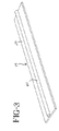
図1には、多層移植片の層のうちの1つを形成する連続したPTFE内側管状本体2が示されている。編組管状本体は、PTFEシート4をマンドレル(図示せず)に巻き付けて長手方向に継目又はシーム6が設けられた管状本体を形成することにより形成される。管の継目(シーム)は、熱を利用し、接着剤を用い、或いはポリマー溶液を用いて接合できる。継目(シーム)を完全に接合してもよく、或いは部分的に接合してもよい。さらに、管は、図1に示すように単一層の巻付け体から成っていてもよく、或いは、PTFEシートを長手方向軸線の回りに多数回巻いて多層内側管を形成したものであってもよい。
【0017】
好ましい実施形態では、管状本体2は、巻きPTFEシートで形成されているが、押出しPTFEの管を用いて本発明の連続内側管状本体を形成してもよい。
【0018】
本明細書で用いる「連続」という用語は、表面がその長手方向距離全体を通じて実質的に中断し又は途切れていない状態で延びる管状構造体を意味している。押出し管の場合、管状構造体は完全に中断し又は途切れていない状態のものである。シートで形成された管の場合、横断方向中断部は存在しない。当該技術分野で知られているように、実質的に中断していない管状構造体は、血管移植片として用いられた場合、強度及び密封特性の向上を示す。
【0019】
図2は、本発明の複合ステント/移植片プロテーゼ11を形成する組立てストリップ8を示している。組立てストリップ8は、平らな移植片ストリップ10と、半径方向に変形可能な支持構造体、例えば、平らなステント12、この実施形態では、波形ワイヤステント14とから成っている。本明細書で用いる「伸長可能」という用語は、ステントを半径方向に伸縮させることができることを示している。ステント12を一時的にストリップに取り付けてもよく、或いは、ステント12を単純にストリップに組み合わせてもよい。複合プロテーゼ11は、組立てストリップを管状内側PTFE本体2に巻き付け、そして移植片ストリップを直接管状移植片本体に固定することによって作られる。図2Aに示すように、好ましくは、ストリップを内側管状本体2に螺旋状に巻き付ける。組立てストリップ8についての1つの好ましい構成例が共通譲受人の米国特許出願(発明の名称:Helically Formed Stent/Graft Assembly )に記載されていて、本願と同日に出願されている。この米国特許出願の開示内容を本明細書の一部を形成するものとしてここに援用する。図2Bに示す別の構成例では、個々の組立てストリップ8′は、管状に継目6′のところで接合されて管状本体2を覆う複数の互いに間隔を置いたステント/移植片カバーを形成している。
【0020】
種々のステント形式及びステント構造を本発明において採用することができる。有用な種々のステントのうちとりわけ、自己拡張性ステント及びバルーンで拡張可能なステントが挙げられるが、これらには限定されない。ステントは、半径方向にも縮むことができ、この意味においては、半径方向に伸長可能又は変形可能であるというべきである。自己拡張性ステントは、ステントを半径方向に拡張させるばねのような挙動をもつステント、又はステント材料の記憶特性により或る特定の温度で或る特定の形態をとるように拡張するステントを含む。ニチノールは、ばね状モードと温度に基づく記憶モードの双方で良好に機能を発揮することができる1つの材料である。当然のことながら、他の材料、例えばステンレス鋼、プラチナ、金、チタン及び他の生体適合性のある金属並びにポリマーステントが考えられる。
【0021】
また、ステントの形態を一群の幾何学的形状から選択することができる。例えば、ワイヤステントをワイヤ中に波形又はジグザグの形を持たせて又はそのようにしないで連続螺旋パターンの状態に締結して半径方向に変形可能なステントを形成することができる。個々のリング又は円形部材を例えばストラット、縫合糸又は溶接により、或いはリングの織編又は係止により互いに連結して管状ステントを形成することができる。本発明に有用な管状ステントとしては、エッチング又は切断加工により管からパターンを得ることにより形成されたステントも挙げられる。かかるステントは、スロット付きステントと呼ばれることが多い。さらに、エッチングによりパターンを材料又は金型に入れ、例えば化学的気相成長法等によりステント材料をパターン中に被着させることによりステントを形成してもよい。
【0022】
図2Aの複合管内プロテーゼ11の製造にあたり、ストリップ8を予め組み立てる必要はない。一製造方法では、内側管状本体2をステント12によって円周方向に包囲する。ステント12を、細長いワイヤ14から形成することができ、かかるワイヤ14を複数の長手方向に間隔を置いたターンをなして螺旋状に巻いて開口した管状の形状にする。ステントは、Rudnick 氏等に付与された米国特許第5,575,816号に記載された形式のものであってもよい。ステント12は、バルーン拡張式又は自己拡張式のものであるのがよい拡張可能な管状部材である。この種のステントは代表的には、経管的に身体に導入され、そして埋め込み部位のところで拡張される。
【0023】
複合管内プロテーゼ11は、ePTFEのストリップをステントに巻き付けることにより完成され、それにより、内側管2及びステント12を円周方向に包囲する非連続PTFE外側管状本体16が形成される。本明細書における「非連続」という用語は、管状構造体が、管状本体の長手方向表面に対して横方向の少なくとも2つの互いに間隔を置いた縁部18,18aを有するのでその長さに沿って実質的に途切れ又は中断していないことを意味している。非連続PTFE外側管状本体16は、ステント12を完全に覆うよう内側管2及びステント12に螺旋状に巻き付けられた平らなPTFEテープで構成されている。
【0024】
外側本体16は、別々のPTFE部品を構成する縁部18を備え、縁部18aは、外側PTFE管状本体16内に開放空間を構成している。外側管16内に図示されたPTFE部材又は部品は、軸方向に巻き付けられたPTFEテープ10の連続して間隔を置いて位置する螺旋ターン16aから成っている。巻回前においては、PTFEテープ10は、実質的に平らな断面を有すると共にテープの幅よりも実質的に長い長手方向長さを有している。
【0025】
次に、図2Bを参照すると、変形例として、個々のステント部分12′を管2に軸方向に巻き付け、ステント部分をストリップ10′で覆い、或いは予め組み立てられたストリップ部分8′を切断してこれらを符号6′のところで継ぎ合わせることによって複合管内プロテーゼを製作してもよい。図2Bの実施形態も又、非連続であって互いに間隔を置いた縁部18を構成し、これら縁部相互間には開放空間が形成されている。
【0026】
図3は、平らな移植片ストリップ20とステント21の組合せから成る別の組立てストリップ構造19を示しており、この実施形態では、ステント21は、実質的に真っ直ぐなワイヤである。組立てストリップ19から複合管内プロテーゼを組み立てる際、ストリップを、図2Aを参照して説明した方法と類似した方法で内側管状本体2の周りに非オーバーラップ形態で螺旋に巻き付けるのがよい。テープ20を内側管状本体2に固定してステントを複合材の内部に封止するのがよい。変形例として、ステントを内側管状部材に巻き付け、移植片ストリップ20をステントの頂部に配置する。また、組立てストリップ19をセグメントの状態に切断し、これらセグメントの各々を管状本体2に円周方向に巻き付け、図2Bを参照して説明した方法と類似した方法で継ぎ合わせてもよいことは注目されるべきである。
【0027】
図4は、これまた非連続外側管を提供する本発明の別の実施形態を示している。この実施形態は、図2及び図2Aと関連して上述したような内側管2及びステント12を採用している。この好ましい実施形態では、複合プロテーゼ22は、個々のPTFEテープの織物又は編物を有する外側管状本体24を備えている。織物構造又は編物構造は、図5に示すような2次元構造のものであってもよく、或いは、図6に示すように3次元形態のものであってもよい。
【0028】
図5は、2次元マトリックスの状態に組み合わされた2つのPTFEテープを示しており、この場合、2つのテープは、非連続管状本体24の別々の部材から成っている。
【0029】
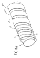
図6は、3つのPTFE孔質テープを3つの方向に互いに編組して構成された3次元編物の拡大図である。かかる編組、編成又は製織構造は、編組、編成又は製織押出し構造内に空間を形成することにより軸方向及び半径方向のコンプライアンスをプロテーゼ22に付与する。
【0030】
密封特性の向上が必要な用途では、図6に示すようなシーラント28を、製織又は編組マトリックス内に散在させて非孔質外側管状本体を形成するのがよい。プロテーゼに用いることができるシーラントとしては、FEP、ポリウレタン及びシリコーンが挙げられる。シーラントとして更に、例えばコラーゲンやヒドロゲルのような生物材料、ポリメチルメタクリレート、ポリアミド及びポリカーボネートが挙げられる。シーラントとしてのエラストマーは可撓性に対する影響の度合は小さいであろう。適当なシーラントを用いることにより、長手方向及び軸方向コンプライアンスをそれほど減少させないで実質的に封止状態の外側管が得られる。
【0031】
上述のように、これまで図示した外側管状本体は、孔質PTFE部材を管状に組み立てて構成された非連続本体を形成している。外側管状本体の非連続構造は、半径方向及び長手方向、又は軸方向のコンプライアンスが向上した複合プロテーゼを提供する。事実、半径方向及び軸方向のコンプライアンスを、管内プロテーゼの使用に適するように使用可能な互いに異なる外側PTFE本体ごとに変えることができる。非連続外側層16は、1本、2本又は3本、或いは4本以上のPTFEテープを上述のPTFE部材から成る軸方向巻付け体、織物、編物又は他の非連続管状本体の状態に巻くことにより形成される。
【0032】
好ましい実施形態では、PTFE部材を形成するPTFEテープは、発泡PTFE(ePTFE)である。「発泡」という用語は、PTFEが特定の方向において、一軸方向、二軸方向又は多軸方向に引き伸ばされることを意味している。本発明のプロテーゼのPTFEテープは代表的には、テープの長手方向に引き伸ばされる。2以上のテープを組み合わせて外側管状本体を形成すると、その結果得られる管状本体は、全体として二軸又は多軸配向性を備える。ePTFEはその引き伸ばし方向において増大した強度を示すので、ePTFEを管状に組み立てた本体は、二軸方向又は多軸方向に引き伸ばされたフィルムの強度が増大するという利点をもたらすが、その非連続表面によりコンプライアンスについても利点が得られる。
【0033】
内側PTFE管状層をステントの開放壁中の空間を通して外側PTFE管状層に結合するのがよい。結合は、接着剤を用いることにより、或いは、接着剤を用いないで層を互いにくっつけることにより行うことができる。接着剤を用いないPTFE層の結合は、例えばプロテーゼの積層法又は焼結法のような方法により行うことができる。さらに、ステントを内側PTFE管状層、外側PTFE管状層又はこれらの両方にくっつけてもよい。同様に、かかる付着は、接着剤を用いても、或いはこれを用いなくても行うことができる。
【0034】
本発明の例示の実施形態を添付の図面を参照して説明したが、本発明はこれらの実施形態そのものには限定されず、当業者であれば、本発明の範囲又は精神から逸脱することなく種々の他の改造例及び設計変更例を想到できることは理解されるべきである。
【図面の簡単な説明】
【図1】
本発明のプロテーゼの内側管状構造体として用いることができる管状構造体の斜視図である。
【図2】
平らな移植片ストリップ及び波形ワイヤステントを有していて、本発明の複合ステント/移植片プロテーゼを形成するための本発明の組立てストリップの斜視図である。
【図2A】
本発明の複合ステント/移植片プロテーゼの部分断面斜視図である。
【図2B】
本発明の別のステント/移植片複合プロテーゼの斜視図である。
【図3】
平らな移植片ストリップ及び実質的に直線状のワイヤステントを有していて、本発明の複合ステント/移植片プロテーゼを形成するための本発明の組立てストリップの斜視図である。
【図3A】
本発明の複合ステント/移植片プロテーゼの一部の斜視図である。
【図4】
本発明の別の実施形態のステント及びPTFE外側管状本体の外面の部分斜視図である。
【図5】
PTFE外側管状本体の別の実施形態の外面の拡大斜視図である。
【図6】
PTFE外側管状本体の別の実施形態の外面の拡大斜視図である。[0001]
(Field of the Invention)
The present invention generally relates to a tubular implantable prosthesis made of porous expanded polytetrafluoroethylene. In particular, the present invention relates to a multilayer composite prosthesis with increased axial and radial compliance.
[0002]
BACKGROUND OF THE INVENTION
An endovascular prosthesis is a medical device commonly known for use in the treatment of diseased blood vessels. Intravascular prostheses are typically used to repair, replace, or correct damaged blood vessels. Arteries or veins can cause disease in a variety of different ways. Thus, the prosthesis can be used to prevent or treat a wide variety of defects, such as vascular stenosis, thrombosis, occlusion or aneurysm.
[0003]
One type of endovascular prosthesis used to repair various vascular disease or lesions is a stent. A stent is a generally longitudinal tubular device made of a biocompatible material useful for patency and supporting the various lumens in the body. For example, stents can be used for the vasculature, urogenital tract, bile ducts, and various other applications in the body. Endovascular stents are becoming widely used to treat stenosis, stenosis, and aneurysms in various blood vessels. These devices are implanted within the vessel for the purpose of opening and / or reinforcing the vascular collapse or partially occluded portion.
[0004]
Stents are generally open at both ends and are generally expandable radially between an unstretched insertion diameter and an expanded implant diameter that is larger than the unstretched insertion diameter. Stents are often flexible in shape so that the stent can be inserted into and adapted to tortuous passages in blood vessels. Stents are typically inserted in a radially compressed state and expanded by the use of a self-expanding mechanism or a balloon catheter.
[0005]
The implant is another type of commonly known endovascular prosthesis that is used for repair and replacement of various body vessels. The graft becomes an artificial lumen through which blood can flow. Implants are tubular devices that can be made of a variety of materials, such materials include woven and non-woven materials. One type of non-woven material that is particularly useful as an implantable endovascular prosthesis is polytetrafluoroethylene (PTFE). PTFE exhibits excellent biocompatibility and low thrombogenicity, and these properties make PTFE particularly useful as a vascular graft material in vascular repair or replacement. For vascular applications, the graft is made from expanded polytetrafluoroethylene (ePTFE) tubing. These tubes have a microporous structure that allows native tissue ingrowth and cell endothelization once implanted in the vasculature. This contributes to the long term healing and patency of the graft. These tubes may be formed from an extruded tube, or a sheet-like film formed into a tube state.
[0006]
A graft made of ePTFE is a fiber composed of interstitial nodes that are interconnected by elongated fibrils or fibrils. The space between the nodal surfaces that are bridged by the fibrils is called the internodal distance (IND). The porosity of the graft is generally measured by IND. With proper tissue ingrowth and cell endothelialization sequence, the graft must have sufficient porosity obtained by expansion. When the term “expanded” is used to describe PTFE, this means that the PTFE has been stretched according to a technique that increases IND and concomitantly increases porosity. The stretching may be uniaxial, biaxial, or multiaxial. Nodes are located spaced apart from one another in the direction of expansion by stretched fibrils. For example, properties such as tensile strength, tear strength and radial (hoop) strength are all dependent on the expansion process. When the film is expanded by stretching the film in two directions that are substantially perpendicular to each other, such as the longitudinal and transverse directions, a biaxially oriented material is formed. A film with fibrils oriented in a multiaxial direction can also be formed by expanding the film in three or more directions. Porous ePTFE grafts have their highest strength in a direction parallel to the orientation of these fibrils. However, increasing strength often reduces flexibility.
[0007]
Although ePTFE has been described above as having desirable biocompatibility, tubes made of ePTFE and films formed in the tube state tend to exhibit axial stiffness and the radial compliance exhibited by them is minimal. Tend to be. Longitudinal compliance is particularly important for endovascular prostheses because the instrument must be delivered through the tortuous passageway of the vessel to the implantation site where it is expanded. Low axial and radial flexibility makes delivery via the tube more difficult.
[0008]
Composite endoprostheses are known in the art. In particular, it is known to combine a stent and a graft to form a composite medical device. Such composite medical devices provide additional support for blood flow through the weakened portion of the blood vessel. For endovascular applications, it is becoming increasingly important to use composite grafts or a combination of stents and grafts. The reason is that such a combination not only allows blood to pass efficiently but also ensures the patency of the implant. However, composite prostheses, especially composite prostheses made of ePTFE, exhibit excellent biocompatibility, but also show reduced axial and radial compliance. Accordingly, it would be desirable to provide an ePTFE composite endovascular prosthesis that exhibits increased axial and radial compliance.
[Summary of the Invention]
The present invention relates to a composite ePTFE vascular prosthesis. The composite has three layers: a radially deformable stent located over the inner tubular ePTFE layer, the discontinuous outer layer and the tubular inner layer and entirely located under the outer layer. Yes.
[0009]
One advantage of the present invention is that it provides an improved composite ePTFE endoprosthesis that exhibits increased axial and circumferential compliance and flexibility and increased tissue ingrowth.
[0010]
Another advantage of the present invention is that it provides an improved stent / graft combination that exhibits increased axial and circumferential compliance and flexibility.
[0011]
Another advantage of the present invention is that it provides increased axial and circumferential compliance and flexibility and increased tissue inward by employing a multiaxial fibril orientation within the discontinuous ePTFE outer tubular body. It is to obtain an improved composite ePTFE endoprosthesis that exhibits a degree of formation.
[0012]
Yet another advantage of the present invention is that it provides an improved method of forming such composites using pre-assembled graft / stent strips.
[0013]
The present invention relates to an implantable composite having a substantially continuous ePTFE tubular inner body in combination with a discontinuous outer ePTFE tubular body formed by a tubular assembled polytetrafluoroethylene strip or polytetrafluoroethylene member. Providing an endovascular prosthesis. A circumferentially extensible support structure is provided between the two PTFE layers. The polytetrafluoroethylene member or strip making up the outer tubular body has a longitudinal length and width, the longitudinal length being greater than the width, and the discontinuous tubular assembly strip is axial and circumferential Compliance is given to the prosthesis.
[0014]
A method of forming an endovascular prosthetic stent / graft with axial and circumferential compliance by combining a discontinuous PTFE tubular outer body with a substantially continuous PTFE tubular inner body disposed thereon is provided. The outer body and the inner body support the stent therebetween. By using braided or woven PTFE in at least the outer layer, axial and circumferential compliance is enhanced and puncture sealing properties are imparted to the prosthesis of the present invention.
[0015]
Detailed Description of Preferred Embodiments
The prosthesis of a preferred embodiment of the present invention is an implantable composite endovascular prosthesis that is particularly suitable for use as an endovascular graft. The composite prosthesis of the present invention has a multilayer graft structure in which a radially deformable stent is interposed between layers. The following description is for the preferred embodiment, but is not intended to limit the invention in any way.
[0016]
FIG. 1 shows a continuous PTFE inner tubular body 2 that forms one of the layers of a multilayer implant. The braided tubular body is formed by winding a PTFE sheet 4 around a mandrel (not shown) to form a tubular body provided with a seam or seam 6 in the longitudinal direction. The seam of the tube can be joined using heat, using an adhesive, or using a polymer solution. The seam may be fully joined or partially joined. Further, the tube may be formed of a single layer wound body as shown in FIG. 1, or a PTFE sheet may be wound many times around the longitudinal axis to form a multilayer inner tube. Good.
[0017]
In a preferred embodiment, the tubular body 2 is formed of a wound PTFE sheet, but extruded PTFE tubing may be used to form the continuous inner tubular body of the present invention.
[0018]
As used herein, the term “continuous” refers to a tubular structure that extends with the surface substantially uninterrupted or uninterrupted throughout its longitudinal distance. In the case of extruded tubes, the tubular structure is in a state of complete interruption or uninterrupted. In the case of a tube formed from a sheet, there are no transverse interruptions. As is known in the art, a substantially uninterrupted tubular structure exhibits improved strength and sealing properties when used as a vascular graft.
[0019]
FIG. 2 shows the assembly strip 8 forming the composite stent / graft prosthesis 11 of the present invention. The assembly strip 8 consists of a
[0020]
Various stent types and stent structures can be employed in the present invention. Among the various useful stents include, but are not limited to, self-expandable stents and balloon expandable stents. A stent can also shrink in the radial direction, and in this sense it should be radially extensible or deformable. Self-expanding stents include stents that behave like a spring that causes the stent to expand radially, or that expand to take a certain form at a certain temperature due to the memory properties of the stent material. Nitinol is one material that can perform well in both spring-like mode and temperature-based memory mode. Of course, other materials are contemplated such as stainless steel, platinum, gold, titanium and other biocompatible metals and polymer stents.
[0021]
Also, the stent configuration can be selected from a group of geometric shapes. For example, a wire stent can be fastened in a continuous helical pattern with or without a corrugation or zigzag shape in the wire to form a radially deformable stent. Individual rings or circular members can be joined together to form a tubular stent, for example by struts, sutures or welds, or by knitting or locking the rings. Tubular stents useful in the present invention also include stents formed by obtaining a pattern from a tube by etching or cutting. Such stents are often referred to as slotted stents. Further, the stent may be formed by putting the pattern into a material or a mold by etching and depositing the stent material in the pattern by, for example, chemical vapor deposition.
[0022]
In manufacturing the composite in-tube prosthesis 11 of FIG. 2A, the strip 8 need not be pre-assembled. In one manufacturing method, the inner tubular body 2 is circumferentially surrounded by the
[0023]
The composite endovascular prosthesis 11 is completed by wrapping a strip of ePTFE around the stent, thereby forming a discontinuous PTFE outer tubular body 16 that circumferentially surrounds the inner tube 2 and the
[0024]
The outer body 16 includes an edge 18 that constitutes a separate PTFE component, and the edge 18 a defines an open space within the outer PTFE tubular body 16. The PTFE member or part shown in the outer tube 16 comprises a series of spaced apart helical turns 16a of axially wound
[0025]
Referring now to FIG. 2B, as an alternative, individual stent portions 12 'are wound axially around the tube 2 and the stent portions are covered with strips 10' or pre-assembled strip portions 8 'are cut. A composite in-tube prosthesis may be fabricated by splicing these at 6 '. The embodiment of FIG. 2B also constitutes edges 18 that are non-continuous and spaced from each other, with an open space formed between the edges.
[0026]
FIG. 3 shows another assembled
[0027]
FIG. 4 shows another embodiment of the invention that also provides a discontinuous outer tube. This embodiment employs the inner tube 2 and
[0028]
FIG. 5 shows two PTFE tapes combined in a two-dimensional matrix, where the two tapes consist of separate members of a non-continuous
[0029]
FIG. 6 is an enlarged view of a three-dimensional knitted fabric formed by braiding three PTFE porous tapes in three directions. Such braided, knitted or woven structures impart axial and radial compliance to the prosthesis 22 by creating a space within the braided, knitted or woven extruded structure.
[0030]
For applications that require improved sealing properties, sealant 28 as shown in FIG. 6 may be interspersed within a woven or braided matrix to form a non-porous outer tubular body. Sealants that can be used in the prosthesis include FEP, polyurethane, and silicone. Further examples of the sealant include biological materials such as collagen and hydrogel, polymethyl methacrylate, polyamide and polycarbonate. Elastomers as sealants will have a small impact on flexibility. By using a suitable sealant, a substantially sealed outer tube is obtained without significantly reducing longitudinal and axial compliance.
[0031]
As described above, the outer tubular body illustrated so far forms a discontinuous body constructed by assembling a porous PTFE member into a tubular shape. The discontinuous structure of the outer tubular body provides a composite prosthesis with improved radial and longitudinal or axial compliance. In fact, radial and axial compliance can vary for different outer PTFE bodies that can be used to suit the use of an endovascular prosthesis. The non-continuous outer layer 16 winds one, two, three, or four or more PTFE tapes in the form of an axially wound body, woven fabric, knitted fabric or other non-continuous tubular body comprised of the PTFE members described above. Is formed.
[0032]
In a preferred embodiment, the PTFE tape forming the PTFE member is expanded PTFE (ePTFE). The term “foaming” means that PTFE is stretched in a particular direction, uniaxial, biaxial or multiaxial. The PTFE tape of the prosthesis of the present invention is typically stretched in the longitudinal direction of the tape. When two or more tapes are combined to form the outer tubular body, the resulting tubular body generally has biaxial or multiaxial orientation. Since ePTFE exhibits increased strength in its stretch direction, a body assembled with ePTFE in a tubular shape has the advantage of increasing the strength of a biaxially or multiaxially stretched film, but due to its discontinuous surface. There are also benefits to compliance.
[0033]
The inner PTFE tubular layer may be bonded to the outer PTFE tubular layer through a space in the open wall of the stent. Bonding can be done by using an adhesive or by sticking the layers together without using an adhesive. Bonding of the PTFE layer without using an adhesive can be performed by a method such as a prosthesis lamination method or a sintering method. Further, the stent may be attached to the inner PTFE tubular layer, the outer PTFE tubular layer, or both. Similarly, such attachment can be performed with or without an adhesive.
[0034]
Although exemplary embodiments of the present invention have been described with reference to the accompanying drawings, the present invention is not limited to these embodiments themselves, and those skilled in the art will not depart from the scope or spirit of the present invention. It should be understood that various other modifications and design changes can be envisaged.
[Brief description of the drawings]
[Figure 1]
It is a perspective view of the tubular structure which can be used as an inner tubular structure of the prosthesis of the present invention.
[Figure 2]
1 is a perspective view of an inventive assembly strip for forming a composite stent / graft prosthesis of the present invention having a flat graft strip and a corrugated wire stent. FIG.
FIG. 2A
1 is a partial cross-sectional perspective view of a composite stent / graft prosthesis of the present invention. FIG.
FIG. 2B
FIG. 6 is a perspective view of another stent / graft composite prosthesis of the present invention.
[Fig. 3]
1 is a perspective view of an inventive assembly strip for forming a composite stent / graft prosthesis of the present invention having a flat graft strip and a substantially straight wire stent. FIG.
FIG. 3A
1 is a perspective view of a portion of a composite stent / graft prosthesis of the present invention. FIG.
[Fig. 4]
FIG. 6 is a partial perspective view of the outer surface of a stent and PTFE outer tubular body of another embodiment of the present invention.
[Figure 5]
FIG. 6 is an enlarged perspective view of the outer surface of another embodiment of a PTFE outer tubular body.
[Fig. 6]
FIG. 6 is an enlarged perspective view of the outer surface of another embodiment of a PTFE outer tubular body.
Claims (20)
実質的に連続したポリテトラフルオロエチレンの内側管状本体と、
長手方向に非連続の外側管状本体と、
内側管状本体と外側管状本体との間に配置された円周方向に伸長可能な支持構造体とを含み、前記外側管状本体は、長手方向長さ及び幅を備えたポリテトラフルオロエチレン部材で形成され、前記長手方向長さは、前記幅よりも大きく、前記ポリテトラフルオロエチレン部材は、伸長可能な支持構造体を完全に覆い、それにより、軸方向及び円周方向コンプライアンスが前記プロテーゼに与えられていることを特徴とする複合管内プロテーゼ。An implantable composite endoprosthesis,
A substantially continuous polytetrafluoroethylene inner tubular body;
A longitudinally non-continuous outer tubular body;
A circumferentially extendable support structure disposed between the inner tubular body and the outer tubular body, the outer tubular body formed of a polytetrafluoroethylene member having a longitudinal length and width The longitudinal length is greater than the width, and the polytetrafluoroethylene member completely covers the extensible support structure, thereby providing axial and circumferential compliance to the prosthesis. A composite endoprosthesis characterized by
(a)連続ePTFE内側管状本体を準備する段階と、
(b)ステントを前記連続ePTFE管状内側本体に非オーバーラップ関係で巻き付ける段階と、
(c)ePTFEストリップを管状内側本体及びステントに巻き付けてステントを完全に覆う段階と、
を含むことを特徴とする方法。A method of manufacturing an implantable endovascular stent / graft composite prosthesis comprising:
(A) providing a continuous ePTFE inner tubular body;
(B) winding the stent around the continuous ePTFE tubular inner body in a non-overlapping relationship;
(C) wrapping the ePTFE strip around the tubular inner body and stent to completely cover the stent;
A method comprising the steps of:
(a)幅よりも大きな長さを有するePTFEストリップを準備する段階と、 (b)巻いていない状態のスリップを準備する段階と、
(c)ステントをストリップと組み合わせてステント側及びePTFEストリップ側を備えた組立てストリップを形成する段階と、
(d)連続管状内側本体を準備する段階と、
(e)組立てストリップを内側本体に非オーバーラップ関係をなして巻き付けてステントを完全に覆うようにする段階と、
を含むことを特徴とする方法。A method of manufacturing an implantable endovascular stent / graft prosthesis comprising:
(A) providing an ePTFE strip having a length greater than the width; (b) preparing an unrolled slip;
(C) combining the stent with the strip to form an assembled strip with a stent side and an ePTFE strip side;
(D) providing a continuous tubular inner body;
(E) wrapping the assembly strip around the inner body in a non-overlapping relationship to completely cover the stent;
A method comprising the steps of:
Applications Claiming Priority (2)
| Application Number | Priority Date | Filing Date | Title |
|---|---|---|---|
| US09/347,218 US6652570B2 (en) | 1999-07-02 | 1999-07-02 | Composite vascular graft |
| PCT/US2000/017448 WO2001001887A1 (en) | 1999-07-02 | 2000-06-23 | Improved composite vascular graft |
Publications (1)
| Publication Number | Publication Date |
|---|---|
| JP2006512099A true JP2006512099A (en) | 2006-04-13 |
Family
ID=23362798
Family Applications (2)
| Application Number | Title | Priority Date | Filing Date |
|---|---|---|---|
| JP2001507391A Pending JP2003503151A (en) | 1999-07-02 | 2000-06-23 | Composite vascular graft |
| JP2001507391D Pending JP2006512099A (en) | 1999-07-02 | 2000-06-23 | Composite vascular graft |
Family Applications Before (1)
| Application Number | Title | Priority Date | Filing Date |
|---|---|---|---|
| JP2001507391A Pending JP2003503151A (en) | 1999-07-02 | 2000-06-23 | Composite vascular graft |
Country Status (8)
| Country | Link |
|---|---|
| US (2) | US6652570B2 (en) |
| EP (1) | EP1194080B1 (en) |
| JP (2) | JP2003503151A (en) |
| AT (1) | ATE369089T1 (en) |
| CA (1) | CA2377961C (en) |
| DE (1) | DE60035877T2 (en) |
| ES (1) | ES2290044T3 (en) |
| WO (1) | WO2001001887A1 (en) |
Cited By (6)
| Publication number | Priority date | Publication date | Assignee | Title |
|---|---|---|---|---|
| JP2010530786A (en) * | 2007-06-22 | 2010-09-16 | シー・アール・バード・インコーポレーテッド | Helical and segmented stent grafts |
| JP2013507194A (en) * | 2009-10-09 | 2013-03-04 | ゴア エンタープライズ ホールディングス,インコーポレイティド | Branch access for highly conformable bifurcated medical devices |
| US9427343B2 (en) | 2007-06-22 | 2016-08-30 | David L. Bogert | Locked segments pushable stent-graft |
| JP2017060851A (en) * | 2012-04-06 | 2017-03-30 | ボストン サイエンティフィック サイムド,インコーポレイテッドBoston Scientific Scimed,Inc. | Endoprosthesis |
| JP2017509439A (en) * | 2014-04-04 | 2017-04-06 | ダブリュ.エル.ゴア アンド アソシエイツ,インコーポレイティドW.L. Gore & Associates, Incorporated | Bifurcated graft device |
| JP2018530359A (en) * | 2015-07-27 | 2018-10-18 | テウン メディカル カンパニー リミテッド | Stent with improved anti-slip function |
Families Citing this family (67)
| Publication number | Priority date | Publication date | Assignee | Title |
|---|---|---|---|---|
| US6395019B2 (en) | 1998-02-09 | 2002-05-28 | Trivascular, Inc. | Endovascular graft |
| US6945991B1 (en) * | 2000-11-28 | 2005-09-20 | Boston Scientific/Scimed Life Systems, Inc. | Composite tubular prostheses |
| US7147661B2 (en) | 2001-12-20 | 2006-12-12 | Boston Scientific Santa Rosa Corp. | Radially expandable stent |
| US7125464B2 (en) | 2001-12-20 | 2006-10-24 | Boston Scientific Santa Rosa Corp. | Method for manufacturing an endovascular graft section |
| US7090693B1 (en) | 2001-12-20 | 2006-08-15 | Boston Scientific Santa Rosa Corp. | Endovascular graft joint and method for manufacture |
| US6776604B1 (en) | 2001-12-20 | 2004-08-17 | Trivascular, Inc. | Method and apparatus for shape forming endovascular graft material |
| US9539121B2 (en) * | 2002-02-07 | 2017-01-10 | Dsm Ip Assets B.V. | Apparatus and methods for conduits and materials |
| US7166124B2 (en) * | 2002-03-21 | 2007-01-23 | Providence Health System - Oregon | Method for manufacturing sutureless bioprosthetic stent |
| EP1374799A1 (en) | 2002-06-18 | 2004-01-02 | F.R.I.D. R&D Benelux Sprl | Hemodynamic luminal endoprosthesis |
| US8088158B2 (en) * | 2002-12-20 | 2012-01-03 | Boston Scientific Scimed, Inc. | Radiopaque ePTFE medical devices |
| US7803178B2 (en) | 2004-01-30 | 2010-09-28 | Trivascular, Inc. | Inflatable porous implants and methods for drug delivery |
| US20050223440A1 (en) * | 2004-03-31 | 2005-10-06 | Council Of Scientific And Industrial Research | Tissue culture process for producing cotton plants |
| US8034096B2 (en) | 2004-03-31 | 2011-10-11 | Cook Medical Technologies Llc | Stent-graft with graft to graft attachment |
| US8377110B2 (en) * | 2004-04-08 | 2013-02-19 | Endologix, Inc. | Endolumenal vascular prosthesis with neointima inhibiting polymeric sleeve |
| CN100352406C (en) * | 2004-08-17 | 2007-12-05 | 微创医疗器械(上海)有限公司 | Combined membrane-covered stent capable of being bent in any direction |
| US20060058867A1 (en) * | 2004-09-15 | 2006-03-16 | Thistle Robert C | Elastomeric radiopaque adhesive composite and prosthesis |
| US20060142852A1 (en) * | 2004-12-29 | 2006-06-29 | Boston Scientific Scimed, Inc. | Low profile, durable, reinforced ePTFE composite graft |
| US7318838B2 (en) * | 2004-12-31 | 2008-01-15 | Boston Scientific Scimed, Inc. | Smart textile vascular graft |
| US8652193B2 (en) * | 2005-05-09 | 2014-02-18 | Angiomed Gmbh & Co. Medizintechnik Kg | Implant delivery device |
| GB0517085D0 (en) * | 2005-08-19 | 2005-09-28 | Angiomed Ag | Polymer prosthesis |
| US7655035B2 (en) * | 2005-10-05 | 2010-02-02 | Boston Scientific Scimed, Inc. | Variable lamination of vascular graft |
| US8784477B2 (en) * | 2011-01-05 | 2014-07-22 | Abbott Cardiovascular Systems Inc. | Stent graft with two layer ePTFE layer system with high plasticity and high rigidity |
| US20070208409A1 (en) * | 2006-03-01 | 2007-09-06 | Boston Scientific Scimed, Inc. | Flexible stent-graft devices and methods of producing the same |
| US20070225799A1 (en) * | 2006-03-24 | 2007-09-27 | Medtronic Vascular, Inc. | Stent, intraluminal stent delivery system, and method of treating a vascular condition |
| WO2008027188A2 (en) * | 2006-08-29 | 2008-03-06 | C. R. Bard, Inc. | Helical high fatigue stent-graft |
| WO2008033678A2 (en) * | 2006-09-14 | 2008-03-20 | C. R. Bard, Inc. | Compressed inner covering hinged segmented stent-graft |
| US20100016946A1 (en) * | 2006-09-18 | 2010-01-21 | C.R. Bard, Inc | Single layer eptfe and discrete bioresorbable rings |
| US7785363B2 (en) * | 2007-08-15 | 2010-08-31 | Boston Scientific Scimed, Inc. | Skewed nodal-fibril ePTFE structure |
| US8906081B2 (en) | 2007-09-13 | 2014-12-09 | W. L. Gore & Associates, Inc. | Stented vascular graft |
| US8226701B2 (en) | 2007-09-26 | 2012-07-24 | Trivascular, Inc. | Stent and delivery system for deployment thereof |
| US8663309B2 (en) | 2007-09-26 | 2014-03-04 | Trivascular, Inc. | Asymmetric stent apparatus and method |
| US8066755B2 (en) | 2007-09-26 | 2011-11-29 | Trivascular, Inc. | System and method of pivoted stent deployment |
| JP2010540190A (en) | 2007-10-04 | 2010-12-24 | トリバスキュラー・インコーポレイテッド | Modular vascular graft for low profile transdermal delivery |
| US8083789B2 (en) | 2007-11-16 | 2011-12-27 | Trivascular, Inc. | Securement assembly and method for expandable endovascular device |
| US8328861B2 (en) | 2007-11-16 | 2012-12-11 | Trivascular, Inc. | Delivery system and method for bifurcated graft |
| US20090287145A1 (en) * | 2008-05-15 | 2009-11-19 | Altura Interventional, Inc. | Devices and methods for treatment of abdominal aortic aneurysms |
| US20100305686A1 (en) * | 2008-05-15 | 2010-12-02 | Cragg Andrew H | Low-profile modular abdominal aortic aneurysm graft |
| US20130268062A1 (en) | 2012-04-05 | 2013-10-10 | Zeus Industrial Products, Inc. | Composite prosthetic devices |
| PL2384375T3 (en) | 2009-01-16 | 2017-12-29 | Zeus Industrial Products, Inc. | Electrospinning of ptfe with high viscosity materials |
| JP5456892B2 (en) | 2009-08-07 | 2014-04-02 | ゼウス インダストリアル プロダクツ インコーポレイテッド | Multilayer composite |
| US20110130825A1 (en) * | 2009-12-01 | 2011-06-02 | Altura Medical, Inc. | Modular endograft devices and associated systems and methods |
| EP2519189B1 (en) | 2009-12-28 | 2014-05-07 | Cook Medical Technologies LLC | Endoluminal device with kink-resistant regions |
| WO2012040240A1 (en) | 2010-09-20 | 2012-03-29 | Altura Medical, Inc. | Stent graft delivery systems and associated methods |
| US8409224B2 (en) | 2010-10-04 | 2013-04-02 | Edgar L Shriver | Suturing graft tubes to lumen walls percutaneously |
| RU2581871C2 (en) | 2011-01-28 | 2016-04-20 | Мерит Медикал Системз, Инк. | Electrospun ptfe coated stent and method of use |
| CN102198025A (en) * | 2011-05-04 | 2011-09-28 | 迟立群 | Stent graft |
| WO2013109528A1 (en) * | 2012-01-16 | 2013-07-25 | Merit Medical Systems, Inc. | Rotational spun material covered medical appliances and methods of manufacture |
| US8992595B2 (en) | 2012-04-04 | 2015-03-31 | Trivascular, Inc. | Durable stent graft with tapered struts and stable delivery methods and devices |
| US9498363B2 (en) | 2012-04-06 | 2016-11-22 | Trivascular, Inc. | Delivery catheter for endovascular device |
| EP2844903A4 (en) * | 2012-05-03 | 2015-12-23 | Titeflex Commercial Inc | Tubes and methods of production and use thereof |
| EP2882381B1 (en) | 2012-08-10 | 2018-12-26 | Lombard Medical Limited | Stent delivery system |
| US11541154B2 (en) * | 2012-09-19 | 2023-01-03 | Merit Medical Systems, Inc. | Electrospun material covered medical appliances and methods of manufacture |
| US9198999B2 (en) | 2012-09-21 | 2015-12-01 | Merit Medical Systems, Inc. | Drug-eluting rotational spun coatings and methods of use |
| US8709059B1 (en) | 2012-12-10 | 2014-04-29 | Edgar L. Shriver | Suturing an expanding, contracting graft tube in artery segment previously occluded |
| US10799617B2 (en) | 2013-03-13 | 2020-10-13 | Merit Medical Systems, Inc. | Serially deposited fiber materials and associated devices and methods |
| WO2014159399A1 (en) | 2013-03-13 | 2014-10-02 | Merit Medical Systems, Inc. | Methods, systems, and apparatuses for manufacturing rotational spun appliances |
| US20140277381A1 (en) * | 2013-03-14 | 2014-09-18 | W. L. Gore & Associates, Inc. | Methods and apparatus for assembling stent-grafts |
| US9737426B2 (en) | 2013-03-15 | 2017-08-22 | Altura Medical, Inc. | Endograft device delivery systems and associated methods |
| KR101557010B1 (en) * | 2014-07-11 | 2015-10-02 | 주식회사 비씨엠 | A Covered Stents and the making Methods for a Covered Stent |
| EP3244843B1 (en) | 2015-01-12 | 2022-08-24 | Microvention, Inc. | Stent |
| JP6777642B2 (en) | 2015-02-26 | 2020-10-28 | メリット・メディカル・システムズ・インコーポレイテッドMerit Medical Systems,Inc. | Layered medical devices and methods |
| AU2016226128B2 (en) | 2015-03-03 | 2020-10-08 | Titeflex Commercial Inc. | Composite hose assembly |
| CN109419568B (en) * | 2017-08-28 | 2023-09-19 | 先健科技(深圳)有限公司 | Tectorial membrane support |
| CA3101217C (en) | 2018-06-11 | 2023-03-28 | Boston Scientific Scimed, Inc. | Sphincterotomes and methods for using sphincterotomes |
| WO2021016055A1 (en) * | 2019-07-19 | 2021-01-28 | The Secant Group, Llc | Poly(glycerol sebacate)-infused hollow lumen composite graft |
| US11944557B2 (en) | 2020-08-31 | 2024-04-02 | Boston Scientific Scimed, Inc. | Self expanding stent with covering |
| WO2024009265A1 (en) | 2022-07-08 | 2024-01-11 | Ecole Polytechnique Federale De Lausanne (Epfl) | Compliant vascular grafts and methods of use |
Family Cites Families (41)
| Publication number | Priority date | Publication date | Assignee | Title |
|---|---|---|---|---|
| JPS58136122A (en) * | 1982-02-08 | 1983-08-13 | Marantz Japan Inc | Low frequency sound emphasis circuit for audio equipment |
| US5669936A (en) | 1983-12-09 | 1997-09-23 | Endovascular Technologies, Inc. | Endovascular grafting system and method for use therewith |
| US4925710A (en) | 1988-03-31 | 1990-05-15 | Buck Thomas F | Ultrathin-wall fluoropolymer tube with removable fluoropolymer core |
| JPH03280949A (en) * | 1990-03-29 | 1991-12-11 | Jinkou Ketsukan Gijutsu Kenkyu Center:Kk | Multilayer artificial blood vessel |
| US5123917A (en) | 1990-04-27 | 1992-06-23 | Lee Peter Y | Expandable intraluminal vascular graft |
| DE69118083T2 (en) | 1990-10-09 | 1996-08-22 | Cook Inc | Percutaneous stent assembly |
| JPH0515585A (en) * | 1991-07-12 | 1993-01-26 | Kobe Steel Ltd | Tube for heart-lung machine |
| US5395349A (en) | 1991-12-13 | 1995-03-07 | Endovascular Technologies, Inc. | Dual valve reinforced sheath and method |
| JPH07507014A (en) * | 1992-03-13 | 1995-08-03 | アトリウム メディカル コーポレイション | Expanded polytetrafluoroethylene products and fabrication with controlled porosity |
| US5507771A (en) | 1992-06-15 | 1996-04-16 | Cook Incorporated | Stent assembly |
| US5716395A (en) | 1992-12-11 | 1998-02-10 | W.L. Gore & Associates, Inc. | Prosthetic vascular graft |
| US5466509A (en) | 1993-01-15 | 1995-11-14 | Impra, Inc. | Textured, porous, expanded PTFE |
| CA2169549C (en) | 1993-08-18 | 2000-07-11 | James D. Lewis | A tubular intraluminal graft |
| US6027779A (en) | 1993-08-18 | 2000-02-22 | W. L. Gore & Associates, Inc. | Thin-wall polytetrafluoroethylene tube |
| US5735892A (en) | 1993-08-18 | 1998-04-07 | W. L. Gore & Associates, Inc. | Intraluminal stent graft |
| AU6943794A (en) | 1993-08-18 | 1995-03-14 | W.L. Gore & Associates, Inc. | A thin-wall, seamless, porous polytetrafluoroethylene tube |
| US5389106A (en) | 1993-10-29 | 1995-02-14 | Numed, Inc. | Impermeable expandable intravascular stent |
| EP0792627B2 (en) | 1994-06-08 | 2003-10-29 | Cardiovascular Concepts, Inc. | System for forming a bifurcated graft |
| US5556426A (en) * | 1994-08-02 | 1996-09-17 | Meadox Medicals, Inc. | PTFE implantable tubular prostheses with external coil support |
| US5575816A (en) * | 1994-08-12 | 1996-11-19 | Meadox Medicals, Inc. | High strength and high density intraluminal wire stent |
| EP0810845A2 (en) | 1995-02-22 | 1997-12-10 | Menlo Care Inc. | Covered expanding mesh stent |
| US6264684B1 (en) * | 1995-03-10 | 2001-07-24 | Impra, Inc., A Subsidiary Of C.R. Bard, Inc. | Helically supported graft |
| ES2151082T3 (en) | 1995-03-10 | 2000-12-16 | Impra Inc | ENDOLUMINAL ENCAPSULATED SUPPORT AND PROCEDURES FOR ITS MANUFACTURE AND ENDOLUMINAL PLACEMENT. |
| US6579314B1 (en) | 1995-03-10 | 2003-06-17 | C.R. Bard, Inc. | Covered stent with encapsulated ends |
| US6124523A (en) | 1995-03-10 | 2000-09-26 | Impra, Inc. | Encapsulated stent |
| US5641373A (en) | 1995-04-17 | 1997-06-24 | Baxter International Inc. | Method of manufacturing a radially-enlargeable PTFE tape-reinforced vascular graft |
| WO1996040001A1 (en) * | 1995-06-07 | 1996-12-19 | Baxter International Inc. | Externally supported tape reinforced vascular graft |
| DE19531659C2 (en) | 1995-08-29 | 1998-07-02 | Ernst Peter Prof Dr M Strecker | Stent |
| US5562697A (en) | 1995-09-18 | 1996-10-08 | William Cook, Europe A/S | Self-expanding stent assembly and methods for the manufacture thereof |
| US5824037A (en) | 1995-10-03 | 1998-10-20 | Medtronic, Inc. | Modular intraluminal prostheses construction and methods |
| US5591195A (en) | 1995-10-30 | 1997-01-07 | Taheri; Syde | Apparatus and method for engrafting a blood vessel |
| US6042605A (en) | 1995-12-14 | 2000-03-28 | Gore Enterprose Holdings, Inc. | Kink resistant stent-graft |
| CA2246157C (en) * | 1995-12-14 | 2007-02-20 | Gore Enterprise Holdings, Inc. | Kink resistant stent-graft |
| US5800512A (en) * | 1996-01-22 | 1998-09-01 | Meadox Medicals, Inc. | PTFE vascular graft |
| US5607478A (en) * | 1996-03-14 | 1997-03-04 | Meadox Medicals Inc. | Yarn wrapped PTFE tubular prosthesis |
| US5928279A (en) * | 1996-07-03 | 1999-07-27 | Baxter International Inc. | Stented, radially expandable, tubular PTFE grafts |
| US5897587A (en) | 1996-12-03 | 1999-04-27 | Atrium Medical Corporation | Multi-stage prosthesis |
| US6551350B1 (en) | 1996-12-23 | 2003-04-22 | Gore Enterprise Holdings, Inc. | Kink resistant bifurcated prosthesis |
| US6352561B1 (en) | 1996-12-23 | 2002-03-05 | W. L. Gore & Associates | Implant deployment apparatus |
| US6558414B2 (en) | 1999-02-02 | 2003-05-06 | Impra, Inc. | Partial encapsulation of stents using strips and bands |
| US6398803B1 (en) | 1999-02-02 | 2002-06-04 | Impra, Inc., A Subsidiary Of C.R. Bard, Inc. | Partial encapsulation of stents |
-
1999
- 1999-07-02 US US09/347,218 patent/US6652570B2/en not_active Expired - Lifetime
-
2000
- 2000-06-23 ES ES00943142T patent/ES2290044T3/en not_active Expired - Lifetime
- 2000-06-23 DE DE60035877T patent/DE60035877T2/en not_active Expired - Lifetime
- 2000-06-23 CA CA002377961A patent/CA2377961C/en not_active Expired - Fee Related
- 2000-06-23 WO PCT/US2000/017448 patent/WO2001001887A1/en active IP Right Grant
- 2000-06-23 JP JP2001507391A patent/JP2003503151A/en active Pending
- 2000-06-23 EP EP00943142A patent/EP1194080B1/en not_active Expired - Lifetime
- 2000-06-23 AT AT00943142T patent/ATE369089T1/en not_active IP Right Cessation
- 2000-06-23 JP JP2001507391D patent/JP2006512099A/en active Pending
-
2003
- 2003-08-19 US US10/643,527 patent/US20040054397A1/en not_active Abandoned
Cited By (9)
| Publication number | Priority date | Publication date | Assignee | Title |
|---|---|---|---|---|
| JP2010530786A (en) * | 2007-06-22 | 2010-09-16 | シー・アール・バード・インコーポレーテッド | Helical and segmented stent grafts |
| US9427343B2 (en) | 2007-06-22 | 2016-08-30 | David L. Bogert | Locked segments pushable stent-graft |
| US10449067B2 (en) | 2007-06-22 | 2019-10-22 | C. R. Bard, Inc. | Locked segments pushable stent-graft |
| JP2013507194A (en) * | 2009-10-09 | 2013-03-04 | ゴア エンタープライズ ホールディングス,インコーポレイティド | Branch access for highly conformable bifurcated medical devices |
| US9827118B2 (en) | 2009-10-09 | 2017-11-28 | W. L. Gore & Associates, Inc. | Bifurcated highly conformable medical device branch access |
| JP2017060851A (en) * | 2012-04-06 | 2017-03-30 | ボストン サイエンティフィック サイムド,インコーポレイテッドBoston Scientific Scimed,Inc. | Endoprosthesis |
| US10441406B2 (en) | 2012-04-06 | 2019-10-15 | Boston Scientific Scimed, Inc. | Anti-migration micropatterned stent coating |
| JP2017509439A (en) * | 2014-04-04 | 2017-04-06 | ダブリュ.エル.ゴア アンド アソシエイツ,インコーポレイティドW.L. Gore & Associates, Incorporated | Bifurcated graft device |
| JP2018530359A (en) * | 2015-07-27 | 2018-10-18 | テウン メディカル カンパニー リミテッド | Stent with improved anti-slip function |
Also Published As
| Publication number | Publication date |
|---|---|
| US6652570B2 (en) | 2003-11-25 |
| US20010023370A1 (en) | 2001-09-20 |
| WO2001001887A1 (en) | 2001-01-11 |
| DE60035877D1 (en) | 2007-09-20 |
| WO2001001887A9 (en) | 2001-04-26 |
| EP1194080B1 (en) | 2007-08-08 |
| JP2003503151A (en) | 2003-01-28 |
| ES2290044T3 (en) | 2008-02-16 |
| DE60035877T2 (en) | 2008-04-24 |
| CA2377961C (en) | 2008-12-30 |
| ATE369089T1 (en) | 2007-08-15 |
| US20040054397A1 (en) | 2004-03-18 |
| CA2377961A1 (en) | 2001-01-11 |
| EP1194080A1 (en) | 2002-04-10 |
Similar Documents
| Publication | Publication Date | Title |
|---|---|---|
| JP2006512099A (en) | Composite vascular graft | |
| US6929709B2 (en) | Helically formed stent/graft assembly | |
| EP1207815B1 (en) | Tubular stent-graft composite device and method of manufacture | |
| US20010018609A1 (en) | Seamless braided or spun stent cover | |
| US6004348A (en) | Endoluminal encapsulated stent and methods of manufacture and endoluminal delivery | |
| US5749880A (en) | Endoluminal encapsulated stent and methods of manufacture and endoluminal delivery | |
| US6312458B1 (en) | Tubular structure/stent/stent securement member | |
| US6143022A (en) | Stent-graft assembly with dual configuration graft component and method of manufacture | |
| JP4739533B2 (en) | Increased flexibility stent-graft | |
| CA2429619C (en) | Composite tubular prostheses | |
| EP1767169B1 (en) | Tubular stent-graft composite device and method of manufacture |
Legal Events
| Date | Code | Title | Description |
|---|---|---|---|
| A02 | Decision of refusal |
Free format text: JAPANESE INTERMEDIATE CODE: A02 Effective date: 20110310 |