JP2006507982A - Control panel and control panel manufacturing method - Google Patents
Control panel and control panel manufacturing method Download PDFInfo
- Publication number
- JP2006507982A JP2006507982A JP2004556248A JP2004556248A JP2006507982A JP 2006507982 A JP2006507982 A JP 2006507982A JP 2004556248 A JP2004556248 A JP 2004556248A JP 2004556248 A JP2004556248 A JP 2004556248A JP 2006507982 A JP2006507982 A JP 2006507982A
- Authority
- JP
- Japan
- Prior art keywords
- control panel
- linear element
- mold
- linear
- plastic
- Prior art date
- Legal status (The legal status is an assumption and is not a legal conclusion. Google has not performed a legal analysis and makes no representation as to the accuracy of the status listed.)
- Pending
Links
Images


Classifications
-
- B—PERFORMING OPERATIONS; TRANSPORTING
- B29—WORKING OF PLASTICS; WORKING OF SUBSTANCES IN A PLASTIC STATE IN GENERAL
- B29C—SHAPING OR JOINING OF PLASTICS; SHAPING OF MATERIAL IN A PLASTIC STATE, NOT OTHERWISE PROVIDED FOR; AFTER-TREATMENT OF THE SHAPED PRODUCTS, e.g. REPAIRING
- B29C43/00—Compression moulding, i.e. applying external pressure to flow the moulding material; Apparatus therefor
- B29C43/003—Compression moulding, i.e. applying external pressure to flow the moulding material; Apparatus therefor characterised by the choice of material
-
- B—PERFORMING OPERATIONS; TRANSPORTING
- B29—WORKING OF PLASTICS; WORKING OF SUBSTANCES IN A PLASTIC STATE IN GENERAL
- B29C—SHAPING OR JOINING OF PLASTICS; SHAPING OF MATERIAL IN A PLASTIC STATE, NOT OTHERWISE PROVIDED FOR; AFTER-TREATMENT OF THE SHAPED PRODUCTS, e.g. REPAIRING
- B29C45/00—Injection moulding, i.e. forcing the required volume of moulding material through a nozzle into a closed mould; Apparatus therefor
- B29C45/14—Injection moulding, i.e. forcing the required volume of moulding material through a nozzle into a closed mould; Apparatus therefor incorporating preformed parts or layers, e.g. injection moulding around inserts or for coating articles
- B29C45/14631—Coating reinforcements
-
- B—PERFORMING OPERATIONS; TRANSPORTING
- B29—WORKING OF PLASTICS; WORKING OF SUBSTANCES IN A PLASTIC STATE IN GENERAL
- B29C—SHAPING OR JOINING OF PLASTICS; SHAPING OF MATERIAL IN A PLASTIC STATE, NOT OTHERWISE PROVIDED FOR; AFTER-TREATMENT OF THE SHAPED PRODUCTS, e.g. REPAIRING
- B29C45/00—Injection moulding, i.e. forcing the required volume of moulding material through a nozzle into a closed mould; Apparatus therefor
- B29C45/17—Component parts, details or accessories; Auxiliary operations
- B29C45/1703—Introducing an auxiliary fluid into the mould
- B29C45/1704—Introducing an auxiliary fluid into the mould the fluid being introduced into the interior of the injected material which is still in a molten state, e.g. for producing hollow articles
-
- B—PERFORMING OPERATIONS; TRANSPORTING
- B29—WORKING OF PLASTICS; WORKING OF SUBSTANCES IN A PLASTIC STATE IN GENERAL
- B29C—SHAPING OR JOINING OF PLASTICS; SHAPING OF MATERIAL IN A PLASTIC STATE, NOT OTHERWISE PROVIDED FOR; AFTER-TREATMENT OF THE SHAPED PRODUCTS, e.g. REPAIRING
- B29C70/00—Shaping composites, i.e. plastics material comprising reinforcements, fillers or preformed parts, e.g. inserts
- B29C70/04—Shaping composites, i.e. plastics material comprising reinforcements, fillers or preformed parts, e.g. inserts comprising reinforcements only, e.g. self-reinforcing plastics
- B29C70/28—Shaping operations therefor
- B29C70/40—Shaping or impregnating by compression not applied
- B29C70/42—Shaping or impregnating by compression not applied for producing articles of definite length, i.e. discrete articles
- B29C70/46—Shaping or impregnating by compression not applied for producing articles of definite length, i.e. discrete articles using matched moulds, e.g. for deforming sheet moulding compounds [SMC] or prepregs
- B29C70/48—Shaping or impregnating by compression not applied for producing articles of definite length, i.e. discrete articles using matched moulds, e.g. for deforming sheet moulding compounds [SMC] or prepregs and impregnating the reinforcements in the closed mould, e.g. resin transfer moulding [RTM], e.g. by vacuum
-
- B—PERFORMING OPERATIONS; TRANSPORTING
- B29—WORKING OF PLASTICS; WORKING OF SUBSTANCES IN A PLASTIC STATE IN GENERAL
- B29C—SHAPING OR JOINING OF PLASTICS; SHAPING OF MATERIAL IN A PLASTIC STATE, NOT OTHERWISE PROVIDED FOR; AFTER-TREATMENT OF THE SHAPED PRODUCTS, e.g. REPAIRING
- B29C70/00—Shaping composites, i.e. plastics material comprising reinforcements, fillers or preformed parts, e.g. inserts
- B29C70/88—Shaping composites, i.e. plastics material comprising reinforcements, fillers or preformed parts, e.g. inserts characterised primarily by possessing specific properties, e.g. electrically conductive or locally reinforced
- B29C70/882—Shaping composites, i.e. plastics material comprising reinforcements, fillers or preformed parts, e.g. inserts characterised primarily by possessing specific properties, e.g. electrically conductive or locally reinforced partly or totally electrically conductive, e.g. for EMI shielding
- B29C70/885—Shaping composites, i.e. plastics material comprising reinforcements, fillers or preformed parts, e.g. inserts characterised primarily by possessing specific properties, e.g. electrically conductive or locally reinforced partly or totally electrically conductive, e.g. for EMI shielding with incorporated metallic wires, nets, films or plates
-
- B—PERFORMING OPERATIONS; TRANSPORTING
- B60—VEHICLES IN GENERAL
- B60K—ARRANGEMENT OR MOUNTING OF PROPULSION UNITS OR OF TRANSMISSIONS IN VEHICLES; ARRANGEMENT OR MOUNTING OF PLURAL DIVERSE PRIME-MOVERS IN VEHICLES; AUXILIARY DRIVES FOR VEHICLES; INSTRUMENTATION OR DASHBOARDS FOR VEHICLES; ARRANGEMENTS IN CONNECTION WITH COOLING, AIR INTAKE, GAS EXHAUST OR FUEL SUPPLY OF PROPULSION UNITS IN VEHICLES
- B60K37/00—Dashboards
-
- B—PERFORMING OPERATIONS; TRANSPORTING
- B60—VEHICLES IN GENERAL
- B60R—VEHICLES, VEHICLE FITTINGS, OR VEHICLE PARTS, NOT OTHERWISE PROVIDED FOR
- B60R13/00—Elements for body-finishing, identifying, or decorating; Arrangements or adaptations for advertising purposes
- B60R13/02—Internal Trim mouldings ; Internal Ledges; Wall liners for passenger compartments; Roof liners
- B60R13/0256—Dashboard liners
-
- B—PERFORMING OPERATIONS; TRANSPORTING
- B62—LAND VEHICLES FOR TRAVELLING OTHERWISE THAN ON RAILS
- B62D—MOTOR VEHICLES; TRAILERS
- B62D25/00—Superstructure or monocoque structure sub-units; Parts or details thereof not otherwise provided for
- B62D25/08—Front or rear portions
- B62D25/14—Dashboards as superstructure sub-units
- B62D25/145—Dashboards as superstructure sub-units having a crossbeam incorporated therein
-
- B—PERFORMING OPERATIONS; TRANSPORTING
- B29—WORKING OF PLASTICS; WORKING OF SUBSTANCES IN A PLASTIC STATE IN GENERAL
- B29C—SHAPING OR JOINING OF PLASTICS; SHAPING OF MATERIAL IN A PLASTIC STATE, NOT OTHERWISE PROVIDED FOR; AFTER-TREATMENT OF THE SHAPED PRODUCTS, e.g. REPAIRING
- B29C45/00—Injection moulding, i.e. forcing the required volume of moulding material through a nozzle into a closed mould; Apparatus therefor
- B29C45/17—Component parts, details or accessories; Auxiliary operations
- B29C45/1703—Introducing an auxiliary fluid into the mould
- B29C45/1704—Introducing an auxiliary fluid into the mould the fluid being introduced into the interior of the injected material which is still in a molten state, e.g. for producing hollow articles
- B29C2045/1724—Introducing an auxiliary fluid into the mould the fluid being introduced into the interior of the injected material which is still in a molten state, e.g. for producing hollow articles hollows used as conduits
-
- B—PERFORMING OPERATIONS; TRANSPORTING
- B29—WORKING OF PLASTICS; WORKING OF SUBSTANCES IN A PLASTIC STATE IN GENERAL
- B29C—SHAPING OR JOINING OF PLASTICS; SHAPING OF MATERIAL IN A PLASTIC STATE, NOT OTHERWISE PROVIDED FOR; AFTER-TREATMENT OF THE SHAPED PRODUCTS, e.g. REPAIRING
- B29C45/00—Injection moulding, i.e. forcing the required volume of moulding material through a nozzle into a closed mould; Apparatus therefor
- B29C45/14—Injection moulding, i.e. forcing the required volume of moulding material through a nozzle into a closed mould; Apparatus therefor incorporating preformed parts or layers, e.g. injection moulding around inserts or for coating articles
- B29C45/14311—Injection moulding, i.e. forcing the required volume of moulding material through a nozzle into a closed mould; Apparatus therefor incorporating preformed parts or layers, e.g. injection moulding around inserts or for coating articles using means for bonding the coating to the articles
-
- B—PERFORMING OPERATIONS; TRANSPORTING
- B29—WORKING OF PLASTICS; WORKING OF SUBSTANCES IN A PLASTIC STATE IN GENERAL
- B29C—SHAPING OR JOINING OF PLASTICS; SHAPING OF MATERIAL IN A PLASTIC STATE, NOT OTHERWISE PROVIDED FOR; AFTER-TREATMENT OF THE SHAPED PRODUCTS, e.g. REPAIRING
- B29C45/00—Injection moulding, i.e. forcing the required volume of moulding material through a nozzle into a closed mould; Apparatus therefor
- B29C45/14—Injection moulding, i.e. forcing the required volume of moulding material through a nozzle into a closed mould; Apparatus therefor incorporating preformed parts or layers, e.g. injection moulding around inserts or for coating articles
- B29C45/14467—Joining articles or parts of a single article
-
- B—PERFORMING OPERATIONS; TRANSPORTING
- B29—WORKING OF PLASTICS; WORKING OF SUBSTANCES IN A PLASTIC STATE IN GENERAL
- B29C—SHAPING OR JOINING OF PLASTICS; SHAPING OF MATERIAL IN A PLASTIC STATE, NOT OTHERWISE PROVIDED FOR; AFTER-TREATMENT OF THE SHAPED PRODUCTS, e.g. REPAIRING
- B29C45/00—Injection moulding, i.e. forcing the required volume of moulding material through a nozzle into a closed mould; Apparatus therefor
- B29C45/14—Injection moulding, i.e. forcing the required volume of moulding material through a nozzle into a closed mould; Apparatus therefor incorporating preformed parts or layers, e.g. injection moulding around inserts or for coating articles
- B29C45/14778—Injection moulding, i.e. forcing the required volume of moulding material through a nozzle into a closed mould; Apparatus therefor incorporating preformed parts or layers, e.g. injection moulding around inserts or for coating articles the article consisting of a material with particular properties, e.g. porous, brittle
-
- B—PERFORMING OPERATIONS; TRANSPORTING
- B29—WORKING OF PLASTICS; WORKING OF SUBSTANCES IN A PLASTIC STATE IN GENERAL
- B29C—SHAPING OR JOINING OF PLASTICS; SHAPING OF MATERIAL IN A PLASTIC STATE, NOT OTHERWISE PROVIDED FOR; AFTER-TREATMENT OF THE SHAPED PRODUCTS, e.g. REPAIRING
- B29C70/00—Shaping composites, i.e. plastics material comprising reinforcements, fillers or preformed parts, e.g. inserts
- B29C70/04—Shaping composites, i.e. plastics material comprising reinforcements, fillers or preformed parts, e.g. inserts comprising reinforcements only, e.g. self-reinforcing plastics
- B29C70/28—Shaping operations therefor
- B29C70/40—Shaping or impregnating by compression not applied
- B29C70/42—Shaping or impregnating by compression not applied for producing articles of definite length, i.e. discrete articles
- B29C70/46—Shaping or impregnating by compression not applied for producing articles of definite length, i.e. discrete articles using matched moulds, e.g. for deforming sheet moulding compounds [SMC] or prepregs
-
- B—PERFORMING OPERATIONS; TRANSPORTING
- B29—WORKING OF PLASTICS; WORKING OF SUBSTANCES IN A PLASTIC STATE IN GENERAL
- B29K—INDEXING SCHEME ASSOCIATED WITH SUBCLASSES B29B, B29C OR B29D, RELATING TO MOULDING MATERIALS OR TO MATERIALS FOR MOULDS, REINFORCEMENTS, FILLERS OR PREFORMED PARTS, e.g. INSERTS
- B29K2023/00—Use of polyalkenes or derivatives thereof as moulding material
- B29K2023/10—Polymers of propylene
- B29K2023/12—PP, i.e. polypropylene
-
- B—PERFORMING OPERATIONS; TRANSPORTING
- B29—WORKING OF PLASTICS; WORKING OF SUBSTANCES IN A PLASTIC STATE IN GENERAL
- B29K—INDEXING SCHEME ASSOCIATED WITH SUBCLASSES B29B, B29C OR B29D, RELATING TO MOULDING MATERIALS OR TO MATERIALS FOR MOULDS, REINFORCEMENTS, FILLERS OR PREFORMED PARTS, e.g. INSERTS
- B29K2077/00—Use of PA, i.e. polyamides, e.g. polyesteramides or derivatives thereof, as moulding material
-
- B—PERFORMING OPERATIONS; TRANSPORTING
- B29—WORKING OF PLASTICS; WORKING OF SUBSTANCES IN A PLASTIC STATE IN GENERAL
- B29K—INDEXING SCHEME ASSOCIATED WITH SUBCLASSES B29B, B29C OR B29D, RELATING TO MOULDING MATERIALS OR TO MATERIALS FOR MOULDS, REINFORCEMENTS, FILLERS OR PREFORMED PARTS, e.g. INSERTS
- B29K2309/00—Use of inorganic materials not provided for in groups B29K2303/00 - B29K2307/00, as reinforcement
- B29K2309/08—Glass
-
- B—PERFORMING OPERATIONS; TRANSPORTING
- B29—WORKING OF PLASTICS; WORKING OF SUBSTANCES IN A PLASTIC STATE IN GENERAL
- B29K—INDEXING SCHEME ASSOCIATED WITH SUBCLASSES B29B, B29C OR B29D, RELATING TO MOULDING MATERIALS OR TO MATERIALS FOR MOULDS, REINFORCEMENTS, FILLERS OR PREFORMED PARTS, e.g. INSERTS
- B29K2705/00—Use of metals, their alloys or their compounds, for preformed parts, e.g. for inserts
-
- B—PERFORMING OPERATIONS; TRANSPORTING
- B29—WORKING OF PLASTICS; WORKING OF SUBSTANCES IN A PLASTIC STATE IN GENERAL
- B29L—INDEXING SCHEME ASSOCIATED WITH SUBCLASS B29C, RELATING TO PARTICULAR ARTICLES
- B29L2031/00—Other particular articles
- B29L2031/30—Vehicles, e.g. ships or aircraft, or body parts thereof
- B29L2031/3005—Body finishings
- B29L2031/3008—Instrument panels
-
- B—PERFORMING OPERATIONS; TRANSPORTING
- B60—VEHICLES IN GENERAL
- B60Y—INDEXING SCHEME RELATING TO ASPECTS CROSS-CUTTING VEHICLE TECHNOLOGY
- B60Y2306/00—Other features of vehicle sub-units
- B60Y2306/09—Reducing noise
-
- B—PERFORMING OPERATIONS; TRANSPORTING
- B60—VEHICLES IN GENERAL
- B60Y—INDEXING SCHEME RELATING TO ASPECTS CROSS-CUTTING VEHICLE TECHNOLOGY
- B60Y2410/00—Constructional features of vehicle sub-units
- B60Y2410/12—Production or manufacturing of vehicle parts
Abstract
Description
本発明は制御パネル及び制御パネルを製造する方法に関する。 The present invention relates to a control panel and a method for manufacturing the control panel.
自動車用の制御パネルとして様々な具体例が知られている。 Various specific examples are known as control panels for automobiles.
通常、制御パネルは例えば自動車のA支柱間に配置したクロスメンバで固定する。このため、制御パネルは一般にそれ自身、装飾層で車内の側面に被覆でき通常、射出成形したプラスチック材のカバーの基礎となる付加的な支持構造を有している。 Usually, the control panel is fixed by, for example, a cross member disposed between the A columns of the automobile. For this reason, the control panel itself can generally be coated on the side of the vehicle with a decorative layer and usually has an additional support structure which serves as the basis for the cover of the injection-molded plastic material.
それら周知の制御パネルの欠点は、上述の構造から重量が増えるが、それにもかかわらずそれにかかる荷重の観点から、例えば衝突の際に制御パネルに望ましくない破断が生じ得るというように、所々で寸法が足らないあるいは過剰であるという点にある。しかし重量面は特に重要で、従来のクロスメンバはそれ自身で例えば6から8kgの重さがあり、自動車の重い重量の一因となっている。 The disadvantages of these known control panels are that they increase in weight from the structure described above, but nevertheless in terms of the load applied to them, the dimensions of the control panel in some cases can be undesirable, for example in the event of a collision. Is insufficient or excessive. However, the weight aspect is particularly important, and conventional cross members themselves weigh for example 6 to 8 kg, contributing to the heavy weight of the car.
制御パネルを強化するため、今まで所々、特にエアバックの貫通孔のような強調箇所に、平らな強化材を適用するのが常であった。しかしこれは、例えば金属強化シートをプラスチック部品に取付けるというのは比較的高価になるという問題を生じる。更に例えばシートメタル及びそれに隣接するプラスチック材の熱膨張係数が異なることから制御パネルに歪が生じ、運転手側からそれが見え、品質の低下を表象することがある。 In order to reinforce the control panel, it has been usual to apply a flat reinforcing material in some places, particularly in the emphasis areas such as through holes in the airbag. However, this creates the problem that, for example, attaching a metal reinforced sheet to a plastic part is relatively expensive. Furthermore, for example, since the thermal expansion coefficients of the sheet metal and the plastic material adjacent to the sheet metal are different, the control panel is distorted, which can be seen from the driver side, and may represent a decrease in quality.
従って本発明の基礎となる目的は、一方で重い重量に耐えることができ、他方で軽量で費用効果的で信頼性の高い制御パネルと、それを保証する制御パネルを製造する方法を創出することである。 The object underlying the present invention is therefore to create a control panel that can withstand heavy weights on the one hand, and on the other hand a lightweight, cost-effective and reliable control panel and a method for manufacturing the control panel that guarantees it. It is.
この目的は請求項1の制御パネルと請求項8の製造方法により達成する。本発明では線状要素から構築したフレーム構造を制御パネルに設け、線状要素で区分されたフレーム構造の各領域を少なくとも部分的にプラスチックシート要素により塞ぎ、プラスチックシート要素は単体材料結合により線状要素と結合するので、制御パネルに関してこの目的を達成できる。 This object is achieved by the control panel of claim 1 and the manufacturing method of claim 8. In the present invention, a frame structure constructed from linear elements is provided on the control panel, and each region of the frame structure partitioned by the linear elements is at least partially closed by a plastic sheet element. This object can be achieved with respect to the control panel because it is coupled with the element.
ここでフレーム構造は、制御パネルに働く力を主にその適切な構造により吸収できるように計算する。更にプラスチックシート要素も当然これに寄与し、その端部は線状要素と単体材料結合により結合しているので制御パネルの硬化にも寄与する。ここで「単体材料結合」とは主に、液状プラスチック材料を線状要素に対し再溶融ないし溶融することを意味する。あるいはまた、単体材料結合は、例えば溶接方法あるいは例えば合成樹脂と「化学的に溶融」する他の方法を意味することもある。ここでプラスチックシート要素は好適には射出成形法で、線状要素を用意して配置した適切な型に液状プラスチック材として導入する。 Here, the frame structure is calculated so that the force acting on the control panel can be absorbed mainly by the appropriate structure. Naturally, the plastic sheet element also contributes to this, and since the end part is connected to the linear element by a single material bond, it contributes to the hardening of the control panel. Here, “unit material bonding” mainly means that the liquid plastic material is remelted or melted into the linear element. Alternatively, unitary material bonding may mean, for example, a welding method or other method that “chemically melts” with, for example, a synthetic resin. Here, the plastic sheet element is preferably introduced by injection molding as a liquid plastic material into a suitable mold in which linear elements are prepared and arranged.
このように本発明の制御パネルは、従来の通常の単に部分的な強化とは対照的に、制御パネル全体の「包括的な」強化を初めて達成できる。ここで本発明のフレーム構造の設計において、荷重に適合した制御パネルの構築を可能にする特別な方法が覗える。 Thus, the control panel of the present invention can achieve for the first time a “comprehensive” enhancement of the entire control panel, as opposed to a conventional normal partial enhancement. Here, in the design of the frame structure according to the present invention, a special method enabling the construction of a control panel adapted to the load can be seen.
ここでまず、全運転席領域を「大きな立方体」と見る。この立方体に関して、荷重を限定する(例えばエアバッグの解除やハンドルの「外皮整合テスト」で生じ得る「誤用力」)。領域も更に限定し、スペース、即ち例えば車の乗員の足元の広さを作るため立方体を「切り抜いた」領域がなければならない。そこには構造物があってはならない。次に行なう輪郭の設計では、立方体の残りの主な力の流れを判定する。これに関して、相応の「グリッドプロフィール」をモデル化する。フレーム構造の線状要素はそれらのグリッド線に沿って配備する。更に線状要素ないし夫々「力のフローライン」間の領域に架橋領域、即ちここでは本発明のプラスチックシート要素、を設ける。このようにして、力の関係で本当に必要な所にだけ存在する最適化支持構造が得られる。これの利点は、強化材はそれが実際に必要な箇所にのみ位置し、最適化設計を通して自動車の合計重量を削減でき、おそらくクロスメンバも不要になり、コストを節約でき、構造的なスペースを多く取れることである。これは運転席領域で例えばエアコンシステムや電子機器、グローブボックスなどのために、より利用可能なスペースを作れることを意味し、制御パネルを開発する際にはるかに大きな設計範囲が生じる。 Here, first, the entire driver's seat area is viewed as a “large cube”. For this cube, the load is limited (for example, “misuse force” that can occur in the release of the airbag or the “skin alignment test” of the handle). The area must be further limited, and there must be a space, i.e. an area where the cube has been "cut out" to make room for the feet of the vehicle occupant. There must be no structure. In the next contour design, the remaining main force flow of the cube is determined. In this regard, a corresponding “grid profile” is modeled. The linear elements of the frame structure are deployed along their grid lines. In addition, a bridging area, here the plastic sheet element according to the invention, is provided in the area between the linear elements or the respective “force flow lines”. In this way, an optimized support structure is obtained that exists only where it is really necessary in terms of force. The advantage of this is that the reinforcement is located only where it is actually needed and can reduce the total weight of the car through optimized design, possibly eliminating the need for cross members, saving costs and reducing structural space. You can get more. This means that a more usable space can be created in the driver's seat area, for example for an air conditioner system, electronic equipment, glove box, etc., and a much larger design range is created when developing a control panel.
制御パネルを製造する本発明の方法は、線状要素を射出成形、圧縮成形ないし発泡機の型のキャビティに差込み、次に型内で少なくとも部分的に(主に後にプラスチックシート要素を形成する)プラスチック材で囲って前記制御パネルを形成することからなる。本発明の射出成形法では、線状要素の再溶融が生じ、射出成形したプラスチックが冷却すると、単体材料結合がなされる。同様の状態は圧縮成形でも達成できる。発泡型では、例えば複数の成分により発泡過程を開始し、それにより例えばポリウレタンフォームの型ないしそのキャビティ内で発泡が行われ、それにより線状要素が少なくとも部分的に囲まれ、ここでも線状要素と発泡プラスチック材の間の単体材料結合が後者が凝結するとなされる。 The method of the present invention for manufacturing a control panel inserts a linear element into a mold cavity of an injection molding, compression molding or foaming machine, and then at least partially within the mold (mainly forming a plastic sheet element later). The control panel is formed by being surrounded by a plastic material. In the injection molding method of the present invention, when the linear element is remelted and the injection molded plastic is cooled, the single material bonding is performed. Similar conditions can be achieved with compression molding. In a foaming mold, for example, the foaming process is initiated by a plurality of components, whereby foaming takes place, for example, in a polyurethane foam mold or in its cavities, thereby at least partly enclosing the linear element, here again the linear element A single material bond between the foam and the plastic foam material occurs when the latter congeals.
主要請求項で述べた主題の好適な展開は従属項で示す。 Preferred developments of the subject matter stated in the main claim are indicated in the dependent claims.
即ち制御パネルの好適な展開は、線状要素を制御パネルに取り付けたとき、その断面がU字形、円形、楕円形ないし多角形であることにある。ここで基本的に閉じたないし開いた断面を使用できる。尚、線状要素を取り付けた状態では、ケーブルの誘導や空調にも使用できる。特に好適な点は、例えば制御パネルの外側に向けて開いたU字形の側面は、例えばケーブル束をそのU側面に差し込んで外部から容易にアクセス可能にできるということである。 That is, the preferred development of the control panel is that when the linear element is attached to the control panel, the cross section thereof is U-shaped, circular, elliptical or polygonal. Here, basically closed or open sections can be used. In addition, in the state which attached the linear element, it can be used also for the induction | guidance | derivation and air conditioning of a cable. A particularly suitable point is that, for example, a U-shaped side surface that opens toward the outside of the control panel can be easily accessed from the outside, for example by inserting a cable bundle into the U-side surface.
単純な(連続的な)断面形状を持つ側面に加えて、特別な任務を果たすのであればより複雑な構造を使用することもできる。即ち線状要素を例えばハニカム・サンドウィッチ構造の細片とすることも可能である。ここで2つのカバー板の間に囲まれた隣接する複数のハニカム状の八角形状とすることができる。従って非常に優れた機械的強度性を持つ非常に軽量の構造をもたらすことができる。 In addition to the side with a simple (continuous) cross-sectional shape, more complex structures can be used if they perform a special task. That is, the linear element may be a strip having a honeycomb sandwich structure, for example. Here, a plurality of adjacent honeycomb octagons surrounded by two cover plates can be formed. It is thus possible to produce a very light structure with very good mechanical strength.
射出成形の溶融したあるいは押出しコーティングしたプラスチック材を線状要素に取り付ける特別な方法は、例えば線状要素にその外側に特殊なウェブを持たせることである。それらはまず、線状要素自身の強化に役立つが、注入するプラスチック材に対する結合面の増大を図ることができる。安定性の点から、夫々のウェブを線状要素自身の延長の主方向に対して傾斜(例えば45°)させることが、最高の安定性を達成し、線状要素を制御パネルにできるだけ統合するために好適であることが実証された。 A special way of attaching an injection-molded molten or extrusion-coated plastic material to a linear element is, for example, that the linear element has a special web on its outside. They initially help to reinforce the linear elements themselves, but can increase the bonding surface to the plastic material to be injected. In terms of stability, tilting each web with respect to the main direction of extension of the linear element itself (eg 45 °) achieves the highest stability and integrates the linear element into the control panel as much as possible. Has proved to be suitable.
要素に対する材料として様々な材料が考えられる。まず、線状要素は例えばスチール板などのシートメタル、穿孔シートメタル、あるいは例えばアルミニウムやマグネシウムから構成できる。また当然、ファイバ材を設けることもできる。それらは基本的に織布ないし編布の細片として使用でき、その完全な強度は押出しコーティング過程でのみ発現する。また線状要素を連続糸から構成することも可能である。それらは例えば連続糸の管であり、基本的な糸として、ここではグラスファイバあるいは射出成形前に熱可塑性プラスチック材と結合させたカーボンファイバを使用できる。後にプラスチックシート要素となるプラスチック材による次の押出しコーティングにより、全体構造の中でそれらの線状要素の優れた融合がもたらされる。 Various materials are conceivable as materials for the element. First, the linear element can be made of sheet metal such as steel plate, perforated sheet metal, or aluminum or magnesium, for example. Of course, a fiber material can also be provided. They can basically be used as strips of woven or knitted fabric, and their full strength is manifested only during the extrusion coating process. It is also possible to construct the linear element from a continuous thread. They are, for example, continuous yarn tubes, and as basic yarns here glass fibers or carbon fibers bonded with a thermoplastic material before injection molding can be used. Subsequent extrusion coating with a plastic material that later becomes the plastic sheet element results in excellent fusion of the linear elements within the overall structure.
プラスチックシート要素は様々なプラスチック材から形成することが出来る。例えばそれらを、長いファイバ部分を有するポリプロピレン材のPP30LGFなどの熱可塑性プラスチックから形成することができる。それら長いファイバ部分はグラスファイバで、本発明の射出成形法では、それらのグラスファイバは好適には10mmの長さを持ち、本発明の圧縮成形法では好適には25mmの長さを持つ。このための代わりのプラスチック材としては例えば、ポリアミドPA,ABS,PC、ABS/PC、ポリイミド、PEEK,PEU、PRS、PEI,PSU、PESU、PPSU、PTFEがある。当然、例えばジュロ可塑性プラスチックなどの他のプラスチック材も可能である。 Plastic sheet elements can be formed from a variety of plastic materials. For example, they can be formed from a thermoplastic such as polypropylene material PP30LGF with long fiber sections. The long fiber portions are glass fibers, and in the injection molding method of the present invention, the glass fibers preferably have a length of 10 mm, and in the compression molding method of the present invention preferably have a length of 25 mm. Examples of alternative plastic materials for this purpose include polyamide PA, ABS, PC, ABS / PC, polyimide, PEEK, PEU, PRS, PEI, PSU, PESU, PPSU, and PTFE. Of course, other plastic materials are possible, for example juroplastic plastics.
本発明の制御パネルは、制御パネルの安定性で「包括的」なアプローチを求めるという利点を有する。純粋に部分的な強化材は導入しないが、構造全体は望ましい硬度を有する。本発明により形成されたサポートは、審美的な理由から望まれる場合、車内向けにアレンジした装飾層で覆うことが出来る。これにはスラッシュスキン、レザー、あるいは合成繊維、織物、キャストスキン、スプレースキンがある。ともかくここで有利なことは、周知の概念とは対照的に、装飾層を直接、支持構造に糊付けでき、自動車のクロスメンバと装飾層の支持プラスチックスキンの間にクロスストラットのような追加の構造要素が必要でないということである。 The control panel of the present invention has the advantage of seeking a “comprehensive” approach with control panel stability. No purely partial reinforcement is introduced, but the entire structure has the desired hardness. The support formed according to the present invention can be covered with a decorative layer arranged for the interior if desired for aesthetic reasons. These include slash skin, leather, or synthetic fibers, fabrics, cast skins and spray skins. In any case, the advantage here is that, in contrast to the known concept, the decorative layer can be glued directly to the support structure, and an additional structure such as a cross strut between the automotive cross member and the support plastic skin of the decorative layer. The element is not necessary.
制御パネルを製造する本発明の方法は、様々な好適な実施例を有している。 The method of the present invention for manufacturing a control panel has various preferred embodiments.
例えば線状要素を事前に加工したほぼ完成したフレームとして型に差込むことができる。これは例えば事前に加工した金属フレームを型に挿入することで可能である。 For example, a linear element can be inserted into a mold as a nearly completed frame that has been pre-processed. This is possible, for example, by inserting a pre-processed metal frame into the mold.
しかし製造コストに関して、線状要素を個々の部品として型に挿入するのが有利である。このため例えば、連続材(例えばファイバ材の管)の部品を分離でき、個々に型に挿入して、型に注入したプラスチック材により囲まれるときにのみ最終フレームを形成することが好ましい。 However, in terms of manufacturing costs, it is advantageous to insert the linear elements into the mold as individual parts. For this reason, for example, it is preferable to form the final frame only when parts of continuous material (for example, a tube of fiber material) can be separated and individually inserted into a mold and surrounded by plastic material injected into the mold.
特に好適な展開は、例えば織布、不織布などのファイバ材料の細片を射出成形型の第1の型半分のくぼみに挿入し、次にそのくぼみに対応したバルジを有する第2の型半分を第1の型半分に合わせて、少なくとも部分的に2つの間に間隔を残し、プラスチック材を型のキャビティに注入する。この過程中、ファイバ材の細片は型自身により(即ち型半分のくぼみあるいはバルジにより)正しい形になり、押出しコーティングされる。これにより線状要素の安定した断面を可能にする非常に費用効果的な構造が生じる。挿入した細片の領域でプラスチック材の流れを良くするため、対応するくぼみとバルジの間に細片の厚さより2mmから4mm大きい間隙を設けることが好ましい。型(即ち型の半分)の温度はここでは、射出成形するプラスチック材の軟化温度にほぼ等しいレベル、即ち例えばポリプロピレンでは約160°Cである。もちろん、圧縮成形では同様の方法も可能である。ここでファイバ材の細片の熱可塑性プラスチックで含浸した布は、その軟化温度、即ちポリプロピレンでは約160°Cにする。圧縮成形中は、型ないし型半分の温度は、満足の行く最終製品を得るため、約70°とする。
A particularly suitable development is to insert a strip of fiber material, such as woven or non-woven fabric, into a recess in the first mold half of the injection mold, and then a second mold half with a bulge corresponding to that recess. Match the first mold half and at least partially leave the gap between the two and inject plastic material into the mold cavity. During this process, the fiber material strips are properly shaped by the mold itself (i.e., by a mold half depression or bulge) and are extrusion coated. This results in a very cost effective structure that allows a stable cross section of the linear element. In order to improve the flow of the plastic material in the region of the inserted strip, it is preferable to provide a
ここに示す発明は、特に自動車に適用できる。ここで制御パネルの力を吸収するフレーム構造を自動車の端壁ないし車体に直接に結合することは容易に理解可能な考え方である。制御パネルを支持するため、クロスメンバに結合する必要はない。更にフレーム構造の対応して厳密な設計により達成できることとして、クロスメンバを省くこともでき、それにより重量を更に節約できるということがある。 The invention shown here is particularly applicable to automobiles. Here, it is an easily understandable idea that the frame structure that absorbs the force of the control panel is directly coupled to the end wall or the vehicle body of the automobile. There is no need to couple to the cross member to support the control panel. Furthermore, what can be achieved by a correspondingly rigorous design of the frame structure is that the cross member can also be omitted, which further saves weight.
フレーム構造はエアコンに、あるいはケーブル誘導装置として役立つ。フレーム構造を大表面の吐出フィールドのエヤディストリビュータ(図1(b)を参照)として利用することも考えられる。 The frame structure serves as an air conditioner or as a cable guiding device. It is also conceivable to use the frame structure as an air distributor for a large surface discharge field (see FIG. 1B).
更に好適な展開は残りの従属項で引用する。 Further preferred developments are cited in the remaining dependent claims.
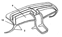
図1(a)に本発明のフレーム構造3を示す。フレーム構造3はコーナポイント10で集められる線状要素2を備えている。領域4が線状要素2により区分ないし包囲されているのが分かる。図1(a)に示すフレーム構造は自動車用の制御パネルのフレーム構造である。
FIG. 1A shows a
図1(b)に本発明の完全な制御パネル1を示す。制御パネル1は線状要素3を備えたフレーム構造3(理解を容易にするため図1(a)に別々に示す)を有している。線状要素2で区分されたフレーム構造の領域4は、少なくとも部分的にプラスチックのプラスチックシート要素5で塞ぐ。ここでプラスチックシート要素は線状要素2に単体材料結合で結合する。単体材料結合はここで、硬化後にプラスチックシート要素となる熱可塑性プラスチック材を射出成形することで行なうことができ、この過程中、単体材料結合がなされるように、線状要素に対してこのプラスチックの溶融、再溶融を行なう。
FIG. 1 (b) shows a complete control panel 1 of the present invention. The control panel 1 has a
図1(a)に示す制御パネルは更に、例えば発泡フィルムの装飾層やレザー、布製の装飾層で覆うことができる。 The control panel shown in FIG. 1A can be further covered with, for example, a decorative layer made of foamed film, a leather, or a decorative layer made of cloth.
図1(b)の実施例では線状要素2をシートメタルで形成したU字形の連続部品として実現している。
In the embodiment of FIG. 1B, the
これは断面Aに沿った図1(c)の断面から明かである。ここで「U」の開いた側面だけが外側に向けて開くように、U字形断面のまわりにプラスチックシート要素5をどのように注入したかが分かる。そこでUの内部に例えばケーブルなどを配置できる。当然、ケーブル11が滑り出さないようにUの開いた側に図示しない閉止要素を後に設けることができる。プラスチックシート要素は、ポリオレフィン化合物、ここではPP30LFG、即ち長さ10mm(射出成形法)と25mm(圧縮成形法)を有する挿入ファイバを有するポリプロピレンからなる。
This is apparent from the cross section of FIG. Here it can be seen how the
図1(d)に線状要素2から構築したフレーム構造3を示す。このフレーム構造は少なくとも部分的に、内部が中空で、プラスチックシート要素5に対するその側方アタッチメントに空気流の孔を有する線状要素2を有する。プラスチックシート要素5は車内に向けて多くの吐出開口部を有し、中空の線状要素2を通して誘導された空気の塊がプラスチックシート要素5から拡散し、平面状に流れるようにしている。
FIG. 1D shows a
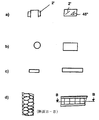
図2は線状要素のジオメトリィの様々な可能性を示している。ここで夫々左側に線状要素の実施例の部品の断面図を示し、右側にその側面図を示す。 FIG. 2 shows various possibilities for the geometry of the linear elements. Here, a sectional view of a part of an embodiment of a linear element is shown on the left side, and a side view thereof is shown on the right side.
図2(a)の左側にU字形の断面を(図1(c)と同様に)示すが、U字形の部材の両側からは更にウェブ2'が突出している。図2(a)の右側の側面図から、それらのウェブは傾斜しており、より詳細には水平に対して約45°傾斜していることが分かる。それにより、プラスチックシート要素で押出しコーティングする際、線状要素をプラスチックシート要素5に対してより良好に取付けできる。
A U-shaped cross section is shown on the left side of FIG. 2 (a) (similar to FIG. 1 (c)), but a web 2 'projects further from both sides of the U-shaped member. From the right side view of FIG. 2 (a), it can be seen that the webs are inclined, more specifically, about 45 ° to the horizontal. Thereby, the linear element can be better attached to the
図2(b)に線状要素の円状の断面を示す。右側の図2(b)から、それは一定の外径を有する「管状部品」であることが分かる。この管状の断面は例えばシートメタルないし穿孔シートメタルから作ることができ、また当然、ファイバから「巻いた」管とすることも可能である。 FIG. 2B shows a circular cross section of the linear element. From FIG. 2 (b) on the right, it can be seen that it is a “tubular part” having a constant outer diameter. This tubular cross section can be made, for example, from sheet metal or perforated sheet metal and, of course, can be a tube "rolled" from fiber.
図2(c)には平らな断面を示されている。ここで左側で、線状要素が長方形の断面を持つことが分かる。これはプラスチック材から形成するか、金属あるいはファイバ材(織りないし不織)から形成することができる。この変形はそれ自身で後に図3に示す製造上の変形を示している。 FIG. 2C shows a flat cross section. Here it can be seen on the left side that the linear element has a rectangular cross section. It can be formed from a plastic material or from a metal or fiber material (woven or non-woven). This variant itself represents the manufacturing variant shown later in FIG.
最後に図2(d)にハニカム・サンドウィッチ構造を示す。ここで図2(d)の右側に側面図を示す。ここでは上下のカバーパネル(このパネルも熱可塑性プラスチック材で含浸した布とすることができる)を備えた直立したハニカムセル(8角形)を見ることができる。これは左側の断面B−Bからより明確に分かる。 Finally, FIG. 2 (d) shows a honeycomb sandwich structure. Here, a side view is shown on the right side of FIG. Here, one can see an upright honeycomb cell (octagon) with upper and lower cover panels (which can also be cloth impregnated with thermoplastic material). This can be seen more clearly from the left section B-B.
本発明の制御パネルは様々な方法で製造することができる。このために、射出成形型のキャビティに線状要素を差込み、射出成形で少なくとも部分的にプラスチック材で再溶融して制御パネルを形成するのが特に簡単である。ここで1つの変形として、線状要素を事前に加工した自己支持フレーム(おおまかに図1(a)に示すフレームのように見える)として挿入し、圧力鋳造アルミニウムから形成することがある。 The control panel of the present invention can be manufactured in various ways. For this purpose, it is particularly simple to insert a linear element into the cavity of an injection mold and remelt at least partly with a plastic material by injection molding to form a control panel. Here, as a variant, the linear element may be inserted as a pre-processed self-supporting frame (roughly looks like the frame shown in FIG. 1 (a)) and formed from pressure cast aluminum.
しかし線状要素を個々の部品として型のキャビティに差込むのが非常に費用効果的なものとなる。このため、図3により特に有利な製造の変形をより詳細に説明する。 However, it is very cost effective to insert the linear elements as individual parts into the mold cavity. For this reason, a particularly advantageous manufacturing variant is described in more detail in FIG.
図3に射出成形型の断面を概略的に示す。これは第1の型半分8aとその上にある第2の型半分8bとからなる。それらの半分の型の間には、1−6mmの間隙高さcを持つ型キャビティ6がある。
FIG. 3 schematically shows a cross section of the injection mold. This consists of a
第1の型半分8aには断面がほぼ半円のくぼみ9aを有している。第2の型半分8bはその垂直方向に、くぼみに対して補足的な形状をしているがかなり小さいバルジ9bを有している。くぼみ9aはaの断面幅があり、バルジbはbの断面幅がある。cを関数としてbはaよりも小さい。
The
ここでくぼみ9aに沿って絡み合わせたファイバ(織りないし不織ファイバ布)からなる細片7を敷き、その細片が実質的にくぼみ9aの半円の断面を占めるようにすることができる。そして第2の型半分8bを最小間隔cまで下降させる。その後、型のキャビティ6内で熱可塑性プラスチック材の射出成形を行って、細片に含浸させ、更にプラスチックシート要素5をこの過程中にキャビティ6内で形成する。このように本発明の制御パネルを非常に費用効果的に製造することができる。
Here, it is possible to lay a strip 7 made of fibers (woven or non-woven fiber cloth) entangled along the
本発明の制御パネルはその固有の安定性の結果(即ちそのフレーム構造により)、従来の制御パネルよりもかなり安定的という利点がある。制御パネルは自動車の端壁や車体に直接、連結できる。本発明の制御パネルは自動車のクロスメンバで支持する必要はなくなる。 The control panel of the present invention has the advantage of being considerably more stable than a conventional control panel as a result of its inherent stability (ie, due to its frame structure). The control panel can be connected directly to the end wall or car body of the car. The control panel of the present invention does not need to be supported by a cross member of an automobile.
次に本発明の特に重要な点を別に再び強調する。 Next, a particularly important point of the present invention will be emphasized again.
この構造により断面が中空の線状要素の一体化が可能で、断面内部で延長している空洞を例えばケーブルあるいは室内換気のための空気流を誘導するのに使用できる。そこで特に図1(d)を再び参照する。室内を換気する構造は例えば、母体材料を通過する換気管を、その材料が最終的に硬化する前にそれを「吹き抜ける」ことで達成するように製造でき、そのため好適には型を形成する際に突起部分を設けて、空気口を形成する。 This structure allows the integration of linear elements with a hollow cross section, and a cavity extending within the cross section can be used, for example, to guide air flow for cables or room ventilation. Therefore, in particular, reference is again made to FIG. A room ventilation structure can be manufactured, for example, to achieve a ventilation tube that passes through the matrix material by “blowing” it before the material is finally cured, so it is preferably used when forming a mold. Protruding portions are provided on the air holes to form air ports.
本発明の特に重要な態様は、本発明により特に制御パネルの安定性が増加し、クロスメンバを省くことができる可能性があり、軽量構造という用件に合致するということである。 A particularly important aspect of the present invention is that the present invention particularly increases the stability of the control panel and may eliminate the cross member, meeting the requirement of a lightweight construction.
好適にはこれは、線状要素として例えば連続したファイバの束あるいはマット材の細片を挿入することで達成でき、マット材は単層あるいは複数層の不織ないし織物布として具体化する。この元となる考え方は、最も厳しく荷重がかかる点でも十分な安定性を常に持つため、全体的に同一強度を持つ安定した制御パネルを設計するのは高価になり、重量が増大するという本発明の考え方である。 Preferably, this can be achieved by inserting, for example, a continuous fiber bundle or mat strip as a linear element, the mat being embodied as a single layer or multiple layers of non-woven or woven fabric. Since this original idea always has sufficient stability even at the most severe load point, it is expensive to design a stable control panel with the same overall strength, and the weight increases. This is the idea.
このような関係から、延長している線が制御パネルで力の流れを再生する図1(a)を再度参照する。ここで例えばファイバ材の細片をそれらの力のフローラインに挿入することが可能である。特に高い力が働く力フローラインで、(より多くの材料あるいは特殊な材料を通して)特別な適合を行なうことができる。 From this relationship, reference is again made to FIG. 1A in which the extended line reproduces the force flow at the control panel. Here, for example, strips of fiber material can be inserted into the flow line of those forces. Special adaptations can be made (through more materials or special materials), especially in force flow lines where high forces are applied.
ファイバー材として、いくつかの材料が特に好ましいことが分かっている。そこで例えば織物グラスファイバーマットの細片を挿入することが可能である。それらは例えば事前に熱可塑性材料を含浸させることができ、あるいは例えばポリプロピレン糸のような熱可塑性糸を含めることができるので、それらを次に母体材料に合体させれば更にうまくいく(そのような製品は例えば「ベトロテック社」から入手可能)。そのようなすきまを持つ即ち事実上「マスク形態」の細片(ないし「小さくしたマット」)を挿入することが、サポートも大きなねじり応力を受ける場合に特にそれ自身をうかがわせる。 Several materials have been found to be particularly preferred as the fiber material. Thus, for example, it is possible to insert a strip of woven fiberglass mat. They can be pre-impregnated with a thermoplastic material, for example, or can include thermoplastic yarns, such as polypropylene yarns, so that they are then better combined with the matrix material (such as The product can be obtained from, for example, “Vetrotech”). Inserting a strip (or “smaller mat”) with such a clearance, or in effect a “mask form”, makes itself appear especially when the support is also subjected to a large torsional stress.
(例えばクロスメンバを取り換える際)、特に引張り荷重を吸収するため、連続的なグラスファイバないし連続グラスファイバの全ての束でガラスを設けることも可能である。ここでファイバ材は織物あるいは不織布ではなく、車体に取付けることもできる個々のファイバの束であり、クロスメンバの機能を請け負うものである。 It is also possible to provide glass with continuous glass fibers or all bundles of continuous glass fibers, especially to absorb tensile loads (for example when replacing the cross member). Here, the fiber material is not a woven fabric or non-woven fabric, but a bundle of individual fibers that can be attached to the vehicle body, and undertakes the function of the cross member.
従って特にその材料ないしその材料の量を(荷重によって)選択できるという利点がある。 Therefore, there is an advantage that the material or the amount of the material can be selected (depending on the load).
この関係で、更にいくつかの例を述べる。本発明でプラスチックシート要素を形成し、少なくとも部分的に線状要素を囲む母体材料は、好適には少なくとも部分的にファイバ材を貫通する比較的「安定した」材料で、この関係からきわめて安定しているにもかかわらず軽量の構造をもたらすことができる。ここで材料を「発泡」するだけでは一般に不十分で、ポリプロピレン(例えばPP30、30mm長のグラスファイバで強化したプロピレン(ポリプロピレン30LGF))などの安定したプラスチック材を使用した結合が最も可能性があり、代わりに例えば強化ないし非強化ポリアミドも可能である。ここで母体材料の張力の弾性係数は好適には2000N/m2以上であるべきで、特に3500N/m2以上であることが好ましい。しかし特に極端な適用では、22000N/m2以上の弾性係数を有する材料も達成可能である。ここでは例えば、異なる分離層を有する複数層のグラスファイバマットからなるサンドウィッチ構造を使用する。 In this connection, some examples will be described. The matrix material that forms the plastic sheet element in the present invention and at least partially surrounds the linear element is preferably a relatively “stable” material that at least partially penetrates the fiber material and is very stable in this regard. Despite being able to produce a lightweight structure. It is generally not sufficient to simply “foam” the material here, and bonding using a stable plastic material such as polypropylene (eg, PP30, propylene reinforced with 30 mm long glass fiber (polypropylene 30 LGF)) is most likely. Alternatively, for example, reinforced or unreinforced polyamides are possible. Wherein the elastic modulus of tension of the base material is preferably should be 2000N / m 2 or more and in particular 3500 N / m 2 or more. However, in particularly extreme applications, materials with an elastic modulus of 22000 N / m 2 or more can also be achieved. Here, for example, a sandwich structure composed of a plurality of glass fiber mats having different separation layers is used.
ファイバ材を母体材料に結合するには更に別の可能な方法がある。 There are still other possible ways to bond the fiber material to the matrix material.
それほど大きくない応力を受けない部品の場合、例えばPP30LGFの溶融物を射出成形により型に導入するだけ(例えば図3に示すもの)で十分であり得る。しかし射出成形過程故に、安定性にむしろ否定的な効果があるファイバの短小化が生じる。 For parts that are not subject to too much stress, it may be sufficient, for example, to introduce a melt of PP30LGF into the mold by injection molding (eg as shown in FIG. 3). However, the injection molding process results in fiber shortening that has a rather negative effect on stability.
この代替方法として、適切なニ型に押出し機から直接溶融物を例えばストランドの形で入れ、型で押圧することも当然可能であり、そこで母体材料によるファイバ材の浸透が生じる(この方法は「ストランド沈着として知られている」)。基本的に本発明では、これらの方法を全て使用でき、例えばファイバ材の細片を閉じた型内で母体材料と結合させることができる。ここで、図3に示すように、型の成形により細片の輪郭を決め、それにより後の構成部品の輪郭を決めておくことが当然、可能で好ましい。更に図3に示す多少円形の構造とは異なり、より角ばった構造、即ち断面が多角形でも可能である。当然、対応する輪郭を省くことも可能である(ある状況では、荷重支持能力の小さな損失が伴う)。 As an alternative to this, it is of course also possible to put the melt directly into the appropriate die from the extruder, for example in the form of strands, and press it with the mold, where the penetration of the fiber material by the matrix material occurs (this method “ Known as strand deposition "). Basically, all of these methods can be used in the present invention, for example, a strip of fiber material can be combined with a host material in a closed mold. Here, as shown in FIG. 3, it is naturally possible and preferable to determine the contour of the strip by forming a mold and thereby determine the contour of the subsequent component. Further, unlike the somewhat circular structure shown in FIG. 3, a more angular structure, that is, a polygonal cross section is possible. Of course, it is also possible to omit the corresponding contours (in some situations with a small loss of load carrying capacity).
しかし基本的に、特に荷重が高い場合、あるいは荷重タイプに適合する場合、特定の材料を使用することができる(例えば引張り荷重の場合は連続糸あるいは例えば付加的な強力なねじり荷重を吸収する場合は3次元的に曲げられたマット材)ことは本発明にとって本質的なことである。 Basically, however, certain materials can be used, especially if the load is high or if it is compatible with the load type (eg continuous yarn in the case of tensile loads or to absorb additional strong torsional loads, for example) It is essential to the present invention that the mat material is three-dimensionally bent.
Claims (14)
8. A vehicle including a control panel according to claim 1, wherein the frame structure (3) can be directly coupled to an end wall or vehicle body of the vehicle.
Applications Claiming Priority (2)
| Application Number | Priority Date | Filing Date | Title |
|---|---|---|---|
| DE10257161A DE10257161A1 (en) | 2002-12-02 | 2002-12-02 | Instrument panel and process for its manufacture |
| PCT/EP2003/013509 WO2004050409A1 (en) | 2002-12-02 | 2003-12-01 | Control panel and method for the production thereof |
Publications (1)
| Publication Number | Publication Date |
|---|---|
| JP2006507982A true JP2006507982A (en) | 2006-03-09 |
Family
ID=32318993
Family Applications (1)
| Application Number | Title | Priority Date | Filing Date |
|---|---|---|---|
| JP2004556248A Pending JP2006507982A (en) | 2002-12-02 | 2003-12-01 | Control panel and control panel manufacturing method |
Country Status (10)
| Country | Link |
|---|---|
| US (1) | US20060145506A1 (en) |
| EP (2) | EP1567385B1 (en) |
| JP (1) | JP2006507982A (en) |
| CN (1) | CN100491152C (en) |
| AT (2) | ATE498508T1 (en) |
| AU (1) | AU2003288206A1 (en) |
| DE (4) | DE10257161A1 (en) |
| ES (1) | ES2357973T3 (en) |
| MX (1) | MXPA05005789A (en) |
| WO (1) | WO2004050409A1 (en) |
Families Citing this family (16)
| Publication number | Priority date | Publication date | Assignee | Title |
|---|---|---|---|---|
| DE102005039125B3 (en) * | 2005-08-15 | 2006-09-21 | Faurecia Innenraum Systeme Gmbh | Instrument panel arrangement for use in motor vehicle, has instrument panel having one part displaceable into internal space of motor vehicle relative to instrument panel support by using actuators |
| US20070228762A1 (en) * | 2006-04-03 | 2007-10-04 | Visteon Global Technologies, Inc. | Instrument panel with exposed support structure and method of formation |
| FR2902369B1 (en) * | 2006-06-16 | 2011-05-06 | Faurecia Interieur Ind | FORCED VENTILATION SYSTEM FOR THE CABIN OF A MOTOR VEHICLE, AND CORRESPONDING BOARDBOARD. |
| US7798548B2 (en) * | 2007-01-03 | 2010-09-21 | Gm Global Technology Operations, Inc. | Soft composite trim panel for a vehicle interior |
| DE102008006936A1 (en) | 2007-07-26 | 2009-02-05 | Faurecia Innenraum Systeme Gmbh | Integrated center reinforcement |
| DE102009006960A1 (en) | 2009-01-31 | 2010-08-05 | Aksys Gmbh | Plastic-metal hybrid vehicle-dashboard-assembly support for motor vehicle, has cross member determined for absorbing side impact forces, where support is made from support structure and cross member by pressing and/or injection molding |
| US20110027607A1 (en) * | 2009-07-30 | 2011-02-03 | Magna Seating Inc. | Magnesium hybrid parts and processes |
| DE102010021123B4 (en) | 2010-05-21 | 2016-08-18 | International Automotive Components Group Gmbh | Mold part and method for producing a molded part, in particular a molded part for a motor vehicle, such as a dashboard or a center console |
| JP4918153B2 (en) * | 2010-07-02 | 2012-04-18 | 本田技研工業株式会社 | Body front structure |
| DE102011007668B4 (en) * | 2011-04-19 | 2019-04-25 | Shanghai Yanfeng Jinqiao Automotive Trim Systems Co., Ltd. | Instrument panel for a vehicle |
| GB2521370A (en) * | 2013-12-17 | 2015-06-24 | Prodrive Composites Ltd | A product and a method of making a product |
| DE102015226019A1 (en) * | 2015-12-18 | 2017-06-22 | Sitech Sitztechnik Gmbh | Fiber composite component and method for producing a fiber composite component |
| US11440283B2 (en) * | 2018-02-02 | 2022-09-13 | The Boeing Company | Composite sandwich panels with over-crushed edge regions |
| DE102018128404A1 (en) | 2018-11-13 | 2020-05-14 | Bayerische Motoren Werke Aktiengesellschaft | Bulkhead module |
| DE102018133306A1 (en) * | 2018-12-21 | 2020-06-25 | Bayerische Motoren Werke Aktiengesellschaft | Motor vehicle component with light function |
| DE102019216518B3 (en) * | 2019-10-25 | 2021-03-25 | Magna Exteriors Gmbh | Vehicle door and its method for producing a vehicle door |
Family Cites Families (20)
| Publication number | Priority date | Publication date | Assignee | Title |
|---|---|---|---|---|
| US3141811A (en) * | 1958-04-01 | 1964-07-21 | Johns Manville Fiber Glass Inc | Fibrous laminate and method of producing the same |
| US3042137A (en) * | 1959-09-09 | 1962-07-03 | Gen Motors Corp | Vehicle instrument and dashboard assemblies |
| US3130807A (en) * | 1962-07-05 | 1964-04-28 | Bobby R Mchenry | Air cushion dashboard for automobiles and the like |
| JPS5113298B2 (en) * | 1971-10-20 | 1976-04-27 | ||
| DE3012007A1 (en) * | 1980-03-28 | 1981-10-08 | Gebr. Happich Gmbh, 5600 Wuppertal | FOAM BODY, IN PARTICULAR DASHBOARD FOR MOTOR VEHICLES |
| DE3016199A1 (en) * | 1980-04-26 | 1981-11-05 | Fa. Carl Freudenberg, 6940 Weinheim | DASHBOARD FOR MOTOR VEHICLES |
| DE3611486C2 (en) * | 1986-04-05 | 1994-04-21 | Audi Ag | Dashboard for motor vehicles |
| US5273597A (en) | 1988-11-26 | 1993-12-28 | Honda Giken Kogyo Kabushiki Kaisha | Trim member for motor vehicle and method of and system for manufacturing the same |
| US5333901A (en) * | 1993-04-26 | 1994-08-02 | General Motors Corporation | Air bag deployable instrument panel cover |
| US5487800A (en) * | 1994-01-24 | 1996-01-30 | Davidson Textron Inc. | Method of making a covered article by vacuum drawing |
| GB9423776D0 (en) * | 1994-11-25 | 1995-01-11 | Acg Deutschland Gmbh | Dashboard assembly |
| US5564515A (en) * | 1995-08-23 | 1996-10-15 | Chrysler Corporation | Instrument panel assembly |
| US5762395A (en) * | 1996-06-25 | 1998-06-09 | General Motors Corporation | Molded cross car support structure |
| JP2001018033A (en) * | 1999-07-01 | 2001-01-23 | Daido Steel Co Ltd | Manufacture of mold for precision casting |
| US6354623B1 (en) * | 2000-08-03 | 2002-03-12 | Textron Automotive Company Inc. | Automotive trim panel |
| PT1350711E (en) * | 2002-03-27 | 2006-12-29 | Denso Thermal Systems Spa | Hybrid support structure for a vehicle dashboard and method for manufacturing the same |
| US6621688B1 (en) * | 2002-06-26 | 2003-09-16 | Alcoa Fujikura Limited | Electrical distribution system having integral junction box for instrument panel application |
| DE10251761A1 (en) * | 2002-11-05 | 2004-05-19 | Behr Gmbh & Co. | Cross-member forming part of hybrid structure frame for road vehicle has foundation body with U-section groove detouring round centrally mounted heater or air conditioner and holding air duct |
| US20040256878A1 (en) * | 2003-06-20 | 2004-12-23 | Jsp Licenses, Inc. | Fragmentation-resistant instrument panel and method of making same |
| US20050183897A1 (en) * | 2004-02-24 | 2005-08-25 | Lear Corporation | Two-shot co-injected automotive interior trim assembly and method |
-
2002
- 2002-12-02 DE DE10257161A patent/DE10257161A1/en not_active Ceased
-
2003
- 2003-12-01 EP EP03780094A patent/EP1567385B1/en not_active Expired - Lifetime
- 2003-12-01 AT AT07076096T patent/ATE498508T1/en active
- 2003-12-01 DE DE50313482T patent/DE50313482D1/en not_active Expired - Lifetime
- 2003-12-01 US US10/537,111 patent/US20060145506A1/en not_active Abandoned
- 2003-12-01 DE DE50310175T patent/DE50310175D1/en not_active Expired - Lifetime
- 2003-12-01 MX MXPA05005789A patent/MXPA05005789A/en active IP Right Grant
- 2003-12-01 AT AT03780094T patent/ATE401212T1/en not_active IP Right Cessation
- 2003-12-01 ES ES07076096T patent/ES2357973T3/en not_active Expired - Lifetime
- 2003-12-01 DE DE20321578U patent/DE20321578U1/en not_active Expired - Lifetime
- 2003-12-01 EP EP07076096A patent/EP1925488B1/en not_active Expired - Lifetime
- 2003-12-01 AU AU2003288206A patent/AU2003288206A1/en not_active Abandoned
- 2003-12-01 JP JP2004556248A patent/JP2006507982A/en active Pending
- 2003-12-01 WO PCT/EP2003/013509 patent/WO2004050409A1/en active IP Right Grant
- 2003-12-01 CN CNB2003801048794A patent/CN100491152C/en not_active Expired - Fee Related
Also Published As
| Publication number | Publication date |
|---|---|
| ES2357973T3 (en) | 2011-05-04 |
| US20060145506A1 (en) | 2006-07-06 |
| CN100491152C (en) | 2009-05-27 |
| EP1567385A1 (en) | 2005-08-31 |
| DE50313482D1 (en) | 2011-03-31 |
| ATE498508T1 (en) | 2011-03-15 |
| MXPA05005789A (en) | 2005-10-18 |
| EP1925488A2 (en) | 2008-05-28 |
| EP1925488B1 (en) | 2011-02-16 |
| DE10257161A1 (en) | 2004-06-17 |
| AU2003288206A1 (en) | 2004-06-23 |
| CN1720154A (en) | 2006-01-11 |
| WO2004050409A1 (en) | 2004-06-17 |
| EP1925488A3 (en) | 2008-06-18 |
| DE50310175D1 (en) | 2008-08-28 |
| EP1567385B1 (en) | 2008-07-16 |
| ATE401212T1 (en) | 2008-08-15 |
| DE20321578U1 (en) | 2008-03-06 |
Similar Documents
| Publication | Publication Date | Title |
|---|---|---|
| JP2006507982A (en) | Control panel and control panel manufacturing method | |
| US9272606B2 (en) | Vehicle side door structure and method of making and using the same | |
| US6821613B1 (en) | Structural component consisting of fiber-reinforced thermoplastic plastic | |
| US11820088B2 (en) | Structural reinforcements | |
| US10137649B2 (en) | Steering column produced from fibre-composite and on the basis of pultrusion, braiding and/or winding technology | |
| US6423388B1 (en) | Composite vehicle seat back frame and method of manufacturing same | |
| JP6486339B2 (en) | Side panel assembly for passenger cars | |
| CN105829048A (en) | Carrier with localized fibrous insert and methods | |
| US20060097539A1 (en) | Inherently rigid instrument carrier assembly | |
| EP3268217A1 (en) | Pultruded articles and methods for making same | |
| DE102011111743B4 (en) | FRP-component | |
| JPH0639929A (en) | Production of fiber-reinforced plastic girder material for automoble bumper and reinforced plastic girder material | |
| US20170368767A1 (en) | Composite molding techniques | |
| US9950679B2 (en) | Fabrication method for making an equipment device for an automotive vehicle and associated equipment device for an automotive vehicle comprising a composite body | |
| DE102011111744A1 (en) | Control box module and manufacturing process | |
| DE102018214004A1 (en) | Vehicle component reinforced by means of discarding technology, and device and method for production | |
| KR102047752B1 (en) | Composite fiber component and method for producing a composite fiber component | |
| JP5179952B2 (en) | Hollow molded product and method for producing hollow molded product | |
| JP2021045934A (en) | Fiber-reinforced resin composite material |
Legal Events
| Date | Code | Title | Description |
|---|---|---|---|
| A621 | Written request for application examination |
Free format text: JAPANESE INTERMEDIATE CODE: A621 Effective date: 20060216 |
|
| A131 | Notification of reasons for refusal |
Free format text: JAPANESE INTERMEDIATE CODE: A131 Effective date: 20080422 |
|
| A521 | Request for written amendment filed |
Free format text: JAPANESE INTERMEDIATE CODE: A523 Effective date: 20080710 |
|
| A521 | Request for written amendment filed |
Free format text: JAPANESE INTERMEDIATE CODE: A523 Effective date: 20080730 |
|
| A131 | Notification of reasons for refusal |
Free format text: JAPANESE INTERMEDIATE CODE: A131 Effective date: 20090120 |
|
| A601 | Written request for extension of time |
Free format text: JAPANESE INTERMEDIATE CODE: A601 Effective date: 20090417 |
|
| A602 | Written permission of extension of time |
Free format text: JAPANESE INTERMEDIATE CODE: A602 Effective date: 20090424 |
|
| A601 | Written request for extension of time |
Free format text: JAPANESE INTERMEDIATE CODE: A601 Effective date: 20090519 |
|
| A602 | Written permission of extension of time |
Free format text: JAPANESE INTERMEDIATE CODE: A602 Effective date: 20090526 |
|
| A02 | Decision of refusal |
Free format text: JAPANESE INTERMEDIATE CODE: A02 Effective date: 20090929 |