EP1925488B1 - Instrument panel and method for its manufacture - Google Patents
Instrument panel and method for its manufacture Download PDFInfo
- Publication number
- EP1925488B1 EP1925488B1 EP07076096A EP07076096A EP1925488B1 EP 1925488 B1 EP1925488 B1 EP 1925488B1 EP 07076096 A EP07076096 A EP 07076096A EP 07076096 A EP07076096 A EP 07076096A EP 1925488 B1 EP1925488 B1 EP 1925488B1
- Authority
- EP
- European Patent Office
- Prior art keywords
- motor vehicle
- dashboard
- elements
- frame structure
- instrument panel
- Prior art date
- Legal status (The legal status is an assumption and is not a legal conclusion. Google has not performed a legal analysis and makes no representation as to the accuracy of the status listed.)
- Expired - Lifetime
Links
Images


Classifications
-
- B—PERFORMING OPERATIONS; TRANSPORTING
- B29—WORKING OF PLASTICS; WORKING OF SUBSTANCES IN A PLASTIC STATE IN GENERAL
- B29C—SHAPING OR JOINING OF PLASTICS; SHAPING OF MATERIAL IN A PLASTIC STATE, NOT OTHERWISE PROVIDED FOR; AFTER-TREATMENT OF THE SHAPED PRODUCTS, e.g. REPAIRING
- B29C43/00—Compression moulding, i.e. applying external pressure to flow the moulding material; Apparatus therefor
- B29C43/003—Compression moulding, i.e. applying external pressure to flow the moulding material; Apparatus therefor characterised by the choice of material
-
- B—PERFORMING OPERATIONS; TRANSPORTING
- B29—WORKING OF PLASTICS; WORKING OF SUBSTANCES IN A PLASTIC STATE IN GENERAL
- B29C—SHAPING OR JOINING OF PLASTICS; SHAPING OF MATERIAL IN A PLASTIC STATE, NOT OTHERWISE PROVIDED FOR; AFTER-TREATMENT OF THE SHAPED PRODUCTS, e.g. REPAIRING
- B29C45/00—Injection moulding, i.e. forcing the required volume of moulding material through a nozzle into a closed mould; Apparatus therefor
- B29C45/14—Injection moulding, i.e. forcing the required volume of moulding material through a nozzle into a closed mould; Apparatus therefor incorporating preformed parts or layers, e.g. injection moulding around inserts or for coating articles
- B29C45/14631—Coating reinforcements
-
- B—PERFORMING OPERATIONS; TRANSPORTING
- B29—WORKING OF PLASTICS; WORKING OF SUBSTANCES IN A PLASTIC STATE IN GENERAL
- B29C—SHAPING OR JOINING OF PLASTICS; SHAPING OF MATERIAL IN A PLASTIC STATE, NOT OTHERWISE PROVIDED FOR; AFTER-TREATMENT OF THE SHAPED PRODUCTS, e.g. REPAIRING
- B29C45/00—Injection moulding, i.e. forcing the required volume of moulding material through a nozzle into a closed mould; Apparatus therefor
- B29C45/17—Component parts, details or accessories; Auxiliary operations
- B29C45/1703—Introducing an auxiliary fluid into the mould
- B29C45/1704—Introducing an auxiliary fluid into the mould the fluid being introduced into the interior of the injected material which is still in a molten state, e.g. for producing hollow articles
-
- B—PERFORMING OPERATIONS; TRANSPORTING
- B29—WORKING OF PLASTICS; WORKING OF SUBSTANCES IN A PLASTIC STATE IN GENERAL
- B29C—SHAPING OR JOINING OF PLASTICS; SHAPING OF MATERIAL IN A PLASTIC STATE, NOT OTHERWISE PROVIDED FOR; AFTER-TREATMENT OF THE SHAPED PRODUCTS, e.g. REPAIRING
- B29C70/00—Shaping composites, i.e. plastics material comprising reinforcements, fillers or preformed parts, e.g. inserts
- B29C70/04—Shaping composites, i.e. plastics material comprising reinforcements, fillers or preformed parts, e.g. inserts comprising reinforcements only, e.g. self-reinforcing plastics
- B29C70/28—Shaping operations therefor
- B29C70/40—Shaping or impregnating by compression not applied
- B29C70/42—Shaping or impregnating by compression not applied for producing articles of definite length, i.e. discrete articles
- B29C70/46—Shaping or impregnating by compression not applied for producing articles of definite length, i.e. discrete articles using matched moulds, e.g. for deforming sheet moulding compounds [SMC] or prepregs
- B29C70/48—Shaping or impregnating by compression not applied for producing articles of definite length, i.e. discrete articles using matched moulds, e.g. for deforming sheet moulding compounds [SMC] or prepregs and impregnating the reinforcements in the closed mould, e.g. resin transfer moulding [RTM], e.g. by vacuum
-
- B—PERFORMING OPERATIONS; TRANSPORTING
- B29—WORKING OF PLASTICS; WORKING OF SUBSTANCES IN A PLASTIC STATE IN GENERAL
- B29C—SHAPING OR JOINING OF PLASTICS; SHAPING OF MATERIAL IN A PLASTIC STATE, NOT OTHERWISE PROVIDED FOR; AFTER-TREATMENT OF THE SHAPED PRODUCTS, e.g. REPAIRING
- B29C70/00—Shaping composites, i.e. plastics material comprising reinforcements, fillers or preformed parts, e.g. inserts
- B29C70/88—Shaping composites, i.e. plastics material comprising reinforcements, fillers or preformed parts, e.g. inserts characterised primarily by possessing specific properties, e.g. electrically conductive or locally reinforced
- B29C70/882—Shaping composites, i.e. plastics material comprising reinforcements, fillers or preformed parts, e.g. inserts characterised primarily by possessing specific properties, e.g. electrically conductive or locally reinforced partly or totally electrically conductive, e.g. for EMI shielding
- B29C70/885—Shaping composites, i.e. plastics material comprising reinforcements, fillers or preformed parts, e.g. inserts characterised primarily by possessing specific properties, e.g. electrically conductive or locally reinforced partly or totally electrically conductive, e.g. for EMI shielding with incorporated metallic wires, nets, films or plates
-
- B—PERFORMING OPERATIONS; TRANSPORTING
- B60—VEHICLES IN GENERAL
- B60R—VEHICLES, VEHICLE FITTINGS, OR VEHICLE PARTS, NOT OTHERWISE PROVIDED FOR
- B60R13/00—Elements for body-finishing, identifying, or decorating; Arrangements or adaptations for advertising purposes
- B60R13/02—Internal Trim mouldings ; Internal Ledges; Wall liners for passenger compartments; Roof liners
- B60R13/0256—Dashboard liners
-
- B—PERFORMING OPERATIONS; TRANSPORTING
- B62—LAND VEHICLES FOR TRAVELLING OTHERWISE THAN ON RAILS
- B62D—MOTOR VEHICLES; TRAILERS
- B62D25/00—Superstructure or monocoque structure sub-units; Parts or details thereof not otherwise provided for
- B62D25/08—Front or rear portions
- B62D25/14—Dashboards as superstructure sub-units
- B62D25/145—Dashboards as superstructure sub-units having a crossbeam incorporated therein
-
- B—PERFORMING OPERATIONS; TRANSPORTING
- B29—WORKING OF PLASTICS; WORKING OF SUBSTANCES IN A PLASTIC STATE IN GENERAL
- B29C—SHAPING OR JOINING OF PLASTICS; SHAPING OF MATERIAL IN A PLASTIC STATE, NOT OTHERWISE PROVIDED FOR; AFTER-TREATMENT OF THE SHAPED PRODUCTS, e.g. REPAIRING
- B29C45/00—Injection moulding, i.e. forcing the required volume of moulding material through a nozzle into a closed mould; Apparatus therefor
- B29C45/17—Component parts, details or accessories; Auxiliary operations
- B29C45/1703—Introducing an auxiliary fluid into the mould
- B29C45/1704—Introducing an auxiliary fluid into the mould the fluid being introduced into the interior of the injected material which is still in a molten state, e.g. for producing hollow articles
- B29C2045/1724—Introducing an auxiliary fluid into the mould the fluid being introduced into the interior of the injected material which is still in a molten state, e.g. for producing hollow articles hollows used as conduits
-
- B—PERFORMING OPERATIONS; TRANSPORTING
- B29—WORKING OF PLASTICS; WORKING OF SUBSTANCES IN A PLASTIC STATE IN GENERAL
- B29C—SHAPING OR JOINING OF PLASTICS; SHAPING OF MATERIAL IN A PLASTIC STATE, NOT OTHERWISE PROVIDED FOR; AFTER-TREATMENT OF THE SHAPED PRODUCTS, e.g. REPAIRING
- B29C45/00—Injection moulding, i.e. forcing the required volume of moulding material through a nozzle into a closed mould; Apparatus therefor
- B29C45/14—Injection moulding, i.e. forcing the required volume of moulding material through a nozzle into a closed mould; Apparatus therefor incorporating preformed parts or layers, e.g. injection moulding around inserts or for coating articles
- B29C45/14311—Injection moulding, i.e. forcing the required volume of moulding material through a nozzle into a closed mould; Apparatus therefor incorporating preformed parts or layers, e.g. injection moulding around inserts or for coating articles using means for bonding the coating to the articles
-
- B—PERFORMING OPERATIONS; TRANSPORTING
- B29—WORKING OF PLASTICS; WORKING OF SUBSTANCES IN A PLASTIC STATE IN GENERAL
- B29C—SHAPING OR JOINING OF PLASTICS; SHAPING OF MATERIAL IN A PLASTIC STATE, NOT OTHERWISE PROVIDED FOR; AFTER-TREATMENT OF THE SHAPED PRODUCTS, e.g. REPAIRING
- B29C45/00—Injection moulding, i.e. forcing the required volume of moulding material through a nozzle into a closed mould; Apparatus therefor
- B29C45/14—Injection moulding, i.e. forcing the required volume of moulding material through a nozzle into a closed mould; Apparatus therefor incorporating preformed parts or layers, e.g. injection moulding around inserts or for coating articles
- B29C45/14467—Joining articles or parts of a single article
-
- B—PERFORMING OPERATIONS; TRANSPORTING
- B29—WORKING OF PLASTICS; WORKING OF SUBSTANCES IN A PLASTIC STATE IN GENERAL
- B29C—SHAPING OR JOINING OF PLASTICS; SHAPING OF MATERIAL IN A PLASTIC STATE, NOT OTHERWISE PROVIDED FOR; AFTER-TREATMENT OF THE SHAPED PRODUCTS, e.g. REPAIRING
- B29C45/00—Injection moulding, i.e. forcing the required volume of moulding material through a nozzle into a closed mould; Apparatus therefor
- B29C45/14—Injection moulding, i.e. forcing the required volume of moulding material through a nozzle into a closed mould; Apparatus therefor incorporating preformed parts or layers, e.g. injection moulding around inserts or for coating articles
- B29C45/14778—Injection moulding, i.e. forcing the required volume of moulding material through a nozzle into a closed mould; Apparatus therefor incorporating preformed parts or layers, e.g. injection moulding around inserts or for coating articles the article consisting of a material with particular properties, e.g. porous, brittle
-
- B—PERFORMING OPERATIONS; TRANSPORTING
- B29—WORKING OF PLASTICS; WORKING OF SUBSTANCES IN A PLASTIC STATE IN GENERAL
- B29C—SHAPING OR JOINING OF PLASTICS; SHAPING OF MATERIAL IN A PLASTIC STATE, NOT OTHERWISE PROVIDED FOR; AFTER-TREATMENT OF THE SHAPED PRODUCTS, e.g. REPAIRING
- B29C70/00—Shaping composites, i.e. plastics material comprising reinforcements, fillers or preformed parts, e.g. inserts
- B29C70/04—Shaping composites, i.e. plastics material comprising reinforcements, fillers or preformed parts, e.g. inserts comprising reinforcements only, e.g. self-reinforcing plastics
- B29C70/28—Shaping operations therefor
- B29C70/40—Shaping or impregnating by compression not applied
- B29C70/42—Shaping or impregnating by compression not applied for producing articles of definite length, i.e. discrete articles
- B29C70/46—Shaping or impregnating by compression not applied for producing articles of definite length, i.e. discrete articles using matched moulds, e.g. for deforming sheet moulding compounds [SMC] or prepregs
-
- B—PERFORMING OPERATIONS; TRANSPORTING
- B29—WORKING OF PLASTICS; WORKING OF SUBSTANCES IN A PLASTIC STATE IN GENERAL
- B29K—INDEXING SCHEME ASSOCIATED WITH SUBCLASSES B29B, B29C OR B29D, RELATING TO MOULDING MATERIALS OR TO MATERIALS FOR MOULDS, REINFORCEMENTS, FILLERS OR PREFORMED PARTS, e.g. INSERTS
- B29K2023/00—Use of polyalkenes or derivatives thereof as moulding material
- B29K2023/10—Polymers of propylene
- B29K2023/12—PP, i.e. polypropylene
-
- B—PERFORMING OPERATIONS; TRANSPORTING
- B29—WORKING OF PLASTICS; WORKING OF SUBSTANCES IN A PLASTIC STATE IN GENERAL
- B29K—INDEXING SCHEME ASSOCIATED WITH SUBCLASSES B29B, B29C OR B29D, RELATING TO MOULDING MATERIALS OR TO MATERIALS FOR MOULDS, REINFORCEMENTS, FILLERS OR PREFORMED PARTS, e.g. INSERTS
- B29K2077/00—Use of PA, i.e. polyamides, e.g. polyesteramides or derivatives thereof, as moulding material
-
- B—PERFORMING OPERATIONS; TRANSPORTING
- B29—WORKING OF PLASTICS; WORKING OF SUBSTANCES IN A PLASTIC STATE IN GENERAL
- B29K—INDEXING SCHEME ASSOCIATED WITH SUBCLASSES B29B, B29C OR B29D, RELATING TO MOULDING MATERIALS OR TO MATERIALS FOR MOULDS, REINFORCEMENTS, FILLERS OR PREFORMED PARTS, e.g. INSERTS
- B29K2309/00—Use of inorganic materials not provided for in groups B29K2303/00 - B29K2307/00, as reinforcement
- B29K2309/08—Glass
-
- B—PERFORMING OPERATIONS; TRANSPORTING
- B29—WORKING OF PLASTICS; WORKING OF SUBSTANCES IN A PLASTIC STATE IN GENERAL
- B29K—INDEXING SCHEME ASSOCIATED WITH SUBCLASSES B29B, B29C OR B29D, RELATING TO MOULDING MATERIALS OR TO MATERIALS FOR MOULDS, REINFORCEMENTS, FILLERS OR PREFORMED PARTS, e.g. INSERTS
- B29K2705/00—Use of metals, their alloys or their compounds, for preformed parts, e.g. for inserts
-
- B—PERFORMING OPERATIONS; TRANSPORTING
- B29—WORKING OF PLASTICS; WORKING OF SUBSTANCES IN A PLASTIC STATE IN GENERAL
- B29L—INDEXING SCHEME ASSOCIATED WITH SUBCLASS B29C, RELATING TO PARTICULAR ARTICLES
- B29L2031/00—Other particular articles
- B29L2031/30—Vehicles, e.g. ships or aircraft, or body parts thereof
- B29L2031/3005—Body finishings
- B29L2031/3008—Instrument panels
-
- B—PERFORMING OPERATIONS; TRANSPORTING
- B60—VEHICLES IN GENERAL
- B60Y—INDEXING SCHEME RELATING TO ASPECTS CROSS-CUTTING VEHICLE TECHNOLOGY
- B60Y2306/00—Other features of vehicle sub-units
- B60Y2306/09—Reducing noise
-
- B—PERFORMING OPERATIONS; TRANSPORTING
- B60—VEHICLES IN GENERAL
- B60Y—INDEXING SCHEME RELATING TO ASPECTS CROSS-CUTTING VEHICLE TECHNOLOGY
- B60Y2410/00—Constructional features of vehicle sub-units
- B60Y2410/12—Production or manufacturing of vehicle parts
Definitions
- the present invention relates to a method for manufacturing an instrument panel, and a motor vehicle comprising an instrument panel produced by this method.
- instrument panels for motor vehicles There are various embodiments of instrument panels for motor vehicles known.
- instrument panels are e.g. mounted on a arranged between the A-pillars of a motor vehicle crossmember.
- the instrument panels themselves usually still have an additional support structure on which a shell of mostly injection-molded plastic is supported, which can be occupied on the vehicle interior side with a decorative layer.
- the present invention is therefore an object of the invention to provide a method for producing an instrument panel, which guarantees that on the one hand highly resilient instrument panel is given and this is also lightweight, inexpensive and safe.
- the frame structure or the materially connected thereto plastic elements are directly covered with a decorative layer, and on the other hand, the force-absorbing frame structure of the instrument panel is directly connected to an end wall and / or a motor vehicle body.
- the frame structure is in this case designed such that a running between the A-pillars of the motor vehicle cross member is dispensable.
- the frame structure is in this case calculated so that the forces acting on the instrument panel are absorbed mainly by their appropriate structure.
- the plastic plate elements which also contribute to a stiffening of the instrument panel, as they are materially connected in their edge regions with the line-shaped elements.
- Under cohesive connection is meant primarily a remelting or melting of liquid plastic to the linear elements.
- the plastic plate elements are hereby introduced in an injection molding process as a liquid plastic in a corresponding mold, in which the line-shaped elements are provided.
- the whole cockpit area is seen as a "big cuboid".
- the loads are defined (eg “abuse forces", as they may arise in the airbag deployment or a "jacket direction test” on the steering wheel).
- areas are defined in which a free space should lie, so areas in which the cuboid must be "cut out", for example, footwell for vehicle occupants to create. There can then be no structure.
- An adapted "grid profile” is modeled on this. Line-shaped elements of a frame structure are then arranged along these grid lines.
- the inventive method is a method for producing an instrument panel and attaching the same in a motor vehicle, wherein a built-up of linear elements frame structure, which is partially closed with plastic plate elements is covered with a decorative layer, wherein the frame structure is designed such that a between the A -Columns of the motor vehicle extending cross member is dispensable and the frame structure is connected directly to an end wall and / or the vehicle body.
- the cross section of the linear elements in the installed state in the instrument panel is U-shaped, round, oval or polygonal. Principally closed or open cross-sections can be used here. It should be noted here that the linear elements in the installed state can also serve to guide cables or to guide the air. Particularly advantageous is, for example, a U-profile, which is open to the outside of the instrument panel, so that, for example, cable harnesses can be easily accessed from outside in this U-profile.
- the line-shaped element is a strip of honeycomb sandwich structure.
- honeycomb sandwich structure e.g. several adjacent honeycomb octagons provided, which are enclosed between two cover plates. This results in a very easy-to-build structure with very good strength values.
- the line-shaped elements have special webs on their outside. These are initially used to stiffen the linear element itself, but it is thereby given an increase in the coupling surface of the plastic to be encapsulated. It has been found that for reasons of stability it is particularly favorable to arrange the webs in each case inclined (for example 45 °) to the main course direction of the linear element itself in order to achieve the highest possible stability and integration of the linear element in the instrument panel.
- the line-shaped elements made of sheet metal, such as sheet steel, perforated metal sheet or eg made of aluminum or magnesium.
- fiber materials such as sheet steel, perforated metal sheet or eg made of aluminum or magnesium.
- strip-shaped woven fabrics or knitted fabrics can be used, which unfold their full strength only in the encapsulation process.
- the linear elements be made of continuous fibers. These are, for example, tubes made of continuous fibers, as base fibers here glass fibers or carbon fibers are used, which are already bound for example before spraying with a thermoplastic material. The subsequent encapsulation with the plastic, which forms the later plastic plate elements, results in a particularly good fusion of these linear elements in the forest.
- the plastic plate elements may be formed of different plastics.
- these are made of a thermoplastic material, e.g. made of PP30LGF, a polypropylene material with long fiber content.
- These long fiber parts are glass fibers, in the injection molding process according to the invention, these glass fibers preferably have a length of 10 mm.
- Alternative plastics for this purpose are e.g. Polyamides PA, ABS, PC, ABS / PC, polyimides, PEEK, PEU, PPS, PEI, PSU, PESU, PPSU and PTFE.
- the instrument panel according to the invention has the advantage that it pursues a "holistic" approach to the stability of the instrument panel. There are no purely local reinforcements introduced, but the overall structure has the desired stiffness.
- the carrier formed according to the invention can be covered with a decorative layer arranged towards the motor vehicle interior. This can be, for example, a slush skin, leather or else a synthetic fabric, textile, cast skin, spray skin.
- a decorative layer arranged towards the motor vehicle interior.
- This can be, for example, a slush skin, leather or else a synthetic fabric, textile, cast skin, spray skin.
- the decorative layer can be glued directly onto a supporting structure, there are no additional components, such as cross bracing between a cross member of a motor vehicle and a supporting plastic skin for the decorative layer necessary.
- the inventive method for producing an instrument panel has various advantageous embodiments.
- the line-shaped elements are inserted as previously practically complete frame in the mold. This is e.g. possible if a prefabricated metal frame is inserted into a mold.
- the linear elements are inserted as individual pieces in the mold.
- pieces are separated from an endless material (for example a tube made of fibrous materials), which pieces are then placed individually in the mold and form a finished frame only when they are overmoulded with the plastic injected into the mold.
- a particularly advantageous development provides that strips of a fiber material, such as a fabric, a nonwoven or the like, are inserted into a recess of a first mold half of an injection mold and then a second mold half, which has a corresponding recess for bulge, with the first mold half so it is brought into coincidence that between the two at least partially a gap remains and then a plastic is injected into the mold cavity.
- the strip of fiber material by the mold itself ie by the recess or the bulge of the mold halves
- the temperature of the tool in this case is approximately equal to the softening temperature of the plastic to be sprayed, so for example about 160 ° C in polypropylene.
- the invention shown here is particularly applicable to motor vehicles. It makes sense in this case that the force-absorbing frame structure of the instrument panel is connected directly to an end wall and / or the motor vehicle body. There is no need to connect to a cross member to support the instrument panel. It can even be achieved by a correspondingly strong interpretation of the frame structure that waives the cross member can be and thus further weight saved.
- the frame structure could serve for air routing or cable routing. It would also be conceivable to use the frame structure as a distributor of the air in large-area discharge fields (s. Fig. 1d ).
- Fig. 1a shows a frame structure according to the invention 3. This consists of line-shaped elements 2, which are merged in vertices 10. There are areas 4 to see, which are bounded by linear elements or 2 included.
- frame structure is the frame structure of an instrument panel for a motor vehicle.
- a complete instrument panel 1 according to the invention is shown.
- This shows the (in Fig. 1a
- the bounded by the line-shaped elements 2 areas 4 of the frame structure are at least partially closed with plastic plate elements 5.
- the plastic plate elements are in this case materially connected to the linear elements 2.
- the cohesive connection was achieved here by the injection of a thermoplastic material, which forms the plastic plate elements after its curing, in this case there is a melting or remelting of this plastic to the linear elements, so that there is a cohesive connection.
- instrument panel may additionally be covered with a decorative layer, such as a foam sheet, or with leather or a textile decorative layer.
- a decorative layer such as a foam sheet, or with leather or a textile decorative layer.
- the line-shaped elements 2 are in the embodiment according to Fig. 1b designed as U-shaped endless parts made of sheet metal.
- the plastic plate element consists of a polyolefin composite material, here PP30LFG, so a polypropylene with inserted therein fibers with a length of 10 mm.
- Fig. 1d 1 shows a frame structure 3 constructed from line-shaped elements 2.
- This frame structure has hollow line-shaped elements 2 at least in regions which have holes for air flow at their lateral connection to the plastic plate elements 5.
- the plastic plate element 5 has a plurality of outflow openings for the motor vehicle interior, so that the air masses supplied through the hollow line-shaped elements 2 can flow out of the plastic plate element 5 in a diffuse and flat manner.
- Fig. 2 shows different possibilities for the geometry of linear elements.
- the cross section is shown and the right side a side view of a piece of the respective embodiment of the linear element.
- Fig. 2a on the left a U-shaped cross-section is shown (as in Fig. 1c ), but with the addition that on both sides of the legs of the U still webs 2 'stand out. From the side view right in Fig. 2a it becomes clear that these webs are inclined, by about 45 ° with respect to the horizontal. This results in the encapsulation with a plastic plate element an even better connection of the linear element to the plastic plate element 5.
- Fig. 2b a circular cross-section of a line-shaped element is shown. Out Fig. 2b on the right, it becomes clear that this is a "piece of pipe” with a constant outer diameter.
- This tube cross-section can be made of sheet metal or perforated metal sheet, for example, it is of course also possible that this is a "wound" from fibers tube.
- Fig. 2c a flat cross-section is shown.
- the rectangular cross section of the linear element can be seen.
- This can either be made of plastic or metal or a fiber material (woven or non-woven).
- This variant is particularly suitable for later in Fig. 3 shown production variant.
- FIG. 2d a honeycomb sandwich structure.
- Fig. 2d right side view.
- perpendicular honeycomb cells oval
- this plate could also be a soaked in thermoplastic material. This becomes even clearer from the section BB, which can be seen on the left side.
- the preparation of the instrument panel according to the invention is possible in various ways. It is particularly simple for this purpose that line-shaped elements are inserted into a mold space of an injection molding tool and then in the injection mold, with the formation of the instrument panel, with plastic at least partially remelted.
- a variant provides that the line-shaped elements as previously finished self-supporting frame (which sow about how the frame in Fig. 1a ) and, for example, made of die-cast aluminum, are inserted.
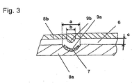
- Fig. 3 is shown schematically the cross section of an injection molding tool. This has a first mold half 8a and overlying a second mold half 8b. Between these mold halves, a molding space 6 is given, which has a gap height c of 1 - 6 mm.
- the first mold half 8a has a recess 9a which is approximately semicircular in cross-section.
- the second mold half 8b has vertically aligned a bulge 9b, which has a complementary shape, but is significantly smaller.
- the recess 9a has a width in the cross section of a, the bulge 9b in cross section has a width of b.
- b is smaller than a depending on c.
- the instrument panel according to the invention has the advantage that it is much more stable than previous instrument panels due to its inherent stability (i.e. It can be connected directly to the front wall and / or the motor vehicle body of a motor vehicle. It is no longer necessary to support the instrument panel according to the invention on a cross member of the motor vehicle.
- a particularly important aspect of the invention is that with a carrier according to the invention in particular increases the stability of the instrument panel is due to the possible omission of a cross member lightweight construction requirements are met.
- Fig. 1a in which the lines running there reflect the flow of power in the instrument panel. It is now possible, for example, to lay strip-shaped fibrous material in these flux lines. At the power flux lines, where special high forces act, then special adjustments can be made (either by more material or by special materials).
- a fiber material As a fiber material, several materials have been found to be particularly preferred. For example, it is possible to insert strips of woven glass fiber mats. These may for example be pre-impregnated with a thermoplastic or even contain thermoplastic threads, eg polypropylene threads, so that the subsequent integration into matrix material is even better (such products are available, for example, from the company "Vetrotex”). The insertion of such strips (or “tailored mats”) with opening areas, so quasi in "mask shape” is particularly suitable when the wearer is also to be heavily loaded on torsion.
- thermoplastic threads eg polypropylene threads
- the fiber material is not a fabric or fleece but a strand of individual fibers, which may also be connected on the body side and thus take over the cross member function.
- the matrix material which forms the plastic plate elements according to the invention which at least partially surround the line-shaped elements, it is preferably a relatively "stable" material, which penetrates the fiber material at least partially and this connection creates an extremely stable, yet lightweight structure.
- the material most likely to be a combination with stable plastics such as polypropylene (eg PP30 with 30 mm long glass fiber reinforced propylene (polypropylene 30 LGF)) unreinforced polyamides possible.
- the tensile modulus of elasticity of the matrix material should preferably be more than 2000 N / m 2 , particularly preferably more than 3500 N / m 2 .
- sandwich structures made of several layers of glass fiber mats with different separating layers are used.
- connection of the fiber material with the matrix material also different connection possibilities are given.
Landscapes
- Engineering & Computer Science (AREA)
- Mechanical Engineering (AREA)
- Chemical & Material Sciences (AREA)
- Manufacturing & Machinery (AREA)
- Composite Materials (AREA)
- Combustion & Propulsion (AREA)
- Transportation (AREA)
- Instrument Panels (AREA)
- Body Structure For Vehicles (AREA)
- Injection Moulding Of Plastics Or The Like (AREA)
- Casting Or Compression Moulding Of Plastics Or The Like (AREA)
- Diaphragms For Electromechanical Transducers (AREA)
Abstract
Description
Die vorliegende Erfindung betrifft ein Verfahren zu Herstellung einer Instrumententafel, sowie ein Kraftfahrzeug enthaltend eine Instrumententafel nach diesem Verfahren hergestellt.The present invention relates to a method for manufacturing an instrument panel, and a motor vehicle comprising an instrument panel produced by this method.
Es sind verschiedene Ausführungsformen von Instrumententafeln für Kraftfahrzeuge bekannt.There are various embodiments of instrument panels for motor vehicles known.
Üblicherweise sind Instrumententafeln z.B. auf einem zwischen den A-Säulen eines Kraftfahrzeuges angeordneten Querträger befestigt. Hierzu weisen die Instrumententafeln selbst meist noch eine zusätzliche Trägerstruktur auf, auf welchem sich eine Hülle aus meist spritzgegossenem Kunststoff abstützt, welche fahrzeuginnenraumseitig mit einer Dekorschicht belegt sein kann.Usually instrument panels are e.g. mounted on a arranged between the A-pillars of a motor vehicle crossmember. For this purpose, the instrument panels themselves usually still have an additional support structure on which a shell of mostly injection-molded plastic is supported, which can be occupied on the vehicle interior side with a decorative layer.
Der Nachteil von diesen bekannten Instrumententafeln liegt darin, dass diese aufgrund ihres oben geschilderten Aufbaus recht gewichtsintensiv sind und trotzdem angesichts der sie angreifenden Lasten stellenweise trotzdem unterdimensioniert oder überdimensioniert sind, so dass es z.B. zu ungewünschten Brüchen der Instrumententafel bei einer Kollision kommen kann. Besonders wesentlich ist allerdings der Gewichtsaspekt, wobei der übliche Querträger außerdem für ein hohes Fahrzeuggewicht sorgt, da er allein z.B. 6 - 8 kg schwer sein kann.The disadvantage of these known instrument panels is that they are due to their above-described Structure are quite weight-intensive and still in view of the attacking loads in places undersized or oversized, so that, for example, may lead to unwanted fractures of the instrument panel in a collision. Particularly important, however, is the weight aspect, the usual cross member also ensures a high vehicle weight, as it alone, for example, can be 6 - 8 kg heavy.
Zur Versteifung der Instrumententafel ist es bisher üblich gewesen, stellenweise flächige Verstärkungen anzubringen, etwa an besonders belasteten Stellen wie Airbagdurchgangsöffnungen etc. Hierdurch ergibt sich allerdings das Problem, dass die Anbindung von z.B. Metallverstärkungsblechen an ein Kunststoffteil relativ aufwendig sein kann. So kann außerdem z.B. durch den unterschiedlichen Wärmeausdehnungskoeffizienten des Metallbleches sowie des daran anliegenden Kunststoffes es zu Verwölbungen in der Instrumententafel kommen, welche fahrerraumseitig sichtbar sind und somit eine Qualitätseinbuße darstellen.For stiffening the instrument panel, it has hitherto been customary to apply surface reinforcements in places, for example at particularly heavily loaded areas such as airbag passage openings etc. However, this results in the problem that the connection of e.g. Metal reinforcing plates can be relatively expensive to a plastic part. Thus, for example, e.g. Due to the different coefficients of thermal expansion of the metal sheet and the adjoining plastic it comes to warping in the instrument panel, which are visible on the driver side, and thus represent a loss of quality.
Der vorliegenden Erfindung liegt daher die Aufgabe zugrunde, ein Verfahren zur Herstellung einer Instrumententafel zu schaffen, welches garantiert, dass einerseits hoch belastbare Instrumententafel gegeben ist und diese außerdem leichtgewichtig, kostengünstig und sicher ist.The present invention is therefore an object of the invention to provide a method for producing an instrument panel, which guarantees that on the one hand highly resilient instrument panel is given and this is also lightweight, inexpensive and safe.
Diese Aufgabe wird durch ein Herstellungsverfahren nach Anspruch 1 gelöst. Das Dokument
Hierbei sind die Rahmenstruktur bzw. die damit stoffschlüssig verbundenen Kunststoffelemente direkt mit einer Dekorschicht belegt, und andererseits ist die kraftaufnehmende Rahmenstruktur der Instrumententafel direkt mit einer Stirnwand und/oder einer Kraftfahrzeugkarosserie verbunden. Die Rahmenstruktur ist hierbei derart ausgelegt, dass ein zwischen den A-Säulen des Kraftfahrzeugs verlaufender Querträger verzichtbar ist.In this case, the frame structure or the materially connected thereto plastic elements are directly covered with a decorative layer, and on the other hand, the force-absorbing frame structure of the instrument panel is directly connected to an end wall and / or a motor vehicle body. The frame structure is in this case designed such that a running between the A-pillars of the motor vehicle cross member is dispensable.
Hierdurch wird ein leicht zu bauender und außerdem kostengünstig herzustellender Träger, der gleichzeitig eine Instrumententafel darstellt, erstmals bereitgestellt.As a result, an easy to build and also inexpensive to produce carrier, which also represents an instrument panel, provided for the first time.
Die Rahmenstruktur wird hierbei so berechnet, dass die auf die Instrumententafel einwirkenden Kräfte hauptsächlich durch deren geeignete Struktur aufgefangen werden. Hierzu tragen selbstverständlich auch die Kunststoffplattenelemente bei, welche auch zu einer Versteifung der Instrumententafel beitragen, da sie in ihren Randbereichen mit den linienförmigen Elementen stoffschlüssig verbunden sind. Unter stoffschlüssiger Verbindung ist hierbei primär ein Umschmelzen bzw. Anschmelzen von flüssigem Kunststoff an die linienförmigen Elemente gemeint. Alternativ sind unter der stoffschlüssigen Verbindung allerdings auch z.B. Schweißverfahren bzw. weitere Verfahren der "chemischen Verschmelzung", etwa mit Kunststoffharzen gemeint. Die Kunststoffplattenelemente werden hierbei in einem Spritzgussverfahren als flüssiger Kunststoff in ein entsprechendes Formwerkzeug eingebracht, in welchem die linienförmigen Elemente bereitgestellt sind.The frame structure is in this case calculated so that the forces acting on the instrument panel are absorbed mainly by their appropriate structure. Of course, also contribute to the plastic plate elements, which also contribute to a stiffening of the instrument panel, as they are materially connected in their edge regions with the line-shaped elements. Under cohesive connection is meant primarily a remelting or melting of liquid plastic to the linear elements. Alternatively, however, by the cohesive connection, for example, welding processes or other processes of "chemical fusion", such as with plastic resins meant. The plastic plate elements are hereby introduced in an injection molding process as a liquid plastic in a corresponding mold, in which the line-shaped elements are provided.
Mit der erfindungsgemäßen Instrumententafel wird somit erstmals eine "ganzheitliche" Verstärkung der gesamten Instrumententafel erreicht, im Gegensatz zu bisher üblichen lediglich lokalen Verstärkungen. Hierbei bietet sich bei der Auslegung der erfindungsgemäßen Rahmenstruktur auch ein besonderes Verfahren an, welches eine auf die Belastung abgestimmte Konstruktion der Instrumententafel ermöglicht.With the instrument panel according to the invention thus for the first time a "holistic" gain of the entire instrument panel is achieved, in contrast to previously usual only local reinforcements. Here, in the design of the frame structure according to the invention also offers a special method, which allows a tuned to the load construction of the instrument panel.
Zunächst wird hierbei der ganze Cockpitbereich als ein "großer Quader" gesehen. Auf diesen Quader werden die Lasten definiert (z.B. "Missbrauchskräfte", wie sie bei der Airbagauslösung bzw. ein "Mantelrichttest" an dem Lenkrad entstehen können). Dann werden außerdem Bereiche definiert, in denen ein Freiraum liegen sollte, also Bereiche, in denen der Quader "ausgeschnitten" sein muss, um z.B. Fußraum für Fahrzeuginsassen zu schaffen. Dort kann sich dann keine Struktur befinden. Bei der dann stattfindenden Auslegung der Profile wird der Hauptkraftfluss im verbleibenden Quader bestimmt. Hieran wird ein angepasstes "Gitterprofil" modelliert. Entlang dieser Gitterlinien werden dann linienförmige Elemente einer Rahmenstruktur angeordnet. Zusätzlich wird in den Bereichen zwischen den linienförmigen Elementen bzw. "Kraftflusslinien" überspannende Bereiche vorgesehen, hier die erfindungsgemäßen Kunststoffplattenelemente. Auf diese Art wird eine optimierte Trägerstruktur erhalten, welche lediglich dort existiert, wo sie aus Kräftegründen wirklich nötig ist. Vorteilhaft hieran ist, dass Verstärkungen sich dann nur dort befinden, wo sie tatsächlich gebraucht werden, durch die optimierte Auslegung Gesamtgewicht des Kraftfahrzeuges eingespart wird, unter Umständen sogar ein Querträger sich einsparen lässt, sich Kosten einsparen lassen und mehr Bauraum zur Verfügung steht. Hierdurch wird mehr nutzbarer Raum im Cockpitbereich erzeugt, z.B. für Klimagerät, Elektronikkomponenten, Ablageboxen; dadurch entsteht ein höherer Gestaltungsspielraum beim Entwurf der Instrumententafel.First, the whole cockpit area is seen as a "big cuboid". On this cuboid, the loads are defined (eg "abuse forces", as they may arise in the airbag deployment or a "jacket direction test" on the steering wheel). Then also areas are defined in which a free space should lie, so areas in which the cuboid must be "cut out", for example, footwell for vehicle occupants to create. There can then be no structure. In the then held interpretation of the profile of the main power flow is determined in the remaining cuboid. An adapted "grid profile" is modeled on this. Line-shaped elements of a frame structure are then arranged along these grid lines. In addition, in the areas between the line-shaped elements or "power lines" spanning areas are provided, here the plastic plate elements according to the invention. In this way, an optimized support structure is obtained, which exists only where it is really necessary from forces forces. The advantage of this is that reinforcements are then only there, where they are actually needed, is saved by the optimized design total weight of the motor vehicle, in some circumstances even a cross member can be saved, can save costs and more space is available. This creates more usable space in the cockpit area, eg for air conditioner, electronic components, storage boxes; This creates a higher degree of design freedom in the design of the instrument panel.
Das erfindungsgemäße Verfahren ist ein Verfahren zum Herstellen einer Instrumententafel und Anbringen derselben in einem Kraftfahrzeug, wobei eine aus linienförmigen Elementen aufgebaute Rahmenstruktur, welche bereichsweise mit Kunststoffplattenelementen verschlossen ist, mit einer Dekorschicht belegt wird, wobei die Rahmenstruktur derart ausgelegt ist, dass ein zwischen den A-Säulen des Kraftfahrzeugs verlaufender Querträger verzichtbar ist und die Rahmenstruktur direkt mit einer Stirnwand und/oder der Kraftfahrzeugkarosserie verbunden wird.The inventive method is a method for producing an instrument panel and attaching the same in a motor vehicle, wherein a built-up of linear elements frame structure, which is partially closed with plastic plate elements is covered with a decorative layer, wherein the frame structure is designed such that a between the A -Columns of the motor vehicle extending cross member is dispensable and the frame structure is connected directly to an end wall and / or the vehicle body.
Eine vorteilhafte Weiterbildung der Instrumententafel sieht vor, dass der Querschnitt der linienförmigen Elemente im in der Instrumententafel verbauten Zustand U-förmig, rund, oval oder mehreckig ist. Es können hier prinzipielle geschlossene oder offene Querschnitte zur Anwendung kommen. Es ist hierbei zu beachten, dass die linienförmigen Elemente im verbauten Zustand auch zur Führung von Kabeln bzw. zur Luftführung dienen können. Insbesondere vorteilhaft ist z.B. ein U-Profil, welches zur Außenseite der Instrumententafel hin offen ist, so dass z.B. Kabelstränge von außen leicht zugänglich in dieses U-Profil eingelegt werden können.An advantageous development of the instrument panel provides that the cross section of the linear elements in the installed state in the instrument panel is U-shaped, round, oval or polygonal. Principally closed or open cross-sections can be used here. It should be noted here that the linear elements in the installed state can also serve to guide cables or to guide the air. Particularly advantageous is, for example, a U-profile, which is open to the outside of the instrument panel, so that, for example, cable harnesses can be easily accessed from outside in this U-profile.
Neben Profilen mit einfachen (Endlos-)Querschnittsformen sind auch kompliziertere Strukturen verwendbar, wenn spezielle Aufgabenbereiche erfüllt werden sollen. So ist es z.B. möglich, dass das linienförmige Element ein Streifen einer Bienenwabensandwichstruktur ist. Hierbei werden z.B. mehrere nebeneinander liegende Bienenwaben-Achtecken vorgesehen, welche zwischen zwei Deckplatten eingeschlossen sind. Somit ergibt sich eine sehr leicht bauende Struktur mit sehr guten Festigkeitswerten.In addition to profiles with simple (endless) cross-sectional shapes, more complicated structures can also be used if special task areas are to be fulfilled. So it is e.g. possible that the line-shaped element is a strip of honeycomb sandwich structure. Here, e.g. several adjacent honeycomb octagons provided, which are enclosed between two cover plates. This results in a very easy-to-build structure with very good strength values.
Eine besondere Art, die Anbindung des angespritzten, angeschmolzenen oder umspritzten Kunststoffes an die linienförmigen Elemente zu erreichen, ist z.B., dass die linienförmigen Elemente an ihrer Außenseite spezielle Stege aufweisen. Diese dienen zunächst einmal der Versteifung des linienförmigen Elementes selbst, es ist aber hierdurch auch eine Vergrößerung der Ankoppelfläche an den zu umspritzenden Kunststoff gegeben. Es hat sich gezeigt, dass aus Stabilitätsgründen es besonders günstig ist, die Stege jeweils geneigt (z.B. 45°) zur Hauptverlaufsrichtung des linienförmigen Elementes selbst anzuordnen, um so eine höchstmögliche Stabilität und Einbindung des linienförmigen Elementes in die Instrumententafel zu erreichen.One particular way of achieving the connection of the molded, melted or overmoulded plastic to the linear elements is, for example, that the line-shaped elements have special webs on their outside. These are initially used to stiffen the linear element itself, but it is thereby given an increase in the coupling surface of the plastic to be encapsulated. It has been found that for reasons of stability it is particularly favorable to arrange the webs in each case inclined (for example 45 °) to the main course direction of the linear element itself in order to achieve the highest possible stability and integration of the linear element in the instrument panel.
Als Materialien für die linienförmigen Elemente kommen vielfältige Materialien in Betracht. Zunächst können die linienförmigen Elemente aus Metallblech, etwa Stahlblech, gelochtem Metallblech oder z.B. aus Aluminium oder Magnesium bestehen. Selbstverständlich ist es aber auch möglich, Fasermaterialien vorzusehen. Es können hierbei prinzipiell streifenförmige Gewebe bzw. Gewirke eingesetzt werden, welche erst im Umspritzungsvorgang ihre volle Festigkeit entfalten. Es ist auch möglich, dass die linienförmigen Elemente aus Endlosfasern verbaut werden. Dies sind z.B. Rohre aus Endlosfasern, als Grundfasern kommen hier Glasfasern oder auch Kohlefasern zur Anwendung, welche z.B. bereits vor dem Verspritzen mit einem thermoplastischen Kunststoff gebunden sind. Durch das anschließende Umspritzen mit dem Kunststoff, welche die späteren Kunststoffplattenelemente bildet, ergibt sich eine besonders gute Verschmelzung dieser linienförmigen Elemente in der Gesamtstruktur.As materials for the linear elements come diverse materials into consideration. First, the line-shaped elements made of sheet metal, such as sheet steel, perforated metal sheet or eg made of aluminum or magnesium. Of course, it is also possible to provide fiber materials. In principle, strip-shaped woven fabrics or knitted fabrics can be used, which unfold their full strength only in the encapsulation process. It is also possible that the linear elements be made of continuous fibers. These are, for example, tubes made of continuous fibers, as base fibers here glass fibers or carbon fibers are used, which are already bound for example before spraying with a thermoplastic material. The subsequent encapsulation with the plastic, which forms the later plastic plate elements, results in a particularly good fusion of these linear elements in the forest.
Die Kunststoffplattenelemente können aus verschiedenen Kunststoffen gebildet sein. Z.B. ist es möglich, dass diese aus einem thermoplastischen Kunststoff gebildet sind, z.B. aus PP30LGF, einem Polypropylen-Werkstoff, welcher Langfaseranteile besitzt. Diese Langfaserteile sind Glasfasern, beim erfindungsgemäßen Spritzgussverfahren haben diese Glasfasern vorzugsweise eine Länge von 10 mm. Alternative Kunststoffe hierzu sind z.B. Polyamide PA, ABS, PC, ABS/PC, Polyinide, PEEK, PEU, PPS, PEI, PSU, PESU, PPSU und PTFE.The plastic plate elements may be formed of different plastics. For example, it is possible that these are made of a thermoplastic material, e.g. made of PP30LGF, a polypropylene material with long fiber content. These long fiber parts are glass fibers, in the injection molding process according to the invention, these glass fibers preferably have a length of 10 mm. Alternative plastics for this purpose are e.g. Polyamides PA, ABS, PC, ABS / PC, polyimides, PEEK, PEU, PPS, PEI, PSU, PESU, PPSU and PTFE.
Die erfindungsgemäße Instrumententafel hat den Vorteil, dass sie einen "ganzheitlichen" Ansatz bei der Stabilität der Instrumententafel verfolgt. Es werden keine lediglich lokalen Verstärkungen eingebracht, sondern die Gesamtstruktur hat die angestrebte Steifigkeit. Der erfindungsgemäß gebildete Träger kann zusätzlich, wenn dies aus ästhetischen Gründen gewünscht wird, mit einer zu dem Kraftfahrzeuginnenraum hin angeordneten Dekorschicht belegt sein. Dies kann z.B. eine Slush-Haut, Leder oder auch ein Kunststoffgewebe, Textil, Gießhaut, Sprühhaut sein. Vorteilhaft hierbei ist auf jeden Fall, im Gegensatz zu bekannten Konzepten, dass die Dekorschicht direkt auf eine tragende Struktur geklebt werden kann, es sind keine zusätzlichen Bauelemente, wie etwa Querverstrebungen zwischen einem Querträger eines Kraftfahrzeuges und einer tragenden Kunststoffhaut für die Dekorschicht nötig.The instrument panel according to the invention has the advantage that it pursues a "holistic" approach to the stability of the instrument panel. There are no purely local reinforcements introduced, but the overall structure has the desired stiffness. In addition, if desired for aesthetic reasons, the carrier formed according to the invention can be covered with a decorative layer arranged towards the motor vehicle interior. This can be, for example, a slush skin, leather or else a synthetic fabric, textile, cast skin, spray skin. Advantageous this is in any case, in contrast to known concepts, that the decorative layer can be glued directly onto a supporting structure, there are no additional components, such as cross bracing between a cross member of a motor vehicle and a supporting plastic skin for the decorative layer necessary.
Das erfindungsgemäße Verfahren zur Herstellung einer Instrumententafel hat verschiedene vorteilhafte Ausgestaltungen.The inventive method for producing an instrument panel has various advantageous embodiments.
So ist es z.B. möglich, dass die linienförmigen Elemente als vorher praktisch vollständiger Rahmen in das Formwerkzeug eingelegt werden. Dies ist z.B. möglich, wenn ein vorgefertigter Metallrahmen in ein Formwerkzeug eingelegt wird.So it is e.g. possible that the line-shaped elements are inserted as previously practically complete frame in the mold. This is e.g. possible if a prefabricated metal frame is inserted into a mold.
In Bezug auf die Herstellungskosten ist es vorteilhaft, dass die linienförmigen Elemente jedoch als Einzelstücke in das Formwerkzeug eingelegt werden. Hierzu können z.B. von einem Endlosmaterial (z.B. einem Rohr aus Fasermaterialien) Stücke abgetrennt werden, welche dann einzeln in das Formwerkzeug eingelegt werden und erst beim Umspritzen mit dem in das Formwerkzeug eingespritzten Kunststoff einen fertigen Rahmen bilden.With regard to the production costs, it is advantageous that the linear elements are inserted as individual pieces in the mold. For this, e.g. pieces are separated from an endless material (for example a tube made of fibrous materials), which pieces are then placed individually in the mold and form a finished frame only when they are overmoulded with the plastic injected into the mold.
Eine besonders vorteilhafte Weiterbildung sieht vor, dass Streifen aus einem Fasermaterial, etwa einem Gewebe, einem Vlies oder dergleichen, in eine Vertiefung einer ersten Formhälfte eines Spritzgusswerkzeuges eingelegt werden und anschließend eine zweiten Formhälfte, welche eine zur Vertiefung korrespondierende Auswölbung aufweist, mit der ersten Formhälfte so in Deckung gebracht wird, dass zwischen beiden zumindest bereichsweise ein Spalt verbleibt und anschließend ein Kunststoff in den Formraum eingespritzt wird. Hierbei wird der Streifen aus Fasermaterial durch das Formwerkzeug selbst (also durch die Vertiefung bzw. die Auswölbung der Formhälften) in die richtige Form gebracht und danach umspritzt. Es ergibt sich hierdurch eine sehr kostengünstige Anordnung, welche stabile Querschnitte der linienförmigen Elemente ermöglicht. Zum besseren Fließen des Kunststoffes im Bereich des eingelegten Streifens ist es vorteilhaft, dass zwischen den korrespondierenden Vertiefungen bzw. Auswölbungen zusätzlich zur Dicke des Streifens nochmals z.B. 2 - 4 mm große Spalträume vorgesehen werden. Die Temperatur des Werkzeuges (also der Formhälften) liegt hierbei etwa auf Höhe der Erweichungstemperatur des zu verspritzenden Kunststoffes, also z.B. ca. 160°C bei Polypropylen.A particularly advantageous development provides that strips of a fiber material, such as a fabric, a nonwoven or the like, are inserted into a recess of a first mold half of an injection mold and then a second mold half, which has a corresponding recess for bulge, with the first mold half so it is brought into coincidence that between the two at least partially a gap remains and then a plastic is injected into the mold cavity. Here, the strip of fiber material by the mold itself (ie by the recess or the bulge of the mold halves) is brought into the correct shape and then encapsulated. This results in a very cost-effective arrangement, which allows stable cross sections of the linear elements. For better flow of the plastic in the region of the inserted strip, it is advantageous that in addition to the thickness of the strip, for example, 2 - 4 mm large gaps are provided between the corresponding recesses or bulges. The temperature of the tool (ie the mold halves) in this case is approximately equal to the softening temperature of the plastic to be sprayed, so for example about 160 ° C in polypropylene.
Die hier gezeigte Erfindung ist insbesondere für Kraftfahrzeuge anwendbar. Es bietet sich hierbei an, dass die kraftaufnehmende Rahmenstruktur der Instrumententafel direkt mit einer Stirnwand und/oder der Kraftfahrzeugkarosserie verbunden ist. Es muss keine Verbindung zu einem Querträger hergestellt werden, um die Instrumententafel abzustützen. Es kann sogar durch entsprechend starke Auslegung der Rahmenstruktur erreicht werden, dass auf den Querträger verzichtet werden kann und somit weiteres Gewicht gespart wird.The invention shown here is particularly applicable to motor vehicles. It makes sense in this case that the force-absorbing frame structure of the instrument panel is connected directly to an end wall and / or the motor vehicle body. There is no need to connect to a cross member to support the instrument panel. It can even be achieved by a correspondingly strong interpretation of the frame structure that waives the cross member can be and thus further weight saved.
Die Rahmenstruktur könnte zur Luftführung oder Kabelführung dienen. Ebenfalls wäre es denkbar, die Rahmenstruktur als Verteiler der Luft in großflächiger Ausströmfelder zu nutzen (s.
Weitere vorteilhafte Weiterbildungen werden in den übrigen abhängigen Ansprüchen angegeben.Further advantageous developments are specified in the remaining dependent claims.
Die Erfindung wird nun anhand mehrerer Figuren erläutert. Es zeigen:
- Fig. 1a
- eine erfindungsgemäße Rahmenstruktur,
- Fig. 1b
- eine erfindungsgemäße Instrumententafel,
- Fig. 1c
- einen Schnitt gem. Schnittebene A aus
Fig. 1b , - Fig. 1d
- eine zur Luftführung dienende Rahmenstruktur mit flächigen Ausströmfeldern im Bereich der Kunststoffplattenelemente,
- Fign. 2a - 2d
- verschiedene Ausführungsbeispiele von linienförmigen Elementen im Querschnitt und in der Seitenansicht sowie
- Fig. 3
- einen Querschnitt durch ein erfindungsgemäßes Spritzgusswerkzeug zur Herstellung einer erfindungsgemäßen Instrumententafel.
- Fig. 1a
- a frame structure according to the invention,
- Fig. 1b
- an instrument panel according to the invention,
- Fig. 1c
- a cut acc. Section plane A off
Fig. 1b . - Fig. 1d
- a frame structure serving for air guidance with two-dimensional discharge fields in the area of the plastic plate elements,
- FIGS. 2a - 2d
- Various embodiments of line-shaped elements in cross-section and in the side view and
- Fig. 3
- a cross section through an inventive injection molding tool for producing an instrument panel according to the invention.
In
Die in
Die linienförmigen Elemente 2 sind bei der Ausführungsform nach
Dies wird durch den in
In
In
In
Schließlich zeigt
Die Herstellung der Instrumententafel nach er Erfindung ist auf verschiedene Weisen möglich. Besonders einfach ist es hierzu, dass linienförmige Elemente in einen Formraum eines Spritzgusswerkzeuges eingelegt werden und anschließend in dem Spritzgusswerkzeug, unter Bildung der Instrumententafel, mit Kunststoff zumindest bereichsweise umschmolzen werden. Hierbei sieht eine Variante vor, dass die linienförmigen Elemente als vorher fertiger selbsttragender Rahmen (welche etwa aussähen, wie der Rahmen in
Es kann jedoch sehr kostengünstig sein, dass die linienförmigen Elemente als Einzelstücke in den Formraum eingelegt werden. Hierzu ist eine besonders vorteilhafte Herstellvariante vorgesehen, welche in
In
Die erste Formhälfte 8a hat eine im Querschnitt etwa halbkreisförmige Vertiefung 9a. Die zweite Formhälfte 8b hat vertikal fluchtend eine Auswölbung 9b, welche eine komplementäre Form besitzt, allerdings deutlich kleiner ist. Die Vertiefung 9a hat eine Breite im Querschnitt von a, die Auswölbung 9b im Querschnitt eine Breite von b. b ist in Abhängigkeit von c kleiner als a.The
Nun ist es möglich, einen aus einem Fasergeflecht (Fasergewebe/Faservlies) bestehenden Streifen 7 entlang der Vertiefung 9a zu legen, so dass dieser im wesentlichen den halbkreisförmigen Querschnitt der Vertiefung 9a annimmt. Daraufhin wird dann die zweite Formhälfte 8b bis auf den Mindestspalt c heruntergefahren. Hiernach kommt es zu einem Spritzguss eines thermoplastischen Kunststoffes in dem Formraum 6, wobei der Streifen 7 getränkt und außerdem in dem Formraum 6 Kunststoffplattenelemente 5 sich bilden. Hierdurch ist auf eine sehr kostengünstige Weise eine erfindungsgemäße Instrumententafel herstellbar.It is now possible to lay a strip 7 consisting of a fibrous web (fibrous web / non-woven fabric) along the
Die erfindungsgemäße Instrumententafel hat den Vorteil, dass sie aufgrund ihrer Eigenstabilität (d.h. wegen der Rahmenstruktur) deutlich stabiler ist als bisherige Instrumententafeln. Sie kann direkt mit der Stirnwand und/oder der Kraftfahrzeugkarosserie eines Kraftfahrzeuges verbunden sein. Es ist nicht mehr nötig, die erfindungsgemäße Instrumententafel auf einem Querträger des Kraftfahrzeuges abzustützen.The instrument panel according to the invention has the advantage that it is much more stable than previous instrument panels due to its inherent stability (i.e. It can be connected directly to the front wall and / or the motor vehicle body of a motor vehicle. It is no longer necessary to support the instrument panel according to the invention on a cross member of the motor vehicle.
Im Folgenden sollen nochmals besonders wichtige Punkte der Erfindung einzeln betont werden.In the following, again particularly important points of the invention will be emphasized individually.
Es ist besonders vorteilhaft, dass mit der vorliegenden Konstruktion die Integrierung von linienförmigen Elementen in Form von Hohlprofilen möglich ist, so dass innen verlaufende Hohlräume der Profile auch zur Führung von z.B. Kabeln oder auch Luftströmen zur Innenraumbelüftung genutzt werden können. So wird nochmals insbesondere auf die
Ein besonders wichtiger Aspekt der Erfindung geht dahin, dass mit einem erfindungsgemäßen Träger insbesondere die Stabilität der Instrumententafel erhöht wird, durch den möglichen Verzicht auf einen Querträger werden Leichtbauanforderungen erfüllt.A particularly important aspect of the invention is that with a carrier according to the invention in particular increases the stability of the instrument panel is due to the possible omission of a cross member lightweight construction requirements are met.
Dies wird vorzugsweise dadurch erreicht, dass als linienförmige Elemente, z.B. Bündel von Endlosfasern oder Streifen von Mattenmaterial eingelegt werden, wobei das Mattenmaterial als ein- oder mehrschichtig aufgebautes Vlies oder Gewebe ausgestaltet ist. Dem liegt der erfindungsgemäße Gedanke zugrunde, dass es kostenaufwendig und auch gewichtsintensiv ist, eine stabile Instrumententafel überall gleich stark zu gestalten, um so auf jeden Fall auch an der am stärksten belasteten Stelle ausreichende Stabilität zu besitzen.This is preferably achieved by using as line-shaped elements, e.g. Bundles of continuous fibers or strips of mat material are inserted, wherein the mat material is configured as a single or multi-layer constructed non-woven or fabric. This is based on the idea according to the invention that it is costly and also weight-intensive to make a stable instrument panel the same everywhere, so as to have sufficient stability in any case, even at the most heavily loaded point.
In diesem Zusammenhang wird rückblickend nochmals auf die
Als Fasermaterial haben sich mehrere Materialien als besonders vorzugsweise herausgestellt. So ist es z.B. möglich, Streifen aus gewebten Glasfasermatten einzulegen. Diese können z.B. mit einem Thermoplasten vorimprägniert sein oder sogar Thermoplast-Fäden, z.B. Polypropylen-Fäden enthalten, so dass die anschließende Einbindung in Matrixmaterial noch besser erfolgt (solche Produkte sind z.B. bei der Firma "Vetrotex" erhältlich). Das Einlegen solcher Streifen (bzw. "zugeschnittener Matten") mit Öffnungsbereichen, also quasi in "Maskenform" bietet sich insbesondere an, wenn der Träger auch stark auf Torsion belastet werden soll.As a fiber material, several materials have been found to be particularly preferred. For example, it is possible to insert strips of woven glass fiber mats. These may for example be pre-impregnated with a thermoplastic or even contain thermoplastic threads, eg polypropylene threads, so that the subsequent integration into matrix material is even better (such products are available, for example, from the company "Vetrotex"). The insertion of such strips (or "tailored mats") with opening areas, so quasi in "mask shape" is particularly suitable when the wearer is also to be heavily loaded on torsion.
Insbesondere zur Aufnahme von Zugbelastung (z.B. bei der Ersetzung eines Querträgers) kann es auch möglich sein, Glas in Endlos-Glasfasern vorzusehen bzw. ganze Bündel von Endlos-Glasfasern. Hier ist das Fasermaterial kein Gewebe bzw. Vlies sondern ein Strang einzelner Fasern, welche eventuell auch karosserieseitig angebunden werden können und somit die Querträgerfunktion übernehmen.In particular, to absorb tensile load (e.g., in the replacement of a cross member), it may also be possible to provide glass in continuous glass fibers or whole bundles of continuous glass fibers. Here, the fiber material is not a fabric or fleece but a strand of individual fibers, which may also be connected on the body side and thus take over the cross member function.
Insbesondere ist also vorteilhaft, dass hier (je nach Belastung) die Wahl des Materials bzw. wie viel von diesem Material verbaut wird, getroffen werden kann.In particular, it is therefore advantageous that the choice of material or how much of this material is installed can be made here (depending on the load).
Hierzu sollen noch einige Beispiele genannt werden. Bei dem Matrixmaterial, welches die erfindungsgemäßen Kunststoffplattenelemente bildet, welche die linienförmigen Elemente zumindest teilweise umschließen, handelt es sich vorzugsweise um ein relativ "stabiles" Material, welches das Fasermaterial zumindest bereichsweise durchdringt und durch diese Verbindung eine extrem stabile aber trotzdem leichtgewichtige Struktur entstehen lässt. Es ist hier im Allgemeinen nicht ausreichend, das Material einfach nur "einzuschäumen", am ehesten ist eine Verbindung mit stabilen Kunststoffen wie Polypropylen (z.B. PP30 mit 30 mm langen Glasfasern verstärktes Propylen (Polypropylen 30 LGF)) möglich, alternativ sind z.B. auch verstärkte oder unverstärkte Polyamide möglich. Hierbei sollte der Zug-E-Modul des Matrixmaterials vorzugsweise mehr als 2000 N/m2, besonders vorzugsweise über 3500 N/m2 betragen. Für besonders extreme Anwendungen ist allerdings auch möglich, Material mit E-Modulen von 22000 N/m2 und größer zu erreichen, hier kommen z.B. Sandwich-Aufbauten aus mehreren Schichten Glasfasermatten mit unterschiedlichen Trennschichten zum Einsatz.Here are some examples to be mentioned. In the matrix material which forms the plastic plate elements according to the invention, which at least partially surround the line-shaped elements, it is preferably a relatively "stable" material, which penetrates the fiber material at least partially and this connection creates an extremely stable, yet lightweight structure. In general, it is not sufficient to "foam" the material, most likely to be a combination with stable plastics such as polypropylene (eg PP30 with 30 mm long glass fiber reinforced propylene (polypropylene 30 LGF)) unreinforced polyamides possible. In this case, the tensile modulus of elasticity of the matrix material should preferably be more than 2000 N / m 2 , particularly preferably more than 3500 N / m 2 . However, for very extreme applications it is also possible to achieve material with moduli of 22000 N / m 2 and larger, come here For example, sandwich structures made of several layers of glass fiber mats with different separating layers are used.
Bei der Verbindung des Fasermaterials mit dem Matrixmaterial sind auch unterschiedliche Verbindungsmöglichkeiten gegeben.In the connection of the fiber material with the matrix material also different connection possibilities are given.
Bei nicht so hoch belasteten Teilen kann es z.B. ausreichend sein, in eine Form (wie sie z.B. in
Claims (8)
- A method for the production of a dashboard (1) and attachment thereof in a motor vehicle, with a frame structure (3) constructed from linear elements (2), which is closed in regions with plastics-material plate elements (5), being covered with a decorative layer, the frame structure being designed such that a cross member extending between the A-pillars of the motor vehicle is dispensed with and the frame structure is connected directly to an end wall and/or the motor vehicle body, characterised in that a material-locked connection between the plastics-material plate elements (5) and the linear elements (2) is achieved by injecting in a thermoplastic plastics material which after curing forms the plastics-material plate elements, and melting-round of the thermoplastic plastics material on the linear elements occurs.
- A motor vehicle, containing a dashboard (1) produced according to Claim 1, the force-absorbing frame structure of the dashboard being connected directly to an end wall and/or a motor vehicle body.
- A motor vehicle containing a dashboard according to Claim 2, characterised in that the cross-section of the linear elements in the state installed in the dashboard is U-shaped, round, oval or polygonal.
- A motor vehicle containing a dashboard according to Claim 2, characterised in that the linear element is a strip of a honeycomb sandwich structure.
- A motor vehicle containing a dashboard according to one of Claims 2 to 4, characterised in that the linear element (2) consists of metal sheet, perforated metal sheet, plastics material or of a fibre material.
- A motor vehicle containing a dashboard according to one of Claims 2 to 5, characterised in that the linear element (2) has bars (2') on its outside.
- A motor vehicle containing a dashboard according to one of Claims 2 to 6, characterised in that the dashboard (1) is covered substantially over its full surface with a decorative layer on its upper side.
- A motor vehicle containing a dashboard according to one of Claims 2 to 7, characterised in that the decorative layer is glued directly to the supporting structure.
Applications Claiming Priority (2)
| Application Number | Priority Date | Filing Date | Title |
|---|---|---|---|
| DE10257161A DE10257161A1 (en) | 2002-12-02 | 2002-12-02 | Instrument panel and process for its manufacture |
| EP03780094A EP1567385B1 (en) | 2002-12-02 | 2003-12-01 | Control panel and method for the production thereof |
Related Parent Applications (2)
| Application Number | Title | Priority Date | Filing Date |
|---|---|---|---|
| EP03780094A Division EP1567385B1 (en) | 2002-12-02 | 2003-12-01 | Control panel and method for the production thereof |
| EP03780094.3 Division | 2003-12-01 |
Publications (3)
| Publication Number | Publication Date |
|---|---|
| EP1925488A2 EP1925488A2 (en) | 2008-05-28 |
| EP1925488A3 EP1925488A3 (en) | 2008-06-18 |
| EP1925488B1 true EP1925488B1 (en) | 2011-02-16 |
Family
ID=32318993
Family Applications (2)
| Application Number | Title | Priority Date | Filing Date |
|---|---|---|---|
| EP07076096A Expired - Lifetime EP1925488B1 (en) | 2002-12-02 | 2003-12-01 | Instrument panel and method for its manufacture |
| EP03780094A Expired - Lifetime EP1567385B1 (en) | 2002-12-02 | 2003-12-01 | Control panel and method for the production thereof |
Family Applications After (1)
| Application Number | Title | Priority Date | Filing Date |
|---|---|---|---|
| EP03780094A Expired - Lifetime EP1567385B1 (en) | 2002-12-02 | 2003-12-01 | Control panel and method for the production thereof |
Country Status (10)
| Country | Link |
|---|---|
| US (1) | US20060145506A1 (en) |
| EP (2) | EP1925488B1 (en) |
| JP (1) | JP2006507982A (en) |
| CN (1) | CN100491152C (en) |
| AT (2) | ATE498508T1 (en) |
| AU (1) | AU2003288206A1 (en) |
| DE (4) | DE10257161A1 (en) |
| ES (1) | ES2357973T3 (en) |
| MX (1) | MXPA05005789A (en) |
| WO (1) | WO2004050409A1 (en) |
Families Citing this family (16)
| Publication number | Priority date | Publication date | Assignee | Title |
|---|---|---|---|---|
| DE102005039125B3 (en) * | 2005-08-15 | 2006-09-21 | Faurecia Innenraum Systeme Gmbh | Instrument panel arrangement for use in motor vehicle, has instrument panel having one part displaceable into internal space of motor vehicle relative to instrument panel support by using actuators |
| US20070228762A1 (en) * | 2006-04-03 | 2007-10-04 | Visteon Global Technologies, Inc. | Instrument panel with exposed support structure and method of formation |
| FR2902369B1 (en) * | 2006-06-16 | 2011-05-06 | Faurecia Interieur Ind | FORCED VENTILATION SYSTEM FOR THE CABIN OF A MOTOR VEHICLE, AND CORRESPONDING BOARDBOARD. |
| US7798548B2 (en) * | 2007-01-03 | 2010-09-21 | Gm Global Technology Operations, Inc. | Soft composite trim panel for a vehicle interior |
| DE102008006936A1 (en) | 2007-07-26 | 2009-02-05 | Faurecia Innenraum Systeme Gmbh | Integrated center reinforcement |
| DE102009006960A1 (en) | 2009-01-31 | 2010-08-05 | Aksys Gmbh | Plastic-metal hybrid vehicle-dashboard-assembly support for motor vehicle, has cross member determined for absorbing side impact forces, where support is made from support structure and cross member by pressing and/or injection molding |
| US20110027607A1 (en) * | 2009-07-30 | 2011-02-03 | Magna Seating Inc. | Magnesium hybrid parts and processes |
| DE102010021123B4 (en) | 2010-05-21 | 2016-08-18 | International Automotive Components Group Gmbh | Mold part and method for producing a molded part, in particular a molded part for a motor vehicle, such as a dashboard or a center console |
| JP4918153B2 (en) * | 2010-07-02 | 2012-04-18 | 本田技研工業株式会社 | Body front structure |
| DE102011007668B4 (en) * | 2011-04-19 | 2019-04-25 | Shanghai Yanfeng Jinqiao Automotive Trim Systems Co., Ltd. | Instrument panel for a vehicle |
| GB2521370A (en) * | 2013-12-17 | 2015-06-24 | Prodrive Composites Ltd | A product and a method of making a product |
| DE102015226019A1 (en) * | 2015-12-18 | 2017-06-22 | Sitech Sitztechnik Gmbh | Fiber composite component and method for producing a fiber composite component |
| US11440283B2 (en) * | 2018-02-02 | 2022-09-13 | The Boeing Company | Composite sandwich panels with over-crushed edge regions |
| DE102018128404A1 (en) | 2018-11-13 | 2020-05-14 | Bayerische Motoren Werke Aktiengesellschaft | Bulkhead module |
| DE102018133306A1 (en) * | 2018-12-21 | 2020-06-25 | Bayerische Motoren Werke Aktiengesellschaft | Motor vehicle component with light function |
| DE102019216518B3 (en) * | 2019-10-25 | 2021-03-25 | Magna Exteriors Gmbh | Vehicle door and its method for producing a vehicle door |
Family Cites Families (21)
| Publication number | Priority date | Publication date | Assignee | Title |
|---|---|---|---|---|
| US3141811A (en) * | 1958-04-01 | 1964-07-21 | Johns Manville Fiber Glass Inc | Fibrous laminate and method of producing the same |
| US3042137A (en) * | 1959-09-09 | 1962-07-03 | Gen Motors Corp | Vehicle instrument and dashboard assemblies |
| US3130807A (en) * | 1962-07-05 | 1964-04-28 | Bobby R Mchenry | Air cushion dashboard for automobiles and the like |
| JPS5113298B2 (en) * | 1971-10-20 | 1976-04-27 | ||
| DE3012007A1 (en) | 1980-03-28 | 1981-10-08 | Gebr. Happich Gmbh, 5600 Wuppertal | FOAM BODY, IN PARTICULAR DASHBOARD FOR MOTOR VEHICLES |
| DE3016199A1 (en) * | 1980-04-26 | 1981-11-05 | Fa. Carl Freudenberg, 6940 Weinheim | DASHBOARD FOR MOTOR VEHICLES |
| DE3611486C2 (en) * | 1986-04-05 | 1994-04-21 | Audi Ag | Dashboard for motor vehicles |
| US5273597A (en) | 1988-11-26 | 1993-12-28 | Honda Giken Kogyo Kabushiki Kaisha | Trim member for motor vehicle and method of and system for manufacturing the same |
| US5333901A (en) * | 1993-04-26 | 1994-08-02 | General Motors Corporation | Air bag deployable instrument panel cover |
| US5487800A (en) * | 1994-01-24 | 1996-01-30 | Davidson Textron Inc. | Method of making a covered article by vacuum drawing |
| GB9423776D0 (en) * | 1994-11-25 | 1995-01-11 | Acg Deutschland Gmbh | Dashboard assembly |
| US5564515A (en) * | 1995-08-23 | 1996-10-15 | Chrysler Corporation | Instrument panel assembly |
| FR2746695B1 (en) * | 1996-03-29 | 1998-05-15 | Valeo Climatisation | METHOD OF MANUFACTURING A VEHICLE DASHBOARD, WITH INTEGRATED AIR DUCTS, AND DASHBOARD THUS OBTAINED |
| US5762395A (en) * | 1996-06-25 | 1998-06-09 | General Motors Corporation | Molded cross car support structure |
| JP2001018033A (en) * | 1999-07-01 | 2001-01-23 | Daido Steel Co Ltd | Manufacturing method of precision casting mold |
| US6354623B1 (en) * | 2000-08-03 | 2002-03-12 | Textron Automotive Company Inc. | Automotive trim panel |
| PT1350711E (en) * | 2002-03-27 | 2006-12-29 | Denso Thermal Systems Spa | Hybrid support structure for a vehicle dashboard and method for manufacturing the same |
| US6621688B1 (en) * | 2002-06-26 | 2003-09-16 | Alcoa Fujikura Limited | Electrical distribution system having integral junction box for instrument panel application |
| DE10251761A1 (en) * | 2002-11-05 | 2004-05-19 | Behr Gmbh & Co. | Cross-member forming part of hybrid structure frame for road vehicle has foundation body with U-section groove detouring round centrally mounted heater or air conditioner and holding air duct |
| US20040256878A1 (en) * | 2003-06-20 | 2004-12-23 | Jsp Licenses, Inc. | Fragmentation-resistant instrument panel and method of making same |
| US20050183897A1 (en) * | 2004-02-24 | 2005-08-25 | Lear Corporation | Two-shot co-injected automotive interior trim assembly and method |
-
2002
- 2002-12-02 DE DE10257161A patent/DE10257161A1/en not_active Ceased
-
2003
- 2003-12-01 MX MXPA05005789A patent/MXPA05005789A/en active IP Right Grant
- 2003-12-01 ES ES07076096T patent/ES2357973T3/en not_active Expired - Lifetime
- 2003-12-01 AU AU2003288206A patent/AU2003288206A1/en not_active Abandoned
- 2003-12-01 AT AT07076096T patent/ATE498508T1/en active
- 2003-12-01 EP EP07076096A patent/EP1925488B1/en not_active Expired - Lifetime
- 2003-12-01 CN CNB2003801048794A patent/CN100491152C/en not_active Expired - Fee Related
- 2003-12-01 EP EP03780094A patent/EP1567385B1/en not_active Expired - Lifetime
- 2003-12-01 DE DE20321578U patent/DE20321578U1/en not_active Expired - Lifetime
- 2003-12-01 JP JP2004556248A patent/JP2006507982A/en active Pending
- 2003-12-01 DE DE50313482T patent/DE50313482D1/en not_active Expired - Lifetime
- 2003-12-01 DE DE50310175T patent/DE50310175D1/en not_active Expired - Lifetime
- 2003-12-01 AT AT03780094T patent/ATE401212T1/en not_active IP Right Cessation
- 2003-12-01 US US10/537,111 patent/US20060145506A1/en not_active Abandoned
- 2003-12-01 WO PCT/EP2003/013509 patent/WO2004050409A1/en not_active Ceased
Also Published As
| Publication number | Publication date |
|---|---|
| DE50310175D1 (en) | 2008-08-28 |
| EP1567385A1 (en) | 2005-08-31 |
| DE50313482D1 (en) | 2011-03-31 |
| US20060145506A1 (en) | 2006-07-06 |
| DE10257161A1 (en) | 2004-06-17 |
| EP1925488A3 (en) | 2008-06-18 |
| ES2357973T3 (en) | 2011-05-04 |
| CN100491152C (en) | 2009-05-27 |
| ATE401212T1 (en) | 2008-08-15 |
| EP1567385B1 (en) | 2008-07-16 |
| JP2006507982A (en) | 2006-03-09 |
| MXPA05005789A (en) | 2005-10-18 |
| DE20321578U1 (en) | 2008-03-06 |
| WO2004050409A1 (en) | 2004-06-17 |
| CN1720154A (en) | 2006-01-11 |
| EP1925488A2 (en) | 2008-05-28 |
| ATE498508T1 (en) | 2011-03-15 |
| AU2003288206A1 (en) | 2004-06-23 |
Similar Documents
| Publication | Publication Date | Title |
|---|---|---|
| EP1925488B1 (en) | Instrument panel and method for its manufacture | |
| EP2651751B1 (en) | Body module component, and method for the production thereof | |
| EP1071554B1 (en) | Structural component consisting of fibre-reinforced thermoplastic plastic | |
| DE102010003497B4 (en) | Method for producing an impact protection element | |
| EP0561151B1 (en) | Method for producing beams of fibrereinforced plastics material for motorcar bumpers and such beams | |
| DE102007007554B4 (en) | Method for producing a flat composite component of a vehicle | |
| DE10230410B4 (en) | Rigid instrument holder | |
| DE102014222933B4 (en) | Fiber composite component and method for producing a fiber composite component | |
| WO2015091240A1 (en) | Interconnection-type vehicle body structure | |
| EP3052306B1 (en) | Fibre composite material component and method for producing a fibre composite material component | |
| DE4120133C2 (en) | Component and method for producing such | |
| WO2009149778A1 (en) | Bodyshell structure for a motor vehicle and method for the production thereof | |
| WO1999044847A1 (en) | Door or lid for a motor vehicle and method for the production thereof | |
| EP3007959B1 (en) | Integral longitudinal member for motor vehicles | |
| DE112012002694T5 (en) | Components made of thermoplastic composites | |
| DE10246994B3 (en) | Automobile bulkhead module for separating engine compartment and passenger compartment has spaced wall skins provided with rib structures which interlock upon shaping of bulkhead module | |
| DE10326422A1 (en) | Fiber reinforced plastic profile with internal ribs manufacturing process involves wrapping cores in fiberous material, placing the cores together and wrapping again around the combined profile | |
| EP2019026B1 (en) | Integrated centre reinforcement | |
| DE10242185B3 (en) | Energy-absorbent plastics sandwich board material has a non-stick insert or barrier fluid at points, to prevent bonding between the outer layers and the core, to give nominal weak points in the event of a crash | |
| EP1500578B1 (en) | Module support and method for its compression moulding | |
| DE102006048291A1 (en) | Support tank particularly for receiving and supporting battery for vehicle, particularly for commercial vehicle, is made of pre-impregnated fiber-matrix semi-finished product, particularly thermoplastic semi-finished product | |
| EP4272936A1 (en) | Fibre-reinforced composite component in the form of a visible carbon composite component, textile surface and use of the textile surface for a composite component in the form of a visible carbon composite component and method for the production of such a composite component | |
| DE102006035361A1 (en) | Shaped article, nonwoven fabric and its manufacture and use | |
| DE102021108564A1 (en) | component of a motor vehicle | |
| DE102016212044B4 (en) | Method for producing a fiber-plastic composite component and fiber-plastic composite component produced thereby |
Legal Events
| Date | Code | Title | Description |
|---|---|---|---|
| PUAI | Public reference made under article 153(3) epc to a published international application that has entered the european phase |
Free format text: ORIGINAL CODE: 0009012 |
|
| PUAL | Search report despatched |
Free format text: ORIGINAL CODE: 0009013 |
|
| AC | Divisional application: reference to earlier application |
Ref document number: 1567385 Country of ref document: EP Kind code of ref document: P |
|
| AK | Designated contracting states |
Kind code of ref document: A2 Designated state(s): AT BE BG CH CY CZ DE DK EE ES FI FR GB GR HU IE IT LI LU MC NL PT RO SE SI SK TR |
|
| AK | Designated contracting states |
Kind code of ref document: A3 Designated state(s): AT BE BG CH CY CZ DE DK EE ES FI FR GB GR HU IE IT LI LU MC NL PT RO SE SI SK TR |
|
| RIC1 | Information provided on ipc code assigned before grant |
Ipc: B29C 70/48 20060101ALI20080514BHEP Ipc: B62D 25/14 20060101ALI20080514BHEP Ipc: B60K 37/00 20060101AFI20080417BHEP |
|
| 17P | Request for examination filed |
Effective date: 20071217 |
|
| AKX | Designation fees paid |
Designated state(s): AT BE BG CH CY CZ DE DK EE ES FI FR GB GR HU IE IT LI LU MC NL PT RO SE SI SK TR |
|
| 17Q | First examination report despatched |
Effective date: 20090313 |
|
| GRAP | Despatch of communication of intention to grant a patent |
Free format text: ORIGINAL CODE: EPIDOSNIGR1 |
|
| GRAS | Grant fee paid |
Free format text: ORIGINAL CODE: EPIDOSNIGR3 |
|
| GRAA | (expected) grant |
Free format text: ORIGINAL CODE: 0009210 |
|
| AC | Divisional application: reference to earlier application |
Ref document number: 1567385 Country of ref document: EP Kind code of ref document: P |
|
| AK | Designated contracting states |
Kind code of ref document: B1 Designated state(s): AT BE BG CH CY CZ DE DK EE ES FI FR GB GR HU IE IT LI LU MC NL PT RO SE SI SK TR |
|
| REG | Reference to a national code |
Ref country code: GB Ref legal event code: FG4D Free format text: NOT ENGLISH |
|
| REG | Reference to a national code |
Ref country code: CH Ref legal event code: EP |
|
| REG | Reference to a national code |
Ref country code: IE Ref legal event code: FG4D Free format text: LANGUAGE OF EP DOCUMENT: GERMAN |
|
| REF | Corresponds to: |
Ref document number: 50313482 Country of ref document: DE Date of ref document: 20110331 Kind code of ref document: P |
|
| REG | Reference to a national code |
Ref country code: DE Ref legal event code: R096 Ref document number: 50313482 Country of ref document: DE Effective date: 20110331 |
|
| REG | Reference to a national code |
Ref country code: ES Ref legal event code: FG2A Ref document number: 2357973 Country of ref document: ES Kind code of ref document: T3 Effective date: 20110504 |
|
| REG | Reference to a national code |
Ref country code: SK Ref legal event code: T3 Ref document number: E 8908 Country of ref document: SK |
|
| REG | Reference to a national code |
Ref country code: NL Ref legal event code: VDEP Effective date: 20110216 |
|
| PG25 | Lapsed in a contracting state [announced via postgrant information from national office to epo] |
Ref country code: SE Free format text: LAPSE BECAUSE OF FAILURE TO SUBMIT A TRANSLATION OF THE DESCRIPTION OR TO PAY THE FEE WITHIN THE PRESCRIBED TIME-LIMIT Effective date: 20110216 Ref country code: GR Free format text: LAPSE BECAUSE OF FAILURE TO SUBMIT A TRANSLATION OF THE DESCRIPTION OR TO PAY THE FEE WITHIN THE PRESCRIBED TIME-LIMIT Effective date: 20110517 Ref country code: PT Free format text: LAPSE BECAUSE OF FAILURE TO SUBMIT A TRANSLATION OF THE DESCRIPTION OR TO PAY THE FEE WITHIN THE PRESCRIBED TIME-LIMIT Effective date: 20110616 |
|
| PG25 | Lapsed in a contracting state [announced via postgrant information from national office to epo] |
Ref country code: SI Free format text: LAPSE BECAUSE OF FAILURE TO SUBMIT A TRANSLATION OF THE DESCRIPTION OR TO PAY THE FEE WITHIN THE PRESCRIBED TIME-LIMIT Effective date: 20110216 Ref country code: FI Free format text: LAPSE BECAUSE OF FAILURE TO SUBMIT A TRANSLATION OF THE DESCRIPTION OR TO PAY THE FEE WITHIN THE PRESCRIBED TIME-LIMIT Effective date: 20110216 Ref country code: CY Free format text: LAPSE BECAUSE OF FAILURE TO SUBMIT A TRANSLATION OF THE DESCRIPTION OR TO PAY THE FEE WITHIN THE PRESCRIBED TIME-LIMIT Effective date: 20110216 Ref country code: NL Free format text: LAPSE BECAUSE OF FAILURE TO SUBMIT A TRANSLATION OF THE DESCRIPTION OR TO PAY THE FEE WITHIN THE PRESCRIBED TIME-LIMIT Effective date: 20110216 Ref country code: BG Free format text: LAPSE BECAUSE OF FAILURE TO SUBMIT A TRANSLATION OF THE DESCRIPTION OR TO PAY THE FEE WITHIN THE PRESCRIBED TIME-LIMIT Effective date: 20110516 |
|
| REG | Reference to a national code |
Ref country code: IE Ref legal event code: FD4D |
|
| PG25 | Lapsed in a contracting state [announced via postgrant information from national office to epo] |
Ref country code: DK Free format text: LAPSE BECAUSE OF FAILURE TO SUBMIT A TRANSLATION OF THE DESCRIPTION OR TO PAY THE FEE WITHIN THE PRESCRIBED TIME-LIMIT Effective date: 20110216 Ref country code: EE Free format text: LAPSE BECAUSE OF FAILURE TO SUBMIT A TRANSLATION OF THE DESCRIPTION OR TO PAY THE FEE WITHIN THE PRESCRIBED TIME-LIMIT Effective date: 20110216 Ref country code: IE Free format text: LAPSE BECAUSE OF FAILURE TO SUBMIT A TRANSLATION OF THE DESCRIPTION OR TO PAY THE FEE WITHIN THE PRESCRIBED TIME-LIMIT Effective date: 20110216 |
|
| PG25 | Lapsed in a contracting state [announced via postgrant information from national office to epo] |
Ref country code: RO Free format text: LAPSE BECAUSE OF FAILURE TO SUBMIT A TRANSLATION OF THE DESCRIPTION OR TO PAY THE FEE WITHIN THE PRESCRIBED TIME-LIMIT Effective date: 20110216 |
|
| PLBE | No opposition filed within time limit |
Free format text: ORIGINAL CODE: 0009261 |
|
| STAA | Information on the status of an ep patent application or granted ep patent |
Free format text: STATUS: NO OPPOSITION FILED WITHIN TIME LIMIT |
|
| 26N | No opposition filed |
Effective date: 20111117 |
|
| REG | Reference to a national code |
Ref country code: DE Ref legal event code: R097 Ref document number: 50313482 Country of ref document: DE Effective date: 20111117 |
|
| PG25 | Lapsed in a contracting state [announced via postgrant information from national office to epo] |
Ref country code: IT Free format text: LAPSE BECAUSE OF FAILURE TO SUBMIT A TRANSLATION OF THE DESCRIPTION OR TO PAY THE FEE WITHIN THE PRESCRIBED TIME-LIMIT Effective date: 20110216 |
|
| BERE | Be: lapsed |
Owner name: FAURECIA INNENRAUMSYSTEME G.M.B.H. Effective date: 20111231 |
|
| PG25 | Lapsed in a contracting state [announced via postgrant information from national office to epo] |
Ref country code: MC Free format text: LAPSE BECAUSE OF NON-PAYMENT OF DUE FEES Effective date: 20111231 |
|
| REG | Reference to a national code |
Ref country code: CH Ref legal event code: PL |
|
| GBPC | Gb: european patent ceased through non-payment of renewal fee |
Effective date: 20111201 |
|
| PG25 | Lapsed in a contracting state [announced via postgrant information from national office to epo] |
Ref country code: CH Free format text: LAPSE BECAUSE OF NON-PAYMENT OF DUE FEES Effective date: 20111231 Ref country code: GB Free format text: LAPSE BECAUSE OF NON-PAYMENT OF DUE FEES Effective date: 20111201 Ref country code: LI Free format text: LAPSE BECAUSE OF NON-PAYMENT OF DUE FEES Effective date: 20111231 Ref country code: BE Free format text: LAPSE BECAUSE OF NON-PAYMENT OF DUE FEES Effective date: 20111231 |
|
| REG | Reference to a national code |
Ref country code: AT Ref legal event code: MM01 Ref document number: 498508 Country of ref document: AT Kind code of ref document: T Effective date: 20111201 |
|
| PG25 | Lapsed in a contracting state [announced via postgrant information from national office to epo] |
Ref country code: LU Free format text: LAPSE BECAUSE OF NON-PAYMENT OF DUE FEES Effective date: 20111201 |
|
| PG25 | Lapsed in a contracting state [announced via postgrant information from national office to epo] |
Ref country code: AT Free format text: LAPSE BECAUSE OF NON-PAYMENT OF DUE FEES Effective date: 20111201 |
|
| PG25 | Lapsed in a contracting state [announced via postgrant information from national office to epo] |
Ref country code: TR Free format text: LAPSE BECAUSE OF FAILURE TO SUBMIT A TRANSLATION OF THE DESCRIPTION OR TO PAY THE FEE WITHIN THE PRESCRIBED TIME-LIMIT Effective date: 20110216 |
|
| PG25 | Lapsed in a contracting state [announced via postgrant information from national office to epo] |
Ref country code: HU Free format text: LAPSE BECAUSE OF FAILURE TO SUBMIT A TRANSLATION OF THE DESCRIPTION OR TO PAY THE FEE WITHIN THE PRESCRIBED TIME-LIMIT Effective date: 20110216 |
|
| PGFP | Annual fee paid to national office [announced via postgrant information from national office to epo] |
Ref country code: CZ Payment date: 20131125 Year of fee payment: 11 Ref country code: DE Payment date: 20131121 Year of fee payment: 11 Ref country code: SK Payment date: 20131120 Year of fee payment: 11 |
|
| PGFP | Annual fee paid to national office [announced via postgrant information from national office to epo] |
Ref country code: ES Payment date: 20131209 Year of fee payment: 11 |
|
| PGFP | Annual fee paid to national office [announced via postgrant information from national office to epo] |
Ref country code: FR Payment date: 20131219 Year of fee payment: 11 |
|
| REG | Reference to a national code |
Ref country code: DE Ref legal event code: R119 Ref document number: 50313482 Country of ref document: DE |
|
| PG25 | Lapsed in a contracting state [announced via postgrant information from national office to epo] |
Ref country code: CZ Free format text: LAPSE BECAUSE OF NON-PAYMENT OF DUE FEES Effective date: 20141201 |
|
| REG | Reference to a national code |
Ref country code: SK Ref legal event code: MM4A Ref document number: E 8908 Country of ref document: SK Effective date: 20141201 |
|
| REG | Reference to a national code |
Ref country code: FR Ref legal event code: ST Effective date: 20150831 |
|
| PG25 | Lapsed in a contracting state [announced via postgrant information from national office to epo] |
Ref country code: DE Free format text: LAPSE BECAUSE OF NON-PAYMENT OF DUE FEES Effective date: 20150701 Ref country code: SK Free format text: LAPSE BECAUSE OF NON-PAYMENT OF DUE FEES Effective date: 20141201 |
|
| PG25 | Lapsed in a contracting state [announced via postgrant information from national office to epo] |
Ref country code: FR Free format text: LAPSE BECAUSE OF NON-PAYMENT OF DUE FEES Effective date: 20141231 |
|
| REG | Reference to a national code |
Ref country code: ES Ref legal event code: FD2A Effective date: 20160128 |
|
| PG25 | Lapsed in a contracting state [announced via postgrant information from national office to epo] |
Ref country code: ES Free format text: LAPSE BECAUSE OF NON-PAYMENT OF DUE FEES Effective date: 20141202 |